EP3066643B1 - Segmentation automatisée d'images triplans pour imagerie ultrasonore en temps réel - Google Patents
Segmentation automatisée d'images triplans pour imagerie ultrasonore en temps réel Download PDFInfo
- Publication number
- EP3066643B1 EP3066643B1 EP14799216.8A EP14799216A EP3066643B1 EP 3066643 B1 EP3066643 B1 EP 3066643B1 EP 14799216 A EP14799216 A EP 14799216A EP 3066643 B1 EP3066643 B1 EP 3066643B1
- Authority
- EP
- European Patent Office
- Prior art keywords
- heart
- planes
- plane
- image data
- view
- Prior art date
- Legal status (The legal status is an assumption and is not a legal conclusion. Google has not performed a legal analysis and makes no representation as to the accuracy of the status listed.)
- Active
Links
Images


Classifications
-
- A—HUMAN NECESSITIES
- A61—MEDICAL OR VETERINARY SCIENCE; HYGIENE
- A61B—DIAGNOSIS; SURGERY; IDENTIFICATION
- A61B8/00—Diagnosis using ultrasonic, sonic or infrasonic waves
- A61B8/52—Devices using data or image processing specially adapted for diagnosis using ultrasonic, sonic or infrasonic waves
- A61B8/5215—Devices using data or image processing specially adapted for diagnosis using ultrasonic, sonic or infrasonic waves involving processing of medical diagnostic data
- A61B8/523—Devices using data or image processing specially adapted for diagnosis using ultrasonic, sonic or infrasonic waves involving processing of medical diagnostic data for generating planar views from image data in a user selectable plane not corresponding to the acquisition plane
-
- A—HUMAN NECESSITIES
- A61—MEDICAL OR VETERINARY SCIENCE; HYGIENE
- A61B—DIAGNOSIS; SURGERY; IDENTIFICATION
- A61B5/00—Measuring for diagnostic purposes; Identification of persons
- A61B5/14—Devices for taking samples of blood ; Measuring characteristics of blood in vivo, e.g. gas concentration within the blood, pH-value of blood
-
- A—HUMAN NECESSITIES
- A61—MEDICAL OR VETERINARY SCIENCE; HYGIENE
- A61B—DIAGNOSIS; SURGERY; IDENTIFICATION
- A61B8/00—Diagnosis using ultrasonic, sonic or infrasonic waves
- A61B8/08—Clinical applications
- A61B8/0883—Clinical applications for diagnosis of the heart
-
- A—HUMAN NECESSITIES
- A61—MEDICAL OR VETERINARY SCIENCE; HYGIENE
- A61B—DIAGNOSIS; SURGERY; IDENTIFICATION
- A61B8/00—Diagnosis using ultrasonic, sonic or infrasonic waves
- A61B8/13—Tomography
- A61B8/14—Echo-tomography
- A61B8/145—Echo-tomography characterised by scanning multiple planes
-
- A—HUMAN NECESSITIES
- A61—MEDICAL OR VETERINARY SCIENCE; HYGIENE
- A61B—DIAGNOSIS; SURGERY; IDENTIFICATION
- A61B8/00—Diagnosis using ultrasonic, sonic or infrasonic waves
- A61B8/44—Constructional features of the ultrasonic, sonic or infrasonic diagnostic device
- A61B8/4483—Constructional features of the ultrasonic, sonic or infrasonic diagnostic device characterised by features of the ultrasound transducer
- A61B8/4494—Constructional features of the ultrasonic, sonic or infrasonic diagnostic device characterised by features of the ultrasound transducer characterised by the arrangement of the transducer elements
-
- A—HUMAN NECESSITIES
- A61—MEDICAL OR VETERINARY SCIENCE; HYGIENE
- A61B—DIAGNOSIS; SURGERY; IDENTIFICATION
- A61B8/00—Diagnosis using ultrasonic, sonic or infrasonic waves
- A61B8/46—Ultrasonic, sonic or infrasonic diagnostic devices with special arrangements for interfacing with the operator or the patient
- A61B8/461—Displaying means of special interest
- A61B8/463—Displaying means of special interest characterised by displaying multiple images or images and diagnostic data on one display
-
- A—HUMAN NECESSITIES
- A61—MEDICAL OR VETERINARY SCIENCE; HYGIENE
- A61B—DIAGNOSIS; SURGERY; IDENTIFICATION
- A61B8/00—Diagnosis using ultrasonic, sonic or infrasonic waves
- A61B8/48—Diagnostic techniques
- A61B8/483—Diagnostic techniques involving the acquisition of a 3D volume of data
-
- A—HUMAN NECESSITIES
- A61—MEDICAL OR VETERINARY SCIENCE; HYGIENE
- A61B—DIAGNOSIS; SURGERY; IDENTIFICATION
- A61B8/00—Diagnosis using ultrasonic, sonic or infrasonic waves
- A61B8/48—Diagnostic techniques
- A61B8/486—Diagnostic techniques involving arbitrary m-mode
-
- A—HUMAN NECESSITIES
- A61—MEDICAL OR VETERINARY SCIENCE; HYGIENE
- A61B—DIAGNOSIS; SURGERY; IDENTIFICATION
- A61B8/00—Diagnosis using ultrasonic, sonic or infrasonic waves
- A61B8/48—Diagnostic techniques
- A61B8/488—Diagnostic techniques involving Doppler signals
-
- A—HUMAN NECESSITIES
- A61—MEDICAL OR VETERINARY SCIENCE; HYGIENE
- A61B—DIAGNOSIS; SURGERY; IDENTIFICATION
- A61B8/00—Diagnosis using ultrasonic, sonic or infrasonic waves
- A61B8/52—Devices using data or image processing specially adapted for diagnosis using ultrasonic, sonic or infrasonic waves
- A61B8/5269—Devices using data or image processing specially adapted for diagnosis using ultrasonic, sonic or infrasonic waves involving detection or reduction of artifacts
- A61B8/5276—Devices using data or image processing specially adapted for diagnosis using ultrasonic, sonic or infrasonic waves involving detection or reduction of artifacts due to motion
-
- G—PHYSICS
- G01—MEASURING; TESTING
- G01S—RADIO DIRECTION-FINDING; RADIO NAVIGATION; DETERMINING DISTANCE OR VELOCITY BY USE OF RADIO WAVES; LOCATING OR PRESENCE-DETECTING BY USE OF THE REFLECTION OR RERADIATION OF RADIO WAVES; ANALOGOUS ARRANGEMENTS USING OTHER WAVES
- G01S15/00—Systems using the reflection or reradiation of acoustic waves, e.g. sonar systems
- G01S15/66—Sonar tracking systems
-
- G—PHYSICS
- G01—MEASURING; TESTING
- G01S—RADIO DIRECTION-FINDING; RADIO NAVIGATION; DETERMINING DISTANCE OR VELOCITY BY USE OF RADIO WAVES; LOCATING OR PRESENCE-DETECTING BY USE OF THE REFLECTION OR RERADIATION OF RADIO WAVES; ANALOGOUS ARRANGEMENTS USING OTHER WAVES
- G01S15/00—Systems using the reflection or reradiation of acoustic waves, e.g. sonar systems
- G01S15/88—Sonar systems specially adapted for specific applications
- G01S15/89—Sonar systems specially adapted for specific applications for mapping or imaging
- G01S15/8906—Short-range imaging systems; Acoustic microscope systems using pulse-echo techniques
- G01S15/8909—Short-range imaging systems; Acoustic microscope systems using pulse-echo techniques using a static transducer configuration
- G01S15/8915—Short-range imaging systems; Acoustic microscope systems using pulse-echo techniques using a static transducer configuration using a transducer array
- G01S15/8925—Short-range imaging systems; Acoustic microscope systems using pulse-echo techniques using a static transducer configuration using a transducer array the array being a two-dimensional transducer configuration, i.e. matrix or orthogonal linear arrays
-
- G—PHYSICS
- G01—MEASURING; TESTING
- G01S—RADIO DIRECTION-FINDING; RADIO NAVIGATION; DETERMINING DISTANCE OR VELOCITY BY USE OF RADIO WAVES; LOCATING OR PRESENCE-DETECTING BY USE OF THE REFLECTION OR RERADIATION OF RADIO WAVES; ANALOGOUS ARRANGEMENTS USING OTHER WAVES
- G01S15/00—Systems using the reflection or reradiation of acoustic waves, e.g. sonar systems
- G01S15/88—Sonar systems specially adapted for specific applications
- G01S15/89—Sonar systems specially adapted for specific applications for mapping or imaging
- G01S15/8906—Short-range imaging systems; Acoustic microscope systems using pulse-echo techniques
- G01S15/8993—Three dimensional imaging systems
-
- G—PHYSICS
- G01—MEASURING; TESTING
- G01S—RADIO DIRECTION-FINDING; RADIO NAVIGATION; DETERMINING DISTANCE OR VELOCITY BY USE OF RADIO WAVES; LOCATING OR PRESENCE-DETECTING BY USE OF THE REFLECTION OR RERADIATION OF RADIO WAVES; ANALOGOUS ARRANGEMENTS USING OTHER WAVES
- G01S7/00—Details of systems according to groups G01S13/00, G01S15/00, G01S17/00
- G01S7/52—Details of systems according to groups G01S13/00, G01S15/00, G01S17/00 of systems according to group G01S15/00
- G01S7/52017—Details of systems according to groups G01S13/00, G01S15/00, G01S17/00 of systems according to group G01S15/00 particularly adapted to short-range imaging
- G01S7/52053—Display arrangements
- G01S7/52057—Cathode ray tube displays
- G01S7/5206—Two-dimensional coordinated display of distance and direction; B-scan display
- G01S7/52063—Sector scan display
-
- G—PHYSICS
- G01—MEASURING; TESTING
- G01S—RADIO DIRECTION-FINDING; RADIO NAVIGATION; DETERMINING DISTANCE OR VELOCITY BY USE OF RADIO WAVES; LOCATING OR PRESENCE-DETECTING BY USE OF THE REFLECTION OR RERADIATION OF RADIO WAVES; ANALOGOUS ARRANGEMENTS USING OTHER WAVES
- G01S7/00—Details of systems according to groups G01S13/00, G01S15/00, G01S17/00
- G01S7/52—Details of systems according to groups G01S13/00, G01S15/00, G01S17/00 of systems according to group G01S15/00
- G01S7/52017—Details of systems according to groups G01S13/00, G01S15/00, G01S17/00 of systems according to group G01S15/00 particularly adapted to short-range imaging
- G01S7/52053—Display arrangements
- G01S7/52057—Cathode ray tube displays
- G01S7/52074—Composite displays, e.g. split-screen displays; Combination of multiple images or of images and alphanumeric tabular information
-
- G—PHYSICS
- G06—COMPUTING OR CALCULATING; COUNTING
- G06T—IMAGE DATA PROCESSING OR GENERATION, IN GENERAL
- G06T7/00—Image analysis
- G06T7/0002—Inspection of images, e.g. flaw detection
- G06T7/0012—Biomedical image inspection
-
- G—PHYSICS
- G06—COMPUTING OR CALCULATING; COUNTING
- G06T—IMAGE DATA PROCESSING OR GENERATION, IN GENERAL
- G06T7/00—Image analysis
- G06T7/10—Segmentation; Edge detection
- G06T7/11—Region-based segmentation
-
- G—PHYSICS
- G06—COMPUTING OR CALCULATING; COUNTING
- G06T—IMAGE DATA PROCESSING OR GENERATION, IN GENERAL
- G06T7/00—Image analysis
- G06T7/10—Segmentation; Edge detection
- G06T7/149—Segmentation; Edge detection involving deformable models, e.g. active contour models
-
- G—PHYSICS
- G06—COMPUTING OR CALCULATING; COUNTING
- G06T—IMAGE DATA PROCESSING OR GENERATION, IN GENERAL
- G06T7/00—Image analysis
- G06T7/20—Analysis of motion
-
- G—PHYSICS
- G06—COMPUTING OR CALCULATING; COUNTING
- G06T—IMAGE DATA PROCESSING OR GENERATION, IN GENERAL
- G06T7/00—Image analysis
- G06T7/20—Analysis of motion
- G06T7/246—Analysis of motion using feature-based methods, e.g. the tracking of corners or segments
-
- G—PHYSICS
- G06—COMPUTING OR CALCULATING; COUNTING
- G06T—IMAGE DATA PROCESSING OR GENERATION, IN GENERAL
- G06T7/00—Image analysis
- G06T7/20—Analysis of motion
- G06T7/246—Analysis of motion using feature-based methods, e.g. the tracking of corners or segments
- G06T7/251—Analysis of motion using feature-based methods, e.g. the tracking of corners or segments involving models
-
- G—PHYSICS
- G06—COMPUTING OR CALCULATING; COUNTING
- G06T—IMAGE DATA PROCESSING OR GENERATION, IN GENERAL
- G06T7/00—Image analysis
- G06T7/70—Determining position or orientation of objects or cameras
- G06T7/73—Determining position or orientation of objects or cameras using feature-based methods
- G06T7/75—Determining position or orientation of objects or cameras using feature-based methods involving models
-
- G—PHYSICS
- G06—COMPUTING OR CALCULATING; COUNTING
- G06T—IMAGE DATA PROCESSING OR GENERATION, IN GENERAL
- G06T2207/00—Indexing scheme for image analysis or image enhancement
- G06T2207/10—Image acquisition modality
- G06T2207/10016—Video; Image sequence
-
- G—PHYSICS
- G06—COMPUTING OR CALCULATING; COUNTING
- G06T—IMAGE DATA PROCESSING OR GENERATION, IN GENERAL
- G06T2207/00—Indexing scheme for image analysis or image enhancement
- G06T2207/10—Image acquisition modality
- G06T2207/10132—Ultrasound image
- G06T2207/10136—3D ultrasound image
-
- G—PHYSICS
- G06—COMPUTING OR CALCULATING; COUNTING
- G06T—IMAGE DATA PROCESSING OR GENERATION, IN GENERAL
- G06T2207/00—Indexing scheme for image analysis or image enhancement
- G06T2207/20—Special algorithmic details
- G06T2207/20112—Image segmentation details
- G06T2207/20128—Atlas-based segmentation
-
- G—PHYSICS
- G06—COMPUTING OR CALCULATING; COUNTING
- G06T—IMAGE DATA PROCESSING OR GENERATION, IN GENERAL
- G06T2207/00—Indexing scheme for image analysis or image enhancement
- G06T2207/30—Subject of image; Context of image processing
- G06T2207/30004—Biomedical image processing
- G06T2207/30048—Heart; Cardiac
Definitions
- This invention relates to medical ultrasonic imaging systems and, in particular, to 3D ultrasound systems for cardiac imaging.
- apical 4-chamber view In cardiac ultrasound imaging there are a number of standard planar views of the heart that must frequently be acquired in order to make standardized measurements or diagnosis of cardiac performance. Three of these standard views are the apical 4-chamber view, the apical 3-chamber view and the apical 2-chamber view, commonly referred to as the AP4, AP3 and AP2 views. As the name connotes, these planar views of the heart are all acquired by holding the ultrasound probe beneath the left rib cage, where it will view the heart from its apex. The apical 4-chamber view visualizes all four chambers of the heart, the left and right atrium and the left and right ventricle.
- the apical 3-chamber view enables the clinician to visualize the aortic valve and the aortic root. This view is preferred for assessing the contractility of the antero-lateral and posterior walls of the heart. By aligning a Doppler beam with the left ventricular outflow tract the clinician is able to quantitatively assess the severity of aortic stenosis.
- the apical 2-chamber view enables visualization and assessment of the anterior and inferior walls of the left ventricle.
- the 4-chamber view is generally taken as the first view and a reference for the others.
- the clinician holds the probe against the left side of the patient with the probe aimed at the apex of the heart and up toward the right shoulder.
- the notch on the side of the probe which enables the clinician to maintain a desired left-right orientation between the anatomy of the patient and the image on the ultrasound system display is positioned at 2 or 3 o'clock.
- the right ventricle should not be larger than two-thirds of the width of the left ventricle.
- the framework uses an extended Kalman filter to perform temporal predictions, and assimilate edge-detection measurements from each model to compute a Bayesian least squares fitting of the models in a non-iterative fashion. Landmarks are then extracted from the fitted models, and subsequently used as basis for the extraction of aligned standard views. The method is repeated for each new available medical image data.
- a clinician can spend a considerable amount of time to acquire these views and manipulate the probe from one view to another. It would be desirable to be able to acquire these standard views of the heart without the careful and painstaking probe manipulation described above. It would further be desirable for the views to be acquired automatically by the ultrasound system with no special manipulation of the probe at all.
- an ultrasonic imaging system including the features of claim 1 and method including the features of claim 8 are described which enable 3D acquisition of the heart from an apical position.
- a mathematical heart model is applied by the ultrasound system to the 3D volume to identify and segment three apical view planes of the heart, an AP4, an AP3, and an AP2 image planes.
- the three image planes are then operated as a tri-plane system to track the tri-plane system in subsequent acquisitions of the 3D volume as a rigid transformation.
- the tri-plane system can thus be visualized in real time either by extracting MPR slices from live volume images or scanning just the tri-planes with a matrix array transducer probe.
- an ultrasonic imaging system of the present invention is shown in block diagram form.
- the ultrasound system is configured by two subsystems, a front end acquisition subsystem 10A and a display subsystem 10B.
- An ultrasound probe is coupled to the acquisition subsystem which includes a two-dimensional matrix array transducer 70 and a micro-beamformer 72.
- the micro-beamformer contains circuitry which control the signals applied to groups of elements ("patches") of the array transducer 70 and does some processing of the echo signals received by elements of each group.
- Micro-beamforming in the probe advantageously reduces the number of conductors in the cable between the probe and the ultrasound system and is described in US Pat. 5,997,479 (Savord et al. ) and in US Pat. 6,436,048 (Pesque ).
- the probe is coupled to the acquisition subsystem 10A of the ultrasound system.
- the acquisition subsystem includes a beamform controller 74 which is responsive to a user control 36 and provides control signals to the microbeamformer 72, instructing the probe as to the timing, frequency, direction and focusing of transmit beams.
- the beamform controller also controls the beamforming of echo signals received by the acquisition subsystem by its control of analog-to-digital (A/D) converters 18 and a system beamformer 20. Echo signals received by the probe are amplified by preamplifier and TGC (time gain control) circuitry 16 in the acquisition subsystem, then digitized by the A/D converters 18. The digitized echo signals are then formed into fully steered and focused beams by the system beamformer 20.
- the echo signals are then processed by a signal processor 22 which performs digital filtering, B mode and M mode detection, and Doppler processing, and can also perform other signal processing such as harmonic separation, speckle reduction, and other desired image signal processing.
- the echo signals produced by the acquisition subsystem 10A are coupled to the display subsystem 10B, which processes the echo signals for display in the desired image format.
- the echo signals are processed by an image line processor 24, which is capable of sampling the echo signals, splicing segments of beams into complete line signals, and averaging line signals for signal-to-noise improvement or flow persistence.
- the image lines for a 2D image are scan converted into the desired image format by a scan converter 26 which performs R-theta conversion as is known in the art.
- the image is then stored in an image buffer or memory 28 from which it can be displayed on a display 38.
- the image in memory 28 is also overlaid with graphics to be displayed with the image, which are generated by a graphics generator (not shown) which is responsive to the user control 36. Individual images or image sequences can be stored in a cine memory (not shown) during capture of image loops or sequences.
- the display subsystem 10B also includes a 3D image rendering processor 32 which receives image lines from the image line processor 24 for the rendering of real-time three dimensional images.
- the 3D images can be displayed as live (real time) 3D images on the display 38 or coupled to the image memory 28 for storage of the 3D data sets for later review and diagnosis.
- the display subsystem also includes an analytical geometrical heart model stored in memory 40.
- the heart model data stored in the memory is conceptually a 3D surface mesh that outlines the shapes of major features of the heart such as fluid chambers, heart valves, and the like.
- the mesh is made up of interconnected triangular elements, although other meshes such as rectangular or square element meshes or meshes made up of non-uniform rational b-splines may also be used.
- the heart model can be a fully detailed geometric model or simply a model of anatomical landmarks such as chamber walls, heart apex, heart valves or valve plane contours, and the like. A heart model which combines both can also be used.
- a heart model which identifies the key landmarks of standard planes can be used to identify those standard planes in the ultrasound image data, for instance.
- the purpose of the heart model is to identify or segment a 3D ultrasound image of a patient's heart. This function is performed by an APn plane segmentation and tracking processor 42 which uses the heart model data to extract certain image planes of the 3D ultrasound image, in this case AP2, AP3, and AP4 image planes. These image planes are shown graphically in FIGURES 2a, 2b and 2c .
- a model of a four chamber AP4 plane of the heart is shown in FIGURE 2a .
- FIGURE 2b illustrates a model of an AP3 three chamber image plane.
- the AP3 view enables visualization of the left heart chambers as well as the aortic root and the aortic valve.
- FIGURE 2c illustrates an AP2 model. This view enables visualization of the left atrium, the mitral valve and the left ventricle.
- FIGURE 3 is a perspective view of the relative orientations of these three view planes to each other.
- the clinician will place the ultrasound probe below the left side of the rib cage, aimed up toward the right shoulder.
- the probe is manipulated until the apical 4 chamber view is acquired.
- the probe is then tilted upwards to acquire the LV outflow tract and the aortic valve in an apical 3 chamber view or an apical 5 chamber view.
- the probe is manipulated again by rotating it 90° counterclockwise to acquire the 2 chamber view. It can be appreciated that this is a painstaking and time consuming task, requiring considerable skill by the clinician.
- the AP2, AP3, and AP4 views are standard view planes for many cardiac diagnoses.
- an ultrasound system of the present invention by which the desired apical view planes are extracted from a 3D ultrasound image and displayed by analytical use of a heart model.
- This extraction is done by the APn plane segmentation and tracking processor 42 which begins by finding the approximate location of the heart model in the 3D ultrasound image volume.
- a shape finder implemented in the form of a Hough transform, finds the approximate location of the heart model in the 3D image.
- a localized affine transform better defines large structures such as the heart fluid chambers in the volume image. Localized fine tuning more precisely aligns the model with the anatomy in the image volume.
- landmarks of the three apical planes taken from the heart model are used to identify the three planes in the volume image and the three image planes, AP4, AP3, and AP2, are extracted from the volume image.
- the APn plane segmentation and tracking processor 42 operates on voxels of the 3D volume image of the heart as follows.
- the plane segmentation and tracking processor includes a preprocessor that serves as an initializer for a segmenter.
- the preprocessor automatically analyses the image data and operates to classify the current view, that is, the view at which the current 3D heart image has been acquired.
- the preprocessor is capable of detecting the pose of an organ to be segmented with respect to a reference pose.
- the "pose" is the position of the object and its orientation with respect to the model as a reference orientation.
- the detected pose is expressed by "pose parameters".
- the parameters describe a transformation, that is, how a geometric model of the heart needs to be shifted and rotated so that the so transformed model corresponds to the pose of the heart in the image. Based on these pose parameters, points of the geometric model of the heart are then transformed to the estimated ("current") pose.
- the geometric model of the heart is defined as a 3D surface mesh made up of triangular elements, the mesh roughly outlining a standard heart shape in a given reference pose.
- the so transformed (that is, shifted and rotated) model is then supplied as a starting point for model based segmentation of the image volume that relies on prior knowledge of the position and orientation of the object to be segmented, in this case, the segmentation of the three desired apical view planes.
- the preprocessor utilizes a generalized Hough transform (GHT) with a plurality of accumulators, one for each orientation of the heart.
- GHT generalized Hough transform
- GHT generalized Hough transform
- the Hough accumulator entry with the highest vote count is taken to represent the most probable object location for a given pose orientation ⁇ .
- extraction of landmarks from the image data is used to determine from a plurality of affine (or other) transformations an optimal transform that best relates to the structures in the instant image.
- the transformed model forms the "initialized model" for segmentation.
- the segmenter once the pose of the heart in the to-be-segmented image is known (that is, the initialized model is available) applies parameterized and deformable adaptation steps to the geometric heart model.
- the model is thereby adapted to the structure of the heart in the instant image volume.
- the adaptations include one or more stages where the model's coordinates are adapted to the volume image data by applying successively a global rigid, a global affine, a multi-rigid, and a deformable transformation.
- grey value intensities across normals of the mesh model's triangular faces are evaluated to define the boundaries of the segmentation.
- a landmark identifier When anatomical landmark identification is used for heart model registration and image plane extraction, a landmark identifier operates to detect/identify one or more anatomic landmarks in the 3D heart image. Landmark detection in the image may be based on the RANSAC (Random Sample Consensus) algorithm as described in M. Fischler et al's "Random Sample Consensus ", Communications of the ACM, Volume 24(6), (1981 .) The collection of the so-detected landmarks may then be taken to represent a skeleton of the underlying geometric model of the heart when assumed to be in a certain pose.
- the heart model includes landmark target points representing the landmarks therein.
- operation of the classifier is based on a collection of affine transformations Ti.
- the transformations Ti are applied one by one to the detected landmark points to effect a coordinate transformation of the detected landmarks.
- the so-transformed landmarks can then be compared with the reference geometric model.
- the transformed landmark points in the image are compared with the target landmark points of the heart model.
- the model is assumed to be presented with respect to a reference orientation.
- the coordinates of the transformed landmarks are then compared with the coordinates of the landmarks target points of the model.
- the coordinates of the transformed landmarks that fit best for instance, are closest to with respect to a suitable norm
- the respective transformation that yields the best fit or match between transformed landmark points and target landmark points is then considered to represent the pose as recorded in the underlying heart volume image.
- the "best” fit is established with respect to a similarity measure. "Best” is meant to include being within a user definable margin rather being closest in the arithmetical sense, although a particular implementation may indeed envisage “best” to mean proximal in the arithmetical sense. Computing the best fit with respect to a pre-set margin allows efficient processing because the processor need not cycle through all pre-defined transformations to evaluate the similarity measure. As soon as a similarity value that lies within the margin has been established, the output unit returns the respective transformation as the "best fit".
- each affine transformation can be thought to encode a certain pose.
- each affine transformation includes among other components (such as shearing) a translation and a rotation component that describe a respective one of the poses.
- a description of the translation and rotation components of the identified best fit transformation is forwarded to the segmenter for initialization.
- the best-fit transformation is directly applied to the model first, and it is the so-transformed model that is then forwarded to initialize the segmenter.
- the segmenter performs the now straightforward task of identifying landmark target points of the three desired apical planes and extracts from the image volume the three planes which most completely contain those anatomical landmarks.
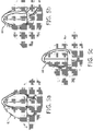
- the three apical view planes extracted from the 3D heart image data by the APn plane segmentation and tracking processor 42 as described above are individually or concurrently displayed on the ultrasound system display 38 as illustrated in FIGURE 5a (of the 4-chamber view), FIGURE 5b (of the 3-chamber view) and FIGURE 5c (of the 2-chamber view).
- the chambers and structures of the heart of each image plane are segmented by an overlay of graphically delineated anatomical borders 62, 64, 66 provided by the heart model.
- the three planes are not treated as unrelated image planes but as three planes of a tri-plane system as illustrated in FIGURE 3 .
- the three APn planes of the heart model are used to extract the three image planes from each successive volume image.
- Those planes are tracked in the new volume by analyzing the gross motion of the anatomical landmarks from the previous tri-plane system to the newly identified tri-plane system. This is done by optical flow or image registration such as by use of mutual information, block matching or feature matching, for instance.
- the motion of the landmarks from one plane to the next is used to find a motion vector for each plane and the three motion vectors of the three planes are used to determine a composite motion vector (transformation) of the tri-plane system.
- the three in-plane motion vectors are used to identify the composite motion of the tri-plane system.
- This transformation is used to model the motion of the tri-plane system as a rigid transformation relative to the probe.
- the rigid transformation identifies the translation and rotation of the tri-plane system from one volume image to the next and this displacement is used to compute the new location of the tri-plane system in the new volume image. Since this is a rigid transformation there is no scaling or warping of the model or image data which eases the computational demands.
- This tracking and tri-plane system updating is repeated for each new volume image acquisition. Occasionally, to guard against excessive heart or probe motion, the processing can be re-initialized as described above.
- FIGURE 4 illustrates a typical sequence of reference plane segmentation and tracking in accordance with the principles of the present invention.
- a 3D volume image of the heart is acquired by apical scanning. Since the heart is scanned apically, the APn plane segmentation and tracking processor 42 can be preconditioned to expect to find the apex of the heart at the top of the volume image.
- the APn plane segmentation and tracking processor 42 segments the AP4, AP3, and AP2 view planes using the heart model to identify the pose of the heart and fits the heart model to the 3D image data as described above.
- the processor uses the desired plane locations of the fitted heart model to extract and display the tri-plane images.
- step 56 a new 3D volume image is acquired and in step 58 the tri-plane system in the new volume image is tracked by rigid transformation.
- step 60 the tracked tri-plane system images are extracted from the new image data and the displayed tri-plane images are updated on the display.
- AP4, AP3 and AP2 views may alternatively or additionally be acquired and displayed.
- the ultrasound system may be used to display AP4, AP5 and AP3 views, for instance, or four different view planes.
- the tracking information may be used to update the planes of a tri-plane display which only scans the three desired view planes and not an entire volume each time. For example, after the heart model has been fitted to the heart anatomy in a volume image, only the tri-planes can be scanned for the next update.
- Three newly scanned image planes can be compared with the previous tri-planes and the computed composite motion data (tracking data) used to scan the tri-planes at the updated plane locations for display.
- the tracking data is thus used to steer the direction of plane scanning of the next tri-plane acquisition by control of the beamform controller as as shown in FIGURE 1 .
- the process can be updated and re-initialized by acquiring and processing a new volume image and the tri-plane scanning commenced again.
- the 3D image data can be transformed to fit the heart model instead of the reverse for segmentation.
Landscapes
- Engineering & Computer Science (AREA)
- Health & Medical Sciences (AREA)
- Life Sciences & Earth Sciences (AREA)
- Physics & Mathematics (AREA)
- Remote Sensing (AREA)
- Radar, Positioning & Navigation (AREA)
- General Physics & Mathematics (AREA)
- Medical Informatics (AREA)
- General Health & Medical Sciences (AREA)
- Surgery (AREA)
- Veterinary Medicine (AREA)
- Radiology & Medical Imaging (AREA)
- Biomedical Technology (AREA)
- Heart & Thoracic Surgery (AREA)
- Nuclear Medicine, Radiotherapy & Molecular Imaging (AREA)
- Molecular Biology (AREA)
- Biophysics (AREA)
- Animal Behavior & Ethology (AREA)
- Pathology (AREA)
- Public Health (AREA)
- Computer Vision & Pattern Recognition (AREA)
- Computer Networks & Wireless Communication (AREA)
- Theoretical Computer Science (AREA)
- Acoustics & Sound (AREA)
- Multimedia (AREA)
- Cardiology (AREA)
- Hematology (AREA)
- Quality & Reliability (AREA)
- Gynecology & Obstetrics (AREA)
- Software Systems (AREA)
- Ultra Sonic Daignosis Equipment (AREA)
- Image Processing (AREA)
Claims (11)
- Système d'imagerie diagnostique ultrasonore (10) pour acquérir une pluralité de plans de visualisation standard d'un cœur comprenant:une sonde à réseau matriciel agencée pour acquérir des données d'image en volume 3D du cœur comprenant des repères anatomiques;une mémoire (40) comprenant des données d'un modèle géométrique de cœur comprenant des points cibles de repère;un processeur de segmentation et de suivi (42), en réponse aux données d'image en volume 3D du cœur et aux données de modèle de cœur, où le processeur de segmentation et de suivi (42) est agencé pour enregistrer automatiquement les données d'image en volume 3D et le modèle de cœur, pour segmenter les données d'image en volume 3D en utilisant des points cibles de repère des plans de visualisation prédéterminés souhaités pour extraire des données d'image en volume 3D la pluralité de plans de visualisation respectifs qui contiennent le plus complètement ces repères; etun afficheur d'images (38) qui répond au processeur de segmentation et de suivi (42) et est agencé pour afficher des images de la pluralité extraite de plans de visualisation,où le processeur de segmentation et de suivi (42) est en outre agencé pour suivre en analysant un mouvement des repères anatomiques des données d'image en volume 3D une acquisition d'images successives de la pluralité des plans de visualisation extraits pour la mise à jour des images affichées, etoù le processeur de segmentation et de suivi (42) est configuré pour suivre la pluralité de plans de visualisation en tant que système multiplans et pour suivre le système multiplans par transformation rigide de manière à calculer un nouvel emplacement du système multiplans, où pour chaque plan de visualisation un vecteur de mouvement des repères est déterminé et utilisé pour déterminer la transformation composite du système multiplans.
- Système d'imagerie diagnostique ultrasonore (10) selon la revendication 1, dans lequel la pluralité de plans de visualisation prédéterminés comprend en outre trois plans image; et
dans lequel le processeur de segmentation et de suivi (42) est configuré pour suivre les trois plans image en tant que système triplans. - Système d'imagerie diagnostique ultrasonore (10) selon la revendication 2, dans lequel les trois plans image comprennent en outre un plan de visualisation AP4, un plan de visualisation AP3, et un plan de visualisation AP2.
- Système d'imagerie diagnostique ultrasonore (10) selon la revendication 2 ou 3, dans lequel le système d'imagerie diagnostique ultrasonore (10) comprend en outre un contrôleur de formation de faisceau (76) configuré pour être commandé en utilisant le mouvement des repères anatomiques pour commander une direction de balayage du plan d'une acquisition successive afin de ne balayer que le triplans pour la mise à jour des images affichées.
- Système d'imagerie diagnostique ultrasonore (10) selon la revendication 1, dans lequel le processeur de segmentation et de suivi (42) est configuré pour suivre la pluralité de plans de visualisation prédéterminés à travers une pluralité d'images du cœur 3D acquises successivement.
- Système d'imagerie diagnostique ultrasonore (10) selon la revendication 1, dans lequel le processeur de segmentation et de suivi (42) est configuré pour suivre la pluralité de plans de visualisation prédéterminés en commandant la direction de balayage des plans image acquises successivement.
- Système d'imagerie diagnostique ultrasonore (10) selon la revendication 1, dans lequel le processeur de segmentation et de suivi (42) peut en outre fonctionner pour mettre à jour périodiquement l'enregistrement des données d'image du cœur et des données de modèle du cœur.
- Procédé pour acquérir une pluralité de plans de visualisation standard d'un cœur par imagerie ultrasonore, comprenant:l'acquisition (50) de données d'image en volume 3D du cœur, y compris des repères anatomiques avec une sonde à réseau matriciel;l'enregistrement des données d'image en volume 3D du cœur avec des données d'un modèle géométrique de cœur stockées dans une mémoire (40), où le modèle géométrique de cœur comprend des points cibles de repère;la segmentation (52) des données d'image en volume 3D en utilisant des points cibles de repère des plans de visualisation prédéterminés souhaités pour extraire des données d'image en volume d'image 3D la pluralité de plans de visualisation respectifs qui contiennent le plus complètement ces repères;l'affichage (54) des images de la pluralité de plans de visualisation sur un afficheur d'images; etle suivi (58), en analysant un mouvement des repères anatomiques des données d'image en volume 3D, d'une acquisition d'images successives de la pluralité des plans de visualisation extraits pour la mise à jour (60) des images affichées, où le suivi comprend en outre le suivi de la pluralité de plans de visualisation en tant que système multiplans, et où le système multiplans est suivi par une transformation rigide de manière à calculer un nouvel emplacement du système multiplans, où pour chaque plan un vecteur de mouvement des repères est déterminé et utilisé pour déterminer la transformation composite du système multiplans.
- Procédé selon la revendication 8, comprenant en outre:l'acquisition d'une pluralité de données d'image en volume 3D successives; etle suivi de la pluralité de plans de visualisation dans la pluralité de données d'image en volume 3D acquises successivement.
- Procédé selon la revendication 8, dans lequel le suivi comprend en outre la commande de la direction des plans de balayage dans des intervalles d'acquisitions successives.
- Procédé selon la revendication 10, comprenant en outre la mise à jour périodique de l'enregistrement des données d'image du cœur avec les données du modèle géométrique de cœur.
Applications Claiming Priority (2)
| Application Number | Priority Date | Filing Date | Title |
|---|---|---|---|
| US201361899895P | 2013-11-05 | 2013-11-05 | |
| PCT/IB2014/065779 WO2015068099A1 (fr) | 2013-11-05 | 2014-11-04 | Segmentation automatisée d'images triplans pour imagerie ultrasonore en temps réel |
Publications (2)
| Publication Number | Publication Date |
|---|---|
| EP3066643A1 EP3066643A1 (fr) | 2016-09-14 |
| EP3066643B1 true EP3066643B1 (fr) | 2020-05-27 |
Family
ID=51900925
Family Applications (1)
| Application Number | Title | Priority Date | Filing Date |
|---|---|---|---|
| EP14799216.8A Active EP3066643B1 (fr) | 2013-11-05 | 2014-11-04 | Segmentation automatisée d'images triplans pour imagerie ultrasonore en temps réel |
Country Status (7)
| Country | Link |
|---|---|
| US (2) | US10123781B2 (fr) |
| EP (1) | EP3066643B1 (fr) |
| JP (2) | JP6441335B2 (fr) |
| CN (1) | CN105900140B (fr) |
| BR (1) | BR112016009829B1 (fr) |
| RU (1) | RU2677055C2 (fr) |
| WO (1) | WO2015068099A1 (fr) |
Families Citing this family (28)
| Publication number | Priority date | Publication date | Assignee | Title |
|---|---|---|---|---|
| WO2015068099A1 (fr) * | 2013-11-05 | 2015-05-14 | Koninklijke Philips N.V. | Segmentation automatisée d'images triplans pour imagerie ultrasonore en temps réel |
| KR102255831B1 (ko) * | 2014-03-26 | 2021-05-25 | 삼성전자주식회사 | 초음파 장치 및 초음파 장치의 영상 인식 방법 |
| KR101619802B1 (ko) * | 2014-06-18 | 2016-05-11 | 기초과학연구원 | 심장 좌심실의 3차원 영상 생성 방법 및 그 장치 |
| EP2989988B1 (fr) * | 2014-08-29 | 2017-10-04 | Samsung Medison Co., Ltd. | Appareil d'affichage d'image ultrasonore et procede d'affichage d'une image ultrasonore |
| US11006927B2 (en) * | 2015-03-31 | 2021-05-18 | Koninklijke Philips N.V. | Ultrasound imaging apparatus |
| US11413006B2 (en) * | 2016-04-26 | 2022-08-16 | Koninklijke Philips N.V. | 3D image compounding for ultrasound fetal imaging |
| US10362950B2 (en) | 2016-06-24 | 2019-07-30 | Analytics For Life Inc. | Non-invasive method and system for measuring myocardial ischemia, stenosis identification, localization and fractional flow reserve estimation |
| US10292596B2 (en) | 2016-09-21 | 2019-05-21 | Analytics For Life Inc. | Method and system for visualization of heart tissue at risk |
| DE102016117889B3 (de) * | 2016-09-22 | 2018-03-15 | Tomtec Imaging Systems Gmbh | Verfahren und Vorrichtung zur Korrektur von durch Tracking-Verfahren ermittelten dynamischen Modellen |
| JP7157074B2 (ja) * | 2016-12-20 | 2022-10-19 | コーニンクレッカ フィリップス エヌ ヴェ | 医療機器、特に心臓カテーテルのためのナビゲーション・プラットフォーム |
| CN110520933B (zh) * | 2017-03-01 | 2023-10-27 | 皇家飞利浦有限公司 | 超声心动图上下文测量工具 |
| EP3381512A1 (fr) | 2017-03-30 | 2018-10-03 | Koninklijke Philips N.V. | Détermination d'au moins une image bidimensionnelle finale pour visualiser un objet d'intérêt dans un volume ultrasonore tridimensionnel |
| US11534133B2 (en) | 2017-04-27 | 2022-12-27 | Shenzhen Mindray Bio-Medical Electronics Co., Ltd. | Ultrasonic detection method and ultrasonic imaging system for fetal heart |
| US10299764B2 (en) * | 2017-05-10 | 2019-05-28 | General Electric Company | Method and system for enhanced visualization of moving structures with cross-plane ultrasound images |
| EP3668408A1 (fr) * | 2017-08-17 | 2020-06-24 | Koninklijke Philips N.V. | Système à ultrasons capable d'extraction de plans d'image à partir de données de volume par interaction par effleurement avec une image |
| WO2019155037A1 (fr) * | 2018-02-09 | 2019-08-15 | Koninklijke Philips N.V. | Quantification de rigidité de tissu multi-paramétrique |
| CN113610923B (zh) * | 2018-07-26 | 2025-07-22 | 上海联影智能医疗科技有限公司 | 扫描定位方法、装置、计算机设备及计算机可读存储介质 |
| EP3711673A1 (fr) | 2019-03-18 | 2020-09-23 | Koninklijke Philips N.V. | Procédés et systèmes permettant de régler le champ de vision d'une sonde à ultrasons |
| EP4013309B1 (fr) * | 2019-08-15 | 2022-10-26 | Koninklijke Philips N.V. | Système d'imagerie ultrasonore multi-plan orientable |
| EP3896652A1 (fr) * | 2020-04-16 | 2021-10-20 | Koninklijke Philips N.V. | Détection de défaillances de segmentation d'une image |
| EP4241246A1 (fr) * | 2020-11-05 | 2023-09-13 | Koninklijke Philips N.V. | Rendu et affichage d'une représentation 3d d'une structure anatomique |
| US12307556B2 (en) * | 2021-03-22 | 2025-05-20 | GE Precision Healthcare LLC | Automatic model-based navigation system and method for ultrasound images |
| US11922647B2 (en) * | 2021-09-08 | 2024-03-05 | Canon Medical Systems Corporation | Image rendering method and apparatus |
| KR102917172B1 (ko) * | 2022-04-19 | 2026-01-23 | 주식회사 온택트헬스 | 심장 초음파에 대한 가이드 방법 및 이를 이용한 심장 초음파에 대한 가이드용 디바이스 |
| KR102819588B1 (ko) * | 2022-08-01 | 2025-06-13 | 주식회사 온택트헬스 | 도플러 초음파 영상에 대한 정보 제공 방법 및 이를 이용한 도플러 초음파 영상에 대한 정보 제공용 디바이스 |
| EP4389016A1 (fr) * | 2022-12-21 | 2024-06-26 | Koninklijke Philips N.V. | Procédé d'acquisition d'image |
| KR102947965B1 (ko) | 2023-08-04 | 2026-04-03 | 주식회사 온택트헬스 | 도플러 초음파 영상 분류에 대한 정보 제공 방법 및 이를 이용한 도플러 초음파 영상 분류에 대한 정보 제공용 디바이스 |
| US20260053466A1 (en) * | 2024-08-20 | 2026-02-26 | GE Precision Healthcare LLC | System for determining information related to cardiac deformation of an anatomical feature of a heart using deformation imaging |
Family Cites Families (18)
| Publication number | Priority date | Publication date | Assignee | Title |
|---|---|---|---|---|
| US6106466A (en) * | 1997-04-24 | 2000-08-22 | University Of Washington | Automated delineation of heart contours from images using reconstruction-based modeling |
| US5997479A (en) | 1998-05-28 | 1999-12-07 | Hewlett-Packard Company | Phased array acoustic systems with intra-group processors |
| RU2173480C2 (ru) * | 1999-11-03 | 2001-09-10 | Терпиловский Алексей Анатольевич | Способ создания виртуальной модели биологического объекта |
| US6468216B1 (en) | 2000-08-24 | 2002-10-22 | Kininklijke Philips Electronics N.V. | Ultrasonic diagnostic imaging of the coronary arteries |
| JP3802508B2 (ja) * | 2003-04-21 | 2006-07-26 | アロカ株式会社 | 超音波診断装置 |
| US7555151B2 (en) * | 2004-09-02 | 2009-06-30 | Siemens Medical Solutions Usa, Inc. | System and method for tracking anatomical structures in three dimensional images |
| US7327872B2 (en) * | 2004-10-13 | 2008-02-05 | General Electric Company | Method and system for registering 3D models of anatomical regions with projection images of the same |
| JP5122743B2 (ja) | 2004-12-20 | 2013-01-16 | ゼネラル・エレクトリック・カンパニイ | インターベンショナルシステム内で3d画像を位置合わせするシステム |
| JP5481069B2 (ja) * | 2005-12-20 | 2014-04-23 | コーニンクレッカ フィリップス エヌ ヴェ | 対象物の少なくとも一部を細かく再現したものを再構成する再構成ユニット |
| EP2054829A2 (fr) * | 2006-08-11 | 2009-05-06 | Koninklijke Philips Electronics N.V. | Applications liées au contexte d'image associé à l'anatomie pour un diagnostic efficace |
| US7889912B2 (en) * | 2006-09-15 | 2011-02-15 | The General Electric Company | Method for real-time tracking of cardiac structures in 3D echocardiography |
| US20110201935A1 (en) * | 2008-10-22 | 2011-08-18 | Koninklijke Philips Electronics N.V. | 3-d ultrasound imaging |
| US8265363B2 (en) * | 2009-02-04 | 2012-09-11 | General Electric Company | Method and apparatus for automatically identifying image views in a 3D dataset |
| US20100249589A1 (en) * | 2009-03-25 | 2010-09-30 | Peter Lysyansky | System and method for functional ultrasound imaging |
| GB201117804D0 (en) * | 2011-10-14 | 2011-11-30 | Siemens Medical Solutions | Automatic local contrast quantification tool |
| US9277970B2 (en) * | 2012-07-19 | 2016-03-08 | Siemens Aktiengesellschaft | System and method for patient specific planning and guidance of ablative procedures for cardiac arrhythmias |
| CN104797199B (zh) * | 2012-11-20 | 2018-02-23 | 皇家飞利浦有限公司 | 用于实时胎儿心脏评估的标准平面的自动定位 |
| WO2015068099A1 (fr) * | 2013-11-05 | 2015-05-14 | Koninklijke Philips N.V. | Segmentation automatisée d'images triplans pour imagerie ultrasonore en temps réel |
-
2014
- 2014-11-04 WO PCT/IB2014/065779 patent/WO2015068099A1/fr not_active Ceased
- 2014-11-04 RU RU2016122066A patent/RU2677055C2/ru active
- 2014-11-04 CN CN201480060603.9A patent/CN105900140B/zh active Active
- 2014-11-04 BR BR112016009829-3A patent/BR112016009829B1/pt not_active IP Right Cessation
- 2014-11-04 US US15/032,719 patent/US10123781B2/en active Active
- 2014-11-04 JP JP2016526918A patent/JP6441335B2/ja active Active
- 2014-11-04 EP EP14799216.8A patent/EP3066643B1/fr active Active
-
2018
- 2018-10-24 US US16/169,751 patent/US10799218B2/en active Active
- 2018-11-21 JP JP2018218117A patent/JP6745861B2/ja not_active Expired - Fee Related
Non-Patent Citations (1)
| Title |
|---|
| None * |
Also Published As
| Publication number | Publication date |
|---|---|
| JP2019022824A (ja) | 2019-02-14 |
| US10799218B2 (en) | 2020-10-13 |
| US10123781B2 (en) | 2018-11-13 |
| CN105900140A (zh) | 2016-08-24 |
| US20160249885A1 (en) | 2016-09-01 |
| RU2016122066A (ru) | 2017-12-11 |
| JP2016534803A (ja) | 2016-11-10 |
| BR112016009829B1 (pt) | 2022-02-22 |
| EP3066643A1 (fr) | 2016-09-14 |
| RU2016122066A3 (fr) | 2018-06-26 |
| BR112016009829A2 (fr) | 2017-08-01 |
| RU2677055C2 (ru) | 2019-01-15 |
| JP6745861B2 (ja) | 2020-08-26 |
| WO2015068099A1 (fr) | 2015-05-14 |
| CN105900140B (zh) | 2019-02-05 |
| JP6441335B2 (ja) | 2018-12-19 |
| US20190059858A1 (en) | 2019-02-28 |
Similar Documents
| Publication | Publication Date | Title |
|---|---|---|
| US10799218B2 (en) | Automated segmentation of tri-plane images for real time ultrasonic imaging | |
| EP4061231B1 (fr) | Aide à la mesure intelligente pour imagerie par ultrasons et dispositifs, systèmes et procédés associés | |
| US9179890B2 (en) | Model-based positioning for intracardiac echocardiography volume stitching | |
| US8073215B2 (en) | Automated detection of planes from three-dimensional echocardiographic data | |
| JP6537981B2 (ja) | 複数の三次元ビューからの大きな対象のセグメンテーション | |
| RU2653274C2 (ru) | Связанная сегментация в стандартных и контрастных ультразвуковых 3d-изображениях | |
| Leung et al. | Automated border detection in three-dimensional echocardiography: principles and promises | |
| US8948484B2 (en) | Method and system for automatic view planning for cardiac magnetic resonance imaging acquisition | |
| US10398411B2 (en) | Automatic alignment of ultrasound volumes | |
| US12541893B2 (en) | Bi-plane and three-dimensional ultrasound image acquisition for generating roadmap images, and associated systems and devices | |
| EP2392942B1 (fr) | Quantification du débit cardiaque au moyen de données d'images volumétriques | |
| US20100195881A1 (en) | Method and apparatus for automatically identifying image views in a 3d dataset | |
| CN112955934A (zh) | 识别医学图像中的介入设备 | |
| WO2021099171A1 (fr) | Systèmes et procédés de criblage par imagerie | |
| US20250176946A1 (en) | System and method for real-time fusion of acoustic image with reference image | |
| WO2020216752A1 (fr) | Système et procédé de combinaison d'images acoustiques bidimensionnelles par apprentissage profond | |
| US20240404066A1 (en) | System and method for segmenting an anatomical structure | |
| Myronenko et al. | LV motion tracking from 3D echocardiography using textural and structural information | |
| EP4078511B1 (fr) | Générer une carte de confiance d'une segmentation à partir des variations des noeuds d'un modèle dans une pluralité de segmentations d'images anatomiques basées sur le modèle et perturbées différemment | |
| Voigt et al. | Robust live tracking of mitral valve annulus for minimally-invasive intervention guidance | |
| Van Stralen et al. | A semi-automatic endocardial border detection method for 4D ultrasound data |
Legal Events
| Date | Code | Title | Description |
|---|---|---|---|
| PUAI | Public reference made under article 153(3) epc to a published international application that has entered the european phase |
Free format text: ORIGINAL CODE: 0009012 |
|
| 17P | Request for examination filed |
Effective date: 20160606 |
|
| AK | Designated contracting states |
Kind code of ref document: A1 Designated state(s): AL AT BE BG CH CY CZ DE DK EE ES FI FR GB GR HR HU IE IS IT LI LT LU LV MC MK MT NL NO PL PT RO RS SE SI SK SM TR |
|
| AX | Request for extension of the european patent |
Extension state: BA ME |
|
| DAX | Request for extension of the european patent (deleted) | ||
| STAA | Information on the status of an ep patent application or granted ep patent |
Free format text: STATUS: EXAMINATION IS IN PROGRESS |
|
| 17Q | First examination report despatched |
Effective date: 20190506 |
|
| REG | Reference to a national code |
Ref country code: DE Ref legal event code: R079 Ref document number: 602014065966 Country of ref document: DE Free format text: PREVIOUS MAIN CLASS: G06T0007000000 Ipc: G06T0007246000 |
|
| GRAP | Despatch of communication of intention to grant a patent |
Free format text: ORIGINAL CODE: EPIDOSNIGR1 |
|
| STAA | Information on the status of an ep patent application or granted ep patent |
Free format text: STATUS: GRANT OF PATENT IS INTENDED |
|
| RIC1 | Information provided on ipc code assigned before grant |
Ipc: G06T 7/11 20170101ALI20191120BHEP Ipc: G06T 7/246 20170101AFI20191120BHEP |
|
| INTG | Intention to grant announced |
Effective date: 20191213 |
|
| RAP1 | Party data changed (applicant data changed or rights of an application transferred) |
Owner name: KONINKLIJKE PHILIPS N.V. |
|
| GRAS | Grant fee paid |
Free format text: ORIGINAL CODE: EPIDOSNIGR3 |
|
| GRAA | (expected) grant |
Free format text: ORIGINAL CODE: 0009210 |
|
| STAA | Information on the status of an ep patent application or granted ep patent |
Free format text: STATUS: THE PATENT HAS BEEN GRANTED |
|
| AK | Designated contracting states |
Kind code of ref document: B1 Designated state(s): AL AT BE BG CH CY CZ DE DK EE ES FI FR GB GR HR HU IE IS IT LI LT LU LV MC MK MT NL NO PL PT RO RS SE SI SK SM TR |
|
| REG | Reference to a national code |
Ref country code: GB Ref legal event code: FG4D |
|
| REG | Reference to a national code |
Ref country code: CH Ref legal event code: EP |
|
| REG | Reference to a national code |
Ref country code: DE Ref legal event code: R096 Ref document number: 602014065966 Country of ref document: DE |
|
| REG | Reference to a national code |
Ref country code: AT Ref legal event code: REF Ref document number: 1275326 Country of ref document: AT Kind code of ref document: T Effective date: 20200615 |
|
| REG | Reference to a national code |
Ref country code: DE Ref legal event code: R084 Ref document number: 602014065966 Country of ref document: DE |
|
| REG | Reference to a national code |
Ref country code: LT Ref legal event code: MG4D |
|
| PG25 | Lapsed in a contracting state [announced via postgrant information from national office to epo] |
Ref country code: LT Free format text: LAPSE BECAUSE OF FAILURE TO SUBMIT A TRANSLATION OF THE DESCRIPTION OR TO PAY THE FEE WITHIN THE PRESCRIBED TIME-LIMIT Effective date: 20200527 Ref country code: FI Free format text: LAPSE BECAUSE OF FAILURE TO SUBMIT A TRANSLATION OF THE DESCRIPTION OR TO PAY THE FEE WITHIN THE PRESCRIBED TIME-LIMIT Effective date: 20200527 Ref country code: NO Free format text: LAPSE BECAUSE OF FAILURE TO SUBMIT A TRANSLATION OF THE DESCRIPTION OR TO PAY THE FEE WITHIN THE PRESCRIBED TIME-LIMIT Effective date: 20200827 Ref country code: GR Free format text: LAPSE BECAUSE OF FAILURE TO SUBMIT A TRANSLATION OF THE DESCRIPTION OR TO PAY THE FEE WITHIN THE PRESCRIBED TIME-LIMIT Effective date: 20200828 Ref country code: PT Free format text: LAPSE BECAUSE OF FAILURE TO SUBMIT A TRANSLATION OF THE DESCRIPTION OR TO PAY THE FEE WITHIN THE PRESCRIBED TIME-LIMIT Effective date: 20200928 Ref country code: IS Free format text: LAPSE BECAUSE OF FAILURE TO SUBMIT A TRANSLATION OF THE DESCRIPTION OR TO PAY THE FEE WITHIN THE PRESCRIBED TIME-LIMIT Effective date: 20200927 Ref country code: SE Free format text: LAPSE BECAUSE OF FAILURE TO SUBMIT A TRANSLATION OF THE DESCRIPTION OR TO PAY THE FEE WITHIN THE PRESCRIBED TIME-LIMIT Effective date: 20200527 |
|
| REG | Reference to a national code |
Ref country code: NL Ref legal event code: MP Effective date: 20200527 |
|
| PG25 | Lapsed in a contracting state [announced via postgrant information from national office to epo] |
Ref country code: RS Free format text: LAPSE BECAUSE OF FAILURE TO SUBMIT A TRANSLATION OF THE DESCRIPTION OR TO PAY THE FEE WITHIN THE PRESCRIBED TIME-LIMIT Effective date: 20200527 Ref country code: HR Free format text: LAPSE BECAUSE OF FAILURE TO SUBMIT A TRANSLATION OF THE DESCRIPTION OR TO PAY THE FEE WITHIN THE PRESCRIBED TIME-LIMIT Effective date: 20200527 Ref country code: LV Free format text: LAPSE BECAUSE OF FAILURE TO SUBMIT A TRANSLATION OF THE DESCRIPTION OR TO PAY THE FEE WITHIN THE PRESCRIBED TIME-LIMIT Effective date: 20200527 Ref country code: BG Free format text: LAPSE BECAUSE OF FAILURE TO SUBMIT A TRANSLATION OF THE DESCRIPTION OR TO PAY THE FEE WITHIN THE PRESCRIBED TIME-LIMIT Effective date: 20200827 |
|
| REG | Reference to a national code |
Ref country code: AT Ref legal event code: MK05 Ref document number: 1275326 Country of ref document: AT Kind code of ref document: T Effective date: 20200527 |
|
| REG | Reference to a national code |
Ref country code: GB Ref legal event code: 746 Effective date: 20201130 |
|
| PG25 | Lapsed in a contracting state [announced via postgrant information from national office to epo] |
Ref country code: AL Free format text: LAPSE BECAUSE OF FAILURE TO SUBMIT A TRANSLATION OF THE DESCRIPTION OR TO PAY THE FEE WITHIN THE PRESCRIBED TIME-LIMIT Effective date: 20200527 Ref country code: NL Free format text: LAPSE BECAUSE OF FAILURE TO SUBMIT A TRANSLATION OF THE DESCRIPTION OR TO PAY THE FEE WITHIN THE PRESCRIBED TIME-LIMIT Effective date: 20200527 |
|
| PG25 | Lapsed in a contracting state [announced via postgrant information from national office to epo] |
Ref country code: EE Free format text: LAPSE BECAUSE OF FAILURE TO SUBMIT A TRANSLATION OF THE DESCRIPTION OR TO PAY THE FEE WITHIN THE PRESCRIBED TIME-LIMIT Effective date: 20200527 Ref country code: SM Free format text: LAPSE BECAUSE OF FAILURE TO SUBMIT A TRANSLATION OF THE DESCRIPTION OR TO PAY THE FEE WITHIN THE PRESCRIBED TIME-LIMIT Effective date: 20200527 Ref country code: CZ Free format text: LAPSE BECAUSE OF FAILURE TO SUBMIT A TRANSLATION OF THE DESCRIPTION OR TO PAY THE FEE WITHIN THE PRESCRIBED TIME-LIMIT Effective date: 20200527 Ref country code: RO Free format text: LAPSE BECAUSE OF FAILURE TO SUBMIT A TRANSLATION OF THE DESCRIPTION OR TO PAY THE FEE WITHIN THE PRESCRIBED TIME-LIMIT Effective date: 20200527 Ref country code: ES Free format text: LAPSE BECAUSE OF FAILURE TO SUBMIT A TRANSLATION OF THE DESCRIPTION OR TO PAY THE FEE WITHIN THE PRESCRIBED TIME-LIMIT Effective date: 20200527 Ref country code: AT Free format text: LAPSE BECAUSE OF FAILURE TO SUBMIT A TRANSLATION OF THE DESCRIPTION OR TO PAY THE FEE WITHIN THE PRESCRIBED TIME-LIMIT Effective date: 20200527 Ref country code: DK Free format text: LAPSE BECAUSE OF FAILURE TO SUBMIT A TRANSLATION OF THE DESCRIPTION OR TO PAY THE FEE WITHIN THE PRESCRIBED TIME-LIMIT Effective date: 20200527 Ref country code: IT Free format text: LAPSE BECAUSE OF FAILURE TO SUBMIT A TRANSLATION OF THE DESCRIPTION OR TO PAY THE FEE WITHIN THE PRESCRIBED TIME-LIMIT Effective date: 20200527 |
|
| PG25 | Lapsed in a contracting state [announced via postgrant information from national office to epo] |
Ref country code: PL Free format text: LAPSE BECAUSE OF FAILURE TO SUBMIT A TRANSLATION OF THE DESCRIPTION OR TO PAY THE FEE WITHIN THE PRESCRIBED TIME-LIMIT Effective date: 20200527 Ref country code: SK Free format text: LAPSE BECAUSE OF FAILURE TO SUBMIT A TRANSLATION OF THE DESCRIPTION OR TO PAY THE FEE WITHIN THE PRESCRIBED TIME-LIMIT Effective date: 20200527 |
|
| REG | Reference to a national code |
Ref country code: DE Ref legal event code: R097 Ref document number: 602014065966 Country of ref document: DE |
|
| PLBE | No opposition filed within time limit |
Free format text: ORIGINAL CODE: 0009261 |
|
| STAA | Information on the status of an ep patent application or granted ep patent |
Free format text: STATUS: NO OPPOSITION FILED WITHIN TIME LIMIT |
|
| 26N | No opposition filed |
Effective date: 20210302 |
|
| PG25 | Lapsed in a contracting state [announced via postgrant information from national office to epo] |
Ref country code: SI Free format text: LAPSE BECAUSE OF FAILURE TO SUBMIT A TRANSLATION OF THE DESCRIPTION OR TO PAY THE FEE WITHIN THE PRESCRIBED TIME-LIMIT Effective date: 20200527 |
|
| PG25 | Lapsed in a contracting state [announced via postgrant information from national office to epo] |
Ref country code: MC Free format text: LAPSE BECAUSE OF FAILURE TO SUBMIT A TRANSLATION OF THE DESCRIPTION OR TO PAY THE FEE WITHIN THE PRESCRIBED TIME-LIMIT Effective date: 20200527 |
|
| REG | Reference to a national code |
Ref country code: CH Ref legal event code: PL |
|
| PG25 | Lapsed in a contracting state [announced via postgrant information from national office to epo] |
Ref country code: LU Free format text: LAPSE BECAUSE OF NON-PAYMENT OF DUE FEES Effective date: 20201104 |
|
| REG | Reference to a national code |
Ref country code: BE Ref legal event code: MM Effective date: 20201130 |
|
| PG25 | Lapsed in a contracting state [announced via postgrant information from national office to epo] |
Ref country code: CH Free format text: LAPSE BECAUSE OF NON-PAYMENT OF DUE FEES Effective date: 20201130 Ref country code: LI Free format text: LAPSE BECAUSE OF NON-PAYMENT OF DUE FEES Effective date: 20201130 |
|
| PG25 | Lapsed in a contracting state [announced via postgrant information from national office to epo] |
Ref country code: IE Free format text: LAPSE BECAUSE OF NON-PAYMENT OF DUE FEES Effective date: 20201104 |
|
| PG25 | Lapsed in a contracting state [announced via postgrant information from national office to epo] |
Ref country code: TR Free format text: LAPSE BECAUSE OF FAILURE TO SUBMIT A TRANSLATION OF THE DESCRIPTION OR TO PAY THE FEE WITHIN THE PRESCRIBED TIME-LIMIT Effective date: 20200527 Ref country code: MT Free format text: LAPSE BECAUSE OF FAILURE TO SUBMIT A TRANSLATION OF THE DESCRIPTION OR TO PAY THE FEE WITHIN THE PRESCRIBED TIME-LIMIT Effective date: 20200527 Ref country code: CY Free format text: LAPSE BECAUSE OF FAILURE TO SUBMIT A TRANSLATION OF THE DESCRIPTION OR TO PAY THE FEE WITHIN THE PRESCRIBED TIME-LIMIT Effective date: 20200527 |
|
| PG25 | Lapsed in a contracting state [announced via postgrant information from national office to epo] |
Ref country code: MK Free format text: LAPSE BECAUSE OF FAILURE TO SUBMIT A TRANSLATION OF THE DESCRIPTION OR TO PAY THE FEE WITHIN THE PRESCRIBED TIME-LIMIT Effective date: 20200527 |
|
| PG25 | Lapsed in a contracting state [announced via postgrant information from national office to epo] |
Ref country code: BE Free format text: LAPSE BECAUSE OF NON-PAYMENT OF DUE FEES Effective date: 20201130 |
|
| PGFP | Annual fee paid to national office [announced via postgrant information from national office to epo] |
Ref country code: GB Payment date: 20231121 Year of fee payment: 10 |
|
| PGFP | Annual fee paid to national office [announced via postgrant information from national office to epo] |
Ref country code: FR Payment date: 20231123 Year of fee payment: 10 |
|
| GBPC | Gb: european patent ceased through non-payment of renewal fee |
Effective date: 20241104 |
|
| PG25 | Lapsed in a contracting state [announced via postgrant information from national office to epo] |
Ref country code: GB Free format text: LAPSE BECAUSE OF NON-PAYMENT OF DUE FEES Effective date: 20241104 |
|
| PG25 | Lapsed in a contracting state [announced via postgrant information from national office to epo] |
Ref country code: FR Free format text: LAPSE BECAUSE OF NON-PAYMENT OF DUE FEES Effective date: 20241130 |
|
| PGFP | Annual fee paid to national office [announced via postgrant information from national office to epo] |
Ref country code: DE Payment date: 20251126 Year of fee payment: 12 |