EP3066832B1 - Adaptive prädiktion von koeffizienten von videoblöcken - Google Patents
Adaptive prädiktion von koeffizienten von videoblöcken Download PDFInfo
- Publication number
- EP3066832B1 EP3066832B1 EP14795808.6A EP14795808A EP3066832B1 EP 3066832 B1 EP3066832 B1 EP 3066832B1 EP 14795808 A EP14795808 A EP 14795808A EP 3066832 B1 EP3066832 B1 EP 3066832B1
- Authority
- EP
- European Patent Office
- Prior art keywords
- prediction
- block
- prediction block
- coefficients
- domain
- Prior art date
- Legal status (The legal status is an assumption and is not a legal conclusion. Google has not performed a legal analysis and makes no representation as to the accuracy of the status listed.)
- Active
Links
Images



Classifications
-
- H—ELECTRICITY
- H04—ELECTRIC COMMUNICATION TECHNIQUE
- H04N—PICTORIAL COMMUNICATION, e.g. TELEVISION
- H04N19/00—Methods or arrangements for coding, decoding, compressing or decompressing digital video signals
- H04N19/10—Methods or arrangements for coding, decoding, compressing or decompressing digital video signals using adaptive coding
- H04N19/102—Methods or arrangements for coding, decoding, compressing or decompressing digital video signals using adaptive coding characterised by the element, parameter or selection affected or controlled by the adaptive coding
- H04N19/132—Sampling, masking or truncation of coding units, e.g. adaptive resampling, frame skipping, frame interpolation or high-frequency transform coefficient masking
-
- H—ELECTRICITY
- H04—ELECTRIC COMMUNICATION TECHNIQUE
- H04N—PICTORIAL COMMUNICATION, e.g. TELEVISION
- H04N19/00—Methods or arrangements for coding, decoding, compressing or decompressing digital video signals
- H04N19/10—Methods or arrangements for coding, decoding, compressing or decompressing digital video signals using adaptive coding
- H04N19/102—Methods or arrangements for coding, decoding, compressing or decompressing digital video signals using adaptive coding characterised by the element, parameter or selection affected or controlled by the adaptive coding
- H04N19/103—Selection of coding mode or of prediction mode
-
- H—ELECTRICITY
- H04—ELECTRIC COMMUNICATION TECHNIQUE
- H04N—PICTORIAL COMMUNICATION, e.g. TELEVISION
- H04N19/00—Methods or arrangements for coding, decoding, compressing or decompressing digital video signals
- H04N19/10—Methods or arrangements for coding, decoding, compressing or decompressing digital video signals using adaptive coding
- H04N19/102—Methods or arrangements for coding, decoding, compressing or decompressing digital video signals using adaptive coding characterised by the element, parameter or selection affected or controlled by the adaptive coding
- H04N19/124—Quantisation
-
- H—ELECTRICITY
- H04—ELECTRIC COMMUNICATION TECHNIQUE
- H04N—PICTORIAL COMMUNICATION, e.g. TELEVISION
- H04N19/00—Methods or arrangements for coding, decoding, compressing or decompressing digital video signals
- H04N19/10—Methods or arrangements for coding, decoding, compressing or decompressing digital video signals using adaptive coding
- H04N19/134—Methods or arrangements for coding, decoding, compressing or decompressing digital video signals using adaptive coding characterised by the element, parameter or criterion affecting or controlling the adaptive coding
- H04N19/157—Assigned coding mode, i.e. the coding mode being predefined or preselected to be further used for selection of another element or parameter
-
- H—ELECTRICITY
- H04—ELECTRIC COMMUNICATION TECHNIQUE
- H04N—PICTORIAL COMMUNICATION, e.g. TELEVISION
- H04N19/00—Methods or arrangements for coding, decoding, compressing or decompressing digital video signals
- H04N19/10—Methods or arrangements for coding, decoding, compressing or decompressing digital video signals using adaptive coding
- H04N19/169—Methods or arrangements for coding, decoding, compressing or decompressing digital video signals using adaptive coding characterised by the coding unit, i.e. the structural portion or semantic portion of the video signal being the object or the subject of the adaptive coding
- H04N19/17—Methods or arrangements for coding, decoding, compressing or decompressing digital video signals using adaptive coding characterised by the coding unit, i.e. the structural portion or semantic portion of the video signal being the object or the subject of the adaptive coding the unit being an image region, e.g. an object
- H04N19/176—Methods or arrangements for coding, decoding, compressing or decompressing digital video signals using adaptive coding characterised by the coding unit, i.e. the structural portion or semantic portion of the video signal being the object or the subject of the adaptive coding the unit being an image region, e.g. an object the region being a block, e.g. a macroblock
-
- H—ELECTRICITY
- H04—ELECTRIC COMMUNICATION TECHNIQUE
- H04N—PICTORIAL COMMUNICATION, e.g. TELEVISION
- H04N19/00—Methods or arrangements for coding, decoding, compressing or decompressing digital video signals
- H04N19/10—Methods or arrangements for coding, decoding, compressing or decompressing digital video signals using adaptive coding
- H04N19/169—Methods or arrangements for coding, decoding, compressing or decompressing digital video signals using adaptive coding characterised by the coding unit, i.e. the structural portion or semantic portion of the video signal being the object or the subject of the adaptive coding
- H04N19/18—Methods or arrangements for coding, decoding, compressing or decompressing digital video signals using adaptive coding characterised by the coding unit, i.e. the structural portion or semantic portion of the video signal being the object or the subject of the adaptive coding the unit being a set of transform coefficients
-
- H—ELECTRICITY
- H04—ELECTRIC COMMUNICATION TECHNIQUE
- H04N—PICTORIAL COMMUNICATION, e.g. TELEVISION
- H04N19/00—Methods or arrangements for coding, decoding, compressing or decompressing digital video signals
- H04N19/10—Methods or arrangements for coding, decoding, compressing or decompressing digital video signals using adaptive coding
- H04N19/169—Methods or arrangements for coding, decoding, compressing or decompressing digital video signals using adaptive coding characterised by the coding unit, i.e. the structural portion or semantic portion of the video signal being the object or the subject of the adaptive coding
- H04N19/182—Methods or arrangements for coding, decoding, compressing or decompressing digital video signals using adaptive coding characterised by the coding unit, i.e. the structural portion or semantic portion of the video signal being the object or the subject of the adaptive coding the unit being a pixel
-
- H—ELECTRICITY
- H04—ELECTRIC COMMUNICATION TECHNIQUE
- H04N—PICTORIAL COMMUNICATION, e.g. TELEVISION
- H04N19/00—Methods or arrangements for coding, decoding, compressing or decompressing digital video signals
- H04N19/50—Methods or arrangements for coding, decoding, compressing or decompressing digital video signals using predictive coding
Definitions
- the invention relates to an improved compression algorithm for video compression codecs, and in particular to a method, apparatus and computer program for implementing the method.
- the decoded video at the receiving end is required to be as faithful to the original video prior to the encoding as possible.
- Typical examples of such kind of applications can be found in medical imaging applications, in the transmission of signals from cameras throughout the production chain, in-screen mirroring systems (when the content on the screen of a device is mirrored in real-time to a different screen), and so on.
- the quality of decoded videos is becoming an extremely important issue even in the context of consumer applications. Users want new broadcasting systems to deliver videos as accurately as possible, with the lowest visible errors. Under these quality constraints, the efficiency of HEVC with respect to its predecessor AVC has been found to decrease considerably.
- conventional prediction methods used in the above coding standards to provide compression, are based on the minimization of distortion metrics computed in the spatial domain (such as the sum of absolute differences, SAD). Such metrics do not always take into account the accuracy of different prediction modes on the frequency components of the signal.
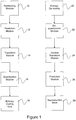
- the current picture or frame in a sequence of pictures is passed to a partitioning module 10 where it is partitioned into blocks of a given size for sequential processing by the encoder.
- Each block is then input to a prediction module 12, which seeks to discard temporal and spatial redundancies present in the sequence and obtain a prediction signal using previously coded content. Any information necessary to compute such prediction is encoded in the bit stream.
- the prediction signal is subtracted from the original signal to obtain a residual signal.
- This is then input to a transform module 14, which attempts to further reduce spatial redundancies within a block by using a more suitable representation of the data.
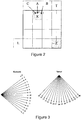
- FIG. 2 and 3 illustrate in more detail example prediction techniques that may be used in embodiments of the invention.
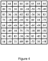
- Figure 4 illustrates by way of example a base matrix for an 8 x 8 transform unit.
- the decoding process illustrated on the right hand side of Figure 1 is essentially the reverse process.
- a received bit stream is decoded in module 20 to obtain a block of coefficients and the information necessary to compute the prediction for the current block.
- the block of coefficients is de-quantised in dequantisation module 22 and inverse transformed to the spatial domain by transform unit 24.
- a prediction signal is generated as before, from previously decoded samples from current or previous frames and using the information decoded from the bit stream, by prediction module 26.
- An original picture block is then reconstructed from the decoded residual signal and the calculated prediction block in the reconstruction block 28.
- the prediction module 12 of a video encoder provides the prediction signal for a given block.
- the way this prediction is computed depends on the current coding conditions, such as the temporal order of the current frame in the sequence or the coding configuration, and is generally based on rate-distortion decisions. There are a number of different ways that the prediction signal may be generated, as is well known in the art.
- intra-prediction methods make use of content extracted from the same frame as the currently encoded block. Usually only information extracted from samples in the surroundings of the current block being encoded are used to compute the prediction. This kind of prediction is generally useful in the case of high spatial correlation within the current picture, or when the content in the frame is the only available information (e.g. while encoding the first frame in the sequence).
- inter-prediction methods make use of the content of previously encoded frames (such as neighbouring frames in the sequence).
- the content of these frames can be very similar to the content of the current frame.
- Most of the encoders available today perform inter-prediction by means of motion estimation and compensation: the current picture block is compared with candidate prediction blocks extracted at certain spatial displacements from a previously encoded reference frame; for each candidate prediction block a distortion value is computed to measure the similarity between the two blocks; finally the candidate at minimum distortion is extracted to form the prediction for the current block.
- the information needed by the decoder to select and extract the correct prediction is included in the bit stream transmitted from the encoder, referred to as motion information.
- This residual signal is input to the transform module 14 to obtain a more compact representation. In general this is achieved by transforming the signal to the frequency domain, using a discrete cosine transform (DCT) or other process, to condense most of the information in a small number of coefficients suitable for a compact representation. Quantisation is applied on transform coefficients which reduces their precision to achieve desired high compression. Finally the obtained residual coefficients are entropy coded in the bit stream by Entropy Coding Unit 16.
- DCT discrete cosine transform
- Conventional intra-prediction methods typically compute the prediction block using a number of spatial samples extracted from the boundaries of the currently encoded picture block. To ensure that the process can be repeated at the decoder side, only samples in blocks that have already been encoded can be used for this purpose. For instance an encoder that processes blocks in raster scan order can only use samples in the top-left portion of the frame.
- samples are extrapolated from data in the boundary according to a certain specified angular direction. Different angular directions can be used to extrapolate samples at the boundary throughout the block. In the case of HEVC up to 33 directions (or modes) can be considered .
- FIG. 2 The process of obtaining the angular prediction is illustrated in Figure 2 .
- the encoder is trying to compute the sample in the location denoted as X in the figure.
- X is predicted using the samples located in A and C.
- the DC intra-prediction mode (referred to as mode 1 in HEVC) consists in predicting all samples in the prediction block using the same value, usually obtained by averaging a number of samples extracted from the boundary. This mode is suitable to predict very smooth areas of static content in the frame, but fails in providing a good prediction on content presenting higher frequency components.
- planar intra-prediction mode can be used. It has already been introduced in the AVC standard and is also used in HEVC. Planar prediction is based on successive interpolations of samples.
- the version currently implemented in the HEVC standard (referred to as mode 0) can be summarised as follows, again with the help of Figure 2 .
- the sample in location Z (at the bottom-right position in the block) is predicted as the arithmetic average of the sample in L (extracted from the boundary in the top-right location), and in T (extracted from the boundary in the bottom-left location).
- the right-most column and bottom-most row are predicted using bilinear interpolation between samples in T and Z, or in L and Z respectively. All other samples are predicted by means of bilinear interpolation using a combination of previously predicted samples and boundary samples.
- HEVC intra-prediction algorithms typically include a filtering algorithm usually applied to the samples in the boundary prior to performing intra-prediction.
- HEVC makes use of a smoothing filter, consisting of a gradient-based smoothing (for vertical or horizontal prediction) or a two-tap filtering (for DC prediction).
- transform encoding With reference to Figure 4 , the concept of transform encoding will now be discussed.
- the main idea behind transform coding is that of compacting the information in the signal in a smaller number of parameters by transforming it to the frequency domain.
- the transform should be able to decorrelate the signal as much as possible, obtaining a representation that is optimal for the purpose of data compression.
- each block of N x N pixel intensities is expressed as a weighted sum of N 2 scaled cosinusoids of different amplitudes and frequencies, referred to as the DCT basis functions.
- the weights that must be applied to each basis function in order to return exactly the original signal are referred to as the transformed coefficients.
- each following value of m and n corresponds to a higher frequency component AC(m, n), as illustrated in Figure 4 .
- Each transformed coefficient X(m, n) can be determined in terms of an inverse expression as a function of the original elements x(i, j). As a result, each block of N x N samples in the spatial domain is exactly represented by its corresponding block of N x N coefficients in the frequency domain.
- the elements in the base matrices used to compute the transform are obtained by means of rounded integer approximations of the values obtained using Equation 2 above.
- the transform coding is most effective in blocks that contain a relatively small amount of texture changes. In these cases the majority of coefficients at higher frequencies would be equal or close to zero while most of the signal would be compacted in a few coefficients at lower frequencies. It is therefore crucial that a frame is partitioned into blocks specifically for transform coding in the most efficient possible way.
- TU transform units
- a single base matrix Q 32 is defined for the largest allowed TU size (set at 32 x 32 pixels), obtained by appropriately rounding to integer approximations the values in Equation. 2.
- the base matrices for smaller TU sizes are obtained by downsampling this largest base matrix.
- the matrix Q 8 used for 8 x 8 TUs is illustrated in Figure 4 .
- the DCT has many desirable characteristics (such as ease of computation and very good performances for inter-predicted blocks), but it is not the optimal choice to decorrelate the residual signal especially in the case of intra-predicted blocks. This is due to the fact that its cosinusoidal basis functions are bad approximations of the behavior of the residual signal.
- angular prediction Samples in locations closer to the top or left boundaries are likely to be predicted more accurately than samples close to the bottom right corner of the block. Consequently, the residuals are likely to assume smaller values along the top row and right column in the block, and progressively larger values towards the left and bottom edges of the block.
- DST discrete sine transform
- Transform is followed by quantization.
- Each coefficient is quantized to a given step (depending on a parameter usually referred to as the quantization parameter, QP). The higher the QP, the coarser is the quantization. Coefficients that are closer to zero, usually corresponding to the higher frequency components, are completely discarded.
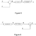
- Figure 5 illustrates how the processes are put together in a more mathematical sense in a known encoder.
- N x N square block of original samples X is being encoded.
- P is being considered as a predictor or prediction block for X, obtained from one of the possible intra-prediction modes.
- Q the N x N transform base matrix.
- this corresponds to an appropriately sized N-point DCT or DST transform matrix.
- the coded coefficients C that are extracted from the bitstream are dequantised to give a residual signal R , which is then inverse transformed into the spatial domain into the signal R , before being added to the prediction block P. This process is illustrated in Figure 6 .
- the prediction samples are transformed to the frequency domain, added to the dequantised coefficients, and finally the reconstructed samples are inverse transformed as in Figure 8 .
- Operating in the frequency domain allows the example embodiment of the invention to more easily manipulate the frequency coefficients prior to encoding in a way that provides advantages over the prior art. This will be discussed in more detail below.
- the example embodiment of the invention seeks to provide a more efficient prediction block for the encoding process as will be described below.
- a better encoder performance can be expected (due to the smaller residual samples which require less bits to be coded).
- common distortion metrics in the spatial domain such as the sum of squared differences (SSD) can be used to estimate the accuracy of a prediction
- SSD sum of squared differences
- these types of metrics can fail in measuring the impact of prediction methods on the residual coefficients at different frequency components. It is instead reasonable to expect particular effects of certain prediction modes on specific frequency components of the residual signal. These effects might be captured and analysed to formulate appropriate processing methods to improve the coding efficiency.
- K N,s denotes the number of N x N blocks tested using the intra-prediction mode s
- R N,s [m n] close to +1 indicate that the intra-prediction mode s is good at predicting the coefficient located in [m, n] when the TU size is N x N.
- Values of the cross-correlation close to zero indicate instead that the predicted samples in [m, n] carry almost no information on the original samples.
- the correlation results for TUs of different sizes are shown in Tables 2 for the planar intra-prediction mode; We have found that the TU size has a strong impact on the correlation values especially at higher frequencies (i.e. towards the bottom-right corner of the blocks). Relatively high correlation values are reported in 4 x 4 blocks at all locations (minimum correlation of 0.3), whereas very low correlation values were found in larger block sizes, showing that the prediction coefficients at these locations carry almost no information about the original coefficients. Similarly the correlation values are strongly influenced by the intra-prediction mode, as illustrated in Table 3. The correlation values for three angular modes are shown in the case of 8 x 8 blocks.
- the prediction coefficients in the locations with very low correlation with the original signal are discarded and replaced with more informative content generated by applying a number of value substitution processes.
- Some high frequency components can therefore be removed from the residual signal providing higher compression efficiency.
- each mask is a matrix of binary elements that can be applied to a block of coefficients; the value of a binary element in a certain location determines whether the corresponding coefficient in the block is preserved or discarded.
- the approach was implemented again in the context of the HEVC codec, but the method can be implemented in any video codec making use of block-based hybrid scheme.
- the size of the mask within the block can be varied as appropriate. Also, it will be appreciated that other shapes may be possible, depending on the coding circumstances.
- the masks shown in Figure 9 should therefore be taken as illustrations only.
- the shaded areas correspond to a first region of the prediction block in which the prediction coefficients are left unchanged.
- the white, or unshaded areas correspond to a second region of the prediction block in which the prediction coefficients are substituted or replaced.
- the encoder determines the optimal mask or pattern for a particular size of transform unit, the encoder continues to select this pattern when ever a transform unit of that size is encountered.
- This technique results in an improvement in encoding efficiency, and means that there is no need to continuously signal to the decoder which masks or patterns are used.
- the encoder can signal the preferred masks or patterns to the decoder once it has performed its initial analysis, and the decoder can store the required information for prediction block processing, or the decoder can also perform the same analysis as the encoder and store the results for future use.
- the original signal can contain large amount of details or textured areas, resulting in many non-zero components at high frequencies.
- typical conventional intra-prediction modes result in many zero-valued components at high frequencies (for example, the DC prediction mode returns a single non-zero coefficient, and similarly pure horizontal or vertical angular predictions return a single column or row of non-zero valued coefficients), and consequently high frequency components are often left in the residual signal.
- These sparse non-zero residual coefficients at high frequencies are extremely expensive to encode using conventional entropy coding methods. When targeting medium quality applications such coefficients are quantised and discarded, but in the case of high quality video coding this is not allowed. Higher coding efficiency is therefore achieved by removing these coefficients from the residual signal prior to quantization.
- a very good prediction can be obtained in the transformed domain using the best mask or pattern for each particular block, and replacing the coefficients that are discarded with values that are as close as possible to those in the same locations in the original transformed block.
- the use of a mask or pattern and/or the appropriate substitution of coefficients in a region of the preduction block not covered by the mask will be generally termed a modification process.
- the encoder according to the example embodiment of the invention may be implemented to test all possible candidates of modification process (varying both masks and coefficient substitution) for a particular transformed prediction block and select the optimal candidate. In practice, however, allowing both the choice of the pattern and the values to be used in place of the discarded coefficients can lead to delays in encoding, and might not result in efficient compression due to the large amount of information that would need to be processed and transmitted for each block.
- the pattern to use on a block is not transmitted, but is instead fixed depending on characteristics of the block such as size and intra-prediction mode.
- the encoder and the decoder may then simply look up the appropriate mask to use according to the coding circumstances using identical look up tables.
- these values are extracted from a look-up table that has been generated to contain suitable candidate values.
- a look-up table that has been generated to contain suitable candidate values.
- these values are extracted from a look-up table that has been generated to contain suitable candidate values.
- the number of elements in the look-up tables as low as possible, very few bits are needed to extract the correct element for each block.
- testing several candidates for the values of r[m, n] allow the encoder to flexibly choose the candidate that better predicts the original signal in each particular case.
- the proposed method can be used in any video codec making use of the block-based hybrid approach, testing and validation of the approach was obtained again implementing the method on top of conventional HEVC.
- the patterns in Table 4 i.e. the most frequently selected patterns obtained when zeroing-out components
- the elements in the look-up tables were similarly derived following from extensive empirical analysis.
- a look up table was generated with all possible candidate values that could be employed, for example, positive and negative integers ranging from 0 to 64. These look-up tables were then tested against actual TUs and masks and filtered to remove candidate values that were rarely found to give the optimal coding. In most cases, a look up table containing between 8 and 16 values was found to be more than sufficient to provide suitable candidate values.
- An example look up table is included as Figure 10 for illustration. It will be appreciated that the look up table is merely one way of retaining for a given prediction mode and TU size a set of candidate values for coefficient substitution. Other ways are performing coefficient substitution are possible.
- matrices would be formed of pre-computed, coefficients which replace the existing coefficients in the prediction signal.
- the area that we modified is formed of 4x8 samples.
- the encoder would test all the available matrices before selecting the optimal one. The corresponding index would be transmitted to the decoder.
- the set of matrices should be made available at both the encoder and decoder side.
- look-up tables are therefore derived and used depending on TU size and intra-prediction mode.
- the number of elements in the tables depends on the TU size, with fewer values allowed for tables used in case of 8 x 8 TUs, and increasingly more values in tables used for larger transform sizes. Once derived, such tables are then made available at both the encoder and decoder side.
- the encoder does not need to transmit information to the decoder specifying which mask or patterns and/or which substitution technique for the prediction coefficients are used, in more complex embodiments the encoder may calculate for every individual transform unit partitioned from an original block, the optimal mask or pattern, and the optimal coefficient values for substitution. In this case, it is useful if the encoder calculates the cost of transmitting the necessary information to the decoder to indicate which pattern or mask, and/or which coefficient substituion technique was selected, and factor this into its selection decision.
- any information transmitted to the decoder to indicate the selected compression scheme will count as extra transmission overhead and so will impact the amount of picture data that can be transmitted and/or the quality of the transmitted data.
- the encoder may use a rate distortion optimisation technique to determine which modification process and signalling scheme to indicate the selected modification process is optimal.
- Rate distortion techniques combine a distortion metric, such as SSD, SAD or normalised cross-correlation, with an estimated bitrate necessary to signal to the decoder the required information to described the modification process.
- Estimates can be produced by way of known fast estimation methods which return a figure for the number of bits needed to encode the index associated with the current pattern, or alternately, the encoder could in fact perform the actual coding method it would use to transmit the picture information and signalling information to the decoder, and then feedback the exact number of bits required to the decision process.
- the encoder would compute the RD cost for each modification process extracted from the list of considered patterns, and select the pattern at minimum cost.
- each TU is encoded using the proposed method and testing all of the elements in the appropriate look-up table.
- the same TU is also encoded using conventional HEVC, and finally the best solution in a RD sense is selected and signalled in the bitstream.
- the algorithm can be summarised as follows.
- the reconstruction block is computed using the inverse process and compared with the original block to obtain a distortion.
- the RD cost is computed for this solution.
- a novel approach for efficiently coding video sequences in high quality conditions has therefore been presented based on frequency domain prediction methods.
- Conventional intra-prediction techniques often fail in providing good prediction of the original signal, especially at higher frequencies and when using large transform sizes.
- high quality applications it is crucial that these high frequency components are not quantised and discarded, and for this reason conventional video coding methods result in very high bitrates.
- the proposed method allows instead to adaptively replace the high frequency components in the prediction signal, possibly resulting in smaller residual coefficients without any loss of data.
- the approach is based on a modified encoder scheme where original and prediction signal are independently transformed to the frequency domain; this is opposite to conventional schemes where the residual block is computed in the spatial domain and successively transformed.
- the proposed encoder scheme allows for an additional stage of processing, introduced at the encoder side after the prediction is transformed, and prior to the residual calculation.
- the processing is based on a set of masking patterns applied to the transformed prediction block. Each pattern identifies which coefficients in the prediction signal are discarded, and which coefficients are instead preserved. Coefficients that are discarded are replaced with constant values extracted from lookup tables, appropriately derived depending on the transform size and intra-prediction mode.
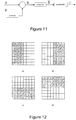
- Figure 11 illustrates the process of calculating the residual signal, transforming this, and quantising this for transmission in a bit stream.
- the arrangement is identical to the prior art situation of Figure 5 , except that the prediction block P is processed in the spatial domain before being subtracted from the original block.
- a number of possible patterns or masks are applied to the prediction block.
- Example mask or patterns for the processing step are illustrated in Figure 12 as masks, a, b, c and d.
- the size of the mask within the block can be varied as appropriate. Also, it will be appreciated that other shapes may be possible, depending on the coding conditions.
- the shaded areas correspond to a first region of the prediction block in which the prediction coefficients are left unchanged.
- the white, or unshaded areas correspond to a second region of the prediction block in which the prediction coefficients are substituted or replaced.
- the coefficients to be substituted are spatial domain samples corresponding to pixel intensities.
- the modification of the samples in the prediction block can be carried out in a number of different ways, all with the purpose of ensuring that the coding of the resulting residual signal is carried out more efficiently.
- one way is by using a substitution mechanism similar to the one used in the frequency domain and illustrated in Figure 10 .
- look-up tables might be used which replace the selected samples in the prediction block with synthetic samples, and associate each of these elements with an index that can be signalled to the decoder side.
- the samples in the prediction block are representative of pixel intensities, and the term synthentic samples is used to suggest that the values substituted are scaled to match values in the range of pixel intensities in the prediction block, but are otherwise selected by the modification process.
- an example of such a table is illustrated in Figure 13 .
- the decoding process for the spatial domain is shown in Figure 14 , and is similar to that of Figure 6 for the frequency domain.
- the coefficients in the second region of the mask that are substituted or replaced may be substituted or replaced with values that are a combination of the initial prediction coefficient and the predetermined substitution value.
- a weighted combination of the initial prediction value and the predetemined substitution value could be used.
- the processing of the prediction block carried out in both the frequency and the spatial domains is generally a separate step carried out after the prediction block has been calculated in the normal way by the encoder or the decoder.
- the prior art encoder and decoder schemes of Figures 1 and 2 can be thought of as having a modification processing block situated after the prediction module that receives the formed or generated prediction block and applies the modification process accordingly. This is in fact illustrated in Figures 7, 8 , 11 and 14 .
- the prediction module itself may be modified to generate a prediction block having the necessary modifications made to improve the efficiency of the encoding.
- the principle would be the same as described above, with generation of a prediction block having two regions, a first region in which the coefficients are standard coefficients generated from known prediction modes and methods, and a second region in which the coefficients are generated by an algorithm taking into account a value substitution, either substitution in the case of replacement with predetemined values or a combination of values.
- the first and second set of predetermined locations are exclusive of one another.
- the regions may overlap, such that the substituted values are combinations of predicted values and predetermined values for substitution.
- Table 1 Binary Shifts in Conventional HEVC for 8 bit data representation TU Size Bin. Shift First DCT stage 4 x 4 >> 1 8 x 8 >> 2 16 x 16 >> 3 32 x 32 >> 4 Second DCT stage 4 x 4 >> 8 8 x 8 >> 9 16 x 16 >> 10 32 x 32 >> 11
- Table 2 Selected values of the cross-correlation for blocks of different sizes intra-predicted user planar mode.
Landscapes
- Engineering & Computer Science (AREA)
- Multimedia (AREA)
- Signal Processing (AREA)
- Compression Or Coding Systems Of Tv Signals (AREA)
Claims (14)
- Verfahren zum Encodieren von Videodaten mit Kompression, das Folgendes beinhaltet:a) Empfangen eines ursprünglichen Bildblocks, der Samples enthält;b) Erzeugen eines Prädiktionsblocks, das Folgendes beinhaltet:b1) Erzeugen, in einer Raumdomäne, eines Samples enthaltenden Prädiktionsblocks gemäß einem Intra-Prädiktions- oder Inter-Prädiktionscodierschema; und Transformieren des ursprünglichen Bildblocks und des Prädiktionsblocks in eine zweite Domäne;b2) Konservieren von Koeffizienten in einem ersten Satz von vorbestimmten Positionen in dem Prädiktionsblock; undb3) Ersetzen von Koeffizienten in einem zweiten Satz von vorbestimmten Positionen in dem Prädiktionsblock gemäß einem Koeffizientensubstitutionsprozess mit gemäß einem vorbestimmten Algorithmus berechneten Werten; undc) Berechnen eines Restsignals zur Übertragung durch Subtrahieren des ursprünglichen Bildblocks und des Prädiktionsblocks voneinander;wobei der Koeffizientensubstitutionsprozess und das Berechnen des Restsignals in der zweiten Domäne erfolgen.
- Verfahren nach Anspruch 1, wobei der Sample-Substitutionsprozess eines oder mehrere der Folgenden beinhaltet:i) Setzen eines Koeffizienten auf einen Wert von null;ii) Setzen eines Koeffizienten auf einen vorbestimmten Wert von ungleich null.
- Verfahren nach Anspruch 1 oder 2, wobei die Positionen im Prädiktionsblock, die im ersten und zweiten Satz von vorbestimmten Positionen sind, und/oder der Koeffizientensubstitutionsprozess von einem oder mehreren aus Form und/oder Größe des Prädiktionsblocks und dem zum Erzeugen des Prädiktionsblocks benutzten Prädiktionsencodierschema abhängig ist/sind.
- Verfahren nach einem der Ansprüche 1 bis 3, das Folgendes beinhaltet:Transformieren des ursprünglichen Bildblocks und des Prädiktionsblocks in die Frequenzdomäne; undBilden des modifizierten Prädiktionsblocks und Berechnen des Restsignals in der Frequenzdomäne.
- Verfahren nach einem der Ansprüche 1 bis 4, das Folgendes beinhaltet:g) Berechnen des Prädiktionsfehlers zwischen dem Prädiktionsblock und dem ursprünglichen Bildblock;h) Erzeugen eines zweiten und nachfolgenden Prädiktionsblocks, wobei beim Erzeugen des zweiten Prädiktionsblocks der Koeffizientensubstitutionsprozess und/oder die Positionen des Prädiktionsblocks im ersten und zweiten Satz von vorbestimmten Positionen variiert/-en, um mehrere verschiedene modifizierte Kandidaten-Prädiktionsblöcke zu erzeugen;i) Berechnen, für jeden der mehreren verschiedenen modifizierten Kandidaten-Prädiktionsblöcke, des Prädiktionsfehlers zwischen dem jeweiligen modifizierten Kandidaten-Prädiktionsblock und dem ursprünglichen Bildblock; undj) Auswählen von einem der mehreren verschiedenen modifizierten Kandidaten-Prädiktionsblöcke zur Verwendung beim Berechnen des Restsignals auf der Basis des Prädiktionsfehlers.
- Verfahren zum Decodieren von Videodaten mit Kompression, das Folgendes beinhaltet:a) Empfangen eines encodierten Restsignals;b) Erzeugen eines Prädiktionsblocks, das Folgendes beinhaltet:b1) Erzeugen, in einer Raumdomäne, eines Samples enthaltenden Prädiktionsblocks gemäß einem Intra-Prädiktions- oder Inter-Prädiktionscodierschema; und Transformieren des Prädiktionsblocks in eine zweite Domäne;b2) Konservieren von Koeffizienten an einem ersten Satz von vorbestimmten Positionen in dem Prädiktionsblock; undb3) Ersetzen von Koeffizienten an einem zweiten Satz von vorbestimmten Positionen in dem Prädiktionsblock gemäß einem Koeffizientensubstitutionsprozess mit gemäß einem vorbestimmten Algorithmus berechneten Werten; undc) Berechnen, in der zweiten Domäne, eines ursprünglichen Bildblocks durch Hinzufügen des Restsignals und des Prädiktionsblocks zueinander.
- Verfahren nach Anspruch 6, wobei der Koeffizientensubstitutionsprozess eines oder mehrere der Folgenden beinhaltet:i) Setzen eines Koeffizienten auf einen Wert von null;ii) Setzen eines Koeffizienten auf einen vorbestimmten Wert von ungleich null.
- Verfahren nach Anspruch 6 oder 7, wobei die Positionen im Prädiktionsblock, die im ersten und zweiten Satz von vorbestimmten Positionen sind, und/oder der Koeffizientensubstitutionsprozess von einem oder mehreren aus Form und/oder Größe des Prädiktionsblocks und dem zum Erzeugen des Prädiktionsblocks benutzten Prädiktionsencodierschema abhängig sind.
- Verfahren nach Anspruch 6, 7 oder 8, das Folgendes beinhaltet:
Erzeugen des Prädiktionsblocks in der Frequenzdomäne und Berechnen des rekonstruierten Blocks in der Frequenzdomäne. - Verfahren nach einem der Ansprüche 6 bis 9, das Folgendes beinhaltet:Empfangen, als Bitstrom, des encodierten Restsignals und eines Indexes, der einen Modifikationsprozess anzeigt, der am Encoder zum Modifizieren des Prädiktionsblocks benutzt wird; undAuswählen von einer oder mehreren der Positionen in dem Prädiktionsblock, die im ersten und zweiten Satz von vorbestimmten Positionen sind, und/oder des Koeffizientensubstitutionsprozesses auf der Basis des empfangenen Indexes.
- Verfahren nach Anspruch 6, das Folgendes beinhaltet:Empfangen, als Bitstrom, des encodierten Restsignals und eines Indexes, der einen Modifikationsprozess anzeigt, der am Encoder zum Modifizieren des für Encodierung benutzten Prädiktionsblocks benutzt wird; undSetzen der Koeffizienten im zweiten Satz von vorbestimmten Positionen auf der Basis einer Nachschlag-Tabelle, die mehrere Kandidatenwerte enthält, wobei Elemente aus den Nachschlag-Tabellen auf der Basis des empfangenen Indexes extrahiert werden.
- Computerlesbares Medium, auf dem Computercode gespeichert ist, der bei Ausführung durch einen Computerprozessor bewirkt, dass der Computerprozessor die Schritte nach einem der Ansprüche 1 bis 11 durchführt.
- Video-Encoder, der Folgendes umfasst:a) eine Partitionseinheit (10) zum Ausgeben eines ursprünglichen Bildblocks;b) eine Prädiktionseinheit (12) zum Erzeugen eines Prädiktionsblocks, wobei die Prädiktionseinheit (12) konfiguriert ist zum:b1) Erzeugen, in einer Raumdomäne, eines Samples enthaltenden Prädiktionsblocks gemäß einem Intra-Prädiktions- oder Inter-Prädiktionscodierschema; und Transformieren des ursprünglichen Bildblocks und des Prädiktionsblocks in eine zweite Domäne;b2) Konservieren von Koeffizienten in einem ersten Satz von vorbestimmten Positionen in dem Prädiktionsblock; undb3) Ersetzen von Koeffizienten in einem zweiten Satz von vorbestimmten Positionen in dem Prädiktionsblock gemäß einem Koeffizientensubstitutionsprozess mit gemäß einem vorbestimmten Algorithmus berechneten Werten; undc) einen Rechenblock zum Berechnen eines Restsignals zur Übertragung durch Subtrahieren des ursprünglichen Bildblocks und des Prädiktionsblocks voneinander;wobei die Prädiktionseinheit (12) zum Durchführen des Koeffizientensubstitutionsprozesses und zum Berechnen des Restsignals in der zweiten Domäne konfiguriert ist.
- Video-Decoder, der Folgendes umfasst:a) einen Empfänger zum Empfangen eines encodierten Restsignals;b) eine Prädiktionseinheit zum Erzeugen des Prädiktionsblocks, wobei die Prädiktionseinheit konfiguriert ist zum:b1) Erzeugen, in einer Raumdomäne, eines Samples enthaltenden Prädiktionsblocks gemäß einem Intra-Prädiktions- oder Inter-Prädiktionscodierschema; und Transformieren des Prädiktionsblocks in eine zweite Domäne;b2) Konservieren von Koeffizienten in einem ersten Satz von vorbestimmten Positionen in dem Prädiktionsblock; undb3) Ersetzen von Koeffizienten in einem zweiten Satz von vorbestimmten Positionen in dem Prädiktionsblock gemäß einem Koeffizientensubstitutionsprozess mit gemäß einem vorbestimmten Algorithmus berechneten Werten; undc) eine Recheneinheit zum Berechnen, in der zweiten Domäne, eines ursprünglichen Bildblocks durch Hinzufügen des Restsignals und des Prädiktionsblocks zueinander.
Applications Claiming Priority (2)
| Application Number | Priority Date | Filing Date | Title |
|---|---|---|---|
| GB1319493.1A GB2520002B (en) | 2013-11-04 | 2013-11-04 | An improved compression algorithm for video compression codecs |
| PCT/EP2014/073712 WO2015063330A1 (en) | 2013-11-04 | 2014-11-04 | Adaptive prediction of coefficients of a video block |
Publications (2)
| Publication Number | Publication Date |
|---|---|
| EP3066832A1 EP3066832A1 (de) | 2016-09-14 |
| EP3066832B1 true EP3066832B1 (de) | 2020-04-29 |
Family
ID=49767669
Family Applications (1)
| Application Number | Title | Priority Date | Filing Date |
|---|---|---|---|
| EP14795808.6A Active EP3066832B1 (de) | 2013-11-04 | 2014-11-04 | Adaptive prädiktion von koeffizienten von videoblöcken |
Country Status (4)
| Country | Link |
|---|---|
| US (1) | US11134242B2 (de) |
| EP (1) | EP3066832B1 (de) |
| GB (1) | GB2520002B (de) |
| WO (1) | WO2015063330A1 (de) |
Families Citing this family (12)
| Publication number | Priority date | Publication date | Assignee | Title |
|---|---|---|---|---|
| FR3044507A1 (fr) * | 2015-11-30 | 2017-06-02 | Orange | Procede de codage et de decodage d'images, dispositif de codage et de decodage d'images et programmes d'ordinateur correspondants |
| US10469841B2 (en) * | 2016-01-29 | 2019-11-05 | Google Llc | Motion vector prediction using prior frame residual |
| US10306258B2 (en) | 2016-01-29 | 2019-05-28 | Google Llc | Last frame motion vector partitioning |
| CN109716762B (zh) * | 2016-09-20 | 2023-06-09 | 株式会社Kt | 用于处理视频信号的方法 |
| GB2574733B (en) | 2016-12-28 | 2020-05-06 | Arris Entpr Llc | Improved video bitstream coding |
| US10593122B1 (en) * | 2017-01-24 | 2020-03-17 | Amazon Technologies, Inc. | Mirroring edge pixels |
| US10580167B1 (en) * | 2017-01-24 | 2020-03-03 | Amazon Technologies, Inc. | Excluding masked regions of virtual reality (VR) frames from encoder processing |
| US10574997B2 (en) * | 2017-10-27 | 2020-02-25 | Apple Inc. | Noise level control in video coding |
| WO2019127358A1 (en) * | 2017-12-29 | 2019-07-04 | Intel Corporation | Modular motion estimation engine for tree-based video |
| GB2580084B (en) * | 2018-12-20 | 2022-12-28 | Canon Kk | Video coding and decoding |
| CN113518227B (zh) * | 2020-04-09 | 2023-02-10 | 于江鸿 | 数据处理的方法和系统 |
| EP4714117A1 (de) * | 2023-05-17 | 2026-03-25 | Nokia Technologies Oy | Vorrichtung, verfahren und computerprogramm zur videocodierung und -decodierung |
Family Cites Families (11)
| Publication number | Priority date | Publication date | Assignee | Title |
|---|---|---|---|---|
| US6341144B1 (en) | 1996-09-20 | 2002-01-22 | At&T Corp. | Video coder providing implicit coefficient prediction and scan adaptation for image coding and intra coding of video |
| DE69929660T2 (de) * | 1999-08-31 | 2006-08-17 | Lucent Technologies Inc. | Verfahren und Vorrichtung für Makroblock DC- und AC-Koefficienten-Prädiktion in Videocodierung |
| KR101108681B1 (ko) * | 2005-01-19 | 2012-01-25 | 삼성전자주식회사 | 동영상 코덱에서의 주파수 변환 계수 예측 방법 및 장치,이를 구비한 부호화 및 복호화 장치와 방법 |
| EP2182732A1 (de) * | 2008-10-28 | 2010-05-05 | Panasonic Corporation | Umschalten zwischen Abtastungsresultaten bei der Bildkodierung |
| KR101675116B1 (ko) * | 2009-08-06 | 2016-11-10 | 삼성전자 주식회사 | 영상의 부호화 방법 및 장치, 그 복호화 방법 및 장치 |
| US9313526B2 (en) * | 2010-02-19 | 2016-04-12 | Skype | Data compression for video |
| RU2573216C2 (ru) * | 2010-06-04 | 2016-01-20 | Сони Корпорейшн | Устройство и способ обработки изображений |
| CN103069798B (zh) | 2010-06-29 | 2016-12-21 | 法国电信 | 用于在实施变换域估计过程中对至少一个图像进行编码和解码的方法和装置 |
| GB2481856A (en) * | 2010-07-09 | 2012-01-11 | British Broadcasting Corp | Picture coding using weighted predictions in the transform domain |
| KR101483179B1 (ko) * | 2010-10-06 | 2015-01-19 | 에스케이 텔레콤주식회사 | 주파수 마스크 테이블을 이용한 주파수변환 블록 부호화 방법 및 장치와 그를 이용한 영상 부호화/복호화 방법 및 장치 |
| RU2597509C2 (ru) * | 2012-02-29 | 2016-09-10 | Сони Корпорейшн | Устройство и способ обработки изображений |
-
2013
- 2013-11-04 GB GB1319493.1A patent/GB2520002B/en active Active
-
2014
- 2014-11-04 US US15/034,057 patent/US11134242B2/en active Active
- 2014-11-04 WO PCT/EP2014/073712 patent/WO2015063330A1/en not_active Ceased
- 2014-11-04 EP EP14795808.6A patent/EP3066832B1/de active Active
Non-Patent Citations (1)
| Title |
|---|
| None * |
Also Published As
| Publication number | Publication date |
|---|---|
| EP3066832A1 (de) | 2016-09-14 |
| GB201319493D0 (en) | 2013-12-18 |
| US20160269725A1 (en) | 2016-09-15 |
| GB2520002A (en) | 2015-05-13 |
| WO2015063330A1 (en) | 2015-05-07 |
| US11134242B2 (en) | 2021-09-28 |
| GB2520002B (en) | 2018-04-25 |
Similar Documents
| Publication | Publication Date | Title |
|---|---|---|
| US11134242B2 (en) | Adaptive prediction of coefficients of a video block | |
| US11438618B2 (en) | Method and apparatus for residual sign prediction in transform domain | |
| US11240496B2 (en) | Low complexity mixed domain collaborative in-loop filter for lossy video coding | |
| CN104067619B (zh) | 视频解码器、视频解码方法以及视频解码程序的记录介质 | |
| EP1256238B1 (de) | Videokodierung und -dekodierung, bewegungskompensiertervideokoder und zugehöriger dekoder | |
| US8126053B2 (en) | Image encoding/decoding method and apparatus | |
| US8995778B2 (en) | Method and apparatus for encoding/decoding high resolution images | |
| EP2629523B1 (de) | Videokomprimierung | |
| US9438905B2 (en) | LM mode with uniform bit-width multipliers | |
| EP2520093B1 (de) | Datenkomprimierung für videoinhalte | |
| EP3316580A2 (de) | Verfahren und vorrichtung zur codierung oder decodierung eines bildes | |
| US20090225834A1 (en) | Method and apparatus for image intra prediction | |
| EP3140988B1 (de) | Verfahren und vorrichtung zur reduzierung einer rechnerlast in einer hocheffizienten videokodierung | |
| US20110206132A1 (en) | Data Compression for Video | |
| US9838690B1 (en) | Selective prediction signal filtering | |
| US9877025B2 (en) | Video encoding and decoding with prediction at higher precision | |
| WO2008020687A1 (en) | Image encoding/decoding method and apparatus | |
| WO2008004768A1 (en) | Image encoding/decoding method and apparatus | |
| WO2007108642A1 (en) | Image encoding/decoding method and apparatus | |
| US20240031580A1 (en) | Method and apparatus for video coding using deep learning based in-loop filter for inter prediction | |
| KR20170084213A (ko) | 디지털 이미지의 블록을 처리하는 시스템 및 방법 | |
| US11265575B2 (en) | Image and video processing apparatuses and methods | |
| US20230199196A1 (en) | Methods and Apparatuses of Frequency Domain Mode Decision in Video Encoding Systems | |
| KR102966326B1 (ko) | 비디오 코딩을 위한 방법 및 장치 | |
| US20200329232A1 (en) | Method and device for encoding or decoding video signal by using correlation of respective frequency components in original block and prediction block |
Legal Events
| Date | Code | Title | Description |
|---|---|---|---|
| PUAI | Public reference made under article 153(3) epc to a published international application that has entered the european phase |
Free format text: ORIGINAL CODE: 0009012 |
|
| 17P | Request for examination filed |
Effective date: 20160606 |
|
| AK | Designated contracting states |
Kind code of ref document: A1 Designated state(s): AL AT BE BG CH CY CZ DE DK EE ES FI FR GB GR HR HU IE IS IT LI LT LU LV MC MK MT NL NO PL PT RO RS SE SI SK SM TR |
|
| AX | Request for extension of the european patent |
Extension state: BA ME |
|
| DAX | Request for extension of the european patent (deleted) | ||
| STAA | Information on the status of an ep patent application or granted ep patent |
Free format text: STATUS: EXAMINATION IS IN PROGRESS |
|
| 17Q | First examination report despatched |
Effective date: 20170818 |
|
| GRAJ | Information related to disapproval of communication of intention to grant by the applicant or resumption of examination proceedings by the epo deleted |
Free format text: ORIGINAL CODE: EPIDOSDIGR1 |
|
| STAA | Information on the status of an ep patent application or granted ep patent |
Free format text: STATUS: GRANT OF PATENT IS INTENDED |
|
| GRAP | Despatch of communication of intention to grant a patent |
Free format text: ORIGINAL CODE: EPIDOSNIGR1 |
|
| INTG | Intention to grant announced |
Effective date: 20191122 |
|
| GRAS | Grant fee paid |
Free format text: ORIGINAL CODE: EPIDOSNIGR3 |
|
| GRAA | (expected) grant |
Free format text: ORIGINAL CODE: 0009210 |
|
| STAA | Information on the status of an ep patent application or granted ep patent |
Free format text: STATUS: THE PATENT HAS BEEN GRANTED |
|
| AK | Designated contracting states |
Kind code of ref document: B1 Designated state(s): AL AT BE BG CH CY CZ DE DK EE ES FI FR GR HR HU IE IS IT LI LT LU LV MC MK MT NL NO PL PT RO RS SE SI SK SM TR |
|
| RBV | Designated contracting states (corrected) |
Designated state(s): AL AT BE BG CH CY CZ DE DK EE ES FI FR GR HR HU IE IS IT LI LT LU LV MC MK MT NL NO PL PT RO RS SE SI SK SM TR |
|
| REG | Reference to a national code |
Ref country code: CH Ref legal event code: EP |
|
| REG | Reference to a national code |
Ref country code: AT Ref legal event code: REF Ref document number: 1265087 Country of ref document: AT Kind code of ref document: T Effective date: 20200515 |
|
| REG | Reference to a national code |
Ref country code: DE Ref legal event code: R096 Ref document number: 602014064601 Country of ref document: DE |
|
| REG | Reference to a national code |
Ref country code: IE Ref legal event code: FG4D |
|
| REG | Reference to a national code |
Ref country code: NL Ref legal event code: MP Effective date: 20200429 |
|
| REG | Reference to a national code |
Ref country code: LT Ref legal event code: MG4D |
|
| PG25 | Lapsed in a contracting state [announced via postgrant information from national office to epo] |
Ref country code: FI Free format text: LAPSE BECAUSE OF FAILURE TO SUBMIT A TRANSLATION OF THE DESCRIPTION OR TO PAY THE FEE WITHIN THE PRESCRIBED TIME-LIMIT Effective date: 20200429 Ref country code: LT Free format text: LAPSE BECAUSE OF FAILURE TO SUBMIT A TRANSLATION OF THE DESCRIPTION OR TO PAY THE FEE WITHIN THE PRESCRIBED TIME-LIMIT Effective date: 20200429 Ref country code: PT Free format text: LAPSE BECAUSE OF FAILURE TO SUBMIT A TRANSLATION OF THE DESCRIPTION OR TO PAY THE FEE WITHIN THE PRESCRIBED TIME-LIMIT Effective date: 20200831 Ref country code: IS Free format text: LAPSE BECAUSE OF FAILURE TO SUBMIT A TRANSLATION OF THE DESCRIPTION OR TO PAY THE FEE WITHIN THE PRESCRIBED TIME-LIMIT Effective date: 20200829 Ref country code: NO Free format text: LAPSE BECAUSE OF FAILURE TO SUBMIT A TRANSLATION OF THE DESCRIPTION OR TO PAY THE FEE WITHIN THE PRESCRIBED TIME-LIMIT Effective date: 20200729 Ref country code: SE Free format text: LAPSE BECAUSE OF FAILURE TO SUBMIT A TRANSLATION OF THE DESCRIPTION OR TO PAY THE FEE WITHIN THE PRESCRIBED TIME-LIMIT Effective date: 20200429 Ref country code: GR Free format text: LAPSE BECAUSE OF FAILURE TO SUBMIT A TRANSLATION OF THE DESCRIPTION OR TO PAY THE FEE WITHIN THE PRESCRIBED TIME-LIMIT Effective date: 20200730 |
|
| REG | Reference to a national code |
Ref country code: AT Ref legal event code: MK05 Ref document number: 1265087 Country of ref document: AT Kind code of ref document: T Effective date: 20200429 |
|
| PG25 | Lapsed in a contracting state [announced via postgrant information from national office to epo] |
Ref country code: BG Free format text: LAPSE BECAUSE OF FAILURE TO SUBMIT A TRANSLATION OF THE DESCRIPTION OR TO PAY THE FEE WITHIN THE PRESCRIBED TIME-LIMIT Effective date: 20200729 Ref country code: RS Free format text: LAPSE BECAUSE OF FAILURE TO SUBMIT A TRANSLATION OF THE DESCRIPTION OR TO PAY THE FEE WITHIN THE PRESCRIBED TIME-LIMIT Effective date: 20200429 Ref country code: HR Free format text: LAPSE BECAUSE OF FAILURE TO SUBMIT A TRANSLATION OF THE DESCRIPTION OR TO PAY THE FEE WITHIN THE PRESCRIBED TIME-LIMIT Effective date: 20200429 Ref country code: LV Free format text: LAPSE BECAUSE OF FAILURE TO SUBMIT A TRANSLATION OF THE DESCRIPTION OR TO PAY THE FEE WITHIN THE PRESCRIBED TIME-LIMIT Effective date: 20200429 |
|
| PG25 | Lapsed in a contracting state [announced via postgrant information from national office to epo] |
Ref country code: NL Free format text: LAPSE BECAUSE OF FAILURE TO SUBMIT A TRANSLATION OF THE DESCRIPTION OR TO PAY THE FEE WITHIN THE PRESCRIBED TIME-LIMIT Effective date: 20200429 Ref country code: AL Free format text: LAPSE BECAUSE OF FAILURE TO SUBMIT A TRANSLATION OF THE DESCRIPTION OR TO PAY THE FEE WITHIN THE PRESCRIBED TIME-LIMIT Effective date: 20200429 |
|
| PG25 | Lapsed in a contracting state [announced via postgrant information from national office to epo] |
Ref country code: ES Free format text: LAPSE BECAUSE OF FAILURE TO SUBMIT A TRANSLATION OF THE DESCRIPTION OR TO PAY THE FEE WITHIN THE PRESCRIBED TIME-LIMIT Effective date: 20200429 Ref country code: AT Free format text: LAPSE BECAUSE OF FAILURE TO SUBMIT A TRANSLATION OF THE DESCRIPTION OR TO PAY THE FEE WITHIN THE PRESCRIBED TIME-LIMIT Effective date: 20200429 Ref country code: DK Free format text: LAPSE BECAUSE OF FAILURE TO SUBMIT A TRANSLATION OF THE DESCRIPTION OR TO PAY THE FEE WITHIN THE PRESCRIBED TIME-LIMIT Effective date: 20200429 Ref country code: IT Free format text: LAPSE BECAUSE OF FAILURE TO SUBMIT A TRANSLATION OF THE DESCRIPTION OR TO PAY THE FEE WITHIN THE PRESCRIBED TIME-LIMIT Effective date: 20200429 Ref country code: SM Free format text: LAPSE BECAUSE OF FAILURE TO SUBMIT A TRANSLATION OF THE DESCRIPTION OR TO PAY THE FEE WITHIN THE PRESCRIBED TIME-LIMIT Effective date: 20200429 Ref country code: CZ Free format text: LAPSE BECAUSE OF FAILURE TO SUBMIT A TRANSLATION OF THE DESCRIPTION OR TO PAY THE FEE WITHIN THE PRESCRIBED TIME-LIMIT Effective date: 20200429 Ref country code: EE Free format text: LAPSE BECAUSE OF FAILURE TO SUBMIT A TRANSLATION OF THE DESCRIPTION OR TO PAY THE FEE WITHIN THE PRESCRIBED TIME-LIMIT Effective date: 20200429 Ref country code: RO Free format text: LAPSE BECAUSE OF FAILURE TO SUBMIT A TRANSLATION OF THE DESCRIPTION OR TO PAY THE FEE WITHIN THE PRESCRIBED TIME-LIMIT Effective date: 20200429 |
|
| REG | Reference to a national code |
Ref country code: DE Ref legal event code: R097 Ref document number: 602014064601 Country of ref document: DE |
|
| PG25 | Lapsed in a contracting state [announced via postgrant information from national office to epo] |
Ref country code: PL Free format text: LAPSE BECAUSE OF FAILURE TO SUBMIT A TRANSLATION OF THE DESCRIPTION OR TO PAY THE FEE WITHIN THE PRESCRIBED TIME-LIMIT Effective date: 20200429 Ref country code: SK Free format text: LAPSE BECAUSE OF FAILURE TO SUBMIT A TRANSLATION OF THE DESCRIPTION OR TO PAY THE FEE WITHIN THE PRESCRIBED TIME-LIMIT Effective date: 20200429 |
|
| PLBE | No opposition filed within time limit |
Free format text: ORIGINAL CODE: 0009261 |
|
| STAA | Information on the status of an ep patent application or granted ep patent |
Free format text: STATUS: NO OPPOSITION FILED WITHIN TIME LIMIT |
|
| 26N | No opposition filed |
Effective date: 20210201 |
|
| PG25 | Lapsed in a contracting state [announced via postgrant information from national office to epo] |
Ref country code: SI Free format text: LAPSE BECAUSE OF FAILURE TO SUBMIT A TRANSLATION OF THE DESCRIPTION OR TO PAY THE FEE WITHIN THE PRESCRIBED TIME-LIMIT Effective date: 20200429 |
|
| PG25 | Lapsed in a contracting state [announced via postgrant information from national office to epo] |
Ref country code: MC Free format text: LAPSE BECAUSE OF FAILURE TO SUBMIT A TRANSLATION OF THE DESCRIPTION OR TO PAY THE FEE WITHIN THE PRESCRIBED TIME-LIMIT Effective date: 20200429 |
|
| REG | Reference to a national code |
Ref country code: CH Ref legal event code: PL |
|
| PG25 | Lapsed in a contracting state [announced via postgrant information from national office to epo] |
Ref country code: LU Free format text: LAPSE BECAUSE OF NON-PAYMENT OF DUE FEES Effective date: 20201104 |
|
| REG | Reference to a national code |
Ref country code: BE Ref legal event code: MM Effective date: 20201130 |
|
| PG25 | Lapsed in a contracting state [announced via postgrant information from national office to epo] |
Ref country code: CH Free format text: LAPSE BECAUSE OF NON-PAYMENT OF DUE FEES Effective date: 20201130 Ref country code: LI Free format text: LAPSE BECAUSE OF NON-PAYMENT OF DUE FEES Effective date: 20201130 |
|
| PG25 | Lapsed in a contracting state [announced via postgrant information from national office to epo] |
Ref country code: IE Free format text: LAPSE BECAUSE OF NON-PAYMENT OF DUE FEES Effective date: 20201104 |
|
| PG25 | Lapsed in a contracting state [announced via postgrant information from national office to epo] |
Ref country code: TR Free format text: LAPSE BECAUSE OF FAILURE TO SUBMIT A TRANSLATION OF THE DESCRIPTION OR TO PAY THE FEE WITHIN THE PRESCRIBED TIME-LIMIT Effective date: 20200429 Ref country code: MT Free format text: LAPSE BECAUSE OF FAILURE TO SUBMIT A TRANSLATION OF THE DESCRIPTION OR TO PAY THE FEE WITHIN THE PRESCRIBED TIME-LIMIT Effective date: 20200429 Ref country code: CY Free format text: LAPSE BECAUSE OF FAILURE TO SUBMIT A TRANSLATION OF THE DESCRIPTION OR TO PAY THE FEE WITHIN THE PRESCRIBED TIME-LIMIT Effective date: 20200429 |
|
| PG25 | Lapsed in a contracting state [announced via postgrant information from national office to epo] |
Ref country code: MK Free format text: LAPSE BECAUSE OF FAILURE TO SUBMIT A TRANSLATION OF THE DESCRIPTION OR TO PAY THE FEE WITHIN THE PRESCRIBED TIME-LIMIT Effective date: 20200429 |
|
| PG25 | Lapsed in a contracting state [announced via postgrant information from national office to epo] |
Ref country code: BE Free format text: LAPSE BECAUSE OF NON-PAYMENT OF DUE FEES Effective date: 20201130 |
|
| P01 | Opt-out of the competence of the unified patent court (upc) registered |
Effective date: 20230330 |
|
| PGFP | Annual fee paid to national office [announced via postgrant information from national office to epo] |
Ref country code: FR Payment date: 20250908 Year of fee payment: 12 |
|
| PGFP | Annual fee paid to national office [announced via postgrant information from national office to epo] |
Ref country code: DE Payment date: 20250910 Year of fee payment: 12 |