EP3066955A1 - Système de bac à emboîtement empilable - Google Patents
Système de bac à emboîtement empilable Download PDFInfo
- Publication number
- EP3066955A1 EP3066955A1 EP16152918.5A EP16152918A EP3066955A1 EP 3066955 A1 EP3066955 A1 EP 3066955A1 EP 16152918 A EP16152918 A EP 16152918A EP 3066955 A1 EP3066955 A1 EP 3066955A1
- Authority
- EP
- European Patent Office
- Prior art keywords
- sidewall
- tray
- coupled
- trays
- adjacent
- Prior art date
- Legal status (The legal status is an assumption and is not a legal conclusion. Google has not performed a legal analysis and makes no representation as to the accuracy of the status listed.)
- Withdrawn
Links
Images


Classifications
-
- B—PERFORMING OPERATIONS; TRANSPORTING
- B65—CONVEYING; PACKING; STORING; HANDLING THIN OR FILAMENTARY MATERIAL
- B65D—CONTAINERS FOR STORAGE OR TRANSPORT OF ARTICLES OR MATERIALS, e.g. BAGS, BARRELS, BOTTLES, BOXES, CANS, CARTONS, CRATES, DRUMS, JARS, TANKS, HOPPERS, FORWARDING CONTAINERS; ACCESSORIES, CLOSURES, OR FITTINGS THEREFOR; PACKAGING ELEMENTS; PACKAGES
- B65D21/00—Nestable, stackable or joinable containers; Containers of variable capacity
- B65D21/02—Containers specially shaped, or provided with fittings or attachments, to facilitate nesting, stacking, or joining together
- B65D21/0209—Containers specially shaped, or provided with fittings or attachments, to facilitate nesting, stacking, or joining together stackable or joined together one-upon-the-other in the upright or upside-down position
- B65D21/0224—Auxiliary removable stacking elements other than covers
-
- A—HUMAN NECESSITIES
- A47—FURNITURE; DOMESTIC ARTICLES OR APPLIANCES; COFFEE MILLS; SPICE MILLS; SUCTION CLEANERS IN GENERAL
- A47B—TABLES; DESKS; OFFICE FURNITURE; CABINETS; DRAWERS; GENERAL DETAILS OF FURNITURE
- A47B87/00—Sectional furniture, i.e. combinations of complete furniture units, e.g. assemblies of furniture units of the same kind such as linkable cabinets, tables, racks or shelf units
- A47B87/02—Sectional furniture, i.e. combinations of complete furniture units, e.g. assemblies of furniture units of the same kind such as linkable cabinets, tables, racks or shelf units stackable ; stackable and linkable
- A47B87/0207—Stackable racks, trays or shelf units
- A47B87/0246—Shelves stackable by means of separate vertical distance-holders therebetween
-
- B—PERFORMING OPERATIONS; TRANSPORTING
- B65—CONVEYING; PACKING; STORING; HANDLING THIN OR FILAMENTARY MATERIAL
- B65D—CONTAINERS FOR STORAGE OR TRANSPORT OF ARTICLES OR MATERIALS, e.g. BAGS, BARRELS, BOTTLES, BOXES, CANS, CARTONS, CRATES, DRUMS, JARS, TANKS, HOPPERS, FORWARDING CONTAINERS; ACCESSORIES, CLOSURES, OR FITTINGS THEREFOR; PACKAGING ELEMENTS; PACKAGES
- B65D1/00—Rigid or semi-rigid containers having bodies formed in one piece, e.g. by casting metallic material, by moulding plastics, by blowing vitreous material, by throwing ceramic material, by moulding pulped fibrous material or by deep-drawing operations performed on sheet material
- B65D1/34—Trays or like shallow containers
-
- B—PERFORMING OPERATIONS; TRANSPORTING
- B65—CONVEYING; PACKING; STORING; HANDLING THIN OR FILAMENTARY MATERIAL
- B65D—CONTAINERS FOR STORAGE OR TRANSPORT OF ARTICLES OR MATERIALS, e.g. BAGS, BARRELS, BOTTLES, BOXES, CANS, CARTONS, CRATES, DRUMS, JARS, TANKS, HOPPERS, FORWARDING CONTAINERS; ACCESSORIES, CLOSURES, OR FITTINGS THEREFOR; PACKAGING ELEMENTS; PACKAGES
- B65D21/00—Nestable, stackable or joinable containers; Containers of variable capacity
- B65D21/02—Containers specially shaped, or provided with fittings or attachments, to facilitate nesting, stacking, or joining together
- B65D21/0201—Containers specially shaped, or provided with fittings or attachments, to facilitate nesting, stacking, or joining together stackable or joined together side-by-side
- B65D21/0204—Containers specially shaped, or provided with fittings or attachments, to facilitate nesting, stacking, or joining together stackable or joined together side-by-side and joined together by interconnecting formations forming part of the container, e.g. dove-tail, snap connections, hook elements
-
- A—HUMAN NECESSITIES
- A47—FURNITURE; DOMESTIC ARTICLES OR APPLIANCES; COFFEE MILLS; SPICE MILLS; SUCTION CLEANERS IN GENERAL
- A47B—TABLES; DESKS; OFFICE FURNITURE; CABINETS; DRAWERS; GENERAL DETAILS OF FURNITURE
- A47B61/00—Wardrobes
- A47B61/04—Wardrobes for shoes, hats, umbrellas, or the like
Definitions
- This application generally relates to a tray system that allows a plurality of trays to be interlocked with one another and stacked in various configurations.
- trays may be utilized as placement of shoes such as work boots.
- the tray may form a protective barrier between the floor and objects (e.g., shoes) placed on the trays to reduce the chance of unwanted dirt, water, or debris from such objects contaminating the floor.
- Embodiments of the invention are directed to systems (e.g., apparatuses) and methods for providing stackable interlocking trays, the system includes various configurations of upper and lower tray assemblies that include one or more trays.
- the tray assemblies may be operatively coupled to one another via a support assembly that includes one or more struts.
- the present invention is advantageous because the stackable configuration allows for a reduction in space occupied by the trays. Furthermore, the design of the trays reduces the chance of unwanted dirt, water, or debris dripping from a tray onto a lower tray or surface.
- the present invention embraces a stackable interlocking tray system that includes a support assembly having a plurality of struts, wherein each of the plurality of struts define a first end and a second end.
- the stackable interlocking tray system also includes an upper tray assembly having one or more first trays operatively coupled to the support assembly.
- Each of the one or more first trays typically has a bottom surface having a plurality of lower attachment locations configured to be coupled with the first end of one of the plurality of struts.
- the stackable interlocking tray system includes a lower tray assembly having one or more second trays operatively coupled to the support assembly.
- Each of the one or more second trays may have a top surface having a plurality of upper attachment locations configured to be coupled with the second end of one of the plurality of struts.
- Each of the one or more first trays may include a plurality of sidewalls configured to be coupled with a complementary sidewall of an adjacent one of the first trays.
- each of the one or more second trays may include a plurality of sidewalls configured to be coupled with a complementary sidewall of an adjacent one of the second trays.
- each of the first trays may include a first sidewall, a second sidewall, a third sidewall, and a fourth sidewall, the first sidewall being configured to be coupled with the second sidewall of a first adjacent one of the first trays, the second sidewall being configured to be coupled with the first sidewall of a second adjacent one of the first trays, the third sidewall being configured to be coupled with the fourth sidewall of a third adjacent one of the first trays, the fourth sidewall being configured to be coupled with the third sidewall of a fourth adjacent one of the first trays.
- each of the second trays may include a first sidewall, a second sidewall, a third sidewall, and a fourth sidewall, the first sidewall being configured to be coupled with the second sidewall of a first adjacent one of the second trays, the second sidewall being configured to be coupled with the first sidewall of a second adjacent one of the second trays, the third sidewall being configured to be coupled with the fourth sidewall of a third adjacent one of the second trays, the fourth sidewall being configured to be coupled with the third sidewall of a fourth adjacent one of the second trays.
- the first sidewall may include a first hooking mechanism configured to be coupled with the second sidewall of the first adjacent one of the second trays
- the second sidewall may include a second hooking mechanism configured to be coupled with the first sidewall of the second adjacent one of the second trays
- the third sidewall may include a third hooking mechanism configured to be coupled with the fourth sidewall of the third adjacent one of the second trays
- the fourth sidewall may be configured to be coupled with the third hooking mechanism of the third sidewall of the fourth adjacent one of the second trays.
- each of the lower attachment locations may include a female receptacle configured for receiving the first end of one of the plurality of struts.
- the female receptacle of each of the lower attachment locations may define a recess configured for receiving the first end of one of the plurality of struts.
- each of the upper attachment locations may include a female receptacle configured for receiving the second end of one of the plurality of struts.
- the second end of each of the plurality of struts may include a plurality of protrusions
- the female receptacle of each of the upper attachment locations may define a plurality of slots, each slot being configured to receive one of the protrusions of the second end of one of the plurality of struts.
- the present invention embraces stackable interlocking tray that includes (i) a bottom surface, the bottom surface defining a plurality of lower attachment locations, each lower attachment location being configured to be coupled with a first end of a strut, and (ii) a top surface, the top surface defining a plurality of upper attachment locations, each upper attachment location being configured to be coupled with a second end of a strut.
- the stackable interlocking tray also includes (i) a first sidewall, the first sidewall being configured to be coupled with a second sidewall of a first adjacent tray, (ii) a second sidewall, the second sidewall being configured to be coupled with a first sidewall of a second adjacent tray, (iii) a third sidewall, the third sidewall being configured to be coupled with a fourth sidewall of a third adjacent tray, and (iv) a fourth sidewall, the fourth sidewall being configured to be coupled with a third sidewall of a fourth adjacent tray.
- the first sidewall may include a first hooking mechanism configured to be coupled with the second sidewall of the first adjacent tray, the first sidewall being configured to be coupled with a second hooking mechanism of the second sidewall of the first adjacent tray, and the second sidewall may include a second hooking mechanism configured to be coupled with the first sidewall of the second adjacent tray, the second sidewall being configured to be coupled with a first hooking mechanism of the first sidewall of the second adjacent tray.
- the third sidewall may include a third hooking mechanism configured to be coupled with the fourth sidewall of the third adjacent tray, and the fourth sidewall may be configured to be coupled with a third hooking mechanism of the third sidewall of the fourth adjacent tray
- each of the lower attachment locations may include a female receptacle configured for receiving a first end of a strut.
- the female receptacle of each of the lower attachment locations may define a recess configured for receiving a first end of a strut.
- each of the upper attachment locations may include a female receptacle configured for receiving a second end of a strut.
- the female receptacle of each of the upper attachment locations may define a plurality of slots, each slot being configured to receive a protrusion defined by a second end of a strut.
- the present invention embraces a stackable interlocking tray system.
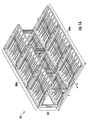
- Figures 1-9 illustrate an exemplary stackable interlocking tray system 100, and the various components thereof, in accordance with the present invention.
- the stackable interlocking tray system 100 includes, in general, three assemblies: (1) a base or lower tray assembly 200a, (2) an upper tray assembly 200b, and (3) a support assembly 300 that operatively couples the upper tray assembly 200b with the base tray assembly 200a.
- the various assemblies, and components thereof, of the stackable interlocking tray system 100 of Figure 1 are illustrated in Figures 2-9 and described in further detail throughout this specification.
- the lower tray assembly 200a is located at the base of the stackable interlocking tray system 100 and is configured to be implemented as the foundation of a plurality of tray configurations.
- the phrase stackable interlocking tray system 100 may refer to at least one of the lower tray assembly 200a or upper tray assembly 200b.
- the stackable interlocking tray system 100 may include only an upper tray assembly 200b that is upheld via the support assembly 300.
- the support assembly 300 may function as the sole foundation of the upper tray assembly 200b.
- the stackable interlocking tray system 100 may include only a lower tray assembly 200a.
- the components of the stackable interlocking tray system 100 may be formed of polyurethane, rubber, plastic, metal, or another suitable material not explicitly mentioned herein.
- the lower tray assembly 200a may include one or more trays 202 positioned at the base of the stackable interlocking tray system 100.
- the support assembly 300 may include one or more struts 302 that are securely positioned within a top surface of the one or more trays 202 and extend vertically upward, from the lower tray assembly 200a, in an upright orientation.
- the support assembly 300 (or additional components within) is configured for supporting the general structure of the stackable interlocking tray system 100, and is further configured to operatively couple the lower tray assembly 200a to the upper tray assembly 200b, which may include one or more trays 202 positioned at the top of the stackable interlocking tray system 100.
- the one or more struts 302 may extend upward towards the upper tray assembly 200b, and be further securely positioned within a bottom surface of the one or more trays 202 of the upper tray assembly 200b.
- the upper tray assembly 200b may be suspended above the lower tray assembly 200a in a horizontal orientation such that the lower and upper assemblies 200b, 200a are separated by a distance substantially defined by the height of the struts 302 of the support assembly 300.
- a tray 202 may be utilized in either the lower or upper tray assembly, 200a, 200b, respectively.
- any tray 202 within the lower tray assembly 200a typically may be interchanged with a tray within the upper tray assembly 200b, and vice versa, and achieve the same functional effect within the stackable interlocking tray system 100.
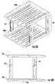
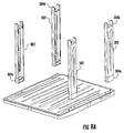
- FIGS 5A-5E illustrate a tray 202 according to various embodiments discussed herein. It should be noted that although in some embodiments the tray 202 is defined by a rectangular shape, the tray 202 may be embodied by other shapes that are not illustrated herein, including but not limited to, squared, circular, trapezoidal, and/or organic or ameba shapes.
- the tray 202 may generally include a top surface 202a and a bottom surface 202b.
- the bottom surface 202b may have a plurality of indentations 203 therein. These indentations 203 may provide a rigidness within the planar surface of the tray 202.
- the indentations 203 typically extend into the bottom surface 202b of the tray 203 such that they cause upward projections within the top surface 202a of the tray that form ridges 209. It should be noted that although in some embodiments the indentations 203 and ridges 209 are defined by a trapezoidal shape, the indentations may be embodied by other shapes that are not illustrated herein, including but not limited to, squared, circular, rectangular, and/or organic or ameba shapes. In other embodiments, the bottom surface 202b may lack indentations 203, but the top surface 202a may nevertheless define ridges 209.
- the tray may further include a left side wall 204a, right side wall 204b, rear side wall 204c, and front side wall 204d that extend upward from the bottom surface of the tray 202b. Furthermore, the front end of the left and right sidewalls 204a, 204b, respectively, may be angled such that the front end of the left and right sidewalls 204a, 204b is slanted downward and outward towards the front wall 204d of the tray 202.
- the tray 202 is typically configured to be coupled to one or more struts 302 for the purpose of stacking the lower and upper tray assemblies 200a, 200b, on top of one another. Accordingly, the top and bottom surfaces of the tray may define a plurality of attachment location each of which is configured to be coupled with a strut.
- the tray 202 may further include an upper receptacle region 205 and lower receptacle region 206 that lie along the top and bottom surfaces, respectively, of the left, right, and rear side walls 204a, 204b, 204c of the tray 202.
- the upper receptacle region 205 may further include a plurality of upper female receptacles 205a configured to receive a second male end 304b of a strut 302 such that the strut is coupled to the top surface of the tray 202.
- Each upper female receptacle 205a may be further defined by a plurality of slots 205b (e.g., two slots) within the receptacle region 205 that are positioned such that they are parallel to one another. These slots 205b are typically configured to receive corresponding protrusions on a second male end 304b of a strut 302.
- the tray 202 includes a first upper female receptacle 205a located at the front left side of the upper receptacle region 205, a second upper female receptacle 205a located at the rear left side of the upper receptacle region 205, a third upper female receptacle 205a located at the front right side of the upper receptacle region 205, and a fourth top female receptacle 205a located at the rear right side of the upper receptacle region 205.
- the tray 202 may be configured to receive four (4) struts 302 within the first, second, third, and fourth upper female receptacles 205a.
- the lower receptacle region 206 may further include a plurality of lower female receptacles 206a configured to receive a first male end 304a of a strut 302 such that the strut 302 is coupled to the bottom surface of the tray 202.
- Each lower female receptacles 206a typically defines a recess for receiving a first male end 304a of a strut 302.
- the tray 202 includes a first lower female receptacle 206a located at the front left side of the lower receptacle region 206, a second lower female receptacle 206a located at the rear left side of the lower receptacle region 206, a third lower female receptacle 206a located at the front right side of the lower receptacle region 206, and a fourth lower female receptacle 206a located at the rear right side of the lower receptacle region 206.
- the tray 202 may be configured to receive four (4) struts 302 within the first, second, third, and fourth female receptacles 206a.
- Each tray assembly may be formed from a plurality of adjacent interlocking trays. Accordingly, each of the sidewalls of the trays 202 is typically configured to be coupled with a complementary sidewall of an adjacent tray 202.
- a tray assembly may include trays 202 that horizontally interlock along axis X illustrated in Figure 1 . Accordingly, as shown in Figures 5A-5E , each tray 202 may define lateral side attachment regions 207a, 207b along the exterior edges of the left and right side walls 204a, 204b.
- Each lateral side attachment region 207a, 207b typically defines at least one hooking and/or clasp mechanism configured to engage a lateral side wall (e.g., a left or right side wall 204a, 204b) of an adjacent tray 202.
- the tray 202 includes a first attachment region 207a located at the exterior edge of a rear portion of the left side wall 204a, and a second attachment region 207b located at the exterior edge of a front portion of the right side wall 204b.
- the tray 202 may be configured to interlock with another tray 202 on both its left and right sides, and so the outermost edges 208 of the left and right side wall 204a, 204b may be sized and shaped such that the edges 208 are configured to be coupled to the lateral side attachment regions 207a, 207b to interconnect adjacent trays 202 (e.g., such that the trays 202 are securely attached to one another).
- a lateral side attachment region 207b along a right side wall 204b of a first tray 202 may engage a left side wall 204a of a second tray 202
- a lateral side attachment region 207a along the left side wall 204a of the second tray 202 may engage the right side wall 204b of the first tray 202.
- at least a portion of the interlocked trays 202 typically overlap one another such that at least a portion of the attachment regions 207a, 207b extend upward into the bottom surface of an adjacent tray.
- Each tray assembly may also include trays 202 that horizontally interlock along axis Y illustrated in Figure 1 .
- the front side of each tray 202 may be configured to be coupled to a rear side of an adjacent tray, and the rear side of each tray 202 may be configured to be coupled to a front side of an adjacent tray.
- the rear side wall 204c of each tray 202 may define a rear attachment region 207c that is configured to be coupled with the front side wall 204d of an adjacent tray 202.
- the rear attachment region 207c typically defines at least one hooking and/or clasp mechanism configured to engage the front side wall 204d of an adjacent tray 202.
- the rear attachment region 207c may extend along the length of the rear side wall 204c of each tray 202.
- the tray 202 may be configured to interlock with another tray 202 on both its front and rear sides, and so the front side wall 204d of each tray 204 may be sized and shaped to engage the rear attachment region 207c of an adjacent tray 202 (e.g., such that the trays 202 are securely attached to one another).
- the front side wall 204d of a particular tray may engage a hooking mechanism of the rear attachment region 207c of an adjacent tray so that the rear attachment region 207c of the adjacent tray overlaps the front side wall 204d and extends downward into the top surface of the particular tray.
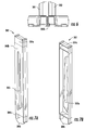
- Figures 7A-7B illustrates a strut 302 according to various embodiments discussed herein.
- the strut 302 may be embodied by other shapes that are not illustrated herein, including but not limited to, squared, cylindrical, trapezoidal, and/or organic or ameba shapes.
- the strut 302 may generally include an inner surface 302a and an outer surface 302b having an indentation 303 therein.
- the struts 302 may be embodied by any individual members that can be coupled with a tray 202 using a fastener and/or another suitable coupling mechanism (e.g. a snap fit, screw, or the like).
- the strut 302 includes a first male end 304a that is configured to engage a lower female receptacle 206a of a tray 202 in order to couple the strut 302 to the bottom surface 202b of such tray 202.
- the first male end 304a and a lower female receptacle 206a of a tray 202 may form a snap fit that securely couples the strut 302 to such tray 202.
- Figure 9C depicts the first male end 304a engaging a lower female receptacle 206a of a tray 202.
- the strut 302 typically also includes a second male end 304b that is configured to engage an upper female receptacle 205a of a tray 202 in order to couple the strut 302 to the top surface 202a of such tray 202.
- the second male end 304b may define protrusions 304c (e.g., parallel protrusions) that engage corresponding slots 205b of an upper female receptacle 205a of a tray 202.
- These protrusions 304c may form a snap with corresponding slots 205b of an upper female receptacle 205a of a tray 202 to securely couple the strut 302 to such tray 202.
- Figure 9D depicts the second male end 304b engaging an upper female receptacle 205a of a tray 202.
- the first male end 304a of a strut 302 may be coupled to a bottom surface 202b of a tray 202 of an upper tray assembly 200b
- the second male end 304b of the strut 302 may be coupled to a top surface 202a of a tray 202 of a lower tray assembly 200a.
- multiple struts 302 e.g., four struts
- an interlocking tray system 400 includes a single tray assembly 400a.
- each tray 402 typically is configured to be coupled to one or more additional trays for the purpose of horizontally expanding the tray assembly 400a.
- each side wall 404a, 404b, 404c, 404d of the tray 402 is configured to engage a complementary side wall of an adjacent tray 402.
- the right side wall 404b and the front side wall 404d may each define a coupling mechanism 407 (e.g., a hooking and/or clasp mechanism) along their exterior edges.
- the coupling mechanisms 407 of the right side wall 404b and the front side wall 404d are typically configured to engage, respectively, a left side wall 404a and a rear side wall 404c of adjacent trays 402.
- the coupling mechanisms 407 may be sized and shaped to overlap a complementary side wall (e.g., a left side wall 404a or a rear side wall 404a of an adjacent tray) and extends downward into the top surface of an adjacent tray.
- the top edges of the left and rear side walls 404a, 404c may be sized and shaped such that the edges of these side walls are configured to be positioned within the coupling mechanisms 407 of the right front side walls 404b, 404d, respectively, to interlock one or more trays 402 such that the trays are securely attached to one another.
- the tray 402 may be configured to interlock with another tray 402 on multiple sides.
- Figure 11 illustrates the corners of four different trays 402 being connected together.
- the tray 402 may form ridges similar to those on the trays 202 illustrated in Figures 1-9 . In contrast with the trays 202 illustrated in Figures 1-9 , the trays 402 might not be configured to be attached to a strut for the purpose of vertically expanding the tray system 400.
Landscapes
- Engineering & Computer Science (AREA)
- Mechanical Engineering (AREA)
- Ceramic Engineering (AREA)
- Stackable Containers (AREA)
- Warehouses Or Storage Devices (AREA)
Applications Claiming Priority (1)
| Application Number | Priority Date | Filing Date | Title |
|---|---|---|---|
| US201562108981P | 2015-01-28 | 2015-01-28 |
Publications (1)
| Publication Number | Publication Date |
|---|---|
| EP3066955A1 true EP3066955A1 (fr) | 2016-09-14 |
Family
ID=55361325
Family Applications (1)
| Application Number | Title | Priority Date | Filing Date |
|---|---|---|---|
| EP16152918.5A Withdrawn EP3066955A1 (fr) | 2015-01-28 | 2016-01-27 | Système de bac à emboîtement empilable |
Country Status (3)
| Country | Link |
|---|---|
| US (1) | US20160214763A1 (fr) |
| EP (1) | EP3066955A1 (fr) |
| CA (1) | CA2919176C (fr) |
Families Citing this family (6)
| Publication number | Priority date | Publication date | Assignee | Title |
|---|---|---|---|---|
| CA2955891C (fr) * | 2017-01-24 | 2018-01-02 | Sebastien Lassonde | Etagere et support a chaussures servant a evacuer l'eau des chaussures mouillees |
| US10092099B1 (en) * | 2017-09-14 | 2018-10-09 | Ronald Linari | Adjustable shelving |
| US20210094727A1 (en) * | 2018-02-13 | 2021-04-01 | Envases Chiloe S.A. | Arrangement of expanded polystyrene boxes and expanded polystyrene box for food transport and storage |
| CN113135334A (zh) * | 2021-04-12 | 2021-07-20 | 深圳市中孚能电气设备有限公司 | 一种托盘架 |
| US20230182982A1 (en) * | 2021-10-21 | 2023-06-15 | Marine Lumber Co. | Pallet system |
| USD1115407S1 (en) * | 2023-06-20 | 2026-03-03 | Guangdong Haixing Plastic & Rubber Co., Ltd. | Shoe rack |
Citations (3)
| Publication number | Priority date | Publication date | Assignee | Title |
|---|---|---|---|---|
| US6079339A (en) * | 1998-05-26 | 2000-06-27 | Rubbermaid Incorporated | Shelving system |
| US20080053940A1 (en) * | 2006-08-18 | 2008-03-06 | John Whalen | Inverted cell honeycomb structure shelving |
| US20090242501A1 (en) * | 2007-01-19 | 2009-10-01 | Rubbermaid Incorporated | Shelving unit |
Family Cites Families (12)
| Publication number | Priority date | Publication date | Assignee | Title |
|---|---|---|---|---|
| US863536A (en) * | 1906-04-21 | 1907-08-13 | Edward A Hudson | Skillet. |
| US3857482A (en) * | 1973-11-12 | 1974-12-31 | R Shelton | Display tray |
| US4429796A (en) * | 1980-01-28 | 1984-02-07 | Howard Sussman | Interconnected one-piece desk unit |
| US4467927A (en) * | 1982-08-12 | 1984-08-28 | Walter Nathan | Molded tray for display stands |
| US4930643A (en) * | 1987-11-02 | 1990-06-05 | Paul Flum Ideas, Inc. | Display unit with modular capability |
| US4873921A (en) * | 1988-07-14 | 1989-10-17 | Piane Caterers, Inc. | Multiple unit wok apparatus |
| US5158187A (en) * | 1991-03-15 | 1992-10-27 | Taub Ronald H | Tray of shelf-like structure |
| US5265735A (en) * | 1991-11-19 | 1993-11-30 | Microcomputer Accessories, Inc. | Modular desktop organizer for use with computer keyboard |
| US5588541A (en) * | 1994-10-05 | 1996-12-31 | Alco Industries, Inc. | Heavy-duty decorative shelving |
| US5683004A (en) * | 1996-05-22 | 1997-11-04 | Structural Plastics Corporation | Stackable and unstackable support construction |
| US9896244B2 (en) * | 2014-05-09 | 2018-02-20 | Enpac, L.L.C. | Linkable workstations |
| US9364084B2 (en) * | 2014-06-04 | 2016-06-14 | Vishal Durgadutt Rege | Two-tiered boot tray with umbrella drip tray stand |
-
2016
- 2016-01-27 US US15/008,170 patent/US20160214763A1/en not_active Abandoned
- 2016-01-27 EP EP16152918.5A patent/EP3066955A1/fr not_active Withdrawn
- 2016-01-28 CA CA2919176A patent/CA2919176C/fr active Active
Patent Citations (3)
| Publication number | Priority date | Publication date | Assignee | Title |
|---|---|---|---|---|
| US6079339A (en) * | 1998-05-26 | 2000-06-27 | Rubbermaid Incorporated | Shelving system |
| US20080053940A1 (en) * | 2006-08-18 | 2008-03-06 | John Whalen | Inverted cell honeycomb structure shelving |
| US20090242501A1 (en) * | 2007-01-19 | 2009-10-01 | Rubbermaid Incorporated | Shelving unit |
Also Published As
| Publication number | Publication date |
|---|---|
| CA2919176A1 (fr) | 2016-07-28 |
| US20160214763A1 (en) | 2016-07-28 |
| CA2919176C (fr) | 2025-05-06 |
Similar Documents
| Publication | Publication Date | Title |
|---|---|---|
| EP3066955A1 (fr) | Système de bac à emboîtement empilable | |
| US20140106108A1 (en) | Building blocks | |
| US6607199B2 (en) | Tray and dolly assembly | |
| US9474374B2 (en) | Modular shelving | |
| US20170339916A1 (en) | Kit for modular housing for cats | |
| CA2782659C (fr) | Systeme et bloc de mur de soutenement | |
| JP5631777B2 (ja) | 組立・分解可能容器 | |
| US8424689B2 (en) | Modular rack system | |
| CA2866790A1 (fr) | Plateau de boulangerie | |
| US8789475B1 (en) | Pallet guard terminator | |
| CA3057203C (fr) | Labyrinthe empilable pour petit animal | |
| KR200473792Y1 (ko) | 무볼트 조립식 앵글 구조 | |
| AU2011301168A1 (en) | Bulk bin | |
| US20090302725A1 (en) | Modular Storage System | |
| JP2012166842A (ja) | 嵩上げ可能容器 | |
| KR200482453Y1 (ko) | 개선된 조립식구조와 전면 마감구조를 갖는 납골 안치단 | |
| CN102233967B (zh) | 用于置物盒的支撑柱 | |
| JP2001187610A (ja) | 流動棚 | |
| US8881326B2 (en) | Modular infant furniture and connectors therefor | |
| JP2014156286A (ja) | 嵩上げ可能容器 | |
| JP3187776U (ja) | 陳列台 | |
| JP6501502B2 (ja) | 棚板 | |
| JP5360395B2 (ja) | ラックの棚板支持構造 | |
| US10010197B1 (en) | Document holding apparatus | |
| AU2006292022B2 (en) | Modular storage system |
Legal Events
| Date | Code | Title | Description |
|---|---|---|---|
| PUAI | Public reference made under article 153(3) epc to a published international application that has entered the european phase |
Free format text: ORIGINAL CODE: 0009012 |
|
| AK | Designated contracting states |
Kind code of ref document: A1 Designated state(s): AL AT BE BG CH CY CZ DE DK EE ES FI FR GB GR HR HU IE IS IT LI LT LU LV MC MK MT NL NO PL PT RO RS SE SI SK SM TR |
|
| AX | Request for extension of the european patent |
Extension state: BA ME |
|
| STAA | Information on the status of an ep patent application or granted ep patent |
Free format text: STATUS: REQUEST FOR EXAMINATION WAS MADE |
|
| 17P | Request for examination filed |
Effective date: 20170307 |
|
| RBV | Designated contracting states (corrected) |
Designated state(s): AL AT BE BG CH CY CZ DE DK EE ES FI FR GB GR HR HU IE IS IT LI LT LU LV MC MK MT NL NO PL PT RO RS SE SI SK SM TR |
|
| GRAP | Despatch of communication of intention to grant a patent |
Free format text: ORIGINAL CODE: EPIDOSNIGR1 |
|
| STAA | Information on the status of an ep patent application or granted ep patent |
Free format text: STATUS: GRANT OF PATENT IS INTENDED |
|
| INTG | Intention to grant announced |
Effective date: 20170825 |
|
| STAA | Information on the status of an ep patent application or granted ep patent |
Free format text: STATUS: THE APPLICATION IS DEEMED TO BE WITHDRAWN |
|
| 18D | Application deemed to be withdrawn |
Effective date: 20180105 |