EP3067005B1 - Laserchirurgievorrichtung für kontaktlaserchirurgie - Google Patents
Laserchirurgievorrichtung für kontaktlaserchirurgie Download PDFInfo
- Publication number
- EP3067005B1 EP3067005B1 EP15000757.3A EP15000757A EP3067005B1 EP 3067005 B1 EP3067005 B1 EP 3067005B1 EP 15000757 A EP15000757 A EP 15000757A EP 3067005 B1 EP3067005 B1 EP 3067005B1
- Authority
- EP
- European Patent Office
- Prior art keywords
- laser
- tissue
- fiber
- scalpel
- fiber tip
- Prior art date
- Legal status (The legal status is an assumption and is not a legal conclusion. Google has not performed a legal analysis and makes no representation as to the accuracy of the status listed.)
- Active
Links
Images


Classifications
-
- A—HUMAN NECESSITIES
- A61—MEDICAL OR VETERINARY SCIENCE; HYGIENE
- A61F—FILTERS IMPLANTABLE INTO BLOOD VESSELS; PROSTHESES; DEVICES PROVIDING PATENCY TO, OR PREVENTING COLLAPSING OF, TUBULAR STRUCTURES OF THE BODY, e.g. STENTS; ORTHOPAEDIC, NURSING OR CONTRACEPTIVE DEVICES; FOMENTATION; TREATMENT OR PROTECTION OF EYES OR EARS; BANDAGES, DRESSINGS OR ABSORBENT PADS; FIRST-AID KITS
- A61F9/00—Methods or devices for treatment of the eyes; Devices for putting in contact-lenses; Devices to correct squinting; Apparatus to guide the blind; Protective devices for the eyes, carried on the body or in the hand
- A61F9/007—Methods or devices for eye surgery
- A61F9/008—Methods or devices for eye surgery using laser
- A61F9/00821—Methods or devices for eye surgery using laser for coagulation
-
- A—HUMAN NECESSITIES
- A61—MEDICAL OR VETERINARY SCIENCE; HYGIENE
- A61N—ELECTROTHERAPY; MAGNETOTHERAPY; RADIATION THERAPY; ULTRASOUND THERAPY
- A61N5/00—Radiation therapy
- A61N5/06—Radiation therapy using light
- A61N5/0613—Apparatus adapted for a specific treatment
- A61N5/0625—Warming the body, e.g. hyperthermia treatment
-
- A—HUMAN NECESSITIES
- A61—MEDICAL OR VETERINARY SCIENCE; HYGIENE
- A61B—DIAGNOSIS; SURGERY; IDENTIFICATION
- A61B18/00—Surgical instruments, devices or methods for transferring non-mechanical forms of energy to or from the body
- A61B18/18—Surgical instruments, devices or methods for transferring non-mechanical forms of energy to or from the body by applying electromagnetic radiation, e.g. microwaves
- A61B18/20—Surgical instruments, devices or methods for transferring non-mechanical forms of energy to or from the body by applying electromagnetic radiation, e.g. microwaves using laser
- A61B18/203—Surgical instruments, devices or methods for transferring non-mechanical forms of energy to or from the body by applying electromagnetic radiation, e.g. microwaves using laser applying laser energy to the outside of the body
-
- A—HUMAN NECESSITIES
- A61—MEDICAL OR VETERINARY SCIENCE; HYGIENE
- A61F—FILTERS IMPLANTABLE INTO BLOOD VESSELS; PROSTHESES; DEVICES PROVIDING PATENCY TO, OR PREVENTING COLLAPSING OF, TUBULAR STRUCTURES OF THE BODY, e.g. STENTS; ORTHOPAEDIC, NURSING OR CONTRACEPTIVE DEVICES; FOMENTATION; TREATMENT OR PROTECTION OF EYES OR EARS; BANDAGES, DRESSINGS OR ABSORBENT PADS; FIRST-AID KITS
- A61F9/00—Methods or devices for treatment of the eyes; Devices for putting in contact-lenses; Devices to correct squinting; Apparatus to guide the blind; Protective devices for the eyes, carried on the body or in the hand
- A61F9/007—Methods or devices for eye surgery
- A61F9/008—Methods or devices for eye surgery using laser
- A61F9/00802—Methods or devices for eye surgery using laser for photoablation
-
- A—HUMAN NECESSITIES
- A61—MEDICAL OR VETERINARY SCIENCE; HYGIENE
- A61F—FILTERS IMPLANTABLE INTO BLOOD VESSELS; PROSTHESES; DEVICES PROVIDING PATENCY TO, OR PREVENTING COLLAPSING OF, TUBULAR STRUCTURES OF THE BODY, e.g. STENTS; ORTHOPAEDIC, NURSING OR CONTRACEPTIVE DEVICES; FOMENTATION; TREATMENT OR PROTECTION OF EYES OR EARS; BANDAGES, DRESSINGS OR ABSORBENT PADS; FIRST-AID KITS
- A61F9/00—Methods or devices for treatment of the eyes; Devices for putting in contact-lenses; Devices to correct squinting; Apparatus to guide the blind; Protective devices for the eyes, carried on the body or in the hand
- A61F9/007—Methods or devices for eye surgery
- A61F9/008—Methods or devices for eye surgery using laser
- A61F9/009—Auxiliary devices making contact with the eyeball and coupling in laser light, e.g. goniolenses
-
- A—HUMAN NECESSITIES
- A61—MEDICAL OR VETERINARY SCIENCE; HYGIENE
- A61N—ELECTROTHERAPY; MAGNETOTHERAPY; RADIATION THERAPY; ULTRASOUND THERAPY
- A61N5/00—Radiation therapy
- A61N5/06—Radiation therapy using light
- A61N5/067—Radiation therapy using light using laser light
-
- A—HUMAN NECESSITIES
- A61—MEDICAL OR VETERINARY SCIENCE; HYGIENE
- A61B—DIAGNOSIS; SURGERY; IDENTIFICATION
- A61B17/00—Surgical instruments, devices or methods
- A61B17/32—Surgical cutting instruments
- A61B17/3209—Incision instruments
- A61B17/3211—Surgical scalpels, knives; Accessories therefor
-
- A—HUMAN NECESSITIES
- A61—MEDICAL OR VETERINARY SCIENCE; HYGIENE
- A61B—DIAGNOSIS; SURGERY; IDENTIFICATION
- A61B18/00—Surgical instruments, devices or methods for transferring non-mechanical forms of energy to or from the body
- A61B2018/00053—Mechanical features of the instrument of device
- A61B2018/00107—Coatings on the energy applicator
-
- A—HUMAN NECESSITIES
- A61—MEDICAL OR VETERINARY SCIENCE; HYGIENE
- A61B—DIAGNOSIS; SURGERY; IDENTIFICATION
- A61B18/00—Surgical instruments, devices or methods for transferring non-mechanical forms of energy to or from the body
- A61B18/18—Surgical instruments, devices or methods for transferring non-mechanical forms of energy to or from the body by applying electromagnetic radiation, e.g. microwaves
- A61B18/20—Surgical instruments, devices or methods for transferring non-mechanical forms of energy to or from the body by applying electromagnetic radiation, e.g. microwaves using laser
- A61B18/22—Surgical instruments, devices or methods for transferring non-mechanical forms of energy to or from the body by applying electromagnetic radiation, e.g. microwaves using laser the beam being directed along or through a flexible conduit, e.g. an optical fibre; Couplings or hand-pieces therefor
- A61B2018/2205—Characteristics of fibres
- A61B2018/2222—Fibre material or composition
- A61B2018/2233—Solid transparent for far infrared light
-
- A—HUMAN NECESSITIES
- A61—MEDICAL OR VETERINARY SCIENCE; HYGIENE
- A61B—DIAGNOSIS; SURGERY; IDENTIFICATION
- A61B18/00—Surgical instruments, devices or methods for transferring non-mechanical forms of energy to or from the body
- A61B18/18—Surgical instruments, devices or methods for transferring non-mechanical forms of energy to or from the body by applying electromagnetic radiation, e.g. microwaves
- A61B18/20—Surgical instruments, devices or methods for transferring non-mechanical forms of energy to or from the body by applying electromagnetic radiation, e.g. microwaves using laser
- A61B18/22—Surgical instruments, devices or methods for transferring non-mechanical forms of energy to or from the body by applying electromagnetic radiation, e.g. microwaves using laser the beam being directed along or through a flexible conduit, e.g. an optical fibre; Couplings or hand-pieces therefor
- A61B2018/225—Features of hand-pieces
-
- A—HUMAN NECESSITIES
- A61—MEDICAL OR VETERINARY SCIENCE; HYGIENE
- A61B—DIAGNOSIS; SURGERY; IDENTIFICATION
- A61B18/00—Surgical instruments, devices or methods for transferring non-mechanical forms of energy to or from the body
- A61B18/18—Surgical instruments, devices or methods for transferring non-mechanical forms of energy to or from the body by applying electromagnetic radiation, e.g. microwaves
- A61B18/20—Surgical instruments, devices or methods for transferring non-mechanical forms of energy to or from the body by applying electromagnetic radiation, e.g. microwaves using laser
- A61B18/22—Surgical instruments, devices or methods for transferring non-mechanical forms of energy to or from the body by applying electromagnetic radiation, e.g. microwaves using laser the beam being directed along or through a flexible conduit, e.g. an optical fibre; Couplings or hand-pieces therefor
- A61B2018/2255—Optical elements at the distal end of probe tips
- A61B2018/2272—Optical elements at the distal end of probe tips with reflective or refractive surfaces for deflecting the beam
-
- A—HUMAN NECESSITIES
- A61—MEDICAL OR VETERINARY SCIENCE; HYGIENE
- A61B—DIAGNOSIS; SURGERY; IDENTIFICATION
- A61B18/00—Surgical instruments, devices or methods for transferring non-mechanical forms of energy to or from the body
- A61B18/18—Surgical instruments, devices or methods for transferring non-mechanical forms of energy to or from the body by applying electromagnetic radiation, e.g. microwaves
- A61B18/20—Surgical instruments, devices or methods for transferring non-mechanical forms of energy to or from the body by applying electromagnetic radiation, e.g. microwaves using laser
- A61B18/22—Surgical instruments, devices or methods for transferring non-mechanical forms of energy to or from the body by applying electromagnetic radiation, e.g. microwaves using laser the beam being directed along or through a flexible conduit, e.g. an optical fibre; Couplings or hand-pieces therefor
- A61B2018/2255—Optical elements at the distal end of probe tips
- A61B2018/2288—Optical elements at the distal end of probe tips the optical fibre cable having a curved distal end
-
- A—HUMAN NECESSITIES
- A61—MEDICAL OR VETERINARY SCIENCE; HYGIENE
- A61F—FILTERS IMPLANTABLE INTO BLOOD VESSELS; PROSTHESES; DEVICES PROVIDING PATENCY TO, OR PREVENTING COLLAPSING OF, TUBULAR STRUCTURES OF THE BODY, e.g. STENTS; ORTHOPAEDIC, NURSING OR CONTRACEPTIVE DEVICES; FOMENTATION; TREATMENT OR PROTECTION OF EYES OR EARS; BANDAGES, DRESSINGS OR ABSORBENT PADS; FIRST-AID KITS
- A61F9/00—Methods or devices for treatment of the eyes; Devices for putting in contact-lenses; Devices to correct squinting; Apparatus to guide the blind; Protective devices for the eyes, carried on the body or in the hand
- A61F9/007—Methods or devices for eye surgery
- A61F9/008—Methods or devices for eye surgery using laser
- A61F2009/00861—Methods or devices for eye surgery using laser adapted for treatment at a particular location
-
- A—HUMAN NECESSITIES
- A61—MEDICAL OR VETERINARY SCIENCE; HYGIENE
- A61F—FILTERS IMPLANTABLE INTO BLOOD VESSELS; PROSTHESES; DEVICES PROVIDING PATENCY TO, OR PREVENTING COLLAPSING OF, TUBULAR STRUCTURES OF THE BODY, e.g. STENTS; ORTHOPAEDIC, NURSING OR CONTRACEPTIVE DEVICES; FOMENTATION; TREATMENT OR PROTECTION OF EYES OR EARS; BANDAGES, DRESSINGS OR ABSORBENT PADS; FIRST-AID KITS
- A61F9/00—Methods or devices for treatment of the eyes; Devices for putting in contact-lenses; Devices to correct squinting; Apparatus to guide the blind; Protective devices for the eyes, carried on the body or in the hand
- A61F9/007—Methods or devices for eye surgery
- A61F9/008—Methods or devices for eye surgery using laser
- A61F9/00825—Methods or devices for eye surgery using laser for photodisruption
- A61F9/00836—Flap cutting
-
- A—HUMAN NECESSITIES
- A61—MEDICAL OR VETERINARY SCIENCE; HYGIENE
- A61N—ELECTROTHERAPY; MAGNETOTHERAPY; RADIATION THERAPY; ULTRASOUND THERAPY
- A61N5/00—Radiation therapy
- A61N5/06—Radiation therapy using light
- A61N2005/063—Radiation therapy using light comprising light transmitting means, e.g. optical fibres
-
- A—HUMAN NECESSITIES
- A61—MEDICAL OR VETERINARY SCIENCE; HYGIENE
- A61N—ELECTROTHERAPY; MAGNETOTHERAPY; RADIATION THERAPY; ULTRASOUND THERAPY
- A61N5/00—Radiation therapy
- A61N5/06—Radiation therapy using light
- A61N2005/0635—Radiation therapy using light characterised by the body area to be irradiated
- A61N2005/0643—Applicators, probes irradiating specific body areas in close proximity
- A61N2005/0644—Handheld applicators
Definitions
- the present invention relates to a laser surgery apparatus for contact laser surgery.
- Mechanical scalpels are used to create fine incisions primarily in skin tissues. In strongly perfused tissue electrocautery and laser surgery systems are dominant compared with a mechanical scalpel due to simultaneous coagulation.
- Contact systems utilize a contact element (i.e. an optical fiber tip or a lens element), which is placed in contact with a tissue area to be irradiated, and a beam carried by the fiber is delivered to the tissue at the point of contact.
- a contact element i.e. an optical fiber tip or a lens element
- One exemplary type of contact system is the "ball tipped" system, which generally comprises an optical fiber tip having an exposed core region, which is formed into the shape of a ball.
- the ball of the fiber tip is placed in contact with the tissue to be irradiated, and substantially all of the energy delivered to the tip of the fiber is delivered to the tissue at the point of contact.
- the prior art reference [5] discloses a medical laser probe for contact laser surgery wherein the medical laser probe has a probe tip coated with infrared adsorbing material and cuts by direct and indirect laser heating of the tissue.
- Direct laser irradiation causes the direct heating and the absorbed laser energy in the coating heats the tip itself and causes the indirect heating of the tissue. Both heating mechanisms vaporize the tissue. This mechanism cuts by slow heating with significant damage to surrounding tissue.
- the international patent application publication WO 03/009767 A1 described a laser surgery apparatus for contact laser surgery comprising an optical fiber of IR laser radiation transmissive material, a separate contact laser scalpel coupled to the optical fiber, wherein said laser scalpel is tapered and comprises a guiding surface that is at least partially reflective to laser radiation, and a pulsed laser source connected to said optical fiber for conveying laser radiation from said laser source to said scalpel.
- a newer approach is the ultracision scalpel, a scalpel in shape of a scissor with ultrasonic technology, which is described in reference [3].
- the photocoagulating scalpel system described in reference [4] discloses a scalpel having a sharp transparent blade with an optically coupled laser for coagulating the surrounding tissue of the incision.
- the different cutting modalities are based on different mechanisms.
- a mechanical scalpel cuts skin by inducing shear stress over the elastic limit of the tissue. In electrocautery the tissue is melted by a tiny wire loop heated by an electric current. Most of the medical lasers also melt tissue by depositing heat and cause damage zones up to 800 micrometer according to reference [1].
- the new generations of pulsed medical lasers ablate tissue with a smaller damage zone in the adjacent tissue in the range of micrometers, but suffer from ionization of the tissue creating toxic free radicals or missing coagulation to stop bleeding.
- the above-mentioned ultracision scalpel cuts and simultaneously coagulates by locally deposited heat in the range of 70 to 100 °C.
- These different mechanisms either cause excessive damage to surrounding tissue (cold instruments such as scalpels via shearing tissue, hot instruments or long pulsed (> 1 ns) lasers via burning, femtosecond lasers by ionization) or involve complex scanning systems (all laser systems).
- the contact laser scalpel of the present invention has been developed to overcome the above-mentioned known problems associated with conventional mechanical and laser scalpels. Accordingly, it is an object of the invention to provide an improved scalpel which is capable of performing tissue incision minimal damage to surrounding tissue and which represents an intuitive tool for surgery that has the ease of use of cold steel tools.
- the contact laser scalpel comprises an optical fiber of IR laser radiation transmissive material that terminates at an optical fiber tip having an exposed core region, i.e. the fiber tip is not surrounded by a cladding material.
- the contact laser scalpel further comprises support means for holding said fiber and for positioning said scalpel.
- the fiber tip is tapered and disposed at a distal end of the scalpel for contacting a tissue to be cut and comprises an uncoated contact surface for transmitting laser radiation and a guiding surface that is at least partially reflective to laser radiation and provided such that laser radiation guided by said optical fiber to said fiber tip will be at least partially reflected by said guiding surface and emitted through said uncoated contact surface.
- the fiber tip is made of the material of the fiber core, resulting in no interface between the shape and the fiber itself.
- the contact laser scalpel further comprises a pulsed laser source adapted to provide pulse durations in the femtosecond, picosecond and/or nanosecond range, and light transmitting means connecting said laser source to said optical fiber of said scalpel for conveying laser radiation from said laser source to said optical fiber such that the conveyed laser light is emitted at said uncoated contact surface of the fiber tip.
- the wavelength, pulse duration and repetition rate of the laser source are set such that when said uncoated contact surface of the fiber tip contacts a tissue to be cut, a fluence of the pulsed laser radiation is under the ablation threshold of a given tissue.
- the fluence is under the ablation threshold of a biological or human tissue.
- the wavelength, pulse duration and repetition rate of the laser source are set such that when said uncoated contact surface of the fiber tip contacts a tissue to be cut, pulsed IR laser radiation of the pulsed laser source emitted from the uncoated contact surface of the fiber tip heats water in the contacted tissue to a temperature in the range of 50 °C to ⁇ 200 °C and/or heats biological tissue up to a temperature below a vaporization temperature of the tissue in the range from 100 °C for soft tissue to 1500 °C for bony and calcified structures or teeth and thereby reduces the shear force needed for cutting the tissue.
- the invention proposes to superheat the tissue to be cut using pulsed IR laser radiation so that at the ultrafast temperature jump point, the lattice of the tissue in contact with the fiber tip is no longer bound. It is superheated and any perturbation will lead to lattice disruption and cutting. The elasticity of the tissue at this point collapses to near zero so that the force normally needed to cut tissue locally in this region also collapses to near zero or is at least dramatically reduced.
- the wavelength, pulse duration and repetition rate of the laser source are set such that when said uncoated contact surface of the fiber tip contacts a tissue to be cut, a surgical incision can be made by (a) providing local impulsive heating of the water in the contacted tissue by pulsed IR laser radiation of the laser source and (b) by simultaneously or subsequently applying a shear force using the uncoated contact surface of the fiber tip as a mechanical cutting edge to locally cut the heated tissue.
- tissue no longer needs to experience sufficient shear force to tear, which is the actual mechanism of cutting with a scalpel. It will locally experience sufficient shear or transverse force from the fiber tip serving also as a mechanical cutting edge to locally separate or be effectively cut.
- the tissue Due to the reduced fluence under the ablation threshold, the tissue is locally heated in a range under the ablation threshold to weaken the hydrogen bonds in the water within the tissue and colligative forces of the connective tissue to reduce the mesh tension to cut with the blade-like fiber tip shape.
- This reduced temperature is well below the combustion point of the tissue in fully oxygenated air, however, it is high enough to lead to local coagulation of the tissue.
- these locally heated proteins and constituent biopolymer matrix are not removed during the cutting process, but remain as a heated biopolymer to help stop bleeding through coagulation.
- the contact laser scalpel of the present invention when in use, locally reduces all the required shearing motion to cut the region of the hybrid laser scalpel contact region, which is less than 10 microns or the dimensions of a single cell.
- This invention therefore introduces a new hybrid concept in which the addition of mechanical forces simultaneous with or immediately after the ultrafast laser heating of the water in the tissue collapses the shear forces needed to cut the tissue to near zero and enables cutting at the level of a single cell without damage to surrounding tissue - preferably all in a hand held device.
- the pulsed laser source is a picosecond infrared laser (PIRL) source.
- PIRL picosecond infrared laser
- a PIRL source provides ultrafast laser heating to cut at the lowest possible laser fluence.
- the PIRL source may be configured to generate pulsed IR laser light of a wavelength falling within a range from 1 ⁇ m to 20 ⁇ m, of a pulse duration falling within a range from 100 fs to 10ns, and of a repetition rate falling within a range from 1 Hz to 1 MHz.
- the wavelength, pulse duration and repetition rate will be set to appropriate values falling within these ranges depending on the biological tissue to be cut.
- temperatures in the range from 100 °C for soft tissue to 1500 °C for bony and calcified structures and teeth might be required.
- the PIRL laser source may be configured to provide pulsed IR laser light of a wavelength in the range of 1 ⁇ m - 20 ⁇ m, but especially 3 ⁇ m four heating H 2 O and 6 ⁇ m for heating connective tissue to be cut.
- the contact laser scalpel is a hand-held portable scalpel and/or the support means is formed as a handpiece with which the contact laser scalpel can be moved or used by hand.
- the contact laser scalpel may be a portable scalpel, configured to be guided by a surgical robot.
- the contact laser scalpel may be a non-portable scalpel, configured to be guided by a surgical robot.
- the support means may be formed as a guiding and holding device for automatically positioning and guiding the laser scalpel by the surgical robot control unit.
- the uncoated surface may have a diameter of less than 100 ⁇ m, preferably a diameter of less than 10 ⁇ m in order to enable cutting at the dimensions of a single cell.
- the fiber tip may have a blade shape of a mechanical scalpel and the uncoated contact surface of the fiber tip is arranged at the location of the cutting section or cutting edge of the blade shape.
- said guiding surface of the fiber tip is a coated surface that is reflective to laser radiation and provided such that laser radiation guided by said optical fiber to said fiber tip will be reflected by said coated surface and emitted through said uncoated surface.
- the reflective coating forms a reflective cavity for the laser energy inside the tapered and exposed fiber core of the fiber tip through which incoming laser radiation is channelled through multiple reflections within this cavity to the uncoated surface.
- the coated surface may have a metallic coating, a stacked oxide coating, and/or a dielectric coating for the infrared region.
- An additional protective coating may be provided on top of the reflective coating.
- the fiber tip is wedge-shaped having a planar rectangular uncoated end surface at the distal end of the scalpel forming the uncoated contact surface and a coated slant surface formed at an angle with respect to the end surface and converging in a direction of the end surface.
- the fiber tip has a chisel shape.
- the contact laser scalpel further comprises a second optical fiber terminating at a second optical fiber tip.
- the second optical fiber tip is arranged in parallel and adjacent to the first fiber tip.
- the two fiber tips are conical-shaped, the conical surface of each fiber tip being coated except for a line segment joining the apex to the perimeter of the large diameter end portion of the conical surface, and the uncoated line segments of the two fiber tips being arranged facing each other and forming a V-shaped uncoated contact area, thus serving as the mechanical cutting edges of the fiber tip.
- the guiding surface of the fiber tip does not necessarily have to be a coated surface.
- said guiding surface is an uncoated surface having a tapering angle such that at least 30 % of laser radiation guided by said optical fiber to said fiber tip will be reflected by said guiding surface and subsequently emitted through said uncoated contact surface.
- the tapering of the optical fiber tip is restricted to tapering angles that limit the portion of incoming laser radiation that exceeds the critical angle for total internal reflection in the tapered optical fiber tip and is thus not emitted through the uncoated contact surface but through the guiding surface to below 70 % of the incoming laser radiation.
- the optical fiber is a sapphire (Al2O3) fiber
- a tapering angle that is lower than 15°, preferably lower than 11° can be used.
- the optical fiber tip may be made of a IR laser radiation transmissive material, such as Al 2 O 3 (Sapphire), Y 3 Al 5 O 15 (YAG), GeO 2 (Germanium Oxid), TeO 2 (Telluriumoxid), ZrF 4 , InF 3 , AlF 3 , endcapped PCF or endcapped hollow core fibers, or other infrared waveguiding fibers.
- the fiber tip is made of a material that is intrinsically very hard or at least hard.
- the diameter of a guiding fiber core of the optical fiber may be in the range of 4 to 1000 ⁇ m prior to any tapering or structuring of the fibre tip.
- the optical fiber may also be a single mode fiber. In this case, a diameter of a fiber core is in the range of 1 to 100 ⁇ m.
- the laser surgery apparatus may comprise an input terminal for selecting a type of tissue to be cut and a laser source control unit being configured for controlling a wavelength, pulse duration and/or a repetition rate of the generated laser radiation based on the selected type of tissue.
- the above objective is solved by a method of using the laser surgery apparatus according to any of the aspects disclosed herein.
- the method comprises the steps of contacting a tissue to be cut with the uncoated surface of the fiber tip of the scalpel and making an incision by heating the contacted tissue by pulsed IR laser radiation of the laser source emitted from the uncoated surface, wherein the water in contacted tissue is heated to a temperature in the range of 50 °C to ⁇ 200 °C and/or to a temperature below a vaporization or boiling point temperature of the contacted tissue in the range from 100 to 1500 °C for tissue varying from soft tissue to bony and calcified structures/teeth and thereby reducing the shear force needed for cutting the tissue.
- the tissue to be cut is superheated by using pulsed IR laser radiation so that at the ultrafast temperature jump point, the lattice of the tissue in contact with the fiber tip is no longer bound. Any perturbation to the superheated tissue will lead to lattice disruption and cutting. The elasticity of the tissue at this point collapses to near zero so that the force normally needed to cut tissue locally in this region also collapses to near zero or is at least dramatically reduced.
- the method further comprises the step of cutting the heated tissue in the region below the uncoated surface of the fiber tip by locally exerting a mechanical shearing force with the fiber tip.
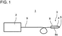
- Figure 1 shows a schematic illustration of an embodiment of a laser surgery apparatus 1 for contact laser surgery according to the invention.
- the laser surgery apparatus 1 comprises a picosecond infrared laser (PIRL) source 2 that is configured to generate pulsed IR laser light of a wavelength falling within a range from 1 ⁇ m to 20 ⁇ m, of a pulse duration falling within a range from 100 fs to 10ns, and of a repetition rate falling within a range from 1 Hz to 1 MHz.
- PIRL picosecond infrared laser
- the laser surgery apparatus 1 further comprises a contact laser scalpel 3 for contact laser surgery that comprises an optical fiber 4 of IR laser radiation transmissive material which terminates at an optical fiber tip 5.
- the fiber tip 5 comprises an exposed core region that is tapered and has a form of a mechanical blade shape (cf. figures 2A to 3F ) and is disposed at a distal end of the scalpel 3 for contacting a tissue to be cut.
- the shaped fiber tip 5 extends forwardly of the handpiece 8 to define a surgical cutting surface.
- the contact laser scalpel 3 is a hand-held portable scalpel and comprises a handpiece or hand support 8, which the surgeon holds during surgery and with which the contact laser scalpel can be moved or used by hand.
- the shape of the hand support can be of conventional design.
- the optical fiber 4 is fastened to the handpiece 8 by providing a hole or passage 8a through the handpiece 8 along the longitudinal scalpel axis through which an extended portion of fiber 4 is passed (which is schematically illustrated in figure 1 by the dashed line). This hole is of appropriate diameter to snugly receive fiber 4 therein.
- the fiber 4 is coupled to light transmitting means 9, e.g. another optical fiber, connecting the PIRL source 2 to the optical fiber 4 of the scalpel 3 for conveying laser radiation from said laser source 2 to the fiber tip 5.
- the optical fiber 4 can be a multi-mode or a single-mode fiber comprising a core of relatively high refractive index, which is surrounded by a cladding of relatively low refractive index. At the portion of the fiber tip 5, the cladding is removed and/or not present.
- the fiber core is made of an IR laser radiation transmissive material, such as Al 2 O 3 , Y 3 Al 5 O 15 , GeO 2 , TeO 2 , ZrF 4 , InF 3 , AlF 3 , endcapped PCF or endcapped hollow core fibers, or other infrared waveguiding fibers.
- the present extended fiber scalpel provides for the transmission of the laser energy from the laser source 2 to the point of operative tissue contact at the scalpel tip end, i.e. the contact surface 6 of fiber tip 5, along a single continuous fiber path without the fiber-to-scalpel interface often used in other contact laser instruments.
- Figure 2A shows an enlarged frontal view of the fiber tip 5 to schematically illustrate the elements of the fiber tip 5.
- Figure 2B shows a corresponding side view and figure 2C a corresponding perspective view of the fiber tip 5.
- the fiber tip 5 is tapered and disposed at a distal end of the scalpel 3 for contacting a tissue to be cut.
- the tip comprises an uncoated contact surface 6 for transmitting and emitting laser radiation and a coated surface 7 that is at least partially reflective to laser radiation and provided such that laser radiation guided by said optical fiber 4 to said fiber tip 5 will be reflected by said guiding surface and emitted through said uncoated contact surface 6.
- a metallic coating is used.
- a stacked oxide coating or a dielectric coating for the infrared region may be used.
- the uncoated surface 6 has a diameter of less than 100 ⁇ m, preferably a diameter of less than 10 ⁇ m.
- the fiber tip 5 shown in these figures has a wedge shape. However, it is emphasized that a wedge-shaped fiber tip is just one example of carrying out the invention, and the invention is not limited to this geometry.
- surgeons When operating with laser surgery contact probes, surgeons use a variety of tip shapes, e.g. depending on the type of incision required, or special shapes for tissue removal and undercut. It will therefore be understood that other tip configurations corresponding to the conventional blade shapes of a mechanical scalpel, such as conical, chisel-shaped etc., may be used alternatively and are illustrated in figures 3A to 3F .
- the uncoated contact surface 6 of the fiber tip is arranged at the location of the cutting section or cutting edge of the corresponding blade shape of the mechanical scalpel.
- the fiber tip shown in figures 2A to 2C corresponds to the fiber tip 5c shown in figure 3C .
- the fiber tip 5c has a planar rectangular uncoated end surface 6c at the distal end of the scalpel 3 forming the uncoated contact surface and coated slant surfaces 7c formed at an angle with respect to the end surface 6c and converging in a direction of the end surface 6c.
- the shaped fiber tip 5c enables to deposit the laser energy at the uncoated end of the fiber tip with a width of tens of micrometers at the interface to the tissue.
- the coating of the fiber tip 5c reflects the light guided in the fiber core 4 to the rectangular area 6c of the fiber tip.
- the fiber tip 5a of figure 3A is conically tapered with a truncated tip, wherein the uncoated circular contact surface 6a is located at the truncated tip and the surface of the cone is coated with a reflective coating.
- the fiber tip 5b shown in figure 3B has a chisel shape.
- the fiber tip 5b comprises a second optical fiber 4b terminating at a second optical fiber tip 5b.
- the second optical fiber tip 5b is arranged in parallel and adjacent to the first fiber tip.
- the two fiber tips 5b are conical-shaped, the conical surface of each fiber tip being coated except for a line segment 6b joining the apex to the perimeter of the large diameter end portion of the conical surface.
- the uncoated line segments 6b of the two fiber tips are arranged facing each other and form a V-shaped uncoated contact area serving as emitting surface for the pulsed laser radiation and also as mechanical cutting edge.
- the fiber tips 5d und 5e shown in figure 3D und 3E have the known shapes of a conventional mechanical side cutting blade.
- the side surface that corresponds to the location of the cutting side surface of the conventional mechanical side cutting blade are the uncoated contact surfaces 6d and 6e resp., the remaining surfaces 7d, 7e are coated with a reflective coating.
- the fiber tip 5f shown in figure 3f has a hook shape wherein the uncoated contact surface 6f of the tip is located at a distal end the tip.
- the remaining surface 7f of the tip is coated with a reflective coating.
- shaped fiber tips 5, 5a to 5f as shown in figures 2A to 2C and 3A to 3F such as laser shaping of the end face of the fiber 4.
- the shaped fiber tips are machined or sculpted on the fiber end using the material of the fiber itself.
- the end face can be polished.
- No additional glass material is added in the process.
- the process can be either mechanical or thermal in nature, the latter being primarily but not limited to laser machining/ laser lensing.
- Figure 4 shows a flow diagram of steps according to a method using the laser surgery apparatus 1 as described above.
- the uncoated portion 6 of the contact tip 5 is applied directly to the tissue to be cut.
- the shaped optical fiber 5 serves both as a means to heat the tissue to be cut and as a mechanical cutting edge to make an incision.
- step S1 the handpiece 8 is thus used to position the fiber tip 5 on a tissue to be cut so that the uncoated contact surface 6 contacts the tissue.
- step S2 the contacted tissue is superheated by pulsed IR laser radiation of the laser source PIRL source 2 emitted from the uncoated surface 6 into the tissue, wherein the water in the contacted tissue is heated to a temperature in the range of 50 °C to ⁇ 200 °C and/or to a temperature below a vaporization or boiling point temperature of the contacted tissue in the range from 100 to 1500 °C for tissue varying from soft tissue to bony and calcified structures/teeth and thereby reducing the shear force needed for cutting the tissue.
- step S3 An incision can then be made in step S3 by simultaneously or subsequently cutting the heated tissue in the region below the uncoated surface 6 of the fiber tip by locally exerting a mechanical shearing force with the fiber tip 5.
- step S2 the virtues of a PIRL source are used to just heat the water in tissues to the boiling point (4x less than typical). This alone is a dramatic improvement in efficiency and reduces laser requirements to near laser pointer output power levels.
- the lattice is no longer bound. It is superheated and any perturbation will lead to lattice disruption and cutting.
- the elasticity of the tissue at this point collapses to near zero so that the force normally needed to cut tissue locally in this region also collapses to near zero or to an at least dramatically reduced force.
- the key feature at this point is that the tissue no longer needs to experience sufficient shear force to tear, the actual mechanism of cutting with a scalpel.
- the present invention locally reduces all the required shearing motion to cut to the region of the hybrid laser scalpel contact region which is less than 10 microns or the dimensions of a single cell.
- the tissue is locally heated in a range of 50 to 100 °C to weaken the hydrogen bonds in the water within the tissue and colligative forces of the connective tissue to reduce the mesh tension to cut with the blade-like fiber tip shape.
- This reduced temperature is well below the combustion point of the tissue in fully oxygenated air, however, it is high enough to lead to local coagulation of the tissue.
- these locally heated proteins and constituent biopolymer matrix are not removed during the cutting process, but remain as a heated biopolymer to help stop bleeding through coagulation.
- the present invention also avoids the disadvantages of laser surgery systems using a continuous wave (CW) laser source which heat the tissue on very long timescales that do not change the tissue's mechanical properties, and there is excessive heat transfer to the surrounding tissue that leads to cell damage and associated scar tissue.
- CW continuous wave
- the same effect can be realized using electric current to heat the blade through resistive heating.
- the present invention explicitly uses the impulsive heating of water with an ultrashort IR pulse to reduce the shear force to cut the tissue to zero or almost zero locally under the applied tip. The tissue disruption in this region localizes the heat.
- the best analogy is to consider cutting asphalt with a jack hammer as opposed to trying to melt the asphalt. If asphalt were heated locally as fast as the jack hammer motion (in this case provided by the near explosive thermal expansion), there would be no crumbling of the asphalt and the cut would be defined by the dimension of the jack hammer bit - in the present case the fiber edge.
- the surgical laser scalpel with a tapered and metallic coated fiber tip has the advantages of pulsed medical lasers, e.g. smaller damage zone, in comparison to electrocautery and conventional lasers. In addition, it avoids the typical disadvantages of pulsed lasers: Due to the reduced fluence, local coagulation of the tissue is achieved and ionization of tissue is avoided. This invention reduces the required laser fluence substantially, by up to an order of magnitude in comparison to some laser sources currently in use. This feature alone leads to much less tissue damage. It also provides the surgeon with a very intuitive tool for surgery that has all the ease of use of a cold steel tool but with orders of magnitude less tissue damage in order to enable scar free operations.
- a further important advantage of the invention is that laser surgery cuts by ablation and the depth of cutting is limited by scattering as the cut gets deeper.
- the laser must be used in a trepanning mode in which the top tissue region must be widened as the cut is made deeper. This process leads to much slower cutting, much more loss of tissue than needed, and is difficult to control as tissue cutting varies with composition.
- using the laser surgery apparatus of the present invention provides a self-guided shear force that opens up the tissue to allow deeper cutting without scattering losses, and avoids the use of other means of stretching the tissue to permit deeper cutting, as typically done with cold instruments.
- Another advantage of the invention results from the fact that the laser surgery apparatus of the present invention can be used to cut at the phase transition threshold for water. As a consequence, there is no ablation debris to coat the optic.
- the device is in contact with tissue and tissue fluids and as such is self-cleaning without any need for means to protect the optics from ablation debris as required by other laser approaches that normally involve long working distances with aspiration to pick up the laser ablation plume. This represents an important advance of this device - in that it provides all the benefits of the state of the art PIRL scalpel for scar free cutting of tissue but with greatly reduced laser power and associated costs.
- a new hybrid concept is proposed in which a hand-held device 3 is used to both give the surgeon complete freedom and laser coupling of a PIRL source to cut at the lowest possible laser fluence.
- the addition of mechanical forces simultaneously with the ultrafast laser heating of the water in the tissue collapses the shear forces needed to cut the tissue to near zero and enables cutting at the level of single cell without damage to surrounding tissue.
Landscapes
- Health & Medical Sciences (AREA)
- Physics & Mathematics (AREA)
- Engineering & Computer Science (AREA)
- Biomedical Technology (AREA)
- Life Sciences & Earth Sciences (AREA)
- Optics & Photonics (AREA)
- Nuclear Medicine, Radiotherapy & Molecular Imaging (AREA)
- Animal Behavior & Ethology (AREA)
- General Health & Medical Sciences (AREA)
- Public Health (AREA)
- Veterinary Medicine (AREA)
- Surgery (AREA)
- Ophthalmology & Optometry (AREA)
- Heart & Thoracic Surgery (AREA)
- Vascular Medicine (AREA)
- Radiology & Medical Imaging (AREA)
- Pathology (AREA)
- Electromagnetism (AREA)
- Otolaryngology (AREA)
- Medical Informatics (AREA)
- Molecular Biology (AREA)
- Laser Surgery Devices (AREA)
Claims (19)
- Eine Laserchirurgievorrichtung (1) für eine Kontakt!aserchirurgie, umfassend(a) ein Kontaktlaserskalpell (3) für Kontaktlaserchirurgie, wobei das Kontaktlaserskalpell (3) umfasst:eine optische Faser (4) aus Material, das für IR-Laserstrahlung durchlässig ist und die an einer optischen Faserspitze (5), die einen freiliegenden Kernbereich aufweist, endet, undStützmittel zum Halten der Faser und zum Positionieren des Skalpells (3), wobei die Faserspitze (5) sich verjüngt und sich an einem distalen Ende des Skalpells (3) befindet zum Kontaktieren eines zu schneidenden Gewebes und eine unbeschichtete Kontaktfläche (6) zur Übertragung von Laserstrahlung und eine Führungsfläche (7) aufweist, wobei die Führungsfläche (7) zumindest teilweise reflektierend für Laserstrahlung ist und so ausgebildet ist, dass die Laserstrahlung, die durch die optische Faser (4) zu der Faserspitze (5) geleitet wird, zumindest teilweise durch die Führungsfläche reflektiert wird und durch die unbeschichtete Kontaktfläche emittiert wird;(b) eine gepulste Laserquelle (2), die angepasst ist um Pulsdauern im Femtosekunden-, Pikosekunden- und/oder Nanosekunden-Bereich bereitzustellen, und(c) Lichtübertragungsmittel (9), die die Laserquelle (2) mit der optischen Faser (4) des Skalpells (3) verbinden, um Laserstrahlung von der Laserquelle (2) zu der optischen Faser (4) zu befördern, so dass das beförderte Laserlicht an der unbeschichteten Kontaktfläche der Faserspitze emittiert wird.
- Eine Laserchirurgievorrichtung nach Anspruch 1, wobei die Wellenlänge, Pulsdauer und Wiederholungsrate der Laserquelle (2) so eingestellt sind, dass wenn die unbeschichtete Kontaktfläche (6) der Faserspitze (5) ein zu schneidendes Gewebe kontaktiert,(a) eine Fluenz der gepulsten Laserstrahlung unter einer Ablationsschwelle des menschlichen Gewebe liegt, und/oder(b) gepulste IR-Laserstrahlung der gepulsten Laserquelle (2), die von der unbeschichteten Kontaktfläche (6) der Faserspitze emittiert wird, Wasser in dem kontaktierten Gewebe auf eine Temperatur erhitzt, die in dem Bereich von 50°C bis <200°C liegt und/oder biologisches Gewebe bis zu einer Temperatur unter einer Verdampfungstemperatur des Gewebes in dem Bereich von 100 bis 1.500°C erwärmt für Gewebe, das von Weichgewebe bis zu knöchernen und verkalkten Strukturen/Zähnen variieren kann und auf diese Weise die zum Schneiden des Gewebes benötigte Scherkraft verringert, und/oder(c) ein chirurgischer Einschnitt getätigt werden kann durch die Bereitstellung einer lokalen impulsiven Erwärmung des Wassers im kontaktierten Gewebe durch gepulste IR-Laserstrahlung der Laserquelle (2) und durch gleichzeitiges oder nachfolgendes Aufbringen einer Scherkraft unter Verwendung der unbeschichteten Kontaktfläche (6) der Faserspitze (5) als mechanische Schneidkante, um das erwärmte Gewebe lokal zu schneiden.
- Eine Laserchirurgievorrichtung nach Anspruch 1 oder Anspruch 2, wobei die gepulste Laserquelle (2) eine Pikosekunden-Infrarotlaser (PIRL)-Quelle ist.
- Eine Laserchirurgievorrichtung nach Anspruch 3, wobei die PIRL-Quelle konfiguriert ist, gepulstes IR-Laserlicht zu erzeugen(a) einer Wellenlänge, die in den Bereich von 1 µm bis 20 µm fällt,(b) einer Pulsdauer, die in einen Bereich von 100 fs bis 10 ns fällt, und(c) einer Wiederholungsrate, die in einen Bereich von 1 Hz bis 1 MHz fällt.
- Eine Laserchirurgievorrichtung nach Anspruch 3, wobei die PIRL-Laserquelle konfiguriert ist, gepulstes IR-Laserlicht mit 3 µm und/oder 6 µm Wellenlänge zu erzeugen.
- Eine Laserchirurgievorrichtung nach einem der vorhergehenden Ansprüche, wobei(a) das Kontaktlaserskalpell ein handgehaltenes tragbares Skalpell (3) ist und/oder die Stützmittel als ein Handstück (8) ausgebildet sind, mit dem das Kontaktlaserskalpell bewegt werden kann oder von Hand benutzt werden kann; und/oder(b) das Kontaktlaserskalpell ein portables Skalpell ist, das eingerichtet ist, durch einen Chirurgieroboter geführt zu werden.
- Eine Laserchirurgievorrichtung gemäß einem der vorhergehenden Ansprüche, wobei die unbeschichtete Fläche (6) einen Durchmesser von weniger als 100 µm, vorzugsweise einen Durchmesser von weniger als 10 µm aufweist.
- Eine Laserchirurgievorrichtung gemäß einem der vorhergehenden Ansprüche, wobei(a) die Faserspitze eine Klingenform eines mechanischen Skalpells aufweist, und(b) die unbeschichtete Kontaktfläche der Faserspitze an der Stelle des Schneidabschnitts oder Schneidkante der Klingenform angeordnet ist.
- Eine Laserchirurgievorrichtung nach einem der vorhergehenden Ansprüche, wobei die Faserspitze eine Keilform (5c), eine Hakenform (5f), eine konische Form (5a), eine Sichelform (5b), eine Form einer Seitenschneidklinge (5e) oder eine Nadelform aufweist.
- Eine Laserchirurgievorrichtung nach einem der vorhergehenden Ansprüche, wobei die Führungsfläche eine beschichtete Oberfläche (7) ist, die reflektierend für Laserstrahlung ist und so vorgesehen ist, dass die Laserstrahlung, die von der optischen Faser (4) zu der Faserspitze (5) geführt wird, von der beschichteten Oberfläche (7) reflektiert und durch die unbeschichtete Oberfläche (6) emittiert wird.
- Eine Laserchirurgievorrichtung nach Anspruch 10, wobei die beschichtete Oberfläche (7) eine metallische Beschichtung, eine gestapelte Oxidbeschichtung und/oder eine dielektrische Beschichtung für den Infrarotbereich aufweist.
- Eine Laserchirurgievorrichtung nach Anspruch 10 oder 11, wobei die Faserspitze (5c) keilförmig ist, und eine ebene rechteckige unbeschichtete Endfläche (6c) am distalen Ende des Skalpells aufweist, die die unbeschichtete Kontaktfläche ausbildet und eine beschichtete schräge Fläche (7c) aufweist, die in einem Winkel in Bezug auf die Endfläche ausgebildet ist und die in Richtung der Endfläche konvergiert.
- Eine Laserchirurgievorrichtung nach Anspruch 10 oder 11, wobei das Kontaktlaserskalpell ferner eine zweite optische Faser (4b) umfasst, die an einer zweiten optischen Faserspitze (5b) endet, wobei(a) die zweite optische Faserspitze (5b) parallel und benachbart zu der ersten Faserspitze angeordnet ist, und(b) die beiden Faserspitzen (5b) konisch geformt sind, wobei die konische Oberfläche jeder Faserspitze mit Ausnahme eines Liniensegments (6b) beschichtet ist, wobei das Liniensegment (6b) die Kegelspitze mit dem Umfang des Endbereichs mit dem großen Durchmesser der konischen Oberfläche verbindet, und wobei die unbeschichteten Liniensegmente (6b) der beiden Faserspitzen zueinander zugewandt angeordnet sind und einen V-förmigen unbeschichteten Kontaktbereich ausbilden.
- Eine Laserchirurgievorrichtung nach einem der Ansprüche 1 bis 9, wobei die Führungsfläche eine unbeschichtete Oberfläche ist mit einem Verjüngungswinkel, derart, dass zumindest 30% der Laserstrahlung, die durch die optische Faser bis zur Faserspitze geleitet wird, an der Führungsfläche reflektiert wird und nachfolgend durch die unbeschichtete Kontaktfläche emittiert wird.
- Eine Laserchirurgievorrichtung nach Anspruch 14, wobei die optische Faserspitze eine Saphir (Al2O3)-Faser ist und der sich verjüngende Winkel niedriger als 15° oder niedriger als 11° ist.
- Eine Laserchirurgievorrichtung nach einem der vorhergehenden Ansprüche, wobei die optische Faserspitze aus Al2O3, Y3Al5O15, GeO2, TeO2, ZrF4, InF3, AlF3, endverkappten PCF- oder endverkappten Hohlkernfasern oder anderen Infrarotwellenleitfasern bestehen.
- Eine Laserchirurgievorrichtung nach einem der vorhergehenden Ansprüche, wobei ein Durchmesser eines Führungsfaserkerns der optischen Faser im Bereich von 4-1000 µm vor einer Verjüngung oder Strukturierung der Faserspitze liegt.
- Eine Laserchirurgievorrichtung nach einem der Ansprüche 1 bis 16, wobei die optische Faser eine Einmodenfaser ist und der Durchmesser eines Faserkerns im Bereich von 1 bis 100 µm liegt.
- Eine Laserchirurgievorrichtung nach einem der Ansprüche 1 bis 18, ferner umfassend(a) ein Eingabeanschluss zur Auswahl eines zu schneidenden Gewebetyps und(b) eine Laserquellensteuerungseinheit, die zum Steuern einer Wellenlänge, Pulsdauer und/oder einer Wiederholungsrate der erzeugten Laserstrahlung basierend auf dem ausgewählten Gewebetyp ausgebildet ist.
Priority Applications (3)
| Application Number | Priority Date | Filing Date | Title |
|---|---|---|---|
| EP15000757.3A EP3067005B1 (de) | 2015-03-13 | 2015-03-13 | Laserchirurgievorrichtung für kontaktlaserchirurgie |
| US15/557,552 US10799393B2 (en) | 2015-03-13 | 2016-02-19 | Laser surgery apparatus for contact laser surgery |
| PCT/EP2016/000291 WO2016146237A1 (en) | 2015-03-13 | 2016-02-19 | Laser surgery apparatus for contact laser surgery |
Applications Claiming Priority (1)
| Application Number | Priority Date | Filing Date | Title |
|---|---|---|---|
| EP15000757.3A EP3067005B1 (de) | 2015-03-13 | 2015-03-13 | Laserchirurgievorrichtung für kontaktlaserchirurgie |
Publications (2)
| Publication Number | Publication Date |
|---|---|
| EP3067005A1 EP3067005A1 (de) | 2016-09-14 |
| EP3067005B1 true EP3067005B1 (de) | 2017-11-08 |
Family
ID=52686051
Family Applications (1)
| Application Number | Title | Priority Date | Filing Date |
|---|---|---|---|
| EP15000757.3A Active EP3067005B1 (de) | 2015-03-13 | 2015-03-13 | Laserchirurgievorrichtung für kontaktlaserchirurgie |
Country Status (3)
| Country | Link |
|---|---|
| US (1) | US10799393B2 (de) |
| EP (1) | EP3067005B1 (de) |
| WO (1) | WO2016146237A1 (de) |
Cited By (1)
| Publication number | Priority date | Publication date | Assignee | Title |
|---|---|---|---|---|
| EP3308734B1 (de) * | 2016-10-11 | 2022-04-27 | biolitec unternehmensbeteiligungs II AG | Optisches skalpell und chirurgische schneidevorrichtung |
Families Citing this family (4)
| Publication number | Priority date | Publication date | Assignee | Title |
|---|---|---|---|---|
| US10912612B2 (en) * | 2018-01-17 | 2021-02-09 | Gyrus Acmi, Inc. | System and device for treating body tissue |
| US12383757B2 (en) * | 2019-08-27 | 2025-08-12 | Strata Skin Sciences Inc. | Tip section for use in phototherapy |
| US12076080B2 (en) | 2020-06-04 | 2024-09-03 | University Of Iowa Research Foundation | Compact laser scalpel and method for preferential ablation of tumor tissue |
| KR20240076781A (ko) * | 2021-08-27 | 2024-05-30 | 라이트 매터 인터랙션 인크. | 레이저 펄스를 사용하여 조직에 절개를 형성하는 시스템, 장치 및 방법 |
Family Cites Families (11)
| Publication number | Priority date | Publication date | Assignee | Title |
|---|---|---|---|---|
| US4126136A (en) | 1976-02-09 | 1978-11-21 | Research Corporation | Photocoagulating scalpel system |
| GB2139500B (en) * | 1983-05-14 | 1986-07-30 | Hpw Ltd | Surgical laser knives |
| US4672969A (en) * | 1983-10-06 | 1987-06-16 | Sonomo Corporation | Laser healing method |
| US4736743A (en) | 1986-05-12 | 1988-04-12 | Surgical Laser Technology, Inc. | Vaporization contact laser probe |
| US5951543A (en) * | 1997-06-30 | 1999-09-14 | Clinicon Corporation | Delivery system and method for surgical laser |
| WO2001087176A1 (en) * | 2000-05-15 | 2001-11-22 | Clinicon Corporation | Optical surgical system and method |
| WO2003009767A1 (en) * | 2001-07-20 | 2003-02-06 | Element Six B.V. | Cutting tool and method |
| DE10349047B3 (de) * | 2003-10-17 | 2005-02-24 | Kettenbach Gmbh & Co. Kg | Verfahren und Abdrucklöffel zur Herstellung einer Dentalschiene |
| WO2006072183A2 (en) * | 2005-01-10 | 2006-07-13 | Kresimir Franjic | LASER SYSTEM FOR GENERATION OF HIGH-POWER SUB-NANOSECOND PULSES WITH CONTROLLABLE WAVELENGTHS IN 2-15 um REGION |
| US20120135368A1 (en) * | 2007-01-26 | 2012-05-31 | Rizoiu Ioana M | Modified-ouput fiber optic tips |
| DE102009011587A1 (de) | 2009-03-06 | 2010-09-16 | A.R.C. Laser Gmbh | Laserskalpell |
-
2015
- 2015-03-13 EP EP15000757.3A patent/EP3067005B1/de active Active
-
2016
- 2016-02-19 US US15/557,552 patent/US10799393B2/en active Active
- 2016-02-19 WO PCT/EP2016/000291 patent/WO2016146237A1/en not_active Ceased
Non-Patent Citations (1)
| Title |
|---|
| None * |
Cited By (1)
| Publication number | Priority date | Publication date | Assignee | Title |
|---|---|---|---|---|
| EP3308734B1 (de) * | 2016-10-11 | 2022-04-27 | biolitec unternehmensbeteiligungs II AG | Optisches skalpell und chirurgische schneidevorrichtung |
Also Published As
| Publication number | Publication date |
|---|---|
| WO2016146237A1 (en) | 2016-09-22 |
| EP3067005A1 (de) | 2016-09-14 |
| US10799393B2 (en) | 2020-10-13 |
| US20180055690A1 (en) | 2018-03-01 |
Similar Documents
| Publication | Publication Date | Title |
|---|---|---|
| US10799393B2 (en) | Laser surgery apparatus for contact laser surgery | |
| US6179830B1 (en) | Laser probe | |
| US6395000B1 (en) | High repetition rate erbium: YAG laser for tissue ablation | |
| JP3148216B2 (ja) | レーザ光照射による治療装置 | |
| US5151098A (en) | Apparatus for controlled tissue ablation | |
| US5498260A (en) | Internal reflectance angle firing fiber optic laser delivery device and method of use | |
| US6383179B1 (en) | Diode laser scalpel | |
| EP3223739B1 (de) | Zahnärztliches laserbehandlungssystem | |
| CA2117765A1 (en) | Apparatus and method for performing eye surgery | |
| EP0397777A1 (de) | Verfahren und vorichtung für laserchirurgie | |
| EP0335714A2 (de) | Gerät zur Gewebeentfernung mittels Lasertechnologie | |
| US6673065B1 (en) | Slender tip laser scalpel | |
| WO1991002562A1 (en) | Integral end structure for medical laser waveguide | |
| Bonner et al. | Quantification of tissue effects due to a pulsed Er: YAG laser at 2.9 gm with beam delivery in a wet field via zirconium fluoride fibers | |
| JP6553021B2 (ja) | 組織除去装置 | |
| US11291504B1 (en) | Method of incising and ablating living tissues and surgical laser devices | |
| US20220265296A1 (en) | Hybrid laser cutter | |
| Pryshlak et al. | Advancements in sapphire optical fibers for the delivery of erbium laser energy and IR sensor applications | |
| CN1157161C (zh) | 用于手术工具的切割刀片 | |
| Giesen et al. | Efficient and tissue-saving bone ablation with a pulsed 3 µm laser source | |
| RU2038106C1 (ru) | Лазерное излучающее устройство для медицинской обработки | |
| Gudra et al. | Some problems of ultrasonic and laser cutting of biological structures | |
| Mishra et al. | Toward high-speed ultrafast laser surgery: optimizing bone ablation performance in miniaturized systems | |
| Steiner et al. | Comparison of core fibers and contact probes for laser surgery | |
| GRANT | Study of the interaction of silica-based Nd: YAG laser optical fibers with tissue(Ph. D. Thesis) |
Legal Events
| Date | Code | Title | Description |
|---|---|---|---|
| PUAI | Public reference made under article 153(3) epc to a published international application that has entered the european phase |
Free format text: ORIGINAL CODE: 0009012 |
|
| AK | Designated contracting states |
Kind code of ref document: A1 Designated state(s): AL AT BE BG CH CY CZ DE DK EE ES FI FR GB GR HR HU IE IS IT LI LT LU LV MC MK MT NL NO PL PT RO RS SE SI SK SM TR |
|
| AX | Request for extension of the european patent |
Extension state: BA ME |
|
| STAA | Information on the status of an ep patent application or granted ep patent |
Free format text: STATUS: REQUEST FOR EXAMINATION WAS MADE |
|
| 17P | Request for examination filed |
Effective date: 20170209 |
|
| RBV | Designated contracting states (corrected) |
Designated state(s): AL AT BE BG CH CY CZ DE DK EE ES FI FR GB GR HR HU IE IS IT LI LT LU LV MC MK MT NL NO PL PT RO RS SE SI SK SM TR |
|
| GRAP | Despatch of communication of intention to grant a patent |
Free format text: ORIGINAL CODE: EPIDOSNIGR1 |
|
| STAA | Information on the status of an ep patent application or granted ep patent |
Free format text: STATUS: GRANT OF PATENT IS INTENDED |
|
| INTG | Intention to grant announced |
Effective date: 20170529 |
|
| RIN1 | Information on inventor provided before grant (corrected) |
Inventor name: HANSEN, NILS-OWE Inventor name: MAIER, STEPHANIE Inventor name: MILLER, R.J. DWAYNE Inventor name: KRUBER, SEBASTIAN |
|
| GRAS | Grant fee paid |
Free format text: ORIGINAL CODE: EPIDOSNIGR3 |
|
| GRAA | (expected) grant |
Free format text: ORIGINAL CODE: 0009210 |
|
| STAA | Information on the status of an ep patent application or granted ep patent |
Free format text: STATUS: THE PATENT HAS BEEN GRANTED |
|
| AK | Designated contracting states |
Kind code of ref document: B1 Designated state(s): AL AT BE BG CH CY CZ DE DK EE ES FI FR GB GR HR HU IE IS IT LI LT LU LV MC MK MT NL NO PL PT RO RS SE SI SK SM TR |
|
| REG | Reference to a national code |
Ref country code: GB Ref legal event code: FG4D |
|
| REG | Reference to a national code |
Ref country code: CH Ref legal event code: EP Ref country code: AT Ref legal event code: REF Ref document number: 943419 Country of ref document: AT Kind code of ref document: T Effective date: 20171115 |
|
| REG | Reference to a national code |
Ref country code: IE Ref legal event code: FG4D |
|
| REG | Reference to a national code |
Ref country code: DE Ref legal event code: R096 Ref document number: 602015005760 Country of ref document: DE |
|
| REG | Reference to a national code |
Ref country code: NL Ref legal event code: FP |
|
| REG | Reference to a national code |
Ref country code: CH Ref legal event code: NV Representative=s name: KASCHE AND PARTNER AG, CH |
|
| REG | Reference to a national code |
Ref country code: LT Ref legal event code: MG4D Ref country code: FR Ref legal event code: PLFP Year of fee payment: 4 |
|
| REG | Reference to a national code |
Ref country code: AT Ref legal event code: MK05 Ref document number: 943419 Country of ref document: AT Kind code of ref document: T Effective date: 20171108 |
|
| PG25 | Lapsed in a contracting state [announced via postgrant information from national office to epo] |
Ref country code: LT Free format text: LAPSE BECAUSE OF FAILURE TO SUBMIT A TRANSLATION OF THE DESCRIPTION OR TO PAY THE FEE WITHIN THE PRESCRIBED TIME-LIMIT Effective date: 20171108 Ref country code: NO Free format text: LAPSE BECAUSE OF FAILURE TO SUBMIT A TRANSLATION OF THE DESCRIPTION OR TO PAY THE FEE WITHIN THE PRESCRIBED TIME-LIMIT Effective date: 20180208 Ref country code: ES Free format text: LAPSE BECAUSE OF FAILURE TO SUBMIT A TRANSLATION OF THE DESCRIPTION OR TO PAY THE FEE WITHIN THE PRESCRIBED TIME-LIMIT Effective date: 20171108 Ref country code: SE Free format text: LAPSE BECAUSE OF FAILURE TO SUBMIT A TRANSLATION OF THE DESCRIPTION OR TO PAY THE FEE WITHIN THE PRESCRIBED TIME-LIMIT Effective date: 20171108 Ref country code: FI Free format text: LAPSE BECAUSE OF FAILURE TO SUBMIT A TRANSLATION OF THE DESCRIPTION OR TO PAY THE FEE WITHIN THE PRESCRIBED TIME-LIMIT Effective date: 20171108 |
|
| PG25 | Lapsed in a contracting state [announced via postgrant information from national office to epo] |
Ref country code: AT Free format text: LAPSE BECAUSE OF FAILURE TO SUBMIT A TRANSLATION OF THE DESCRIPTION OR TO PAY THE FEE WITHIN THE PRESCRIBED TIME-LIMIT Effective date: 20171108 Ref country code: IS Free format text: LAPSE BECAUSE OF FAILURE TO SUBMIT A TRANSLATION OF THE DESCRIPTION OR TO PAY THE FEE WITHIN THE PRESCRIBED TIME-LIMIT Effective date: 20180308 Ref country code: LV Free format text: LAPSE BECAUSE OF FAILURE TO SUBMIT A TRANSLATION OF THE DESCRIPTION OR TO PAY THE FEE WITHIN THE PRESCRIBED TIME-LIMIT Effective date: 20171108 Ref country code: HR Free format text: LAPSE BECAUSE OF FAILURE TO SUBMIT A TRANSLATION OF THE DESCRIPTION OR TO PAY THE FEE WITHIN THE PRESCRIBED TIME-LIMIT Effective date: 20171108 Ref country code: RS Free format text: LAPSE BECAUSE OF FAILURE TO SUBMIT A TRANSLATION OF THE DESCRIPTION OR TO PAY THE FEE WITHIN THE PRESCRIBED TIME-LIMIT Effective date: 20171108 Ref country code: GR Free format text: LAPSE BECAUSE OF FAILURE TO SUBMIT A TRANSLATION OF THE DESCRIPTION OR TO PAY THE FEE WITHIN THE PRESCRIBED TIME-LIMIT Effective date: 20180209 Ref country code: BG Free format text: LAPSE BECAUSE OF FAILURE TO SUBMIT A TRANSLATION OF THE DESCRIPTION OR TO PAY THE FEE WITHIN THE PRESCRIBED TIME-LIMIT Effective date: 20180208 |
|
| PG25 | Lapsed in a contracting state [announced via postgrant information from national office to epo] |
Ref country code: SK Free format text: LAPSE BECAUSE OF FAILURE TO SUBMIT A TRANSLATION OF THE DESCRIPTION OR TO PAY THE FEE WITHIN THE PRESCRIBED TIME-LIMIT Effective date: 20171108 Ref country code: CZ Free format text: LAPSE BECAUSE OF FAILURE TO SUBMIT A TRANSLATION OF THE DESCRIPTION OR TO PAY THE FEE WITHIN THE PRESCRIBED TIME-LIMIT Effective date: 20171108 Ref country code: DK Free format text: LAPSE BECAUSE OF FAILURE TO SUBMIT A TRANSLATION OF THE DESCRIPTION OR TO PAY THE FEE WITHIN THE PRESCRIBED TIME-LIMIT Effective date: 20171108 Ref country code: CY Free format text: LAPSE BECAUSE OF FAILURE TO SUBMIT A TRANSLATION OF THE DESCRIPTION OR TO PAY THE FEE WITHIN THE PRESCRIBED TIME-LIMIT Effective date: 20171108 Ref country code: EE Free format text: LAPSE BECAUSE OF FAILURE TO SUBMIT A TRANSLATION OF THE DESCRIPTION OR TO PAY THE FEE WITHIN THE PRESCRIBED TIME-LIMIT Effective date: 20171108 |
|
| REG | Reference to a national code |
Ref country code: DE Ref legal event code: R097 Ref document number: 602015005760 Country of ref document: DE |
|
| PG25 | Lapsed in a contracting state [announced via postgrant information from national office to epo] |
Ref country code: RO Free format text: LAPSE BECAUSE OF FAILURE TO SUBMIT A TRANSLATION OF THE DESCRIPTION OR TO PAY THE FEE WITHIN THE PRESCRIBED TIME-LIMIT Effective date: 20171108 Ref country code: PL Free format text: LAPSE BECAUSE OF FAILURE TO SUBMIT A TRANSLATION OF THE DESCRIPTION OR TO PAY THE FEE WITHIN THE PRESCRIBED TIME-LIMIT Effective date: 20171108 Ref country code: IT Free format text: LAPSE BECAUSE OF FAILURE TO SUBMIT A TRANSLATION OF THE DESCRIPTION OR TO PAY THE FEE WITHIN THE PRESCRIBED TIME-LIMIT Effective date: 20171108 Ref country code: SM Free format text: LAPSE BECAUSE OF FAILURE TO SUBMIT A TRANSLATION OF THE DESCRIPTION OR TO PAY THE FEE WITHIN THE PRESCRIBED TIME-LIMIT Effective date: 20171108 |
|
| PLBE | No opposition filed within time limit |
Free format text: ORIGINAL CODE: 0009261 |
|
| STAA | Information on the status of an ep patent application or granted ep patent |
Free format text: STATUS: NO OPPOSITION FILED WITHIN TIME LIMIT |
|
| 26N | No opposition filed |
Effective date: 20180809 |
|
| PG25 | Lapsed in a contracting state [announced via postgrant information from national office to epo] |
Ref country code: MC Free format text: LAPSE BECAUSE OF FAILURE TO SUBMIT A TRANSLATION OF THE DESCRIPTION OR TO PAY THE FEE WITHIN THE PRESCRIBED TIME-LIMIT Effective date: 20171108 Ref country code: SI Free format text: LAPSE BECAUSE OF FAILURE TO SUBMIT A TRANSLATION OF THE DESCRIPTION OR TO PAY THE FEE WITHIN THE PRESCRIBED TIME-LIMIT Effective date: 20171108 |
|
| REG | Reference to a national code |
Ref country code: BE Ref legal event code: MM Effective date: 20180331 |
|
| REG | Reference to a national code |
Ref country code: IE Ref legal event code: MM4A |
|
| PG25 | Lapsed in a contracting state [announced via postgrant information from national office to epo] |
Ref country code: LU Free format text: LAPSE BECAUSE OF NON-PAYMENT OF DUE FEES Effective date: 20180313 |
|
| PG25 | Lapsed in a contracting state [announced via postgrant information from national office to epo] |
Ref country code: IE Free format text: LAPSE BECAUSE OF NON-PAYMENT OF DUE FEES Effective date: 20180313 |
|
| PG25 | Lapsed in a contracting state [announced via postgrant information from national office to epo] |
Ref country code: BE Free format text: LAPSE BECAUSE OF NON-PAYMENT OF DUE FEES Effective date: 20180331 |
|
| PG25 | Lapsed in a contracting state [announced via postgrant information from national office to epo] |
Ref country code: MT Free format text: LAPSE BECAUSE OF NON-PAYMENT OF DUE FEES Effective date: 20180313 |
|
| PG25 | Lapsed in a contracting state [announced via postgrant information from national office to epo] |
Ref country code: TR Free format text: LAPSE BECAUSE OF FAILURE TO SUBMIT A TRANSLATION OF THE DESCRIPTION OR TO PAY THE FEE WITHIN THE PRESCRIBED TIME-LIMIT Effective date: 20171108 |
|
| PG25 | Lapsed in a contracting state [announced via postgrant information from national office to epo] |
Ref country code: PT Free format text: LAPSE BECAUSE OF FAILURE TO SUBMIT A TRANSLATION OF THE DESCRIPTION OR TO PAY THE FEE WITHIN THE PRESCRIBED TIME-LIMIT Effective date: 20171108 |
|
| PG25 | Lapsed in a contracting state [announced via postgrant information from national office to epo] |
Ref country code: MK Free format text: LAPSE BECAUSE OF NON-PAYMENT OF DUE FEES Effective date: 20171108 Ref country code: HU Free format text: LAPSE BECAUSE OF FAILURE TO SUBMIT A TRANSLATION OF THE DESCRIPTION OR TO PAY THE FEE WITHIN THE PRESCRIBED TIME-LIMIT; INVALID AB INITIO Effective date: 20150313 |
|
| PG25 | Lapsed in a contracting state [announced via postgrant information from national office to epo] |
Ref country code: AL Free format text: LAPSE BECAUSE OF FAILURE TO SUBMIT A TRANSLATION OF THE DESCRIPTION OR TO PAY THE FEE WITHIN THE PRESCRIBED TIME-LIMIT Effective date: 20171108 |
|
| PGFP | Annual fee paid to national office [announced via postgrant information from national office to epo] |
Ref country code: NL Payment date: 20250324 Year of fee payment: 11 |
|
| PGFP | Annual fee paid to national office [announced via postgrant information from national office to epo] |
Ref country code: CH Payment date: 20250401 Year of fee payment: 11 |
|
| REG | Reference to a national code |
Ref country code: CH Ref legal event code: R17 Free format text: ST27 STATUS EVENT CODE: U-0-0-R10-R17 (AS PROVIDED BY THE NATIONAL OFFICE) Effective date: 20251212 |
|
| PGFP | Annual fee paid to national office [announced via postgrant information from national office to epo] |
Ref country code: GB Payment date: 20260324 Year of fee payment: 12 |
|
| PGFP | Annual fee paid to national office [announced via postgrant information from national office to epo] |
Ref country code: DE Payment date: 20260325 Year of fee payment: 12 |
|
| PGFP | Annual fee paid to national office [announced via postgrant information from national office to epo] |
Ref country code: FR Payment date: 20260324 Year of fee payment: 12 |