EP3067018A1 - Verbesserungen an oder im zusammenhang mit prothetischen beinen - Google Patents
Verbesserungen an oder im zusammenhang mit prothetischen beinen Download PDFInfo
- Publication number
- EP3067018A1 EP3067018A1 EP16020083.8A EP16020083A EP3067018A1 EP 3067018 A1 EP3067018 A1 EP 3067018A1 EP 16020083 A EP16020083 A EP 16020083A EP 3067018 A1 EP3067018 A1 EP 3067018A1
- Authority
- EP
- European Patent Office
- Prior art keywords
- knee
- damper
- thigh
- prosthetic
- joint
- Prior art date
- Legal status (The legal status is an assumption and is not a legal conclusion. Google has not performed a legal analysis and makes no representation as to the accuracy of the status listed.)
- Granted
Links
Images


Classifications
-
- A—HUMAN NECESSITIES
- A61—MEDICAL OR VETERINARY SCIENCE; HYGIENE
- A61F—FILTERS IMPLANTABLE INTO BLOOD VESSELS; PROSTHESES; DEVICES PROVIDING PATENCY TO, OR PREVENTING COLLAPSING OF, TUBULAR STRUCTURES OF THE BODY, e.g. STENTS; ORTHOPAEDIC, NURSING OR CONTRACEPTIVE DEVICES; FOMENTATION; TREATMENT OR PROTECTION OF EYES OR EARS; BANDAGES, DRESSINGS OR ABSORBENT PADS; FIRST-AID KITS
- A61F2/00—Filters implantable into blood vessels; Prostheses, i.e. artificial substitutes or replacements for parts of the body; Appliances for connecting them with the body; Devices providing patency to, or preventing collapsing of, tubular structures of the body, e.g. stents
- A61F2/50—Prostheses not implantable in the body
- A61F2/60—Artificial legs or feet or parts thereof
- A61F2/64—Knee joints
- A61F2/642—Polycentric joints, without longitudinal rotation
-
- A—HUMAN NECESSITIES
- A61—MEDICAL OR VETERINARY SCIENCE; HYGIENE
- A61F—FILTERS IMPLANTABLE INTO BLOOD VESSELS; PROSTHESES; DEVICES PROVIDING PATENCY TO, OR PREVENTING COLLAPSING OF, TUBULAR STRUCTURES OF THE BODY, e.g. STENTS; ORTHOPAEDIC, NURSING OR CONTRACEPTIVE DEVICES; FOMENTATION; TREATMENT OR PROTECTION OF EYES OR EARS; BANDAGES, DRESSINGS OR ABSORBENT PADS; FIRST-AID KITS
- A61F2/00—Filters implantable into blood vessels; Prostheses, i.e. artificial substitutes or replacements for parts of the body; Appliances for connecting them with the body; Devices providing patency to, or preventing collapsing of, tubular structures of the body, e.g. stents
- A61F2/50—Prostheses not implantable in the body
- A61F2/60—Artificial legs or feet or parts thereof
-
- A—HUMAN NECESSITIES
- A61—MEDICAL OR VETERINARY SCIENCE; HYGIENE
- A61F—FILTERS IMPLANTABLE INTO BLOOD VESSELS; PROSTHESES; DEVICES PROVIDING PATENCY TO, OR PREVENTING COLLAPSING OF, TUBULAR STRUCTURES OF THE BODY, e.g. STENTS; ORTHOPAEDIC, NURSING OR CONTRACEPTIVE DEVICES; FOMENTATION; TREATMENT OR PROTECTION OF EYES OR EARS; BANDAGES, DRESSINGS OR ABSORBENT PADS; FIRST-AID KITS
- A61F2/00—Filters implantable into blood vessels; Prostheses, i.e. artificial substitutes or replacements for parts of the body; Appliances for connecting them with the body; Devices providing patency to, or preventing collapsing of, tubular structures of the body, e.g. stents
- A61F2/50—Prostheses not implantable in the body
- A61F2/68—Operating or control means
- A61F2/70—Operating or control means electrical
-
- A—HUMAN NECESSITIES
- A61—MEDICAL OR VETERINARY SCIENCE; HYGIENE
- A61F—FILTERS IMPLANTABLE INTO BLOOD VESSELS; PROSTHESES; DEVICES PROVIDING PATENCY TO, OR PREVENTING COLLAPSING OF, TUBULAR STRUCTURES OF THE BODY, e.g. STENTS; ORTHOPAEDIC, NURSING OR CONTRACEPTIVE DEVICES; FOMENTATION; TREATMENT OR PROTECTION OF EYES OR EARS; BANDAGES, DRESSINGS OR ABSORBENT PADS; FIRST-AID KITS
- A61F2/00—Filters implantable into blood vessels; Prostheses, i.e. artificial substitutes or replacements for parts of the body; Appliances for connecting them with the body; Devices providing patency to, or preventing collapsing of, tubular structures of the body, e.g. stents
- A61F2/50—Prostheses not implantable in the body
- A61F2/68—Operating or control means
- A61F2/74—Operating or control means fluid, i.e. hydraulic or pneumatic
- A61F2/748—Valve systems
-
- A—HUMAN NECESSITIES
- A61—MEDICAL OR VETERINARY SCIENCE; HYGIENE
- A61F—FILTERS IMPLANTABLE INTO BLOOD VESSELS; PROSTHESES; DEVICES PROVIDING PATENCY TO, OR PREVENTING COLLAPSING OF, TUBULAR STRUCTURES OF THE BODY, e.g. STENTS; ORTHOPAEDIC, NURSING OR CONTRACEPTIVE DEVICES; FOMENTATION; TREATMENT OR PROTECTION OF EYES OR EARS; BANDAGES, DRESSINGS OR ABSORBENT PADS; FIRST-AID KITS
- A61F2/00—Filters implantable into blood vessels; Prostheses, i.e. artificial substitutes or replacements for parts of the body; Appliances for connecting them with the body; Devices providing patency to, or preventing collapsing of, tubular structures of the body, e.g. stents
- A61F2/50—Prostheses not implantable in the body
- A61F2002/5003—Prostheses not implantable in the body having damping means, e.g. shock absorbers
- A61F2002/5006—Dampers, e.g. hydraulic damper
-
- A—HUMAN NECESSITIES
- A61—MEDICAL OR VETERINARY SCIENCE; HYGIENE
- A61F—FILTERS IMPLANTABLE INTO BLOOD VESSELS; PROSTHESES; DEVICES PROVIDING PATENCY TO, OR PREVENTING COLLAPSING OF, TUBULAR STRUCTURES OF THE BODY, e.g. STENTS; ORTHOPAEDIC, NURSING OR CONTRACEPTIVE DEVICES; FOMENTATION; TREATMENT OR PROTECTION OF EYES OR EARS; BANDAGES, DRESSINGS OR ABSORBENT PADS; FIRST-AID KITS
- A61F2/00—Filters implantable into blood vessels; Prostheses, i.e. artificial substitutes or replacements for parts of the body; Appliances for connecting them with the body; Devices providing patency to, or preventing collapsing of, tubular structures of the body, e.g. stents
- A61F2/50—Prostheses not implantable in the body
- A61F2/68—Operating or control means
- A61F2/70—Operating or control means electrical
- A61F2002/704—Operating or control means electrical computer-controlled, e.g. robotic control
-
- A—HUMAN NECESSITIES
- A61—MEDICAL OR VETERINARY SCIENCE; HYGIENE
- A61F—FILTERS IMPLANTABLE INTO BLOOD VESSELS; PROSTHESES; DEVICES PROVIDING PATENCY TO, OR PREVENTING COLLAPSING OF, TUBULAR STRUCTURES OF THE BODY, e.g. STENTS; ORTHOPAEDIC, NURSING OR CONTRACEPTIVE DEVICES; FOMENTATION; TREATMENT OR PROTECTION OF EYES OR EARS; BANDAGES, DRESSINGS OR ABSORBENT PADS; FIRST-AID KITS
- A61F2/00—Filters implantable into blood vessels; Prostheses, i.e. artificial substitutes or replacements for parts of the body; Appliances for connecting them with the body; Devices providing patency to, or preventing collapsing of, tubular structures of the body, e.g. stents
- A61F2/50—Prostheses not implantable in the body
- A61F2/76—Means for assembling, fitting or testing prostheses, e.g. for measuring or balancing, e.g. alignment means
- A61F2002/7615—Measuring means
- A61F2002/7635—Measuring means for measuring force, pressure or mechanical tension
Definitions
- the present invention relates generally to prosthetic legs and, in particular to modular knee joints for prosthetic legs.
- the present invention relates to a prosthetic leg for those having had a trans-femoral amputation, namely those having an above the knee stump, and particularly to a prosthetic leg for trans-femoral amputees for whom 50% or more of their femur has been amputated.
- the present invention also lends itself to prosthetic modularity.
- the prosthesis comprises a mechanical apparatus performing the duty of the joint that is substantially distal to the hip can induce a lack of balance.
- patients having a substantial reduction in femoral length will suffer greatly since the prosthetic attachment, typically having a hollow region, a socket, in which to insert the remaining length of thigh, the stump.
- the stump will bear upon the distal aspect of the femur and the femoral lever action will be reduced, in correspondence with the reduction in length.
- the pressures can become unbearably high, often resulting in an occurrence of friction burns arising through sliding contact with the prosthesis stump.
- the length to width ratio of the stump can come close to 1:1 as opposed to a 2:1 or 3:1.
- the centre of mass of a state of the art knee mechanism in a lower limb prosthesis is distal to the knee centre, inclusive of operable linear dampers, and rotary dampers, which allows for a universal application of the prosthetic joint, indeed, any aspect of such a joint proximal to the knee centre is kept as short as possible to support a wide as possible commercial and clinical application independent of femoral stump length.
- a short femoral stump residual femur length, say less than 30%
- prosthetic knee mechanisms There are five distinct categories of prosthetic knee mechanisms.
- the primary design as in the most common type - comprises a polycentric mechanism wherein the virtual centre of rotation is often placed well above the anatomical knee axis - the mechanical apparatus, and its centre of mass (approx. 850 gr, 11 ⁇ 2 lb), is distal to the anatomical knee centre.
- Another prosthetic mechanism is the hydraulic swing'n'stance SNS mechanism developed in the late 1960's by Hans Mauch. This design operates in a stance phase of operation in a default mode. This, again, is enabled at a point distal to the anatomical joint centre.
- a further prosthetic type comprises a weight activated type of knee joint such as described in GB2464620 (Boender ).
- a fourth type of prosthesis is exemplified by a number of relatively expensive, external battery powered, electromechanical knee joints having sensors and dampers operating under software control for control of the same joint function, albeit with a relatively high mass (approx 1.4 kg, 3 lb), distal to the knee centre.
- a fifth type of prosthesis is the fluidic controlled knee joint, wherein by means of fluid flow and mechanical linkages, appropriate negative feedback to the control of movement can be realised, which suffers the same penalty of a relatively high mass, distal to the knee centre. It will be readily understood that the more distal and the larger the mass of the knee joint becomes, the effects of unwanted reactive pressures which act on the distal end of a short amputation stump are exacerbated, even at low ambulatory speeds.
- prostheses manufacturers have adopted certain interoperability standards whereby a modular knee joint from one manufacturer can be replaced with a unit form another manufacturer, meaning that the knee joint is a dismountable and exchangeable part of a whole leg prosthesis.
- each knee joint prosthesis cooperates with other parts of the prosthesis such as the foot in mid-swing, and operable to lower the mass of the user's body down a stair, it is a distinct modular device with a proximal end and a distal end which are the boundaries of the space envelope of the knee joint per se.
- a modular joint as an individual product, has a centre of mass and the weight of a modular joint is typically declared in the sales literature and is provided with distributed product.
- Typical prior art modular knee joints have their centre of mass distal to the knee centre (or knee axis) about which these are operable.
- Parts of a prosthesis such as a foot, shin tube, torque absorbers etc.
- prosthetic components which are necessary to build a prosthesis, but can be considered separately to the present invention. These components need to be moved throughout space during swing phase of the prosthesis, and the precise movement - with particular reference to the angular relationship between these components relative to the stump attachment device - is controlled by the knee joint.
- the knee joint has its own centre of mass that can be identified in isolation to any housing or exo-skeletal part of the knee joint, which along with the mechanical characteristics of the joint to include aspects such as damping (hydraulic or otherwise), friction (hydraulic or otherwise), position of pivot axis - or axes in the case of a poly-centric joint etc.).
- hip disarticulation prostheses will be understood to count as a special form of short trans-femoral amputation prosthesis.
- Hydraulic knee devices benefit from the liquid being incompressible and can provide friction dependent upon speed; locking and yielding functions can simply be provided by different settings of a variable orifice.
- Control of a prosthetic device through the yielding and locking functions of the prosthesis must have near perfect reliability, particularly on stairs, inclines, and in stumbling situations, in order to prevent accidents.
- a change in posture or equivalent is required to apply weight to the joint, whereby to enable the joint to switch from its default free swing mode into a stance mode for weight acceptance, to prevent collapse.
- the default stance joints need to be brought into a low torque or low resistance mode to facilitate the swing phase.
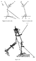
- FIG. 1i and 1ii there is shown a simplified view of one type of known prosthesis 10, comprising a thigh member 17 - complete with insert, also known as a 'socket' 18, a knee 13 and shin 14, in positions of toe-contact but under different circumstance.
- Figure 1i shows the leg in stumble mode, where a swing extension movement is interrupted by sudden toe contact with the ground.
- the body mass In an attempt to prevent a fall, the body mass must be shifted to the prosthesis, whereby to allow placement of the sound limb ahead of the body so that the forward momentum of the body will not result in a fall.
- This figure also shows how the forces pass through the fore-foot in stumble mode - which correspond with the forces that pass through the foot in toe-off mode.
- Figure 1ii shows how the forefoot 11, having a ground reaction force 12 acting through the knee 13 and which would otherwise be a poor location for engagement of the stance phase, except that it enables the knee to commence swing action. It will be realised that during normal swing function, a stance resistance would be most undesirable.
- Any prosthesis will have mass, whether modular or not. Whilst the issue of consideration is the effective weight arising from gravity, a more troublesome issue arises upon use and, in particular, upon a forward swing of the prosthesis. Unlike the downward weight of the prosthesis that remains the same irrespective of distribution of mass, the perception of'weight' in kicking the leg forward with the thighbone is very much dependent on the mass distribution.
- the location of the mass of the foot cannot be altered, and the only way to reduce the inertia is to reduce the mass of the foot, and shoe.
- the situation for the knee joint is quite different, the location of the centre of mass of the knee joint can be brought close to the knee centre (by selecting a small joint), and by selecting a small mass (small knee joint) at a cost of losing function such as stumble recovery, yielding under body weight in downstairs walking, because in engineering functionality typically adds mass.
- known prosthetic knee & limb devices are either light weight - a benefit, with meagre function or safety - a significant disadvantage, but if the engineering requirements are met - a benefit, the inertial mass of the device is too high for comfort - a significant disadvantage, liable to cause unwanted side effects such as the occurrence of friction burns on the distal stump.
- Yuichi US2005015156
- Yuichi claims to teach of an above-knee prosthesis that permits a user to control knee flexion or extension and to enable voluntary lock and release of the knee joint, at any angle of bend, in that it teaches a means to detect forces present in the artificial limb proximal to the knee axis, but not necessarily a means to act to the benefit of the user.
- an objective of Yuichi is to provide a natural gait.
- the prosthesis to Yuichi comprises a thigh frame assembly that receives a thigh stump; a leg frame assembly operably associated with a foot; a hinge interconnects the assemblies to form an artificial knee joint.
- a closed hydraulic system provides variable resistance to the bending of said artificial knee joint in correspondence with anterior-posterior (AP) movement of said thigh stump.
- the AP movement of the thigh stump is conveniently arranged to control a flow rate valve by means of a linkage, sliding or screw assembly.
- the flow rate control valve varies the resistance provided by the closed hydraulic system: pressing the thigh stump backwards within the thigh frame assembly increases resistance and slows knee bending until the knee locks, whilst pressing the same forwards decreases resistance and allows the artificial knee joint to yield to outside forces, such as gravity and/or stump thrust, the prosthesis can pivot freely about the knee hinge.
- Yuichi operates solely on the AP force vectors present in the hip flexion and extension efforts and all embodiments teach of isolation of AP forces from any axial forces, even when the incline of the sensor is slightly tilted, i.e. not perpendicular to the femoral axis.
- Yuichi defines 'AP' in terms of a plane / direction of operation of the sensor device, which makes the discussion about any tilt of this direction relative to the body immaterial.
- Yuichi suggest means of hip musculature (para. 45), despite that fact that in real gait, for example, upon heel strike with the ground, a force vector naturally passes posterior to the knee centre, with reference to Newton's third law.
- the GRF is an important external force.
- the GRF is normally determined by means of a force-plate, which comprises four tri-axial force sensors that measure the force acting between the foot and the ground in 3 axes: transverse (Z), anterior-posterior (X), and vertical (Y).
- Z transverse
- X anterior-posterior
- Y vertical
- the resultant sum of all the reactions from the ground is equivalent to the sum of the four forces measured by the sensors (for more detail, refer to material relating to Biomechanics course 3150 per "BioMedical Engineering OnLine").
- the ground reaction force would start to tilt forward in reaction to a thigh extension reflex, and in accordance to Yuichi's teaching the knee would stabilise and due to the body weight sliding backwards relative to the knee axis, the hydraulic resistance would soon increase to its maximum, but not be under useful voluntary control.
- the AP forces to Yuichi are defined relative to the continually moving reference 'vertical', corresponding to a longitudinal axis of the femur, in alignment with the coronal plane and this is in contrast with any standard medical reference of the term "AP".
- any claimed voluntary control that is possible with such devices with respect to a level of resistance over knee bending in sitting down does not necessarily become apparent in practice and it is believed that the resistive bending moments will have an 'AP' force component equal to the product of the knee bending resist moment and an inverse factor of the distance from hip to knee centre, which for a typical male would correspond to the forces arising from half the weight, say 450N (100Ib force). Because the force returned in the sensor device is equal to the pressure the user exerts on it, the user must also provide such levels of force to the sensor device to get a level of resistance.
- the thigh When walking down a stair, the thigh is at approximate 15° relative to vertical, which means that in the time frame of single leg weight bearing, the 'AP' force component delivered to the control device is only 25% (sin15°) of the body weight, meaning that the resistive torque that slows down the descent of the body will permit a g-force of 75% x 9.81 to act on the body, which would result in an uncontrolled descent.
- Further Yuichi employs the AP plane as per AP plane of the knee device as a means of control, using hip extension and hip flexion forces to control the knee joint's operational characteristic.
- the ground reaction force arising, for example, from any one or more of body weight, resisted body momentum (as arises upon touchdown with the ground), any voluntary muscle actions and any involuntary muscle actions
- the behaviour of the knee device is either indeterminate (that could trigger a muscular reflex spasm not too dissimilar to an experience when one slips upon an icy surface), or biased by a resilient element, whereby, for example to maintain a level of resistance low unless the resilient element is compressed by hip effort and, thus, make the behaviour of the knee device more predictable.
- a GRF is initially tilted backwards, more or less in line with a limb.
- the body is naturally stable if the GRF passes anterior to the knee centre, but the 'AP' force vector from the GRF, is oppositely directed with respect to the hip's 'AP' force vector and in this scenario the 'AP' force vector as per Yuichi would force the knee into stability which would be undesirable.
- the 'AP' force vector-set of shin-and-hip would be opposite and would permit the knee to bend, since the knee would react as if the hip was driving the leg forward. This would result in an immediate knee collapse, followed by a rapid transition to a posterior direction of the 'AP' force by the hip and the knee would find stability again and a fall would be arrested, but all at a cost of unstable performance.
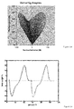
- Fig 1iv is a graph that illustrates mean anteroposterior (Fx) GRF component waveform exerted by right and left (dotted line) in walking at normal speed.
- Fx mean anteroposterior
- the sensing of a bending moment related to loading of the limb may be performed by means of a force sensing resistor mounted between, for example, relatively movable parts in the region of the knee joint, and a particularly preferred arrangement is to place the force sensing resistor between, on the one hand, one end of a lever arm the other end of which is pivoted on a knee chassis member forming part of the thigh part of the prosthesis, and, on the other hand, a resilient element inserted between the lever arm and the knee chassis to provide small amounts of flexion independently of the knee flexion control device.
- Other transducers may be used for producing an electrical signal which is wholly or partly a function of the knee bending moment.
- Blatchford clearly indicates that a means is sought to determine a level of strain around the knee centre to provide the controller with required information of the degree and duration of force, and feedback between resistive force output by the hydraulic controller, so that deviations from the desired levels can be used as input for changing the hydraulic controller's output by altering the state of stepper motor driven valves.
- the sensor in Blatchford is part of an integral electronic control system wherein the sensor provides feedback with regards to the system's response primarily to its own.
- Blatchford provides a clear limitation of operability between 0 - 35° (GB page 2, II.22 - 25), which is believed to arise, at least in part, from the nature of the reaction forces in hydraulic systems and the limitations placed on linear transducers: when the knee bends under resistance over a certain angle, not only does the mechanical leverage over the knee increase with progressive knee angle increasing signal strength in Blatchford's sensor, the shortening lever arm for operating piston with increasing knee flexion requires an ever higher hydraulic pressure inside to produce resistive bending moment to the knee. Nonetheless, when an amputee generates an effort of hip moment, in an attempt to determine the behaviour of the artificial limb, reaction forces in such a sensor will affect the overall response and cause the electronic system to control the damper in an indeterminate fashion.
- inertia arising from a distal element will increase the mechanical force sensed by the sensor, and result in an over-estimate of the level of damping required, which would then reduce its resistance to balance the system response, making the response of the prosthesis too weak.
- a hip extension in a weight bearing condition will necessarily result that could cause an increase or decrease in the level of the force determined by the sensor, in dependence upon a momentary angle of knee flexion, and this would necessarily influence the information received by the electronic system.
- the present invention seeks to provide a solution to the problems addressed above: problems associated with moment of inertia of the prosthetic knee device, the need to switch operational modes of the knee in response to ground reaction forces and body reflexes over a full range of knee flexion.
- the present invention seeks to provide an improved mechanically controlled prosthesis for a short stumped femoral amputee, where 'short stump' is intended to mean a length short enough to locate the centre of mass of the knee joint and its main operable components proximal to the knee centre.
- the present invention also seeks to reduce the level of complexity of control in a prosthesis.
- the present invention also seeks to provide an improved electrically controlled prosthesis for a femoral amputee.
- the present invention further seeks to provide a device that is commercially and clinically relevant, and that adequately deals with the problems apparent in respect of certain prior teachings of the art.
- the present invention further seeks to provide a response independent of a level of anterior - posterior force, as determined by some proponents of the art, with respect to a level of resistance as experienced by the prosthesis.
- a knee joint with a first member that by mechanical fixation of other members forms a prosthesis with a shin and foot component that operate as one unit with respect to the functioning of the knee joint and first member pivotally connected to a thigh member, connection being the effective knee axis, and first member also pivotally connected to a damper on its one end offset from effective knee axis to provide a lever arm for said damper, and said damper pivotally and proximally connected to the thigh member, such that three pivot connections form a triangle, with damper member of variable length in accordance to its function, and operable to allow knee flexion to take place, and a third member pivotally connected to thigh member, pivotal connection advantageously placed proximal posterior to the effective knee axis, and third member being fixed to the stump, and permitting very limited but distinct movement of third member relative to thigh member, and wherein on hip extension and on presence on ground reaction force passing anterior to the said proximal posterior
- the present invention can be provided with sensors and functions to identify ground reaction force vectors passing anterior to a virtual reference point in a similar region as said proximal posterior pivot to similarly be employed to allow a damper to switch state of operability which control the damper units, it is preferred that the present invention operates as a weight activated knee joint but does not operate in a default stance mode; that is to say that the prosthesis is preferably characterised such that body weight needs to be applied to activate a high resistance mode, whereby to stabilise the knee joint.
- the present invention allows not only body weight to activate the stance mode, a hip extension effort exerted on the socket will also activate the stance mode in lieu or in concert with the bodyweight applied to the artificial limb, and hip flexion effort will reduce or negate body weight effects on its mechanism.
- the swing initiation, associated and initiated by hip flexion can overcome any stabilising effects associated with any residual bodyweight applied, and allow the default low resistance mode to permit the swing phase to take place.
- a hip flexion in combination with weight relief from the prosthesis will cause the ground reaction vector to pass posteriorly to the reference point (axis) prior to passing posterior to the knee axis, such that the damper is brought into a state of low resistance motion before any fluid flow within the damper commences, which in case of high resistance mode would maintain high resistance due to positive feedback to damping state within the damper mechanism.
- the weight applied on the prosthesis, as well as the hip extension effort will cause the default swing mode to be switched to the weight activated / hip extension activated stance mode.
- the present invention also provides an activation mechanism for a stance mode by virtue of thigh / hip extension.
- a resistance to a hip flexion in the prosthetic hip joint at angles in excess of approximately 25° will also trigger a high resistance mode and help prevent an imminent collapse of the joint and fall of the prosthesis - and wearer.
- Further advantages can be gained in an electrical control system with the present invention by including data relating to a state of strain from the prosthetic hip as an added input signal for the determination of a control response for a prosthesis.
- a trans-femoral amputee prosthetic knee joint having a centre of mass; wherein the prosthetic knee joint comprises a thigh element, a knee element and a damper; wherein the thigh element is provided with a proximal attachment device, whereby to attach the prosthetic knee joint to an amputee stump interface; wherein said knee element provides an effective knee axis distal to the centre of mass of the knee joint, throughout its range of movement, to allow movement of said knee element about said effective knee axis relative to said thigh element and wherein the said knee element is provided with a distal attachment device whereby to enable attachment with respect to a shin and foot of prosthesis; wherein there is also associated with said thigh element a damper to provide at least a bimodal level of control to movement of the thigh element relative to the knee element; wherein the damper is arranged to provide control to movement without substantially affecting the component of inertia arising from the mass of the damp
- the shin element In use, with a person having a thigh-stump that is moveable about their hip, to enable movement with respect to a ground via a shin element associated with the prosthetic which in use, bears upon the ground support surface.
- the shin element is pivotally connected to the thigh about the knee axis of the knee element and movement of the shin element with respect to the thigh element about the knee axis is operably controlled by the damper element, whereby to enable control of movement of the shin element with respect to the thigh element about the knee axis.
- the shin element has a foot element operably associated with the distal end, being connected by way of an ankle, which preferably provides a limited extent of movement.
- a trans-femoral amputee prosthetic knee joint having a centre of mass; wherein the prosthetic knee joint comprises a thigh element, a knee element and a damper; wherein the thigh element is provided with a proximal attachment device, whereby to attach the prosthetic knee joint to an amputee stump interface; wherein said knee element provides an effective knee axis distal to the centre of mass of the knee joint, throughout its range of movement, to allow movement of said knee element about said effective knee axis relative to said thigh element and wherein the knee element is provided with a distal attachment device whereby to enable attachment with respect to a shin and foot of prosthesis; wherein there is a damper associated with said thigh element to provide at least a bimodal level of control to movement of the knee element relative to the thigh element; and, wherein the damper has a mass with a centre of mass being proximal relative to the knee centre; whereby the damper is oper
- the present invention overcomes the shortcomings of the prior art by reacting to the ground reaction force as a vector per se, rather than merely the magnitude of the force vector or merely a single directional component thereof. Applicant believes that this is materially different, beneficial and distinct.
- the present invention provides a mid-thigh prosthetic flexible or hinged region that is placed such that a ground reaction force passing posteriorly, is operable to cause the mid-thigh-hinged-region to flex (direction of flexion as direction of knee joint flexion) and vice versa - in the sense that a force vector passing anteriorly to the mid-thigh-hinged-region can cause the mid-thigh-hinged-region to extend (direction of extension as direction of knee joint extension).
- the present invention can thus provide a smooth operational function and there is no graduated control over the state of the knee device in present invention.
- the mid-thigh-hinged-region reacts purely on the direction and path of the ground reaction force, and its location is chosen such that the ground reaction force will always pass anteriorly during heel strike, mid stance and only during toe-off, when the weight of the user is withdrawn from the limb and hip flexion commences that the mid-thigh-hinged-region to flexes to release the hydraulic damper from an activated high resistance back to a low level of resistance. In this way erratic hip flexion effort in the presence of excess residual body weight on the limb cannot cause the knee to become unstable.
- present invention there is complete a separation between control of resistance and the on-off state of the type of resistance.
- the stance resistance is distinct in character and state to the resistance to swing, and the switching between states is controlled by the forward or rearward passing of the ground reaction vector past an auxiliary axis, and seeks no voluntary control:
- present invention uses the typical ground reaction forces and reflexes as occur in normal amputee gait, and these without any voluntary effort.
- the present invention provides an option for sensor information from the more distal components, especially sensors about the ankle region, to provide feedback signals which together with information relating to the main knee joint as a centre of mass proximal to the effective knee centre whereby to provide a operable to further control knee joint response.
- the present invention can also be arranged to determine data arising from sensors associated with an artificial hip joint in case of a hip disarticulation prosthesis.
- the knee joint operates as a weight activated knee joint.
- the damper is a hydraulic damper.
- the damper movement in one embodiment is wholly arranged proximate (i.e. as close as possible to) the stump receiving portion of the prosthesis, and substantially proximal to the effective knee centre, with a mechanical movement transfer mechanism operable to transfer pivotal movement from the knee axis to a second pivot element proximate the stump receiving portion, the distal portion of the damper being connected with the second pivot portion.
- the damper is a linear hydraulic damper it can be operably mounted perpendicularly to an axis of the thigh, with the mechanical movement transfer mechanism comprising one or more of the following: a connecting rod, a chain, a wire and a roller/gear assembly, whereby pivotal movement of the knee axis is translated into a reciprocating linear and/or pivotal movement proximate the stump receiving portion of the thigh.
- the knee joint can also be of polycentric design if its centre of mass is proximal to the effective or virtual or instantaneous knee centre (as defined in full extension of the joint).
- the thigh element can be comprised of two elements connected by means of a pivot providing an auxiliary axis to the second element; a first proximal element that operably couples with the stump and the second, distal element that operably couples with the shin, the articulation point being posterior to the knee axis, such that a line centred from the articulation point, passing through the knee axis will intersect the foot; the movement associated with the auxiliary axis can be used to control the damping means.
- the prosthetic limb is provided with a thigh element which further comprises an electrical circuit with strain gauges and means to control the damper, the strain gauges being placed on anterior and posterior aspects of the mid-thigh such that, in use, they are operable to determine the flexural properties of the prosthesis and, in the event that strain in the posterior strain gauge represents stretch relative to the strain measured in the anterior strain gauge, an electrical signal can be employed to change or maintain a bimodal state of the damper, the damper being centred about the knee axis in case of a rotary design or substantially proximal to the knee centre, such that the centre of mass of the knee joint as a whole is proximal to the knee centre.
- the electrical state of the strain gauge can be employed to control a solenoid valve or a magneto-rheological fluid associated with a damper, whereby to control a state of the damper.
- the prosthetic limb is provided with a thigh element further which comprises an electrical circuit with pressure/strain sensors and means to control the damper, the pressure sensors being associated with the stump receiving element such that, in use, they are operable to determine the flexural properties of the prosthesis such that, in the event that pressure upon anterior portion of the stump is greater than the pressure upon a posterior portion of the stump, an electrical signal can be employed to change or maintain a state of the damper, the damper being centred about the knee axis in case of a rotary design or substantially proximal to the knee centre, such that the centre of mass of the knee joint as a whole is proximal to the knee centre.
- the electrical state of the strain gauge can be employed to control a solenoid valve or a magneto-rheological fluid associated with a damper, whereby to control a state of the damper.
- the electrical state of the strain gauge can be employed to control a solenoid valve, whereby to control a state of the damper or to control a magneto-rheological fluid associated with a damper, whereby to control a state of the damper.
- the shin element has a foot element operably associated with the distal end, being connected by way of an ankle, and preferably, the ankle provides a limited extent of movement, the damper being centred about the knee axis in case of a rotary design or substantially proximal to the knee centre, such that the centre of mass of the knee joint as a whole is proximal to the knee centre.
- the knee axis can comprise a compound joint with two effective axes, operable in succession during a pivot movement about the knee.
- the damper is conveniently provided as a hydraulic damper having a cooperating piston and cylinder assembly, preferably operating in a rectilinear fashion, with the proximal end being pivotally fastened with respect to the proximal thigh section.
- the present invention also provides a prosthetic limb with a knee axis, and a proximal shin portion - the knee-cap, to receive a remainder of the prosthesis, comprising merely the shin and foot, with no significant and relatively massive damper elements.
- the nature of modern modular design of limb prostheses assures that the present invention can be enabled using many elements that are presently used in leg prostheses and thus not only are they generally available, there is substantial know-how associated with their use.
- the present invention provides a mid-thigh articulation point, located approximately between the knee centre and the anatomical hip, which articulation point provides a coupling for the damper, which articulation point is posterior to the knee axis, such that a line centred from the articulation point, passing through the knee axis will intersect the foot.
- articulation point/knee axis line intersects the foot approximately mid-foot.
- the foot, the bent knee and the stump receiving socket will need to be the strut that takes the weight of the patient for a brief moment to allow the other foot - typically a healthy foot - to be lifted off the ground to be positioned such that balance can be restored.
- the reactive and reflex type of stump hip extension will trigger the high resistance mode, and the controlling damper will maintain the high resistance state for the necessary duration.
- a prosthetic leg with a knee joint offers the benefit of considerably reduced inertia arising from the knee joint.
- the benefit arises from an advantageous positioning of components having great mass being placed as close to the stump as possible although not necessarily diminishing the weight of the prosthesis per se.
- inertial effects of pivotable mass increase in proportional to the square of the distance to the pivot axis, being the hip joint.
- the present disclosure completely separates the response from the hydraulic controller from the ground reaction vectors that control the bi-modal state of the hydraulic controller. This is best illustrated by considering the knee joint to be in a state of flexion of say 90°. A hip extension effort by the amputee using the device of our disclosure, whereas indeed providing a signal to the controller to change state from low level of resistance to high level of resistance, such as to "provide small amounts of flexion independently of the knee flexion control device" the change to high level of resistance in present invention will immediately remove the said "small amounts of flexion” due to the transference of resistive knee movement to the auxiliary axis in present invention causing an immediate small amount of extension, whilst the controller maintains its state of high resistance through internal means. Sensor or means in our disclosure is a primer for change of state of system from low level of resistance (typically for swing phase) and high level of resistance (typical for stance phase). The prior art discussed above cannot provide this functionality.
- the prosthesis of present invention may incorporate in a knee joint, with a centre of mass proximal to the effective knee axis, microprocessor controlled features such as gyroscopes, tilt switches, GPS positioning systems, reed relays or other means to determine a desired state of operation.
- microprocessor controlled features such as gyroscopes, tilt switches, GPS positioning systems, reed relays or other means to determine a desired state of operation.
- Such hydraulic features can also be implemented with stepper motor controlled valves or rheo-magnetic fluids. Benefits of the present invention will naturally arise from a proximal positioning of more densely weighted components with respect to a hip of a user.
- the knee joint is a dismountable and exchangeable part of a whole leg prosthesis, and whereas it is operable to move other parts of the prosthesis such as the foot in mid-swing, and operable to lower the mass of the user's body down a stair, it is a distinct modular device with a proximal and a distal end which are the boundaries of the space envelope of the knee joint per se.
- a modular joint as a product and device, has a centre of mass, and prior art modular knee joints have their centre of mass distal to the knee centre (or knee axis) these are operable about.
- the weight of a modular joint is frequently declared in the sales literature.
- prosthetic components Parts of a prosthesis like a foot, shin tube, torque absorbers etc. are referred to as prosthetic components, which are necessary to build a prosthesis, but are separate to present invention. These components need to be moved throughout space during swing phase of the prosthesis, and the precise movement (with particular reference to the angular relationship between these components relative to the stump attachment device) is controlled by the operable means of the knee joint.
- This operable means of the knee joint has its own centre of mass that can be identified in isolation to any housing or exoskelatal part of the knee joint.
- hip disarticulation prostheses will be understood to count as a special form of short transfemoral amputation prosthesis.
- Thigh flexion when person faces leftwards, a clockwise motion of the hip is called hip flexion, similarly when person faces leftwards, a clockwise motion of the distal thigh about a mid thigh flexural region is called thigh flexion for the purposes of this specification.
- a movement about a mid thigh hinge or flexible area to determine direction of strain or displacement will be called thigh flexion, needs to be defined for the purposes of consistency, and in this specification the distal half of the prosthetic thigh, when moving in the same sense as the femur moves relative to the trunk will be called mid-thigh flexion. Accordingly, a hip extension effort causes 'thigh flexion' if the knee axis is restrained by force or by inertia.
- Thigh joint a flexural or hinged movement within the mid third of a distance between hip joint and knee axis, or such movement purposefully distanced from both hip joint and knee joint to be meaningfully distinct from either in terms of operability of distinguishing force patterns particular to passing through mid thigh region.
- Prosthetic leg a prosthetic leg including a knee joint, also including a hip joint in case of a hip disarticulation prosthesis, in which case, the term trans-femoral amputee shall also be assumed to include those amputees having little or no femur.
- Proximal and distal shall follow normal human anatomy convention, with the head as the base of reference.
- a first embodiment of the invention comprising a prosthetic limb assembly 20 comprising a foot member 21, a lower leg / shin member 24 and a thigh member 27.
- the shin and thigh members are hingedly connected one with respect to the other at respective upper and lower positions (in normal, standing/sitting use by a patient) by means of a knee joint, which pivots about a knee axis 23; a lower part of the shin member 24 is connected to a prosthetic foot and at its top to the knee joint by means of a industry standard pyramid coupling whilst an upper part of the thigh member is connected by similar pyramid coupling system to a stump receiving element or sleeve 18, operable to receive the stump of a trans-femoral patient.
- a knee joint is defined as to be the apparatus between its coupling interfaces, and in that of modular design.
- Sleeve 18 may also represent a bone anchor abutment.
- the thigh in this first embodiment comprises two elements; a lower element 27L connected to the knee at a distal end about axis 23 and to an upper section 27U by means of a pivot having an auxiliary axis 29 to allow for a small but operable range (preferably less than 2 degrees) of thigh flexion and extension; the proximal end of the upper element 27U being associated with a femoral stump and or stump receiving element 18.
- Auxiliary axis 29 allows pivotal movement about itself or, to the same, axis 46 in Figure 4iii , to allow the exposure of strain forces in the thigh element 27 associated with thigh flexion and extension: a difference between a posterior compressive strain and an anterior compressive strain will cause 27U to approach 27L unless the anterior strain is null or tensile.
- both systems can make operable the applied weight and the location of its ground reaction force vector on the prosthesis as in ordinary weight acceptance in heel strike with a fully extended knee joint, or both systems can make operable a hip extension effort as applied on the stump receiving element 18 (also known as the socket), wherein making operable means the changing of state of the resistance to movement of knee joint by the damper.
- the embodiment can be that of strain gauge to support digital or electrical signal processing, or the embodiment can be mechanical to support direct valve control
- the word strain can be suitably interpreted to have the same meaning for any embodiment that makes hip extension operable by making effective the strain in the thigh element.
- thigh flexion occurs prior to a change of state of the knee joint and occurs in a state of high resistance.
- a thigh extension supports a low level of knee flexion resistance depending on the immediate preceding history of knee movement.
- a damper 22 is connected at one end 22L to the knee-end of the shin, which rotates about the knee axis with respect to the thigh and is connected at a second end 22U associated with the upper prosthetic thigh element 27U, closely spaced with respect to the femoral stump 18.
- the articulation point 29 is posterior to the knee axis, such that a line centred from the articulation point 29, passing through the knee axis 23 will intersect the foot.
- the said articulation point/knee axis line intersects the foot approximately mid-foot.
- Member 27U pivoting about axis 29 is ideally limited in it pivotal movement to 1 - 2°, and this movement is ideally cushioned on the ends of the stroke.
- the present invention is also distinct in its operation with respect to known systems, taking advantage of the strain forces present in the thigh structure distal to the stump proximal to the anatomical knee centre, in fact, proximal to the centre of mass of the knee apparatus, centre of mass of knee apparatus proximal to the knee centre 29, to provide benefits in stumble recovery, as shall be discussed below.
- member 27U that is permitted about this mid-thigh articulation point 29, can be used to switch the mode of operation of the damper to reduce fluid flow on the application of weight upon the prosthesis that causes thigh flexion, in particular member 27U abuts a resilient switch activation element in the proximal part of damper 22.
- the mechanism within the damper 22 is activated or primed by member 27U, to cause a high resistance function and associated high oil pressure within damper 22.
- the hydraulic fluid under a condition of high pressure maintains the primed valve in a closed state for the duration of sustained high pressure. This is corresponds to a normal mode of operation, wherein there is a high resistance to bending under body weight bearing after application of body weight on the prosthesis.
- member 27U may discontinue its priming function, as the high resistance condition is maintained.
- member 27U moves away from frame 27L, whereby to ensure that the damper valve is not primed, whereby there is a reduced, low level state of resistance to bending, enabling swing phase.
- the valve of damper 22 can be activated at any time through thigh flexion to reduce movement and prevent collapse.
- a ground reaction vector is directed through the heel, and provides a self-stabilizing force if the vector passes in front of the knee centre.
- the ground reaction passes posterior to the knee centre and anterior to the thigh joint centre, then this provides an unstable condition; the knee shall become unsupported and shall have a tendency to collapse.
- the ground reaction force acting anterior to the thigh joint will cause the valve to become closed and a tendency to collapse of the prosthesis will be thwarted.
- the damper In being positioned above the knee centre, the damper contributes to an efficiency of movement, by the expediency of having the centre of mass of the prosthetic limb closer to the hip whereby the damper, effectively only needs to control the movement of the attached shin and foot and not that of its own mass, allowing a more controlled swing movement since the mass of the shin element comprised of foot 21 and light weight tube 24 will be much reduced relative to the prior art, wherein the knee joint is part of the knee-shin-foot complex that is in need of kinematic control, allowing for more precise movement control with the short residual limb.
- the degree of control improves in a two-fold fashion because a reduced force means reduced soft tissue compression, increased proprioceptive feedback (since nerve endings are not stimulated to maximum) and a better mechanical coupling between bone and stump receptacle.
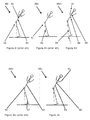
- the auxiliary pivot axis 29 is effectively proximal to the knee axis as well as proximal to the centre of mass of the knee joint, and posterior to the hip knee ankle line in contrast to known systems (like in Figure 4ii ), where the angle between, on the one hand, a plane passing through the knee axis and the auxiliary axis 45 (as exemplified by the Otto Bock 3R80 knee joint) and, on the other hand, a line passing through knee axis and ankle would remain substantially constant, independent of an actual extent of knee flexion.
- the angle between the line through knee axis and ankle and a plane through knee axis and auxiliary axis 46 increases proportionally with respect to knee flexion (as in Figure 4iii ) (Planes not shown).
- knee flexion as in Figure 4iii
- the push power of the residual limb is diminished in a number of ways. Firstly, the mechanical engagement in the socket of the leg is relatively poor, as the short bone is diffusely wrapped in soft tissue such as muscle, fat and skin, leaving poor quality control to the stump. Secondly, the short stump will quickly build up high reaction forces on the distal bone, which by means of pain and friction soon becomes a limiting factor to further movement. Thirdly, in normal walking, the angular travel of the hip is relatively constant and therefore the available 'travel' of the distal stump in an arc about the hip joint is limited. Additionally, it will also be appreciated that the gait will not be natural, which will also have an effect on efficiency.
- an artificial limb can be modelled as a mass that needs to be brought forward by means of swinging action. This incurs a need to accelerate the mass of leg, which means a gain of kinetic energy, and the subsequent deceleration of the same mass means a loss of such kinetic energy. This energy is dependent on the "velocity per distance travelled" profile of the mass. This can be considered as the energy turnover.
- FIG. 3 which is a graph of energy turnover (Y-axis) (arising from the cyclic forces of acceleration followed by deceleration) versus distance of mass centre from the hip joint, for a reference mass M of 1 kg (2.2Ib) at a distance L from the hip joint (X-axis) will require at a step length of 0.8m in 1 sec (standard reference walking speed) in the (simplified condition that the leg is stiff) an estimated acceleration energy turnover, when the arc of motion is limited to 30° for all cases of location of centre of mass.
- PA01 Primary-Art 01
- DC01 Disclosure 01
- PA01 Primary-Art 01
- DC01 Disclosure 01
- PA01 Primary-Art 01
- DC01 Disclosure 01
- the mass of knee as in present invention does not need to be driven forward through a loss making process such as hydraulic damping, further gains in efficiency are obtained, which will further reduce the amount of energy expended , and making available more energy from the stump action to be 'utilised for effective kinematic movement'.
- the stump has to swing a prosthesis forward, which means swinging a foot complex forward and associated knee joint.
- a foot element to the prosthetic would be an independent variable with respect to the invention but, in contrast, the knee is a controllable (dependent) variable.
- knee joint mechanisms Whilst known knee joint mechanisms are, in terms of their operable centre of mass distal to the knee centre, and its associated mechanism require a certain amount of energy from the stump to swing itself forward. This energy is obtained as the residuum of energy put into the damper, and is a function of the damper loss-factor. Since the energy required to swing the mass of a knee joint that is distal to the knee axis is fixed by the kinematics of walking, the loss factor involved from hydraulic dampening acts reciprocally.
- the centre of mass of the operable knee joint is proximal to the knee centre, then not only does the knee joint take less energy due to diminished acceleration and deceleration in association to hip angle ⁇ h but also reduces the force amplification factor as outlined above: the stump can swing the operable knee joint mass direct without hydraulic energy loss to be moved through swing. To the contrary, all energy passing out of the damper is fully available to swing the residual shin and foot complex, which represent mass that cannot be brought closer since the foot must engage with the ground.
- the level of force acting on the distal stump places a limit upon the amount of energy that can be provided to the system, in such a way that a Long Stump may have a high limit to energy output LS01, and a Short Stump will have low limit energy output SS01. These limits cannot be comfortably exceeded.
- Figure 4i shows a system where there is no provision for stumble recovery. In walking or running a ground reaction force will pass through the low resistance gait being a simple joint). The femoral stump 41 would attempt to resist the forced flexion of the short stump indicated by arrow 49, but would fail for lack of strength.
- a weight activated joint is shown, where the joint is brought into weight bearing mode only if the ground reaction force passes posterior to the auxiliary axis 45 of the shin 44, although this is not the case in this prosthesis, because the GRF must pass through the knee axis until high resistance is created, but high resistance cannot be created because the GRF passes not posterior to axis 45, necessary to trigger high resistance.
- Figure 4iii unlike Figure 4ii , shows a prosthesis with a mid-thigh hinge joint 46 having a limited range of motion (1 - 2°), conveniently not restrained by a resilient member other than the provision of soft end-stops to the range motion (not shown).
- the mid-thigh hinge joint 46 would be caused to move (thigh flexion) under the application of weight upon heel strike and would also be caused to move upon any extension effort in the hip acting on the stump in an attempt to recover from a collapse following a stumble (weight application on the artificial limb prior to full extension).
- both the ground reaction force (passing through the knee centre) and the amputation stump would attempt to resist any forced hip flexion, forced by the shin member pushing onto the knee axis, which would cause the auxiliary joint 46 to close (thigh flexion) and provide signal or priming for a hydraulic knee joint to change state from low resistance to high resistance.
- Figures 4iv and 4v show legs suitable for electronic control, in which strain gauges can be provided for electronic control.
- Figure 4iv shows an example typical of legs produced by Otto Bock in their relatively expensive computer controlled C-leg, where a default stance joint is informed by strain gauge 47 about the ankle.
- this joint Were this joint to be a free swinging joint and operate in stance mode by weight activation, as short stumped amputee's desire, then this joint would not offer any stumble recovery without complex software comparing expected movement with actual movement.
- the extent of knee flexion could be used as a signal input, such an observation is difficult to distinguish from knee flexion at an initial point in the swing phase.
- the relative strain in the strain-gauges will be reversed and an associated electronic signal processor will take this into account, noting that in the instance the ground reaction force passes through the knee centre, the anterior strain gauge will be in a state of tension relative to the state of the posterior strain gauge which will be in compression, even after taking into account any correction for neutral compression due to residual weight.
- auxiliary axis or strain gauge
- the ground reaction force entering the fore foot passes through the knee centre forcing the hip to flex, whilst the hip tends to resist this flexion and in so doing causes a resilient member associated with the auxiliary axis to be compressed, or at least the respect elements of a prosthetic bone to hinge about their auxiliary axis.
- the compression of the resilient member and/or associated movement allows the activation of a hydraulic circuit closing valve, and the closing of said valve increases the hydraulic resistance of the knee-joint, which tends to maintain a state of closure of said valve via a suitable means of feedback to the valve.
- an auxiliary axis is advantageous in that it can relatively easily be manufactured and operate with relatively simple, non-electrical system.
- an electrical equivalent can also be provided.
- an equivalent arrangement utilising an electrical circuit with strain gauges could determine the flexural properties of the prosthesis about the mid thigh location.
- the set of strain gauges would be advantageously placed on anterior and posterior aspects of the mid-thigh prosthesis. In the event that strain in the posterior strain gauge represents stretch relative to the strain measured in the anterior strain gauge, even if both would be in compression, then there would be an electrical equivalent to the thigh joint being in a state of extension.
- the electrical equivalent to sensing state of thigh with respect to flexural tension could then be utilised to control a valve that, in turn would control the state of the damper.
- a suitably programmed microprocessor could be employed to operate a solenoid driven valve to enable priming of the change in state of the knee joint, to provide a computer-controlled prosthesis.
- Polycentric joints are those where multiple joints are used that together create a virtual centre of rotation, or effective knee centre, (n.b.: the effective knee centre in a uniaxial joint is the uniaxial joint axis) to act as a knee centre all the same, and stump effort sensing gauges or operable movements are all anticipated by this disclosure.
- a knee joint with a dual axis or polycentric may be determined to provide improved flexibility as shown in Figure 5 .
- an exemplary knee is shown generally at 50.
- the lower leg, the shin 24, together with knee-cap 51 is conveniently articulated with respect to the prosthetic thigh structure 27L whereby the two prosthetic members act, primarily for reasons of simplicity and reliability.
- the prosthetic thigh is preferably articulated with the knee cap about a single axis knee centre 53; the knee cap also has pivotal attachment at 60a to a piston and cylinder assembly further referred to as the damper 22, which damper has its proximal articulation with the proximal thigh.
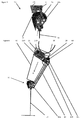
- FIG. 6 there is shown a second embodiment of the invention, wherein the articulated prosthetic thigh 67, 27U having a axis 29 to provide a small amount of pivotal movement of the upper unit 27U relative to the lower unit 67.
- the damper 22 is shown as being oriented effectively perpendicularly with respect to the axis A of the thigh.
- connecting rod 60 fastened at a first, lower end to the knee 50 about articulating connection 60a and at a second end to a pivot point 60b which is mounted upon a pivot member 69, which enables the pivot movement about the knee axis to be transferred to an upper part of the thigh, whereby to further transfer the mass of the leg toward the pivot point of the leg, the hip, further improving the benefits of the invention.
- a simple connecting rod is shown, it can easily be replaced by meshed gears connecting the pivot point of the knee to the pivot point of the lower point of the damper.
- Figure 7a shows a prior art prosthesis with 89 hip and femur as part of the residual limb contained in socket 88, an arbitrary boundary 91 distal to which there is a knee joint extending to another arbitrary boundary 90 distal to which there is a shin element 81, foot element 80 and inertia of foot and shin 82.
- Prior art prosthesis has knee joint between boundaries 90 and 91 featuring effective centre of rotation 87, whereby effective centre 87 may be a distinct knee axis of pivotal nature, or may be an instantaneous knee centre known from polycentric knees where the effective knee axis is found by the intersection of the relevant members of the polycentric knee joint, said range of instantaneous knee centres in dependence of knee flexion angle defined as a curve (see good publication made by Van Veen), but for the purposes of this description the range of instantaneous centres of the polycentric joint can be contained in a region 87.
- Knee joint has centre of mass 83 distal to 87, and means 85/94 to mechanically or hydraulically couple members of knee proximal to knee centre 87 and distal to region 87, with 94 indicating the location where the resistive torque of the knee joint contained within boundaries 90 and 91 is delivered in case of a piston and cylinder type of damper 85.
- a rotary type of damper about knee axis 87 easily replaces damper 85 to no consequence of presentation of prior art.
- Figure 7b shows a prosthesis in accordance with the present invention, where hip and femur 89, comprising the residual limb bones, are seated within socket 8, connected via knee joint 87 to lower leg (shin) 81 to which foot element 80 is attached.
- First and second arbitrary boundaries 91, 90 are indicated, respectively, distal to socket 88 and distal to the knee joint.
- the knee joint of the prosthesis features an effective centre of pivot 87, whereby effective centre 87 may be a distinct knee axis of pivotal nature, or may be an instantaneous knee centre known from polycentric knees where the effective knee axis is found by the intersection of the relevant members of the polycentric knee joint, said range of instantaneous knee centres being in dependence of knee flexion angle defined as a curve (see good publication made by Van Veen), but for the purposes of this description the range of instantaneous centres of the polycentric joint can be contained in a region 87.
- the knee joint has a centre of mass 84 proximal to 87, and coupling means 86/95 to mechanically or hydraulically couple members of knee proximal to knee centre 87 and distal to region 87, with reference numeral 95 also indicating the location where the resistive torque of the knee joint contained within boundaries 90 and 91 acts in the case that a piston and cylinder type of damper 86 is employed.
- a rotary type of damper about knee axis 87 could alternatively be employed instead of damper 86 with no consequence to the method of operation of the present invention.
- the movement in swing can be generated by a hip flexing movement, in particular, a hip flexing moment by femur 89 that pushes the knee anteriorly A, and the inertia of the masses 84 and 82 must follow, mass 84 necessarily follows by reason of the direct connection with socket 88 and mass 82 follows in a pivot fashion about knee centre region 87, and knee joint between boundaries 90 and 91 shows knee flexion in swing, and movement of knee flexion, and consequently the anterior acceleration of inertia 82 comes about through resistance of damper 86 and the torque 95 it produces.
- the boundaries 90 and 92 that define the knee joint as contained between are truly arbitrary but kept the same, and in case of dispute the knee joint of our disclosure will be defined as a knee joint with all the parts as necessary to remove from one prosthesis to another such as to reproduce the function, inclusive of all accessories like batteries and power supplies and proximal and distal attachments, that by example consist of the typical pyramid connection system as known to those skilled in the manufacture of prostheses, and such knee joint of our disclosure will have a centre of mass proximal to the knee centre at a distance of at least 10.5% of hip to knee centre in the prosthesis, such as to avoid hair splitting discussions with reference to some very small safety knees that may feature a centre of mass a few millimetres above or below the knee centre.
- This number of 10.5% represents a ceterus paribus equivalent reduction of moment of inertia by 20% which is significant enough to be distinct, and 10.5% represents typically 4 - 5 cm which can be easily determined in a prosthetic workshop as
- the knee joint as per its own boundaries (terminal ends) 90 and 91 is suspended from these ends by thin cord 103 from a point 100 so that terminal distal end 90 and proximal end 91 are on a common horizontal.
- the present invention ensures that, in the event that the ground reaction force passes posterior to the thigh joint - so as to permit thigh movement and thus flexion about the knee - then the body weight for passing through the foot cannot control the valve and bring it to a closed position.
- a reflex action of the stump will urge the ground reaction force to pass in front of the thigh axis, whereby to cause thigh extension, which extension increases with an increase in flexion.
- hip extension effort to arrest collapse this would purely arise through such an extension and not arise from a specific mode of operation of any hydraulic valve upon the condition of resisted eccentric hip flexion, or resisted concentric hip extension during initiated collapse of the knee joint.
- the present invention allows the use of thigh extension to arrest further collapse of the knee joint in a condition of partial knee collapse.
- the knee joint would suddenly increase in torque resistance, then the inertia arising from the mass of the falling body associated with the artificial limb, would cause the thigh joint to lose its ability to maintain operation of the valve.
- This fixed relationship maintains the GRF to pass anterior to A1 with no option for the stump to bring the GRF posterior to A1, therefor stumble recovery is not possible.
- auxiliary axis A2 is employed the GRF will pass through T and K, but anterior to A2, a requirement to activate stumble recovery, and as knee flexion angle Q changes so does angle B2 between T-K and K-A2.
- the prosthetic thigh could be connected to a socket that wraps around the leg stump as to connect knee joint to the body, a thigh plate may be provided, which could be fixedly associated with a bone anchor, typically placed percutaneously into the distal femur of the residual limb or stump.
- a bone anchor typically placed percutaneously into the distal femur of the residual limb or stump.
- the present invention can provide a separation between control of resistance and an on-off state of resistance.
- a less favourable, less desired and stripped down implementation can be provided in a poly-centric mechanism, where the body of the knee joint is placed between the distal stump receptacle (socket) and virtual knee centre.
- a severe loss of functionality is encountered as would have been provided by a damper element and damper element must be understood as being replaced by the friction in the device.
- a knee joint will be understood to be a modular knee joint as known to those in the art of making leg prostheses, typified with proximal and distal couplings to connect to other limb components in accordance to the choice of medical specification. Therefore the definition of mass distribution of the knee joint will take into account the centre of gravity of the knee joint in its decoupled state as prior to be built into a final prosthesis.
- Boender provides a weight activated knee joint, with a chassis distal to the knee centre, wherein applied body weight causes a valve to be closed, and the hydraulic pressures within the system upon closure maintain valve closure as long as bending moment on the knee is maintained.
- this concept is like shown in fig 4ii , and is distinguished from the present teaching on two accounts: namely the hydraulic system in prior art is located distal to the knee axis, and this prior art has no means to bring the hydraulic system in a state of high level damping on the occurrence of interrupted swing extension resulting in a stumble when weight is place upon the forefoot (causing to support swing release).
- Boender teaches of a knee joint with fluidic control EP2339995 where in a valve maintains the knee joint in a default state of high resistance, which prior art can only be brought into a state of low level damping upon flexing the knee whilst weight bearing on the forefoot, which as discussed above is a problem for the short stumped amputee because the hip flexion effort must overcome this residual body weight on the prosthesis to allow swing to commence, and certainly, the centre of mass of all shown and specified embodiments is distal to the knee centre forcing the situation that the knee joint must not only control the kinetics of the foot but also its own kinematics, which issue is not of concern in the present invention.
- EP2478875 teaches of a prosthesis with movement lock, wherein two displacement signals are used to control the state of the knee joint and there is neither any hint nor suggestion to positioning a damper proximal to the knee centre nor any form of advantage realized there from. Further it relates to a default stance knee joint that on account of two signals permits a low level of resistance to act, whereas present invention requires only one signal to allow the joint to switch states of operability.
- the present invention makes provision for the high torque in the knee joint to maintain valve closure after removal of the priming input of the thigh extension, even when thigh extension changes suddenly to thigh flexion after the knee joint has become rigid.
- the invention provides the amputee with a short stump an improvement that has been overlooked whereby to utilise space for elements used in knee joint control above the main knee centre.
- damper 22 controls all distal inertia but none of its own (the reactive inertia of the piston rod itself provides part of the controlling force to the distal inertia of shin 24 and foot 21!).
- the inertia of the damper is excluded from the inertia controlled by the damper.
- the damper end connected to the shin element will move at the same angular speed of the knee joint / shin, and be subject to itself in terms of controlling its rotary motion about the knee axis.
- the centre of mass of such a knee joint has been located distal to the effective knee centre which causes the centre of mass of prior art to be subject to be part of the inertia of which movement the damper is set out to control.
- One peculiar property of the prior art is that the centre of mass on progressive knee flexion comes closer to the amputee stump attachment means, especially with reference to the longitudinal axis of the stump, or alternatively more posterior to the same axis as knee flexion progresses.
- the invention substantially removes the issue of the gaining and losing momentum in the shin region of the prosthesis by removing mass from that region of the prosthesis, and instead bring as much as possible operable mass proximal to the effective knee joint axis.
- This arrangement can thus be considered such that the centre of mass of the knee joint makes neither significant excursions in a proximal - distal sense with reference to either amputee hip joint, or stump attachment device, or thigh component of the knee joint, nor will there be significant A-P excursion relative to the same on account of the knee joint, and in this way any contribution from the knee joint towards gait deviations on account of momentum absorbed and returned by the knee device is brought to a bare minimum.
Landscapes
- Health & Medical Sciences (AREA)
- Transplantation (AREA)
- Heart & Thoracic Surgery (AREA)
- Oral & Maxillofacial Surgery (AREA)
- Engineering & Computer Science (AREA)
- Biomedical Technology (AREA)
- Cardiology (AREA)
- Vascular Medicine (AREA)
- Life Sciences & Earth Sciences (AREA)
- Animal Behavior & Ethology (AREA)
- General Health & Medical Sciences (AREA)
- Public Health (AREA)
- Veterinary Medicine (AREA)
- Orthopedic Medicine & Surgery (AREA)
- Prostheses (AREA)
Applications Claiming Priority (1)
| Application Number | Priority Date | Filing Date | Title |
|---|---|---|---|
| GB201504242A GB201504242D0 (en) | 2015-03-13 | 2015-03-13 | Improvements in or relating to prosthetic joints |
Publications (2)
| Publication Number | Publication Date |
|---|---|
| EP3067018A1 true EP3067018A1 (de) | 2016-09-14 |
| EP3067018B1 EP3067018B1 (de) | 2019-08-07 |
Family
ID=53016053
Family Applications (1)
| Application Number | Title | Priority Date | Filing Date |
|---|---|---|---|
| EP16020083.8A Active EP3067018B1 (de) | 2015-03-13 | 2016-03-14 | Verbesserungen an oder im zusammenhang mit prothetischen beinen |
Country Status (3)
| Country | Link |
|---|---|
| US (1) | US10531966B2 (de) |
| EP (1) | EP3067018B1 (de) |
| GB (1) | GB201504242D0 (de) |
Cited By (1)
| Publication number | Priority date | Publication date | Assignee | Title |
|---|---|---|---|---|
| CN110868964A (zh) * | 2017-05-12 | 2020-03-06 | 埃索欧耐迪克超动力 | 外骨骼、矫形器、可穿戴设备或使用磁流变流体离合器装置的移动机器人 |
Families Citing this family (7)
| Publication number | Priority date | Publication date | Assignee | Title |
|---|---|---|---|---|
| DE102017000902A1 (de) * | 2017-02-01 | 2018-08-02 | Rhefor Gbr (Vertretungsberechtigter Gesellschafter: Arno Mecklenburg, 10999 Berlin) | Elektromagnetisches Verriegelungselement für eine Gelenk-Orthese oder Gelenk-Prothese |
| JP6734003B1 (ja) * | 2019-02-14 | 2020-08-05 | 株式会社エイシン技研 | 回転駆動装置 |
| CN109758274B (zh) * | 2019-02-28 | 2020-12-29 | 清华大学 | 单髁膝关节置换术中股骨远端相对于假体垫片力线轨迹的测量方法与系统 |
| WO2021021912A1 (en) * | 2019-07-30 | 2021-02-04 | College Park Industries, Inc. | Hydraulic prosthetic knee with resistance change mechanism at hyperextension |
| CN113520682B (zh) * | 2021-05-31 | 2024-02-20 | 河北工业大学 | 一种膝-踝-趾动力型下肢假肢的解耦控制方法 |
| CN113367862B (zh) * | 2021-06-07 | 2022-05-17 | 中国科学院深圳先进技术研究院 | 一种反馈关节 |
| CN117281668B (zh) * | 2023-11-09 | 2024-04-09 | 浙江强脑科技有限公司 | 智能假腿膝关节的控制方法、装置、设备及存储介质 |
Citations (3)
| Publication number | Priority date | Publication date | Assignee | Title |
|---|---|---|---|---|
| US20050015156A1 (en) * | 2003-07-17 | 2005-01-20 | Yuichi Hikichi | Above-knee prosthesis with variable resistance knee joint |
| EP2478875A2 (de) * | 2011-01-21 | 2012-07-25 | Boender, Jacob Quintus Laurens Anthony | Prothese mit Bewegungssperre |
| US20130261766A1 (en) * | 2012-03-29 | 2013-10-03 | Ossur Hf | Powered prosthetic hip joint |
Family Cites Families (9)
| Publication number | Priority date | Publication date | Assignee | Title |
|---|---|---|---|---|
| US4215441A (en) * | 1979-02-12 | 1980-08-05 | Thomas Haslam | Prosthetic hip |
| US4488320A (en) * | 1983-01-10 | 1984-12-18 | Medical Center Prosthetics, Inc. | Prosthetic hip |
| GB9813904D0 (en) | 1997-08-15 | 1998-08-26 | Blatchford & Sons Ltd | A lower limb prosthesis |
| DE60112403T2 (de) | 2000-01-20 | 2006-06-01 | Massachusetts Institute Of Technology, Cambridge | Elektronisch gesteuerte kniegelenkprothese |
| US6676707B2 (en) * | 2001-05-24 | 2004-01-13 | Tachung C. Yih | Prosthetic devices for upper and lower limbs |
| US8114168B2 (en) * | 2006-09-19 | 2012-02-14 | Ossur Hf | Momentum free bearing for use in prosthetic and orthotic devices |
| DE102008024748A1 (de) * | 2008-05-20 | 2009-12-03 | Otto Bock Healthcare Gmbh | Knieorthese sowie Verfahren zum Steuern einer Knieorthese |
| GB0819554D0 (en) | 2008-10-27 | 2008-12-03 | Orthomobility Ltd | A prosthetic hydraulic joint |
| EP3016620A4 (de) * | 2013-07-01 | 2017-05-31 | University of Connecticut | Knieorthosenvorrichtung und zugehörige verfahren |
-
2015
- 2015-03-13 GB GB201504242A patent/GB201504242D0/en not_active Ceased
-
2016
- 2016-03-14 US US15/069,856 patent/US10531966B2/en active Active
- 2016-03-14 EP EP16020083.8A patent/EP3067018B1/de active Active
Patent Citations (3)
| Publication number | Priority date | Publication date | Assignee | Title |
|---|---|---|---|---|
| US20050015156A1 (en) * | 2003-07-17 | 2005-01-20 | Yuichi Hikichi | Above-knee prosthesis with variable resistance knee joint |
| EP2478875A2 (de) * | 2011-01-21 | 2012-07-25 | Boender, Jacob Quintus Laurens Anthony | Prothese mit Bewegungssperre |
| US20130261766A1 (en) * | 2012-03-29 | 2013-10-03 | Ossur Hf | Powered prosthetic hip joint |
Non-Patent Citations (1)
| Title |
|---|
| HUGH HERR ET AL: "User-adaptive control of a magnetorheological prosthetic knee", INDUSTRIAL ROBOT., vol. 30, no. 1, 1 February 2003 (2003-02-01), GB, pages 42 - 55, XP055285662, ISSN: 0143-991X, DOI: 10.1108/01439910310457706 * |
Cited By (2)
| Publication number | Priority date | Publication date | Assignee | Title |
|---|---|---|---|---|
| CN110868964A (zh) * | 2017-05-12 | 2020-03-06 | 埃索欧耐迪克超动力 | 外骨骼、矫形器、可穿戴设备或使用磁流变流体离合器装置的移动机器人 |
| CN110868964B (zh) * | 2017-05-12 | 2022-09-16 | 埃索欧耐迪克超动力 | 外骨骼、矫形器、可穿戴设备或使用磁流变流体离合器装置的移动机器人 |
Also Published As
| Publication number | Publication date |
|---|---|
| US20160296347A1 (en) | 2016-10-13 |
| EP3067018B1 (de) | 2019-08-07 |
| US10531966B2 (en) | 2020-01-14 |
| GB201504242D0 (en) | 2015-04-29 |
Similar Documents
| Publication | Publication Date | Title |
|---|---|---|
| EP3067018B1 (de) | Verbesserungen an oder im zusammenhang mit prothetischen beinen | |
| US9717606B2 (en) | Combined active and passive leg prosthesis system and a method for performing a movement with such a system | |
| KR101490885B1 (ko) | 보행의도 추정기반 착용로봇 및 그 제어방법 | |
| EP2501343B1 (de) | Prothesenstruktur für unterschenkelamputierte | |
| US20120153875A1 (en) | Controllable transverse rotation adaptor | |
| EP3610834B1 (de) | Beinprothese | |
| WO2005048887A1 (en) | Instrumented prosthetic foot | |
| Zheng et al. | Design and control of a pneumatically actuated transtibial prosthesis | |
| CN102762171A (zh) | 控制人造矫形或假体关节的方法和装置 | |
| CN110198687A (zh) | 踝足矫形器 | |
| EP2478875A2 (de) | Prothese mit Bewegungssperre | |
| WO2016130150A1 (en) | Energy-harvesting mesofluidic impulse prosthesis | |
| US20250127635A1 (en) | Prosthesis with powered ankle and toe joints | |
| CN113329720B (zh) | 用于控制矫形或假体装置的方法和矫形或假体装置 | |
| WO2019075080A1 (en) | METHOD AND APPARATUS FOR EXOQUELET WITH SEMI-ACTIVE MODULAR JOINT | |
| US20260115019A1 (en) | Unified controller for a powered knee prosthesis | |
| Bartlett et al. | A passive dorsiflexing ankle prosthesis to increase minimum foot clearance during swing | |
| US3801990A (en) | Artificial limb with a joint that simulates a bicondylar joint movement | |
| KR20200074841A (ko) | 의족 | |
| JP7346093B2 (ja) | 義足膝継手 | |
| Sugar et al. | Ankle prosthetics and orthotics: Trends from passive to active systems | |
| Wu et al. | Design and preliminary testing of a self-contained knee prosthesis with pneumatic actuation | |
| Mispan | Development of knee joint for a motor-actuated knee prosthesis | |
| Bharathi et al. | Design of biomechanical lower limb to assist the amputees | |
| Mohd Faiz | Development of knee joint for a motor-actuated knee prosthesis/Mohd Faiz Mispan |
Legal Events
| Date | Code | Title | Description |
|---|---|---|---|
| PUAI | Public reference made under article 153(3) epc to a published international application that has entered the european phase |
Free format text: ORIGINAL CODE: 0009012 |
|
| AK | Designated contracting states |
Kind code of ref document: A1 Designated state(s): AL AT BE BG CH CY CZ DE DK EE ES FI FR GB GR HR HU IE IS IT LI LT LU LV MC MK MT NL NO PL PT RO RS SE SI SK SM TR |
|
| AX | Request for extension of the european patent |
Extension state: BA ME |
|
| STAA | Information on the status of an ep patent application or granted ep patent |
Free format text: STATUS: REQUEST FOR EXAMINATION WAS MADE |
|
| 17P | Request for examination filed |
Effective date: 20170311 |
|
| RBV | Designated contracting states (corrected) |
Designated state(s): AL AT BE BG CH CY CZ DE DK EE ES FI FR GB GR HR HU IE IS IT LI LT LU LV MC MK MT NL NO PL PT RO RS SE SI SK SM TR |
|
| STAA | Information on the status of an ep patent application or granted ep patent |
Free format text: STATUS: EXAMINATION IS IN PROGRESS |
|
| 17Q | First examination report despatched |
Effective date: 20171012 |
|
| RIC1 | Information provided on ipc code assigned before grant |
Ipc: A61F 2/64 20060101AFI20181217BHEP Ipc: A61F 2/68 20060101ALI20181217BHEP Ipc: A61F 2/50 20060101ALI20181217BHEP Ipc: A61F 2/74 20060101ALI20181217BHEP Ipc: A61F 2/70 20060101ALI20181217BHEP Ipc: A61F 2/60 20060101ALI20181217BHEP Ipc: A61F 2/76 20060101ALI20181217BHEP |
|
| GRAP | Despatch of communication of intention to grant a patent |
Free format text: ORIGINAL CODE: EPIDOSNIGR1 |
|
| STAA | Information on the status of an ep patent application or granted ep patent |
Free format text: STATUS: GRANT OF PATENT IS INTENDED |
|
| INTG | Intention to grant announced |
Effective date: 20190415 |
|
| GRAS | Grant fee paid |
Free format text: ORIGINAL CODE: EPIDOSNIGR3 |
|
| GRAA | (expected) grant |
Free format text: ORIGINAL CODE: 0009210 |
|
| STAA | Information on the status of an ep patent application or granted ep patent |
Free format text: STATUS: THE PATENT HAS BEEN GRANTED |
|
| AK | Designated contracting states |
Kind code of ref document: B1 Designated state(s): AL AT BE BG CH CY CZ DE DK EE ES FI FR GB GR HR HU IE IS IT LI LT LU LV MC MK MT NL NO PL PT RO RS SE SI SK SM TR |
|
| REG | Reference to a national code |
Ref country code: GB Ref legal event code: FG4D |
|
| REG | Reference to a national code |
Ref country code: CH Ref legal event code: EP Ref country code: AT Ref legal event code: REF Ref document number: 1162684 Country of ref document: AT Kind code of ref document: T Effective date: 20190815 |
|
| REG | Reference to a national code |
Ref country code: DE Ref legal event code: R096 Ref document number: 602016017922 Country of ref document: DE |
|
| REG | Reference to a national code |
Ref country code: IE Ref legal event code: FG4D |
|
| REG | Reference to a national code |
Ref country code: NL Ref legal event code: MP Effective date: 20190807 |
|
| REG | Reference to a national code |
Ref country code: LT Ref legal event code: MG4D |
|
| PG25 | Lapsed in a contracting state [announced via postgrant information from national office to epo] |
Ref country code: PT Free format text: LAPSE BECAUSE OF FAILURE TO SUBMIT A TRANSLATION OF THE DESCRIPTION OR TO PAY THE FEE WITHIN THE PRESCRIBED TIME-LIMIT Effective date: 20191209 Ref country code: NO Free format text: LAPSE BECAUSE OF FAILURE TO SUBMIT A TRANSLATION OF THE DESCRIPTION OR TO PAY THE FEE WITHIN THE PRESCRIBED TIME-LIMIT Effective date: 20191107 Ref country code: NL Free format text: LAPSE BECAUSE OF FAILURE TO SUBMIT A TRANSLATION OF THE DESCRIPTION OR TO PAY THE FEE WITHIN THE PRESCRIBED TIME-LIMIT Effective date: 20190807 Ref country code: LT Free format text: LAPSE BECAUSE OF FAILURE TO SUBMIT A TRANSLATION OF THE DESCRIPTION OR TO PAY THE FEE WITHIN THE PRESCRIBED TIME-LIMIT Effective date: 20190807 Ref country code: BG Free format text: LAPSE BECAUSE OF FAILURE TO SUBMIT A TRANSLATION OF THE DESCRIPTION OR TO PAY THE FEE WITHIN THE PRESCRIBED TIME-LIMIT Effective date: 20191107 Ref country code: FI Free format text: LAPSE BECAUSE OF FAILURE TO SUBMIT A TRANSLATION OF THE DESCRIPTION OR TO PAY THE FEE WITHIN THE PRESCRIBED TIME-LIMIT Effective date: 20190807 Ref country code: HR Free format text: LAPSE BECAUSE OF FAILURE TO SUBMIT A TRANSLATION OF THE DESCRIPTION OR TO PAY THE FEE WITHIN THE PRESCRIBED TIME-LIMIT Effective date: 20190807 Ref country code: SE Free format text: LAPSE BECAUSE OF FAILURE TO SUBMIT A TRANSLATION OF THE DESCRIPTION OR TO PAY THE FEE WITHIN THE PRESCRIBED TIME-LIMIT Effective date: 20190807 |
|
| REG | Reference to a national code |
Ref country code: AT Ref legal event code: MK05 Ref document number: 1162684 Country of ref document: AT Kind code of ref document: T Effective date: 20190807 |
|
| PG25 | Lapsed in a contracting state [announced via postgrant information from national office to epo] |
Ref country code: AL Free format text: LAPSE BECAUSE OF FAILURE TO SUBMIT A TRANSLATION OF THE DESCRIPTION OR TO PAY THE FEE WITHIN THE PRESCRIBED TIME-LIMIT Effective date: 20190807 Ref country code: GR Free format text: LAPSE BECAUSE OF FAILURE TO SUBMIT A TRANSLATION OF THE DESCRIPTION OR TO PAY THE FEE WITHIN THE PRESCRIBED TIME-LIMIT Effective date: 20191108 Ref country code: ES Free format text: LAPSE BECAUSE OF FAILURE TO SUBMIT A TRANSLATION OF THE DESCRIPTION OR TO PAY THE FEE WITHIN THE PRESCRIBED TIME-LIMIT Effective date: 20190807 Ref country code: IS Free format text: LAPSE BECAUSE OF FAILURE TO SUBMIT A TRANSLATION OF THE DESCRIPTION OR TO PAY THE FEE WITHIN THE PRESCRIBED TIME-LIMIT Effective date: 20191207 Ref country code: RS Free format text: LAPSE BECAUSE OF FAILURE TO SUBMIT A TRANSLATION OF THE DESCRIPTION OR TO PAY THE FEE WITHIN THE PRESCRIBED TIME-LIMIT Effective date: 20190807 Ref country code: LV Free format text: LAPSE BECAUSE OF FAILURE TO SUBMIT A TRANSLATION OF THE DESCRIPTION OR TO PAY THE FEE WITHIN THE PRESCRIBED TIME-LIMIT Effective date: 20190807 |
|
| PG25 | Lapsed in a contracting state [announced via postgrant information from national office to epo] |
Ref country code: TR Free format text: LAPSE BECAUSE OF FAILURE TO SUBMIT A TRANSLATION OF THE DESCRIPTION OR TO PAY THE FEE WITHIN THE PRESCRIBED TIME-LIMIT Effective date: 20190807 |
|
| PG25 | Lapsed in a contracting state [announced via postgrant information from national office to epo] |
Ref country code: RO Free format text: LAPSE BECAUSE OF FAILURE TO SUBMIT A TRANSLATION OF THE DESCRIPTION OR TO PAY THE FEE WITHIN THE PRESCRIBED TIME-LIMIT Effective date: 20190807 Ref country code: IT Free format text: LAPSE BECAUSE OF FAILURE TO SUBMIT A TRANSLATION OF THE DESCRIPTION OR TO PAY THE FEE WITHIN THE PRESCRIBED TIME-LIMIT Effective date: 20190807 Ref country code: DK Free format text: LAPSE BECAUSE OF FAILURE TO SUBMIT A TRANSLATION OF THE DESCRIPTION OR TO PAY THE FEE WITHIN THE PRESCRIBED TIME-LIMIT Effective date: 20190807 Ref country code: PL Free format text: LAPSE BECAUSE OF FAILURE TO SUBMIT A TRANSLATION OF THE DESCRIPTION OR TO PAY THE FEE WITHIN THE PRESCRIBED TIME-LIMIT Effective date: 20190807 Ref country code: EE Free format text: LAPSE BECAUSE OF FAILURE TO SUBMIT A TRANSLATION OF THE DESCRIPTION OR TO PAY THE FEE WITHIN THE PRESCRIBED TIME-LIMIT Effective date: 20190807 Ref country code: AT Free format text: LAPSE BECAUSE OF FAILURE TO SUBMIT A TRANSLATION OF THE DESCRIPTION OR TO PAY THE FEE WITHIN THE PRESCRIBED TIME-LIMIT Effective date: 20190807 |
|
| PG25 | Lapsed in a contracting state [announced via postgrant information from national office to epo] |
Ref country code: SK Free format text: LAPSE BECAUSE OF FAILURE TO SUBMIT A TRANSLATION OF THE DESCRIPTION OR TO PAY THE FEE WITHIN THE PRESCRIBED TIME-LIMIT Effective date: 20190807 Ref country code: CZ Free format text: LAPSE BECAUSE OF FAILURE TO SUBMIT A TRANSLATION OF THE DESCRIPTION OR TO PAY THE FEE WITHIN THE PRESCRIBED TIME-LIMIT Effective date: 20190807 Ref country code: IS Free format text: LAPSE BECAUSE OF FAILURE TO SUBMIT A TRANSLATION OF THE DESCRIPTION OR TO PAY THE FEE WITHIN THE PRESCRIBED TIME-LIMIT Effective date: 20200224 Ref country code: SM Free format text: LAPSE BECAUSE OF FAILURE TO SUBMIT A TRANSLATION OF THE DESCRIPTION OR TO PAY THE FEE WITHIN THE PRESCRIBED TIME-LIMIT Effective date: 20190807 |
|
| REG | Reference to a national code |
Ref country code: DE Ref legal event code: R097 Ref document number: 602016017922 Country of ref document: DE |
|
| PLBE | No opposition filed within time limit |
Free format text: ORIGINAL CODE: 0009261 |
|
| STAA | Information on the status of an ep patent application or granted ep patent |
Free format text: STATUS: NO OPPOSITION FILED WITHIN TIME LIMIT |
|
| PG2D | Information on lapse in contracting state deleted |
Ref country code: IS |
|
| 26N | No opposition filed |
Effective date: 20200603 |
|
| PG25 | Lapsed in a contracting state [announced via postgrant information from national office to epo] |
Ref country code: SI Free format text: LAPSE BECAUSE OF FAILURE TO SUBMIT A TRANSLATION OF THE DESCRIPTION OR TO PAY THE FEE WITHIN THE PRESCRIBED TIME-LIMIT Effective date: 20190807 |
|
| PG25 | Lapsed in a contracting state [announced via postgrant information from national office to epo] |
Ref country code: MC Free format text: LAPSE BECAUSE OF FAILURE TO SUBMIT A TRANSLATION OF THE DESCRIPTION OR TO PAY THE FEE WITHIN THE PRESCRIBED TIME-LIMIT Effective date: 20190807 |
|
| REG | Reference to a national code |
Ref country code: CH Ref legal event code: PL |
|
| REG | Reference to a national code |
Ref country code: BE Ref legal event code: MM Effective date: 20200331 |
|
| PG25 | Lapsed in a contracting state [announced via postgrant information from national office to epo] |
Ref country code: LU Free format text: LAPSE BECAUSE OF NON-PAYMENT OF DUE FEES Effective date: 20200314 |
|
| PG25 | Lapsed in a contracting state [announced via postgrant information from national office to epo] |
Ref country code: IE Free format text: LAPSE BECAUSE OF NON-PAYMENT OF DUE FEES Effective date: 20200314 Ref country code: CH Free format text: LAPSE BECAUSE OF NON-PAYMENT OF DUE FEES Effective date: 20200331 Ref country code: LI Free format text: LAPSE BECAUSE OF NON-PAYMENT OF DUE FEES Effective date: 20200331 |
|
| PG25 | Lapsed in a contracting state [announced via postgrant information from national office to epo] |
Ref country code: BE Free format text: LAPSE BECAUSE OF NON-PAYMENT OF DUE FEES Effective date: 20200331 |
|
| PG25 | Lapsed in a contracting state [announced via postgrant information from national office to epo] |
Ref country code: MT Free format text: LAPSE BECAUSE OF FAILURE TO SUBMIT A TRANSLATION OF THE DESCRIPTION OR TO PAY THE FEE WITHIN THE PRESCRIBED TIME-LIMIT Effective date: 20190807 Ref country code: CY Free format text: LAPSE BECAUSE OF FAILURE TO SUBMIT A TRANSLATION OF THE DESCRIPTION OR TO PAY THE FEE WITHIN THE PRESCRIBED TIME-LIMIT Effective date: 20190807 |
|
| PG25 | Lapsed in a contracting state [announced via postgrant information from national office to epo] |
Ref country code: MK Free format text: LAPSE BECAUSE OF FAILURE TO SUBMIT A TRANSLATION OF THE DESCRIPTION OR TO PAY THE FEE WITHIN THE PRESCRIBED TIME-LIMIT Effective date: 20190807 |
|
| PGFP | Annual fee paid to national office [announced via postgrant information from national office to epo] |
Ref country code: GB Payment date: 20260226 Year of fee payment: 11 |
|
| PGFP | Annual fee paid to national office [announced via postgrant information from national office to epo] |
Ref country code: DE Payment date: 20260217 Year of fee payment: 11 |
|
| PGFP | Annual fee paid to national office [announced via postgrant information from national office to epo] |
Ref country code: FR Payment date: 20260320 Year of fee payment: 11 |