EP3067201B1 - Flexible hochtemperaturdecke für industrielle isolierungsanwendungen - Google Patents
Flexible hochtemperaturdecke für industrielle isolierungsanwendungen Download PDFInfo
- Publication number
- EP3067201B1 EP3067201B1 EP16158374.5A EP16158374A EP3067201B1 EP 3067201 B1 EP3067201 B1 EP 3067201B1 EP 16158374 A EP16158374 A EP 16158374A EP 3067201 B1 EP3067201 B1 EP 3067201B1
- Authority
- EP
- European Patent Office
- Prior art keywords
- cauterized
- insulation blanket
- facer
- exposed edge
- blanket
- Prior art date
- Legal status (The legal status is an assumption and is not a legal conclusion. Google has not performed a legal analysis and makes no representation as to the accuracy of the status listed.)
- Active
Links
Images
Classifications
-
- F—MECHANICAL ENGINEERING; LIGHTING; HEATING; WEAPONS; BLASTING
- F16—ENGINEERING ELEMENTS AND UNITS; GENERAL MEASURES FOR PRODUCING AND MAINTAINING EFFECTIVE FUNCTIONING OF MACHINES OR INSTALLATIONS; THERMAL INSULATION IN GENERAL
- F16L—PIPES; JOINTS OR FITTINGS FOR PIPES; SUPPORTS FOR PIPES, CABLES OR PROTECTIVE TUBING; MEANS FOR THERMAL INSULATION IN GENERAL
- F16L59/00—Thermal insulation in general
- F16L59/02—Shape or form of insulating materials, with or without coverings integral with the insulating materials
- F16L59/029—Shape or form of insulating materials, with or without coverings integral with the insulating materials layered
-
- B—PERFORMING OPERATIONS; TRANSPORTING
- B32—LAYERED PRODUCTS
- B32B—LAYERED PRODUCTS, i.e. PRODUCTS BUILT-UP OF STRATA OF FLAT OR NON-FLAT, e.g. CELLULAR OR HONEYCOMB, FORM
- B32B17/00—Layered products essentially comprising sheet glass, or glass, slag, or like fibres
-
- B—PERFORMING OPERATIONS; TRANSPORTING
- B32—LAYERED PRODUCTS
- B32B—LAYERED PRODUCTS, i.e. PRODUCTS BUILT-UP OF STRATA OF FLAT OR NON-FLAT, e.g. CELLULAR OR HONEYCOMB, FORM
- B32B27/00—Layered products comprising a layer of synthetic resin
- B32B27/12—Layered products comprising a layer of synthetic resin next to a fibrous or filamentary layer
-
- B—PERFORMING OPERATIONS; TRANSPORTING
- B32—LAYERED PRODUCTS
- B32B—LAYERED PRODUCTS, i.e. PRODUCTS BUILT-UP OF STRATA OF FLAT OR NON-FLAT, e.g. CELLULAR OR HONEYCOMB, FORM
- B32B37/00—Methods or apparatus for laminating, e.g. by curing or by ultrasonic bonding
- B32B37/0076—Methods or apparatus for laminating, e.g. by curing or by ultrasonic bonding characterised in that the layers are not bonded on the totality of their surfaces
-
- B—PERFORMING OPERATIONS; TRANSPORTING
- B32—LAYERED PRODUCTS
- B32B—LAYERED PRODUCTS, i.e. PRODUCTS BUILT-UP OF STRATA OF FLAT OR NON-FLAT, e.g. CELLULAR OR HONEYCOMB, FORM
- B32B37/00—Methods or apparatus for laminating, e.g. by curing or by ultrasonic bonding
- B32B37/14—Methods or apparatus for laminating, e.g. by curing or by ultrasonic bonding characterised by the properties of the layers
- B32B37/24—Methods or apparatus for laminating, e.g. by curing or by ultrasonic bonding characterised by the properties of the layers with at least one layer not being coherent before laminating, e.g. made up from granular material sprinkled onto a substrate
-
- B—PERFORMING OPERATIONS; TRANSPORTING
- B32—LAYERED PRODUCTS
- B32B—LAYERED PRODUCTS, i.e. PRODUCTS BUILT-UP OF STRATA OF FLAT OR NON-FLAT, e.g. CELLULAR OR HONEYCOMB, FORM
- B32B38/00—Ancillary operations in connection with laminating processes
- B32B38/0004—Cutting, tearing or severing, e.g. bursting; Cutter details
-
- B—PERFORMING OPERATIONS; TRANSPORTING
- B32—LAYERED PRODUCTS
- B32B—LAYERED PRODUCTS, i.e. PRODUCTS BUILT-UP OF STRATA OF FLAT OR NON-FLAT, e.g. CELLULAR OR HONEYCOMB, FORM
- B32B5/00—Layered products characterised by the non- homogeneity or physical structure, i.e. comprising a fibrous, filamentary, particulate or foam layer; Layered products characterised by having a layer differing constitutionally or physically in different parts
- B32B5/16—Layered products characterised by the non- homogeneity or physical structure, i.e. comprising a fibrous, filamentary, particulate or foam layer; Layered products characterised by having a layer differing constitutionally or physically in different parts characterised by features of a layer formed of particles, e.g. chips, powder or granules
-
- F—MECHANICAL ENGINEERING; LIGHTING; HEATING; WEAPONS; BLASTING
- F16—ENGINEERING ELEMENTS AND UNITS; GENERAL MEASURES FOR PRODUCING AND MAINTAINING EFFECTIVE FUNCTIONING OF MACHINES OR INSTALLATIONS; THERMAL INSULATION IN GENERAL
- F16L—PIPES; JOINTS OR FITTINGS FOR PIPES; SUPPORTS FOR PIPES, CABLES OR PROTECTIVE TUBING; MEANS FOR THERMAL INSULATION IN GENERAL
- F16L59/00—Thermal insulation in general
- F16L59/02—Shape or form of insulating materials, with or without coverings integral with the insulating materials
- F16L59/026—Mattresses, mats, blankets or the like
-
- F—MECHANICAL ENGINEERING; LIGHTING; HEATING; WEAPONS; BLASTING
- F16—ENGINEERING ELEMENTS AND UNITS; GENERAL MEASURES FOR PRODUCING AND MAINTAINING EFFECTIVE FUNCTIONING OF MACHINES OR INSTALLATIONS; THERMAL INSULATION IN GENERAL
- F16L—PIPES; JOINTS OR FITTINGS FOR PIPES; SUPPORTS FOR PIPES, CABLES OR PROTECTIVE TUBING; MEANS FOR THERMAL INSULATION IN GENERAL
- F16L59/00—Thermal insulation in general
- F16L59/04—Arrangements using dry fillers, e.g. using slag wool
-
- B—PERFORMING OPERATIONS; TRANSPORTING
- B32—LAYERED PRODUCTS
- B32B—LAYERED PRODUCTS, i.e. PRODUCTS BUILT-UP OF STRATA OF FLAT OR NON-FLAT, e.g. CELLULAR OR HONEYCOMB, FORM
- B32B2250/00—Layers arrangement
- B32B2250/03—3 layers
-
- B—PERFORMING OPERATIONS; TRANSPORTING
- B32—LAYERED PRODUCTS
- B32B—LAYERED PRODUCTS, i.e. PRODUCTS BUILT-UP OF STRATA OF FLAT OR NON-FLAT, e.g. CELLULAR OR HONEYCOMB, FORM
- B32B2262/00—Composition or structural features of fibres which form a fibrous or filamentary layer or are present as additives
- B32B2262/10—Inorganic fibres
- B32B2262/101—Glass fibres
-
- B—PERFORMING OPERATIONS; TRANSPORTING
- B32—LAYERED PRODUCTS
- B32B—LAYERED PRODUCTS, i.e. PRODUCTS BUILT-UP OF STRATA OF FLAT OR NON-FLAT, e.g. CELLULAR OR HONEYCOMB, FORM
- B32B2264/00—Composition or properties of particles which form a particulate layer or are present as additives
- B32B2264/10—Inorganic particles
- B32B2264/102—Oxide or hydroxide
-
- B—PERFORMING OPERATIONS; TRANSPORTING
- B32—LAYERED PRODUCTS
- B32B—LAYERED PRODUCTS, i.e. PRODUCTS BUILT-UP OF STRATA OF FLAT OR NON-FLAT, e.g. CELLULAR OR HONEYCOMB, FORM
- B32B2305/00—Condition, form or state of the layers or laminate
- B32B2305/10—Fibres of continuous length
- B32B2305/20—Fibres of continuous length in the form of a non-woven mat
-
- B—PERFORMING OPERATIONS; TRANSPORTING
- B32—LAYERED PRODUCTS
- B32B—LAYERED PRODUCTS, i.e. PRODUCTS BUILT-UP OF STRATA OF FLAT OR NON-FLAT, e.g. CELLULAR OR HONEYCOMB, FORM
- B32B2305/00—Condition, form or state of the layers or laminate
- B32B2305/30—Fillers, e.g. particles, powders, beads, flakes, spheres, chips
-
- B—PERFORMING OPERATIONS; TRANSPORTING
- B32—LAYERED PRODUCTS
- B32B—LAYERED PRODUCTS, i.e. PRODUCTS BUILT-UP OF STRATA OF FLAT OR NON-FLAT, e.g. CELLULAR OR HONEYCOMB, FORM
- B32B2307/00—Properties of the layers or laminate
- B32B2307/30—Properties of the layers or laminate having particular thermal properties
- B32B2307/304—Insulating
-
- B—PERFORMING OPERATIONS; TRANSPORTING
- B32—LAYERED PRODUCTS
- B32B—LAYERED PRODUCTS, i.e. PRODUCTS BUILT-UP OF STRATA OF FLAT OR NON-FLAT, e.g. CELLULAR OR HONEYCOMB, FORM
- B32B2310/00—Treatment by energy or chemical effects
- B32B2310/08—Treatment by energy or chemical effects by wave energy or particle radiation
- B32B2310/0806—Treatment by energy or chemical effects by wave energy or particle radiation using electromagnetic radiation
- B32B2310/0843—Treatment by energy or chemical effects by wave energy or particle radiation using electromagnetic radiation using laser
-
- B—PERFORMING OPERATIONS; TRANSPORTING
- B32—LAYERED PRODUCTS
- B32B—LAYERED PRODUCTS, i.e. PRODUCTS BUILT-UP OF STRATA OF FLAT OR NON-FLAT, e.g. CELLULAR OR HONEYCOMB, FORM
- B32B2571/00—Protective equipment
-
- B—PERFORMING OPERATIONS; TRANSPORTING
- B32—LAYERED PRODUCTS
- B32B—LAYERED PRODUCTS, i.e. PRODUCTS BUILT-UP OF STRATA OF FLAT OR NON-FLAT, e.g. CELLULAR OR HONEYCOMB, FORM
- B32B37/00—Methods or apparatus for laminating, e.g. by curing or by ultrasonic bonding
- B32B37/10—Methods or apparatus for laminating, e.g. by curing or by ultrasonic bonding characterised by the pressing technique, e.g. using action of vacuum or fluid pressure
Definitions
- Insulation blankets are often used in industrial applications to insulate various objects, such as pipes, elbows, fittings, and the like. Such insulation blankets may include small particles that increase the insulation R-value of the blanket.
- U.S. Patent Application US 2003/060107 discloses a thermal blanket which includes a radiation laver. More particular, the thermal insulation blanket contains at least two alternating layers of a silica fiber layer containing a polymeric organic compound and a carbon cloth layer and an metallic foil encapsulation layer.
- Further insulation products which comprises a layer of thermally and/or acoustically insulating materials, e.g. glass wool or rock wool, having a covering sheet, e.g. paper or plastic, are known from Dutch Patent Application NL 8303106 .
- fireproof heat-insulating composite fabrics are known from Chinese Patent Application CN 102783740 A .
- the insulation blanket is often cut.
- the cut edge may expose the small insulation particles to the environment. Due to the small size of the insulation particles, the particles may be shed or lost from within the insulation blanket by falling or escaping out of the cut edge. The loss of the insulation particles may decrease the insulating performance of the blanket, especially at or near the cut edge.
- an insulation blanket for insulating a structure includes a first facer layer and a second facer layer.
- a plurality of intermeshed non-woven fibers such as organic polymer and/or inorganic fibers, preferably the organic fibers are melt-spinnable synthetic polymer fibers, and the inorganic fibers are preferably mineral fibers, glass fibers or mixtures thereof, are disposed between the first and second facer layers.
- An insulating powder preferably an inorganic insulating powder, such as fumed silica, is also disposed between the first and second facer layers and within the intermeshed non-woven fibers.
- the insulating powder, preferably inorganic insulating powder, in particular the fumed silica insulating powder has an average particle size of between 2 and 5000 nanometers, preferably between 2 and 300 nanometers, more preferred between 2 and 20 nanometers.
- the insulation blanket includes at least one exposed edge that includes a cauterized face that is roughly orthogonal to the first and second facer layers. Roughly orthogonal means orthogonal +/- 20%.
- the cauterized face forms a barrier on the exposed edge that encases the insulating powder, in particular the fumed silica insulating powder, within the interior of the insulation blanket, thereby minimizing degradation of the insulating value due to loss or shedding of the insulating powder, in particular the fumed silica insulating powder, through the exposed edge.
- the cauterized edge has a depth of cauterized material of between about 0.05 and 3 mm.
- an insulation blanket for insulating a structure includes a plurality of intermeshed non-woven fibers that are disposed between a first facer and a second facer.
- the insulation blanket also includes a fine insulating powder that is disposed between the first and second facers and within the intermeshed non-woven fibers.
- the fine insulating powder has an average particle size of between 2 and 5000 nanometers, preferably between 2 and 300 nanometers, more preferred between 2 and 20 nanometers.
- the term average particle size preferably means that the D50 value (volume), or median value, and particularly preferably the D90 value (volume), or median value, more preferred the D100 value, or median value, lies in the above-cited range.
- the insulation blanket further includes at least one exposed edge that has a cauterized face that forms a barrier on the exposed edge to encase the fine insulating powder within the interior of the insulation blanket, thereby minimizing loss of the fine insulating powder through the exposed edge.
- the exposed edge has a depth of cauterized material of between about 0.05 and 3 mm.
- a method of forming an insulation blanket includes positioning a plurality of intermeshed non-woven fibers between a first facer layer and a second facer layer.
- the method also includes positioning a fine insulating powder between the first and second facer layers and within the intermeshed non-woven fibers.
- the fine insulating powder has an average particle size of between 2 and 5000 nanometers, preferably between 2 and 300 nanometers, more preferred between 2 and 20 nanometers. In a specific embodiment, the fine insulating powder has an average particle size of between about 2 and 20 nanometers.
- the method further includes cauterizing an exposed edge of the insulation blanket to form a barrier on the exposed edge that encases the fine insulating powder within the interior of the insulation blanket.
- the cauterized edge has a depth of cauterized material of between about 0.05 and 3 mm.
- the method additionally includes compressing the insulation blanket prior to cauterizing the exposed edge.
- Compressing the insulation blanket may improve the cauterization process by rendering the blanket's thickness and/or density more consistent and/or uniform.
- the insulation blanket may not be compressed prior to cauterizing the exposed edge.
- the embodiments described herein relate to sealing of one or more edges of a microporous insulation blanket.
- the edges of the insulation blanket may be sealed to prevent loss or shedding or insulation material that is positioned within the interior of the blanket.
- insulation blankets may employ small particles that increase the insulation R-value of the blanket.
- the term "insulating" within the meaning of the instant invention describes a materials which increases the thermal insulation by increasing the R-value, when added to the plurality of intermeshed non-woven fibers.
- a commonly used insulation particle is fumed silica that is positioned within the insulation blanket's interior.
- the fumed silica can be after treated with polyorganosiloxane, such as polydimethylsiloxane, to achieve a hydrophobic fumed silica.
- fumed silica includes mixtures of fumed silica and after treated fumed silica.
- the cut edge may expose the insulation particles to the environment. Due to the small size of the insulation particles, the particles may be shed or lost by falling or escaping out of the cut edge. The loss of the insulation particles may decrease the insulating performance of the blanket, especially at or near the cut edge.
- the cut edge of conventional blankets may be sealed using an adhesive tape.
- the tape is routed along the cut edge to cover and conceal the edge, thereby minimizing loss, fall-out, dust, or shedding of the insulation particles through the cut edge.
- the tape may provide a satisfactory seal, but is relatively slow typically requiring the use of specialty tapes and a careful application.
- the need to tape each edge may delay the application of the insulation blanket to the component that is to be insulated.
- an adhesive spray material may be applied to the cut edge subsequent to the edge being cut.
- the applied spray adhesive may not form a barrier that is sufficient to prevent the loss or shedding of the insulation particles through the cut edge. For example, as the insulation blanket is bent or flexed around various round objects or corners, large gaps may form between adhered portions of the cut edge. The insulation particles may be lost or shed through the large gaps that are formed. Further, while the spray adhesive is typically quicker to apply than the tape, the application of the spray adhesive still requires an additional step that the installer must perform prior to application of the insulation blanket.
- the edge of the insulation blanket may be sufficiently sealed without the application of either an adhesive tape or an adhesive spray. Rather, the edge of the insulation blanket is sufficiently sealed via the application of heat to create an effective barrier to prevent or minimize loss or shedding of the insulation particles.
- the application of heat to the cut edge cauterizes or sears the edge of the insulation blanket to create the barrier.
- the edge of the insulation blanket may be cauterized simultaneous with the edge being cut. For example, a sufficiently hot laser may be used to simultaneously cut and cauterize the edge of the blanket.
- the edge of the insulation blanket is mostly, but not fully, cauterized to enable the blanket to flex and bend subsequent to cauterization without breaking or compromising the cauterized edge.
- the material of the edge may be cauterized in a layering pattern to minimize loss or shedding of the insulation particles.
- the insulation blankets described herein are often fabricated and installed on fittings and specialized shapes for industrial insulation applications, such as oil production, refining, petrochemical, power and other industrial applications.
- the cauterized cut edge which may have a layered pattern, allows for the insulation blanket to remain flexible at the cut edge while minimizing fall-out, loss, shedding, or dust from the cut edge.
- the insulation blanket may be composed of fine insulation powders (e.g., fumed silica) that is layered between facers, such as fibrous textile surfaces, including but not limited to nonwoven glass mat, woven glass mat, non-woven from organic polymer fiber, in particular melt-spinnable synthetic polymer fiber, such as polyester, polymer films, such as films made from organic polymer, e.g. PE (polyethylene) or PP (polypropylene) films, aluminum foil, mica sheet, and the like.
- Non-woven fibers are also disposed between the facers to prevent excessive movement of the insulation powder within the layers of material.
- the insulation blanket When the insulation blanket is cut to fit a particular application, the insulation powder may fall out or shed from the cut edge and thereby reduce the thermal performance of the product. In addition, the lost insulation material may be a nuisance dust to the installer.
- the insulation blanket comprises between 10% and 80% by weight of the insulation powder (e.g., fumed silica) and between 5% and 50% by weight of the nonwoven fibers (e.g., glass fibers).
- the insulation powder or particles e.g., fumed silica
- the insulation blanket may also include other materials, such as between 10% and 50% by weight of Titanium dioxide; between 0 and 30% by weight of Aluminum dioxide; between 5% and 50% by weight of Silicon Carbide; between 5% and 50% by weight of Magnesium silicate; and the like.
- the insulation blanket is free of a binder material.
- one embodiment of the instant invention is an insulation blanket which contains substantially no chemical binder materials.
- substantially within the aforementioned context means, that not more than 3% by weight based on the total weight of the insulation blanket of chemical binders, such are organic chemical binders, are present.
- no chemical binders such are organic chemical binders, are present.
- the nonwoven fibers disposed within the interior of the insulation blanket form a mesh of entangled fibers that function to entrap and maintain the insulation powder or particles from migrating within the insulation blanket.
- the insulation powder may have a particle size of between about 2 and 5000 nm.
- the insulation powder or particles are fumed silica.
- the fumed silica may be composed of submicron-sized spheres, which may be fused into short chains that are typically highly branched.
- the fumed silica may have a particle size of between about 2 and 300 nanometers, although a particle size of between 4 and 100 nanometers is more common, and a particle size of between 4 and 20 nanometers is most common.
- the nonwoven fibers may be glass fibers.
- An example of a microporous insulation blanket similar to those described herein is sold under the tradename InsulThinTM HT by Industrial Insulation Group, LLC, a Johns Manville Company.
- the edges can be cauterized, preferably in a layering pattern.
- the formed barrier helps minimize any potential thermal losses and dust nuisance to the installer.
- the process includes fusing the internal material of the insulation blanket (e.g., nonwoven glass fibers, fumed silica, and the like) to form a closed edge at high temperatures.
- the cauterization pattern such as the layered pattern, allows the insulation blanket to remain flexible.
- a high temperature laser can be used to cauterize the edge of the insulation blanket and at the same time cut the insulation blanket into a desired shape, such as to accommodate various elbows, tees, and specialty shapes for industrial applications. Cauterizing the insulation blanket minimizes material fall-out and allows ease of installation and maximum thermal performance of the insulation.
- an insulation blanket for insulating a structure includes a first facer layer, a second facer layer, and a plurality of intermeshed non-woven glass fibers that are disposed between the first and second facer layers.
- the first facer or the second facer and commonly both facer layer is a woven glass mat facer.
- a fumed silica insulating powder is also disposed between the first and second facer layers and within the intermeshed non-woven glass fibers.
- the fumed silica insulating powder may have an average particle size of between about 2 and 300 nanometers, although a particle size of between 4 and 100 nanometers is more common, and a particle size of between 4 and 20 nanometers is most common.
- the insulation blanket includes at least one exposed edge that has a cauterized face.
- the insulation blanket may include two or three exposed edges or the entire perimeter of the insulation blanket may have exposed edges.
- the exposed edge(s) may be roughly orthogonal to the first and second facer layers.
- the cauterized face forms a barrier on the exposed edge(s) that encases the fumed silica insulating powder within the interior of the insulation blanket thereby minimizing degradation of the insulating value due to loss or shedding of the fumed silica insulating powder through the exposed edge.
- the cauterized edge may have a depth of cauterized material of between about 0.05 and 3 mm. The cauterized edge inhibits or impedes the fumed silica from falling out, shedding, or otherwise escaping from the interior of the insulation blanket.
- the cauterized layer is formed via exposure of the edge to heat, which may be provided via a high temperature laser, exposed flame, and the like. The heat is above the glass transition temperature of the glass fibers and/or fumed silica, which causes a majority of the glass fibers and/or fumed silica to transition to a molten state. Upon removal of the heat, the molten glass fibers and/or fumed silica recrystallized about the exposed edge to form the cauterization barrier that encases the fumed silica and/or other materials within the interior of the insulation blanket.
- the cauterized layer should form multiple smaller glass material segments across or about a face of the exposed edge.
- the multiple smaller glass material segments function together to essentially form a seal or barrier that encases the fumed silica or other insulation powder positioned within the insulation blanket while allowing the insulation blanket to flex or bend.
- the multiple smaller glass material segments are able to shift or move relative to one another without fracturing or breaking, which would degrade or compromise the formed barrier.
- One method of forming such multiple smaller glass material segments is to form a plurality of cauterized layers between the first and second facers. The individual layers function together to encase the fumed silica while being able to shift or move relative to one another without significant or substantial fracturing or breaking.
- an insulation blanket for insulating a structure includes a plurality of intermeshed non-woven fibers that are disposed between a first facer and a second facer and a fine insulating powder that is also disposed between the first and second facers and within the intermeshed non-woven fibers.
- the first facer or the second facer, or both, may be a woven glass mat facer.
- the fine insulating powder has an average particle size of between 2 and 300 nanometers.
- the fine insulating powder may include fumed silica.
- the insulation blanket includes at least one exposed edge having a cauterized face that forms a barrier on the exposed edge to encase the fine insulating powder within the interior of the insulation blanket, thereby minimizing loss of the fine insulating powder through the exposed edge.
- the exposed edge has a depth of cauterized material of between about 0.05 and 3 mm.
- the insulation blanket may have at least 80% of the surface of the exposed edge, but less than the entire surface of the exposed edge, cauterized. In other embodiments, the insulation blanket may have at least 90% of the exposed edge, but less than the entire exposed edge, cauterized.
- the exposed edge may include a plurality of cauterized layers between the first and second facers. In some embodiments, the insulation blanket includes a plurality of exposed edges that each have a cauterized face that forms a barrier to encase the fine insulating powder within the interior of the insulation blanket.
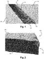
- microporous insulation blanket 100 (hereinafter microporous blanket or blanket 100).
- Blanket 100 consist of compressed fumed silica particles 106 and fibers 104 that are encased between two woven mat facers 102. Due to the nature of the microporous blanket 100, cutting the blanket by using a knife, scissors, water jet, and or lasers can sometimes lead to fall-out of the internal fumed silica 106 and/or other particles. For example, when the microporous blanket 100 is cut, a pair of exposed edges 108 are formed along the cut. Since the edge 108 is exposed, the internal fibers 104 may protrude or extend from the exposed edge 108. The fumed silica 106 and/or other particles may also fall-out or escape through the exposed edge 108, which reduces the amount of insulation material within the microporous blanket 100, especially along or near the exposed edge 108.
- the fall-out of the insulation material may be particular evident when a dull blade from a knife or scissors is used to cut the blanket.
- the dull blade may render the exposed edge 108 relatively roughly and/or may pull the fibers 104 and fumed silica 106 and/or other particles from within the interior of the blanket 100.
- a sharp knife is used with the proper technique (e.g., proper speed and angle)
- a cleaner edge 108 is formed with minimal disruption of the particles 106 and fibers 104.
- the result is a relatively clean edge 108 with minimal fall-out of the particles 106 and fibers 104.
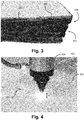
- microporous insulation blanket 200 (hereinafter microporous blanket or blanket 200) that includes insulation material particles (e.g., compressed fumed silica) and entangled nonwoven fibers (collectively 204) that are encased or positioned between two facers 202.
- the microporous blanket 200 is cut along at least one edge 208 and in many embodiment along at least two or more edges 208. The cut edges are exposed to the surrounding environment.
- insulation material particles e.g., compressed fumed silica
- entangled nonwoven fibers collectively 204
- the cut edges are exposed to the surrounding environment.
- a barrier 206 is formed on the face of the exposed edge(s) 208 to encase or seal the insulation material particles and nonwoven fibers 204 within the microporous blanket 200 - specifically, encase or seal the insulation material particles and nonwoven fibers 204 between the two opposing facers 202.
- the barrier 206 formed on the face of the exposed edge(s) 208 is a crust or cauterized edge that is formed using high temperatures that fuse the internal material of the microporous blanket 200.
- the high temperatures cause the insulation material particles and/or nonwoven fibers 204, and/or any other materials positioned within the blanket 200, to transition to a molten state.
- the molten insulation material particles and/or nonwoven fibers 204 than mix to some degree before the high temperatures are removed, which causes the molten insulation material particles and/or nonwoven fibers 204 to recrystallize and form the crust or cauterized edge on the face of the exposed edge 208.
- the recrystallized internal materials encase and seal the remaining internal materials within the blanket 200, which prevents or minimizes shedding or fall-out of the internal materials during handling and installation of the blanket about an object to be insulated.
- Encasing the internal material by forming barrier 206 is especially useful for industrial applications where the microporous blanket 200 is applied to elbows, fittings, and other specialized shapes.
- unique shapes for elbows and other objects can be quickly cut using a high temperature laser, thereby minimizing labor.
- the use of a high temperature laser simultaneously cauterizes the exposed edges 208 while the blanket 200 is cut to minimize fall-out or shedding of the insulation material particles and/or nonwoven fibers 204.
- the exposed edge 208 may be exposed to an open flame for a given amount of time to form the barrier 206.
- the exposed edge's face is cauterized to form a sufficient barrier 206. For example, in one embodiment greater than 50% of the face of the exposed edge 208 is cauterized. In another embodiment, greater than 70% of the exposed edge's face is cauterized. In yet other embodiments, greater than 80% or 90% of the exposed edge's face is cauterized. It is equally important to prevent or refrain from cauterizing all of the exposed edge's face to ensure that the exposed edge 208 does not become brittle and fracture or break during handling or installation as described above. As such, in some embodiments, less than or about 95% of the exposed edge's face is cauterized.
- Some blankets may require an upper cauterization limit of less than or about 90% or 85% of the exposed edge's face.
- the exposed edge may be cauterized by between 70% and 90% or 95%. In other embodiments, the exposed edge may be cauterized by between 80% and 90% or 95%.
- the face of the exposed edge 208 is heated to form a plurality of discontinuous cauterized portions or segments.
- the discontinuous cauterized portions or segments allow the barrier 206 to be formed without causing the exposed edge 208 to become brittle.
- the discontinuous cauterized portions or segments are able to move or shift slightly relative to one another without causing significant damage to adjacent cauterized portions or segments. This enables the exposed edge 208 to bend and flex without breaking or fracturing.
- discontinuous cauterized portions or segments are formed close enough together so that the discontinuous cauterized portions or segments function cooperatively or synergistically to encase and seal the internal material (e.g., insulation material particles and/or nonwoven fibers 204) within the interior of the microporous blanket 200.
- internal material e.g., insulation material particles and/or nonwoven fibers 20
- the face of the exposed edge 208 has a cauterization thickness T or depth of between about 0.05 mm and 3 mm. In other embodiments, the cauterization thickness T or depth may range between about 0.1 mm and 2 mm. This cauterization thickness T or depth forms a cauterization barrier 206 that is thick enough to withstand cracking or fracturing due to normal handling and installation of the blanket and is thick enough to hold, encase, or seal the internal material within the blanket 200. The cauterization thickness T or depth is also thin enough to form the discontinuous cauterized portions or segments described above.
- a cauterization thickness T or depth greater than 3 mm may be subject to cracking or fracturing of the formed barrier 206, which may cause cauterized segments to fall off or shed from the face of the exposed edge 208, thereby forming gaps or holes on the exposed edge's face through which the internal material may pass, shed, or otherwise be lost.
- a cauterization thickness T or depth of greater the 3 mm may also result in unnecessary labor times, thereby increasing the cost of installation of the blanket 200.
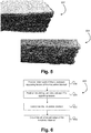
- the discontinuous cauterized portions or segments are formed via cutting of the exposed edge 302 with a high temperature laser.
- the high temperature laser cuts the exposed edge 302 in a manner that forms a layering pattern 306 on the face 304.
- the layered pattern 306 minimizes fall-out of the internal materials, which may be ideal for industrial fittings and specialized shapes.
- the layered pattern 306 also allows the blanket 300 and exposed edge 302 to maintaining flexibility so that the formed barrier is not substantially degraded due to handling and installation of the blanket 300.
- the layered pattern 306 of cauterized material is not uniform and does not entirely cover the face 304 of the exposed edge 302.
- the cauterized portions or segments are discontinuous with some cauterized portions or segments extending roughly horizontal and others extending at an angle or roughly vertical.
- This configuration allows the formed barrier to move or shift, or even break or fracture to some minor degree, while sufficient sealing or encasing the internal materials within the microporous blanket 300. Accordingly, the blanket 300 may be flexed, handled, and bent without a significant loss of the internal materials.
- the layered pattern 306 provides stress relief so that the entire cauterization barrier does not fall off when the blanket 300 is flexed, handled, and bent during installation or transportation.
- the layered pattern 306 has a cauterization coverage (i.e., amount of the face 304 that is cauterized) of greater than 80% and in many embodiments greater than 90%.
- the cauterization coverage of the layered patter 306 is also less than 100% and in many embodiments is less than 97% or 95%. This cauterization coverage minimizes fall-out or shedding of the internal materials (i.e., fumed silica and/or glass fibers) at the exposed edges 302 while preventing the face 304 and exposed edge 302 from being too brittle.
- the high temperature laser that is used to cut the exposed edge 302 and cauterize the face 304 should be controlled during the processing as described below to achieve a sufficient cauterization coverage of the face 304.
- the processing of the laser may be dependent on the internal microporous composition (e.g., fibers, particles, and the like.).
- the layered pattern 306 has a cauterization thickness or depth of between about 0.05 mm and 3 mm and in some embodiments between about 0.1 mm and 2 mm.
- This cauterization thickness or depth is not too thin, which could cause the formed cauterization barrier to easily crack and break and/or is not too thin to penetrate the face 304 enough to hold, seal, or encase the internal material within the microporous blanket 300.
- the cauterization thickness or depth is not too thick to cause the formed barrier to easily crack and/or flake off from the face 304 of the exposed edge 302 in relatively large pieces, which would form gaps or holes in the face 304 that allow the internal material to shed or be lost from within the microporous blanket 300.
- a process 400 of cutting an insulation blanket 402 with a high temperature laser 404 illustrated is a process 400 of cutting an insulation blanket 402 with a high temperature laser 404.
- the high temperature laser 404 is used to simultaneously cut 406 and cauterize the insulation blanket 402.
- one or more of the following parameters of the laser 404 need to be controlled: a distance H of laser nozzle to the blanket 402; the laser wattage; the type of laser tip; the speed of laser; and/or the density, compression, and/or hardness of the blanket.
- the focal length or distance H of the laser nozzle to the blanket 402 may be between about 2 and 7 inches, although a range of between about 2.5 and 5 inches is more common. A greater focal length is typically better for thicker blankets 402 due to deeper focal penetration, while a lesser focal length may be better for thinner blankets 402. A focal length of about 2.5 may be optimal for a 10 mm thick blanket 402.
- the laser power or wattage may be between about 150 W and 400 W. A higher power laser may be better due to the higher temperature.
- the laser or cutting speed normally needs to be associated with the laser power used.
- lower power laser typically require slower cutting speeds to achieve the sufficient heat to cauterize the exposed edge.
- the laser speed may be between about 0.01 inches per second (in/s) and 10 inches per second.
- Fig. 5 illustrates the improved cauterization that is achieved using a nitrogen purge gas in comparison with air or oxygen.
- blanket 502 was cauterized using a nitrogen purge gas while blanket 504 was cauterized using an oxygen purge gas.
- the laser parameters used to cauterize the two blankets were the same other than the purge gas.
- the cauterization coverage of blanket 502 is greater than blanket 504, which experienced a more flaky crust layer.
- a purge gas pressure of between about 15 psi and 40 psi has been shown to achieve an optimal cauterized face.
- a purge gas pressure of about 15 psi may be optimal for a 10 mm thick blanket 402.
- the laser power should be maintained at about 50% or greater. This ensures that the laser does not turn off when forming a corner. If the laser power goes below about 50%, a clean cut of the blanket 402 may not be obtained at the corner.
- a pulse rate of between about 500 pulse per inch and 3,000 pulse per inch may be used in forming the cauterized face. This may be achieved by using a pulse frequency of between about 500 to 50,000. In some embodiments, a pulse frequency of about 20,000 may be ideal.
- the cauterization process may be further improved by compressing the blanket 402 before cutting the blanket with the laser. Compressing the blanket 402 may improve the consistency or uniformity of the blanket's thickness and/or density, which improves cauterization of the material.
- a 10 mm thick insulation blanket i.e.,InsulThin HT
- a 10 mm thick insulation blanket i.e.,InsulThin HT
- a 400 W laser was used to cut the blanket.
- the cutting speed of the laser was approximately 1 inch per second and the focal length of the laser was approximately 2.5 inches.
- Nitrogen gas was used as the purge gas at a pressure of approximately 15 psi.
- the laser had a pulse frequency of approximately 20,000.
- a method 600 of forming an insulation blanket At block 610, a plurality of intermeshed non-woven fibers are positioned between a first facer layer and a second facer layer.
- the intermeshed non-woven fibers include glass fibers.
- a fine insulating powder or particles are positioned between the first and second facer layers and within the intermeshed non-woven fibers.
- the fine insulating powder or particles typically have an average particle size of between about 2 and 300 nanometers.
- the fine insulating powder or particles may include fumed silica.
- the non-woven fibers and the fine insulating powder or particles are mixed prior to positioning the fibers and particles between the first facer layer and the second facer layer.
- the insulation blanket may optionally be compressed. Compressing the insulation blanket may improve the cauterization process by rendering the blanket's thickness and/or density more consistent and/or uniform. In other embodiments, the insulation blanket may not be compressed and block 630 may not be performed.
- an exposed edge of the insulation blanket is cauterized to form a barrier on the exposed edge that encases or seals the fine insulating powder or particles within the interior of the insulation blanket.
- the cauterized edge may have a depth of cauterized material of between about 0.05 mm and 3 mm, and in some embodiments between about 0.1 mm and 2 mm.
- cauterizing the exposed edge may include forming a plurality of cauterized layers on a face of the exposed edge.
- Cauterizing the face of the exposed edge may include cauterizing at least 80% of the exposed edge without cauterizing the entire exposed edge and/or may include cauterizing at least 90% of the exposed edge without cauterizing the entire exposed edge.
- the cauterization process of block 640 may involve simultaneously cutting the insulation blanket to form the exposed edge.
- the process of block 640 may be performed with a high temperature laser.
- the process of block 640 may be performed by exposing the exposed edge of the insulation blanket to a flame.
- the method 600 may also include installing the insulation blanket on or about an object to be insulated.
- the R-value is measured according to ASTM C518-15, Standard Test Method for Steady-State Thermal Transmission Properties by Means of the Heat Flow Meter Apparatus, ASTM International, West Conshohocken, PA, 2015, www.astm.org
- the depth of the cauterized edge is measured by optical inspection, including microscopic methods.
- the degree of cauterization given in % refer to the total surface of the edge (side surface) being cauterized is determined by optical methods.
- the total surface of the respective edge amounts to 100% and the surface area being cauterized is given in % of the total surface of the respective edge. Due to openings/pockets caused by the intermeshed non-woven fibers the degree of cauterization given in % (surface) is ⁇ 100%.
- the preferred optical method is taking pictures, such as digital pictures, and determining the respective areas by suitable methods, such as digital methods.
- the average particle size is determined according to DIN ISO 13320-1 (2009-10-01).
- a suitable system for measuring the average particle is e.g. the Microtrac S 3500 apparatus.
Landscapes
- Engineering & Computer Science (AREA)
- General Engineering & Computer Science (AREA)
- Mechanical Engineering (AREA)
- Life Sciences & Earth Sciences (AREA)
- Wood Science & Technology (AREA)
- Thermal Insulation (AREA)
Claims (22)
- Wärmedämmdecke zur Isolierung einer Struktur umfassend(i) eine erste Facerschicht,(i) eine zweite Facerschicht,(iii) eine Vielzahl von vermaschten Vliesstofffasern zwischen der ersten und der zweiten Schicht, und(iv) ein zwischen der ersten und der zweiten Facerschicht und innerhalb der vermaschten Vliesstofffasern befindliches Isolierpulver,wobei die Wärmedämmdecke mindestens einen freiliegenden Rand mit einer kauterisierten Stirnfläche beinhaltet, die ungefähr orthogonal zu der ersten und zweiten Facerschicht verläuft, wobei die kauterisierte Stirnfläche eine Barriere auf dem freiliegenden Rand bildet, die das Isolierpulver im Innern der Wärmedämmdecke einschließt und auf diese Weise eine Verschlechterung des Isolierwerts durch den Verlust oder das Ablösen von Isolierpulver durch den freiliegenden Rand hindurch auf ein Mindestmaß reduziert, wobei der kauterisierte Rand eine Tiefe an kauterisiertem Material von zwischen 0,05 und 3 mm aufweist.
- Wärmedämmdecke nach Anspruch 1, wobei es sich bei den zwischen der ersten und der zweiten Facerschicht befindlichen Vliesstofffasern um organische Polymerfasern und/oder anorganische Fasern handelt, bei den organischen Polymerfasern vorzugsweise um schmelzverspinnbare synthetische Polymerfasern handelt, bei den anorganischen Fasern vorzugsweise um Mineralfasern, Glasfasern oder Mischungen derselben handelt.
- Wärmedämmdecke nach Anspruch 1 oder 2, wobei es sich bei dem zwischen der ersten und zweiten Facerschicht und innerhalb der vermaschten Vliesstofffasern befindlichen Isolierpulver um ein anorganisches Isolierpulver, vorzugsweise um ein pyrogenes Siliciumoxid, handelt.
- Wärmedämmdecke nach einem oder mehreren der Ansprüche 1 bis 3, wobei mindestens 80% der freiliegenden Kante kauterisiert sind, vorzugsweise mindestens 90%, aber weniger als die gesamte freiliegende Kante kauterisiert sind.
- Wärmedämmdecke nach einem oder mehreren der Ansprüche 1 bis 4, wobei die kauterisierte Stirnfläche eine Vielzahl von kauterisierten Schichten zwischen dem ersten und zweiten Facer bildet.
- Wärmedämmdecke nach einem oder mehreren der Ansprüche 1 bis 5, wobei es sich bei entweder dem ersten oder dem zweiten Facer oder bei beiden um einen gewebten Glasfasermatten-Facer handelt.
- Wärmedämmdecke nach einem oder mehreren der Ansprüche 1 bis 6, wobei die Wärmedämmdecke eine Vielzahl von freiliegenden Kanten beinhaltet und wobei jede freiliegende Kante eine kauterisierte Stirnfläche aufweist, die eine Barriere bildet, die das Isolierpulver im Inneren der Wärmedämmdecke einschließt.
- Wärmedämmdecke nach einem oder mehreren der Ansprüche 1 bis 7, wobei die freiliegende Kante eine Tiefe an kauterisiertem Material von zwischen 0,05 und 3 mm aufweist.
- Wärmedämmdecke nach einem oder mehreren der Ansprüche 1 bis 7, wobei es sich bei dem zwischen der ersten und zweiten Facerschicht und innerhalb der vermaschten Vliesstofffasern befindlichen Isolierpulver um ein anorganisches Isolierpulver handelt, vorzugsweise um ein pyrogenes Siliciumoxid mit einer durchschnittlichen Teilchengröße zwischen 2 und 5000 Nanometern, vorzugsweise zwischen 2 und 300 Nanometern, bevorzugter zwischen 2 und 20 Nanometern.
- Verfahren zur Bildung einer Wärmedämmdecke, umfassend:(i) Aufbringen einer Vielzahl von vermaschten Vliesstoffasern zwischen einer ersten Facerschicht und einer zweiten Facerschicht,(ii) Aufbringen eines Isolierpulvers zwischen der ersten und der zweiten Facerschicht und innerhalb der vermaschten Vliesstofffasern, und(iii) Kauterisieren eines freiliegenden Randes der Wärmedämmdecke zur Bildung einer Barriere auf der freiliegenden Kante, die das Isolierpulver im Inneren der Wärmedämmdecke einschließt.
- Verfahren nach Anspruch 10, wobei die kauterisierte Kante eine Tiefe an kauterisiertem Material von zwischen 0,05 und 3 mm aufweist.
- Verfahren nach Anspruch 10 oder 11, wobei es sich bei den zwischen der ersten und der zweiten Facerschicht befindlichen Vliesstofffasern um organische Polymerfasern und/oder anorganische Fasern handelt, bei den organischen Polymerfasern vorzugsweise um schmelzverspinnbare synthetische Polymerfasern handelt, bei den anorganischen Fasern vorzugsweise um Mineralfasern, Glasfasern oder Mischungen derselben handelt.
- Verfahren nach einem oder mehreren der Ansprüche 10 bis 12, wobei es sich bei dem zwischen der ersten und zweiten Facerschicht und innerhalb der vermaschten Vliesstofffasern befindlichen Isolierpulver um ein anorganisches Isolierpulver, vorzugsweise ein pyrogenes Siliciumoxid, handelt.
- Verfahren nach einem oder mehreren der Ansprüche 10 bis 13, wobei mindestens 80% der freiliegenden Kante kauterisiert sind, vorzugsweise mindestens 90%, aber weniger als die gesamte freiliegende Kante kauterisiert sind.
- Verfahren nach einem oder mehreren der Ansprüche 10 bis 14, wobei die kauterisierte Stirnfläche eine Vielzahl von kauterisierten Schichten zwischen dem ersten und zweiten Facer bildet.
- Verfahren nach einem oder mehreren der Ansprüche 10 bis 15, wobei es sich bei entweder dem ersten oder dem zweiten Facer oder bei beiden um einen gewebten Glasfasermatten-Facer handelt.
- Verfahren nach einem oder mehreren der Ansprüche 10 bis 16, wobei es sich bei dem zwischen der ersten und zweiten Facerschicht und innerhalb der vermaschten Vliesstofffasern befindlichen Isolierpulver um ein anorganisches Isolierpulver handelt, vorzugsweise um ein pyrogenes Siliciumoxid mit einer durchschnittlichen Teilchengröße zwischen 2 und 5000 Nanometern, vorzugsweise zwischen 2 und 300 Nanometern, bevorzugter zwischen 2 und 20 Nanometern.
- Verfahren nach einem oder mehreren der Ansprüche 10 bis 17, darüber hinaus umfassend das Schneiden der Decke zur Bildung des freiliegenden Randes und gleichzeitiges Kauterisieren des freiliegenden Randes.
- Verfahren nach einem oder mehreren der Ansprüche 10 bis 18, wobei das Kauterisieren des freiliegenden Randes der Wärmedämmdecke das Schneiden der Wärmedämmdecke mit einem Hochtemperaturlaser umfasst.
- Verfahren nach einem oder mehreren der Ansprüche 10 bis 18, wobei das Kauterisieren des freiliegenden Randes der Wärmedämmdecke das Inkontaktbringen des freiliegenden Randes der Wärmedämmdecke mit einer Flamme umfasst.
- Verfahren nach einem oder mehreren der Ansprüche 10 bis 20, darüber hinaus das Komprimieren der Wärmedämmdecke vor der Kauterisierung des freiliegenden Randes umfassend.
- Verfahren nach einem oder mehreren der Ansprüche 10 bis 21, darüber hinaus das Anbringen der Wärmedämmdecke an oder um einen zu isolierenden Gegenstand herum umfassend.
Applications Claiming Priority (1)
| Application Number | Priority Date | Filing Date | Title |
|---|---|---|---|
| US14/642,492 US10234069B2 (en) | 2015-03-09 | 2015-03-09 | High temperature flexible blanket for industrial insulation applications |
Publications (2)
| Publication Number | Publication Date |
|---|---|
| EP3067201A1 EP3067201A1 (de) | 2016-09-14 |
| EP3067201B1 true EP3067201B1 (de) | 2019-05-08 |
Family
ID=55699327
Family Applications (1)
| Application Number | Title | Priority Date | Filing Date |
|---|---|---|---|
| EP16158374.5A Active EP3067201B1 (de) | 2015-03-09 | 2016-03-03 | Flexible hochtemperaturdecke für industrielle isolierungsanwendungen |
Country Status (2)
| Country | Link |
|---|---|
| US (2) | US10234069B2 (de) |
| EP (1) | EP3067201B1 (de) |
Families Citing this family (2)
| Publication number | Priority date | Publication date | Assignee | Title |
|---|---|---|---|---|
| US10234069B2 (en) | 2015-03-09 | 2019-03-19 | Johns Manville | High temperature flexible blanket for industrial insulation applications |
| US11187367B2 (en) * | 2019-05-07 | 2021-11-30 | Johns Manville | Insulation blanket having a deposited passivator for industrial insulation applications |
Citations (11)
| Publication number | Priority date | Publication date | Assignee | Title |
|---|---|---|---|---|
| US4365135A (en) | 1979-12-14 | 1982-12-21 | Micropore International Ltd. | Shaping of thermal insulation material |
| NL8303106A (nl) | 1983-09-07 | 1985-04-01 | Rigips Benelux V O F | Isolatieproduct en werkwijze voor het isoleren van een constructie. |
| US4564547A (en) | 1983-08-04 | 1986-01-14 | Micropore International Limited | Handleable shapes of thermal insulation material |
| EP0790366B1 (de) | 1996-02-13 | 1998-07-15 | Micropore International Limited | Flexibles Wärmedämmpaneel und Verfahren zur Herstellung |
| EP0714754B1 (de) | 1994-12-02 | 2001-01-31 | Owens Corning | Verfahren zum Herstellen eines Isolieraufbaus |
| AU4384501A (en) | 2000-06-14 | 2001-12-20 | Esab Group, Inc., The | Cutting apparatus with thermal and nonthermal cutters, and associated methods |
| US20030060107A1 (en) | 2001-09-21 | 2003-03-27 | Gooliak Robert M. | Thermal blanket including a radiation layer |
| US6936326B1 (en) | 1998-12-19 | 2005-08-30 | Promat International N.V. | Microporous heat insulating body |
| US20060125158A1 (en) | 2004-12-15 | 2006-06-15 | Rouanet Stephane F | Aerogel containing blanket |
| US20080166937A1 (en) | 2007-01-08 | 2008-07-10 | Unifrax I Llc | Fire-barrier film laminate |
| WO2011133778A2 (en) | 2010-04-23 | 2011-10-27 | Unifrax I Llc | Multi-layer thermal insulation composite |
Family Cites Families (4)
| Publication number | Priority date | Publication date | Assignee | Title |
|---|---|---|---|---|
| US5208440A (en) * | 1991-09-12 | 1993-05-04 | Conley James A | Plasma arc cutting of conductive and non-conductive materials |
| CN102783740B (zh) * | 2012-08-16 | 2014-04-23 | 东华大学 | 一种多层反射与相变功能的防火绝热复合织物及用途 |
| WO2014150310A1 (en) * | 2013-03-15 | 2014-09-25 | Cabot Corporation | Aerogel blanket and method of production |
| US10234069B2 (en) | 2015-03-09 | 2019-03-19 | Johns Manville | High temperature flexible blanket for industrial insulation applications |
-
2015
- 2015-03-09 US US14/642,492 patent/US10234069B2/en active Active
-
2016
- 2016-03-03 EP EP16158374.5A patent/EP3067201B1/de active Active
-
2019
- 2019-01-28 US US16/259,821 patent/US11815217B2/en active Active
Patent Citations (11)
| Publication number | Priority date | Publication date | Assignee | Title |
|---|---|---|---|---|
| US4365135A (en) | 1979-12-14 | 1982-12-21 | Micropore International Ltd. | Shaping of thermal insulation material |
| US4564547A (en) | 1983-08-04 | 1986-01-14 | Micropore International Limited | Handleable shapes of thermal insulation material |
| NL8303106A (nl) | 1983-09-07 | 1985-04-01 | Rigips Benelux V O F | Isolatieproduct en werkwijze voor het isoleren van een constructie. |
| EP0714754B1 (de) | 1994-12-02 | 2001-01-31 | Owens Corning | Verfahren zum Herstellen eines Isolieraufbaus |
| EP0790366B1 (de) | 1996-02-13 | 1998-07-15 | Micropore International Limited | Flexibles Wärmedämmpaneel und Verfahren zur Herstellung |
| US6936326B1 (en) | 1998-12-19 | 2005-08-30 | Promat International N.V. | Microporous heat insulating body |
| AU4384501A (en) | 2000-06-14 | 2001-12-20 | Esab Group, Inc., The | Cutting apparatus with thermal and nonthermal cutters, and associated methods |
| US20030060107A1 (en) | 2001-09-21 | 2003-03-27 | Gooliak Robert M. | Thermal blanket including a radiation layer |
| US20060125158A1 (en) | 2004-12-15 | 2006-06-15 | Rouanet Stephane F | Aerogel containing blanket |
| US20080166937A1 (en) | 2007-01-08 | 2008-07-10 | Unifrax I Llc | Fire-barrier film laminate |
| WO2011133778A2 (en) | 2010-04-23 | 2011-10-27 | Unifrax I Llc | Multi-layer thermal insulation composite |
Non-Patent Citations (23)
| Title |
|---|
| "Blanket", XP055683779, Retrieved from the Internet <URL:https://www.lexico.com/definition/blanket> [retrieved on 20200117] |
| "Blanket", XP055683784, Retrieved from the Internet <URL:https://www.merriam-webster.com/dictionary/blanket> [retrieved on 20200127] |
| "Excelflex® Microporous insulation", THERMODYNE, 1 July 2001 (2001-07-01), XP055683581 |
| "FeatherflexTM Microporous insulation", THERMODYNE, 20 December 2005 (2005-12-20), XP055683589 |
| "High temperature microporous insulation", PROMAT, May 2014 (2014-05-01), pages 1 - 69, XP055683770 |
| "Insulthin® HT Hydrophobic Microporous Thin Blanket Insulation Data Sheet", JOHN MANVILLE, 18 February 2019 (2019-02-18), XP055683593 |
| "InsulThinTM HT Safety Data Sheet 200000001774", JOHNS MANVILLE, 2 May 2016 (2016-05-02), pages 1 - 9, XP055683602 |
| "Microtherm Grades - Standard, Hydrophobic", MSDS MICROTHERM SILICA BASED THERMAL INSULATION PRODUCTS - STANDARD GRADES, 16 February 2000 (2000-02-16), XP055683757 |
| "Microtherm Insulation Product and Performance Data", 29 May 2001 (2001-05-29), XP055683633 |
| "Microtherm Insulation Use in Power Generation", 3 March 1997 (1997-03-03), XP055683637 |
| "Microtherm Panel", September 1990 (1990-09-01), pages 1 - 12, XP055683629 |
| "Microtherm Product Performance", 31 January 2011 (2011-01-31), XP055683653 |
| "Microtherm(R) Insulation for Fuel Cell Applications", MICROTHERM, 30 April 2009 (2009-04-30), XP055683766 |
| "Microtherm? Grades - G, Super G, Super G Hydrophobic", MSDS MICROTHERM SILICA BASED THERMAL INSULATION PRODUCTS, 5 January 2000 (2000-01-05), XP055683764 |
| "Ullman's Encyclopedia of Industrial Chemistry", 2007, article "Silica", pages: 1 - 89, XP055683575 |
| IIG EDITORS: "Need Insulation For Tight Spaces? Now There's IIG's InsulThinTM HT", 20 May 2014 (2014-05-20), XP055683610 |
| MICROTHERM INSULATION PANEL |
| MICROTHERM INSULATION THE WORLD'S BEST HIGH TEMPERATURE THERMAL INSULATION FOR FUEL CELLS, 7 May 2002 (2002-05-07), XP055683657 |
| OEM INSULATION - INSULTHIN® HT DATA SHEET |
| TECHNICAL DRAWING MICROTHERM, 12 August 2004 (2004-08-12) |
| TECHNICAL DRAWING MICROTHERM, 18 July 2014 (2014-07-18) |
| WAYBACK MACHINE CAPTURE OF THE WIKIPEDIA PAGE ''AEROGEL |
| WAYBACK MACHINE CAPTURE OF THE WIKIPEDIA PAGE ''FUMED SILICA |
Also Published As
| Publication number | Publication date |
|---|---|
| US11815217B2 (en) | 2023-11-14 |
| US20160265709A1 (en) | 2016-09-15 |
| US20190154187A1 (en) | 2019-05-23 |
| US10234069B2 (en) | 2019-03-19 |
| EP3067201A1 (de) | 2016-09-14 |
Similar Documents
| Publication | Publication Date | Title |
|---|---|---|
| EP3847715B1 (de) | Feuerschutzartikel und zugehörige verfahren | |
| EP2780162B1 (de) | Feuerhemmende schicht und feuerhemmendes filmlaminat | |
| HRP20160383T1 (hr) | Elastomerna izolacija zaštićena od vatre | |
| EP1609158A1 (de) | Kabel und artikelentwurf für feuerleistungsfähigkeit | |
| EP3067201B1 (de) | Flexible hochtemperaturdecke für industrielle isolierungsanwendungen | |
| AU2019212006B2 (en) | Assembly comprising a plurality of fire protection profiles and method for producing a fire protection profile | |
| JP5842950B2 (ja) | 熱膨張性耐火樹脂組成物およびその形成体の製造方法。 | |
| EP3260290A1 (de) | Thermisch isolierende decken | |
| KR101558953B1 (ko) | 단열성이 개선된 반사형 단열재 | |
| KR102495183B1 (ko) | 건축용 단열재의 면재 | |
| CN102095048A (zh) | 一种开孔的玻璃纤维真空绝热板及其制作方法 | |
| EP2818784A1 (de) | Schalldämpfende wärmedämmende mattenanordnung und montageverfahren für schalldämpfende wärmedämmende mattenanordnung | |
| EP2993278A1 (de) | Zusammengesetztes feuersicheres trennelement | |
| FI3799935T3 (fi) | Eristekalvon muodostava tulenestopinnoite | |
| JP2008031799A (ja) | 防火区画貫通部の施工方法及び防火区画貫通部構造 | |
| KR102142863B1 (ko) | 건축용 패널 및 이의 제조방법 | |
| JPWO2016157931A1 (ja) | 真空断熱材用外包材、真空断熱材、および真空断熱材付き機器 | |
| JP2016151125A (ja) | 防火サッシの膨張材貼りつけ方法、およびその方法によって製造された防火サッシ | |
| KR102809461B1 (ko) | 건축용 단열재의 면재 및 이의 제조방법 | |
| JP2008031798A (ja) | 免震構造物 | |
| KR102276662B1 (ko) | 중공 구조를 가지는 플라스틱 시트의 금형 조립체 | |
| EP1895224A1 (de) | Rohrabschnitt versehen mit einem rohrförmigen Isolationselement aus einem Feuer verhinderndem Material | |
| JP2008031800A (ja) | ダクト | |
| JP7168433B2 (ja) | 耐火シート及びその巻回体 | |
| JP4394587B2 (ja) | 熱膨張性無機質材料 |
Legal Events
| Date | Code | Title | Description |
|---|---|---|---|
| PUAI | Public reference made under article 153(3) epc to a published international application that has entered the european phase |
Free format text: ORIGINAL CODE: 0009012 |
|
| AK | Designated contracting states |
Kind code of ref document: A1 Designated state(s): AL AT BE BG CH CY CZ DE DK EE ES FI FR GB GR HR HU IE IS IT LI LT LU LV MC MK MT NL NO PL PT RO RS SE SI SK SM TR |
|
| AX | Request for extension of the european patent |
Extension state: BA ME |
|
| STAA | Information on the status of an ep patent application or granted ep patent |
Free format text: STATUS: REQUEST FOR EXAMINATION WAS MADE |
|
| 17P | Request for examination filed |
Effective date: 20170227 |
|
| RBV | Designated contracting states (corrected) |
Designated state(s): AL AT BE BG CH CY CZ DE DK EE ES FI FR GB GR HR HU IE IS IT LI LT LU LV MC MK MT NL NO PL PT RO RS SE SI SK SM TR |
|
| STAA | Information on the status of an ep patent application or granted ep patent |
Free format text: STATUS: EXAMINATION IS IN PROGRESS |
|
| 17Q | First examination report despatched |
Effective date: 20170511 |
|
| GRAP | Despatch of communication of intention to grant a patent |
Free format text: ORIGINAL CODE: EPIDOSNIGR1 |
|
| STAA | Information on the status of an ep patent application or granted ep patent |
Free format text: STATUS: GRANT OF PATENT IS INTENDED |
|
| INTG | Intention to grant announced |
Effective date: 20181122 |
|
| GRAS | Grant fee paid |
Free format text: ORIGINAL CODE: EPIDOSNIGR3 |
|
| GRAA | (expected) grant |
Free format text: ORIGINAL CODE: 0009210 |
|
| STAA | Information on the status of an ep patent application or granted ep patent |
Free format text: STATUS: THE PATENT HAS BEEN GRANTED |
|
| AK | Designated contracting states |
Kind code of ref document: B1 Designated state(s): AL AT BE BG CH CY CZ DE DK EE ES FI FR GB GR HR HU IE IS IT LI LT LU LV MC MK MT NL NO PL PT RO RS SE SI SK SM TR |
|
| REG | Reference to a national code |
Ref country code: GB Ref legal event code: FG4D |
|
| REG | Reference to a national code |
Ref country code: CH Ref legal event code: EP Ref country code: AT Ref legal event code: REF Ref document number: 1129526 Country of ref document: AT Kind code of ref document: T Effective date: 20190515 |
|
| REG | Reference to a national code |
Ref country code: DE Ref legal event code: R096 Ref document number: 602016013423 Country of ref document: DE Ref country code: IE Ref legal event code: FG4D |
|
| REG | Reference to a national code |
Ref country code: NL Ref legal event code: MP Effective date: 20190508 |
|
| REG | Reference to a national code |
Ref country code: LT Ref legal event code: MG4D |
|
| PG25 | Lapsed in a contracting state [announced via postgrant information from national office to epo] |
Ref country code: AL Free format text: LAPSE BECAUSE OF FAILURE TO SUBMIT A TRANSLATION OF THE DESCRIPTION OR TO PAY THE FEE WITHIN THE PRESCRIBED TIME-LIMIT Effective date: 20190508 Ref country code: PT Free format text: LAPSE BECAUSE OF FAILURE TO SUBMIT A TRANSLATION OF THE DESCRIPTION OR TO PAY THE FEE WITHIN THE PRESCRIBED TIME-LIMIT Effective date: 20190908 Ref country code: ES Free format text: LAPSE BECAUSE OF FAILURE TO SUBMIT A TRANSLATION OF THE DESCRIPTION OR TO PAY THE FEE WITHIN THE PRESCRIBED TIME-LIMIT Effective date: 20190508 Ref country code: SE Free format text: LAPSE BECAUSE OF FAILURE TO SUBMIT A TRANSLATION OF THE DESCRIPTION OR TO PAY THE FEE WITHIN THE PRESCRIBED TIME-LIMIT Effective date: 20190508 Ref country code: HR Free format text: LAPSE BECAUSE OF FAILURE TO SUBMIT A TRANSLATION OF THE DESCRIPTION OR TO PAY THE FEE WITHIN THE PRESCRIBED TIME-LIMIT Effective date: 20190508 Ref country code: NO Free format text: LAPSE BECAUSE OF FAILURE TO SUBMIT A TRANSLATION OF THE DESCRIPTION OR TO PAY THE FEE WITHIN THE PRESCRIBED TIME-LIMIT Effective date: 20190808 Ref country code: LT Free format text: LAPSE BECAUSE OF FAILURE TO SUBMIT A TRANSLATION OF THE DESCRIPTION OR TO PAY THE FEE WITHIN THE PRESCRIBED TIME-LIMIT Effective date: 20190508 Ref country code: FI Free format text: LAPSE BECAUSE OF FAILURE TO SUBMIT A TRANSLATION OF THE DESCRIPTION OR TO PAY THE FEE WITHIN THE PRESCRIBED TIME-LIMIT Effective date: 20190508 Ref country code: NL Free format text: LAPSE BECAUSE OF FAILURE TO SUBMIT A TRANSLATION OF THE DESCRIPTION OR TO PAY THE FEE WITHIN THE PRESCRIBED TIME-LIMIT Effective date: 20190508 |
|
| PG25 | Lapsed in a contracting state [announced via postgrant information from national office to epo] |
Ref country code: RS Free format text: LAPSE BECAUSE OF FAILURE TO SUBMIT A TRANSLATION OF THE DESCRIPTION OR TO PAY THE FEE WITHIN THE PRESCRIBED TIME-LIMIT Effective date: 20190508 Ref country code: LV Free format text: LAPSE BECAUSE OF FAILURE TO SUBMIT A TRANSLATION OF THE DESCRIPTION OR TO PAY THE FEE WITHIN THE PRESCRIBED TIME-LIMIT Effective date: 20190508 Ref country code: BG Free format text: LAPSE BECAUSE OF FAILURE TO SUBMIT A TRANSLATION OF THE DESCRIPTION OR TO PAY THE FEE WITHIN THE PRESCRIBED TIME-LIMIT Effective date: 20190808 Ref country code: GR Free format text: LAPSE BECAUSE OF FAILURE TO SUBMIT A TRANSLATION OF THE DESCRIPTION OR TO PAY THE FEE WITHIN THE PRESCRIBED TIME-LIMIT Effective date: 20190809 |
|
| REG | Reference to a national code |
Ref country code: AT Ref legal event code: MK05 Ref document number: 1129526 Country of ref document: AT Kind code of ref document: T Effective date: 20190508 |
|
| PG25 | Lapsed in a contracting state [announced via postgrant information from national office to epo] |
Ref country code: AT Free format text: LAPSE BECAUSE OF FAILURE TO SUBMIT A TRANSLATION OF THE DESCRIPTION OR TO PAY THE FEE WITHIN THE PRESCRIBED TIME-LIMIT Effective date: 20190508 Ref country code: DK Free format text: LAPSE BECAUSE OF FAILURE TO SUBMIT A TRANSLATION OF THE DESCRIPTION OR TO PAY THE FEE WITHIN THE PRESCRIBED TIME-LIMIT Effective date: 20190508 Ref country code: SK Free format text: LAPSE BECAUSE OF FAILURE TO SUBMIT A TRANSLATION OF THE DESCRIPTION OR TO PAY THE FEE WITHIN THE PRESCRIBED TIME-LIMIT Effective date: 20190508 Ref country code: EE Free format text: LAPSE BECAUSE OF FAILURE TO SUBMIT A TRANSLATION OF THE DESCRIPTION OR TO PAY THE FEE WITHIN THE PRESCRIBED TIME-LIMIT Effective date: 20190508 Ref country code: RO Free format text: LAPSE BECAUSE OF FAILURE TO SUBMIT A TRANSLATION OF THE DESCRIPTION OR TO PAY THE FEE WITHIN THE PRESCRIBED TIME-LIMIT Effective date: 20190508 Ref country code: CZ Free format text: LAPSE BECAUSE OF FAILURE TO SUBMIT A TRANSLATION OF THE DESCRIPTION OR TO PAY THE FEE WITHIN THE PRESCRIBED TIME-LIMIT Effective date: 20190508 |
|
| REG | Reference to a national code |
Ref country code: DE Ref legal event code: R026 Ref document number: 602016013423 Country of ref document: DE |
|
| PLBI | Opposition filed |
Free format text: ORIGINAL CODE: 0009260 |
|
| PLAX | Notice of opposition and request to file observation + time limit sent |
Free format text: ORIGINAL CODE: EPIDOSNOBS2 |
|
| PG25 | Lapsed in a contracting state [announced via postgrant information from national office to epo] |
Ref country code: SM Free format text: LAPSE BECAUSE OF FAILURE TO SUBMIT A TRANSLATION OF THE DESCRIPTION OR TO PAY THE FEE WITHIN THE PRESCRIBED TIME-LIMIT Effective date: 20190508 |
|
| 26 | Opposition filed |
Opponent name: MICROTHERM NV Effective date: 20200207 |
|
| REG | Reference to a national code |
Ref country code: DE Ref legal event code: R082 Ref document number: 602016013423 Country of ref document: DE |
|
| PG25 | Lapsed in a contracting state [announced via postgrant information from national office to epo] |
Ref country code: TR Free format text: LAPSE BECAUSE OF FAILURE TO SUBMIT A TRANSLATION OF THE DESCRIPTION OR TO PAY THE FEE WITHIN THE PRESCRIBED TIME-LIMIT Effective date: 20190508 |
|
| PG25 | Lapsed in a contracting state [announced via postgrant information from national office to epo] |
Ref country code: PL Free format text: LAPSE BECAUSE OF FAILURE TO SUBMIT A TRANSLATION OF THE DESCRIPTION OR TO PAY THE FEE WITHIN THE PRESCRIBED TIME-LIMIT Effective date: 20190508 |
|
| PG25 | Lapsed in a contracting state [announced via postgrant information from national office to epo] |
Ref country code: SI Free format text: LAPSE BECAUSE OF FAILURE TO SUBMIT A TRANSLATION OF THE DESCRIPTION OR TO PAY THE FEE WITHIN THE PRESCRIBED TIME-LIMIT Effective date: 20190508 |
|
| PLBB | Reply of patent proprietor to notice(s) of opposition received |
Free format text: ORIGINAL CODE: EPIDOSNOBS3 |
|
| PG25 | Lapsed in a contracting state [announced via postgrant information from national office to epo] |
Ref country code: MC Free format text: LAPSE BECAUSE OF FAILURE TO SUBMIT A TRANSLATION OF THE DESCRIPTION OR TO PAY THE FEE WITHIN THE PRESCRIBED TIME-LIMIT Effective date: 20190508 |
|
| REG | Reference to a national code |
Ref country code: CH Ref legal event code: PL |
|
| PG25 | Lapsed in a contracting state [announced via postgrant information from national office to epo] |
Ref country code: LU Free format text: LAPSE BECAUSE OF NON-PAYMENT OF DUE FEES Effective date: 20200303 |
|
| PG25 | Lapsed in a contracting state [announced via postgrant information from national office to epo] |
Ref country code: CH Free format text: LAPSE BECAUSE OF NON-PAYMENT OF DUE FEES Effective date: 20200331 Ref country code: LI Free format text: LAPSE BECAUSE OF NON-PAYMENT OF DUE FEES Effective date: 20200331 Ref country code: IE Free format text: LAPSE BECAUSE OF NON-PAYMENT OF DUE FEES Effective date: 20200303 |
|
| PLCK | Communication despatched that opposition was rejected |
Free format text: ORIGINAL CODE: EPIDOSNREJ1 |
|
| APBM | Appeal reference recorded |
Free format text: ORIGINAL CODE: EPIDOSNREFNO |
|
| APBP | Date of receipt of notice of appeal recorded |
Free format text: ORIGINAL CODE: EPIDOSNNOA2O |
|
| PG25 | Lapsed in a contracting state [announced via postgrant information from national office to epo] |
Ref country code: MT Free format text: LAPSE BECAUSE OF FAILURE TO SUBMIT A TRANSLATION OF THE DESCRIPTION OR TO PAY THE FEE WITHIN THE PRESCRIBED TIME-LIMIT Effective date: 20190508 Ref country code: CY Free format text: LAPSE BECAUSE OF FAILURE TO SUBMIT A TRANSLATION OF THE DESCRIPTION OR TO PAY THE FEE WITHIN THE PRESCRIBED TIME-LIMIT Effective date: 20190508 |
|
| APAH | Appeal reference modified |
Free format text: ORIGINAL CODE: EPIDOSCREFNO |
|
| PG25 | Lapsed in a contracting state [announced via postgrant information from national office to epo] |
Ref country code: MK Free format text: LAPSE BECAUSE OF FAILURE TO SUBMIT A TRANSLATION OF THE DESCRIPTION OR TO PAY THE FEE WITHIN THE PRESCRIBED TIME-LIMIT Effective date: 20190508 Ref country code: IS Free format text: LAPSE BECAUSE OF FAILURE TO SUBMIT A TRANSLATION OF THE DESCRIPTION OR TO PAY THE FEE WITHIN THE PRESCRIBED TIME-LIMIT Effective date: 20190908 |
|
| APBQ | Date of receipt of statement of grounds of appeal recorded |
Free format text: ORIGINAL CODE: EPIDOSNNOA3O |
|
| APAH | Appeal reference modified |
Free format text: ORIGINAL CODE: EPIDOSCREFNO |
|
| APBU | Appeal procedure closed |
Free format text: ORIGINAL CODE: EPIDOSNNOA9O |
|
| REG | Reference to a national code |
Ref country code: DE Ref legal event code: R100 Ref document number: 602016013423 Country of ref document: DE |
|
| PLBN | Opposition rejected |
Free format text: ORIGINAL CODE: 0009273 |
|
| STAA | Information on the status of an ep patent application or granted ep patent |
Free format text: STATUS: OPPOSITION REJECTED |
|
| 27O | Opposition rejected |
Effective date: 20241022 |
|
| PGFP | Annual fee paid to national office [announced via postgrant information from national office to epo] |
Ref country code: GB Payment date: 20260327 Year of fee payment: 11 |
|
| PGFP | Annual fee paid to national office [announced via postgrant information from national office to epo] |
Ref country code: DE Payment date: 20260327 Year of fee payment: 11 |
|
| PGFP | Annual fee paid to national office [announced via postgrant information from national office to epo] |
Ref country code: BE Payment date: 20260327 Year of fee payment: 11 Ref country code: IT Payment date: 20260319 Year of fee payment: 11 |
|
| PGFP | Annual fee paid to national office [announced via postgrant information from national office to epo] |
Ref country code: FR Payment date: 20260325 Year of fee payment: 11 |