EP3067213A1 - Tampon encreur - Google Patents
Tampon encreur Download PDFInfo
- Publication number
- EP3067213A1 EP3067213A1 EP16164808.4A EP16164808A EP3067213A1 EP 3067213 A1 EP3067213 A1 EP 3067213A1 EP 16164808 A EP16164808 A EP 16164808A EP 3067213 A1 EP3067213 A1 EP 3067213A1
- Authority
- EP
- European Patent Office
- Prior art keywords
- stamp
- ink pad
- pad
- ink
- receiving device
- Prior art date
- Legal status (The legal status is an assumption and is not a legal conclusion. Google has not performed a legal analysis and makes no representation as to the accuracy of the status listed.)
- Withdrawn
Links
- 238000003780 insertion Methods 0.000 claims abstract description 27
- 230000037431 insertion Effects 0.000 claims abstract description 27
- 230000007246 mechanism Effects 0.000 description 14
- 238000013461 design Methods 0.000 description 13
- 238000000034 method Methods 0.000 description 13
- 230000008901 benefit Effects 0.000 description 12
- 238000003825 pressing Methods 0.000 description 10
- 238000006073 displacement reaction Methods 0.000 description 6
- 238000007373 indentation Methods 0.000 description 6
- 238000004519 manufacturing process Methods 0.000 description 6
- 230000008569 process Effects 0.000 description 6
- 238000012549 training Methods 0.000 description 6
- 230000015572 biosynthetic process Effects 0.000 description 5
- 238000005755 formation reaction Methods 0.000 description 5
- 239000000463 material Substances 0.000 description 5
- 239000000243 solution Substances 0.000 description 5
- 238000010276 construction Methods 0.000 description 4
- 238000010521 absorption reaction Methods 0.000 description 3
- 238000003860 storage Methods 0.000 description 3
- 230000008859 change Effects 0.000 description 2
- 238000007654 immersion Methods 0.000 description 2
- 238000009434 installation Methods 0.000 description 2
- 230000010354 integration Effects 0.000 description 2
- 230000003993 interaction Effects 0.000 description 2
- 229920003023 plastic Polymers 0.000 description 2
- 230000000284 resting effect Effects 0.000 description 2
- 230000000712 assembly Effects 0.000 description 1
- 238000000429 assembly Methods 0.000 description 1
- 238000004040 coloring Methods 0.000 description 1
- 238000011161 development Methods 0.000 description 1
- 238000000605 extraction Methods 0.000 description 1
- 239000012530 fluid Substances 0.000 description 1
- 230000006870 function Effects 0.000 description 1
- 230000000977 initiatory effect Effects 0.000 description 1
- 238000002347 injection Methods 0.000 description 1
- 239000007924 injection Substances 0.000 description 1
- 238000001746 injection moulding Methods 0.000 description 1
- 230000001788 irregular Effects 0.000 description 1
- 230000014759 maintenance of location Effects 0.000 description 1
- 230000013011 mating Effects 0.000 description 1
- 230000003287 optical effect Effects 0.000 description 1
- 239000003973 paint Substances 0.000 description 1
- 238000012545 processing Methods 0.000 description 1
- 229920006395 saturated elastomer Polymers 0.000 description 1
- 125000006850 spacer group Chemical group 0.000 description 1
- 230000007306 turnover Effects 0.000 description 1
- 239000013585 weight reducing agent Substances 0.000 description 1
Images










Classifications
-
- B—PERFORMING OPERATIONS; TRANSPORTING
- B41—PRINTING; LINING MACHINES; TYPEWRITERS; STAMPS
- B41K—STAMPS; STAMPING OR NUMBERING APPARATUS OR DEVICES
- B41K1/00—Portable hand-operated devices without means for supporting or locating the articles to be stamped, i.e. hand stamps; Inking devices or other accessories therefor
- B41K1/36—Details
- B41K1/38—Inking devices; Stamping surfaces
-
- B—PERFORMING OPERATIONS; TRANSPORTING
- B41—PRINTING; LINING MACHINES; TYPEWRITERS; STAMPS
- B41K—STAMPS; STAMPING OR NUMBERING APPARATUS OR DEVICES
- B41K1/00—Portable hand-operated devices without means for supporting or locating the articles to be stamped, i.e. hand stamps; Inking devices or other accessories therefor
- B41K1/006—Pocket stamps
-
- B—PERFORMING OPERATIONS; TRANSPORTING
- B41—PRINTING; LINING MACHINES; TYPEWRITERS; STAMPS
- B41K—STAMPS; STAMPING OR NUMBERING APPARATUS OR DEVICES
- B41K1/00—Portable hand-operated devices without means for supporting or locating the articles to be stamped, i.e. hand stamps; Inking devices or other accessories therefor
- B41K1/02—Portable hand-operated devices without means for supporting or locating the articles to be stamped, i.e. hand stamps; Inking devices or other accessories therefor with one or more flat stamping surfaces having fixed images
-
- B—PERFORMING OPERATIONS; TRANSPORTING
- B41—PRINTING; LINING MACHINES; TYPEWRITERS; STAMPS
- B41K—STAMPS; STAMPING OR NUMBERING APPARATUS OR DEVICES
- B41K1/00—Portable hand-operated devices without means for supporting or locating the articles to be stamped, i.e. hand stamps; Inking devices or other accessories therefor
- B41K1/32—Portable hand-operated devices without means for supporting or locating the articles to be stamped, i.e. hand stamps; Inking devices or other accessories therefor for stencilling
-
- B—PERFORMING OPERATIONS; TRANSPORTING
- B41—PRINTING; LINING MACHINES; TYPEWRITERS; STAMPS
- B41K—STAMPS; STAMPING OR NUMBERING APPARATUS OR DEVICES
- B41K1/00—Portable hand-operated devices without means for supporting or locating the articles to be stamped, i.e. hand stamps; Inking devices or other accessories therefor
- B41K1/36—Details
-
- B—PERFORMING OPERATIONS; TRANSPORTING
- B41—PRINTING; LINING MACHINES; TYPEWRITERS; STAMPS
- B41K—STAMPS; STAMPING OR NUMBERING APPARATUS OR DEVICES
- B41K1/00—Portable hand-operated devices without means for supporting or locating the articles to be stamped, i.e. hand stamps; Inking devices or other accessories therefor
- B41K1/36—Details
- B41K1/38—Inking devices; Stamping surfaces
- B41K1/40—Inking devices operated by stamping movement
-
- B—PERFORMING OPERATIONS; TRANSPORTING
- B41—PRINTING; LINING MACHINES; TYPEWRITERS; STAMPS
- B41K—STAMPS; STAMPING OR NUMBERING APPARATUS OR DEVICES
- B41K1/00—Portable hand-operated devices without means for supporting or locating the articles to be stamped, i.e. hand stamps; Inking devices or other accessories therefor
- B41K1/36—Details
- B41K1/38—Inking devices; Stamping surfaces
- B41K1/40—Inking devices operated by stamping movement
- B41K1/42—Inking devices operated by stamping movement with pads or rollers movable for inking
-
- B—PERFORMING OPERATIONS; TRANSPORTING
- B41—PRINTING; LINING MACHINES; TYPEWRITERS; STAMPS
- B41K—STAMPS; STAMPING OR NUMBERING APPARATUS OR DEVICES
- B41K1/00—Portable hand-operated devices without means for supporting or locating the articles to be stamped, i.e. hand stamps; Inking devices or other accessories therefor
- B41K1/36—Details
- B41K1/38—Inking devices; Stamping surfaces
- B41K1/52—Ink reservoirs, e.g. integral with stamp handles
-
- B—PERFORMING OPERATIONS; TRANSPORTING
- B41—PRINTING; LINING MACHINES; TYPEWRITERS; STAMPS
- B41K—STAMPS; STAMPING OR NUMBERING APPARATUS OR DEVICES
- B41K1/00—Portable hand-operated devices without means for supporting or locating the articles to be stamped, i.e. hand stamps; Inking devices or other accessories therefor
- B41K1/36—Details
- B41K1/38—Inking devices; Stamping surfaces
- B41K1/54—Inking pads
Definitions
- the invention relates to an ink pad, according to the preambles of claims 1 and 7.
- a self-inking stamp in which the stamp plate in the rest position at an angle of 90 ° to the contact surface, in particular stamp surface, is positioned.
- the stamp plate is located on the ink pad arranged parallel to receive color.
- the printing plate carrier on which the stamp plate is fixed for the stamp impression, has two guide pins on each side. These guide pins are arranged in a T-shaped guide groove, in particular a vertical and horizontal guide, in a lower part of the self-inking stamp.
- the pressure plate carrier has an axis on which the upper part acts with an obliquely arranged guide channel during the punch movement.
- the pressure plate carrier is spaced over the guide channel and the guide groove in the horizontal direction of the ink pad, whereupon after reaching the vertical guide by vertical displacement of one of the two guide pin in cooperation with the other guide pin in the horizontal guide a rotational movement is initiated. After completion of the rotational movement or after reaching the vertical guide groove through the second guide pin, the printing plate support is now moved along the vertical guide groove for generating the stamp impression.
- Another similar structure is from the EP 0 249 901 A2 known in which in turn abuts the printing plate support at a 90 ° angle to the footprint in the rest position on the ink pad.
- For the turning mechanism are again per page two Provided guide pin, wherein a guide pin on the lower part and the second guide pin is arranged on the pressure plate carrier.
- the guide pin arranged on the lower part engages in a guideway on the pressure plate carrier, whereas the guide pin arranged on the pressure plate carrier engages in guide grooves on the lower and upper part. All guideways are arranged to each other such that a horizontal lifting, pivoting in vertical position and vertical movement of the printing plate support is achieved to produce a stamp impression.
- Stamp of another type with a first housing part, a relative to the first housing part pivotable second housing part, and with a die plate which is pivotable about a location in a first end portion of the first housing part axis from a rest position to a functional position, known.
- the stamp plate is located in the rest position between the first and second housing part and in the functional position, the first housing part forms a triangle via the stamp plate with the second housing part.
- the must standstill ie the user must constantly press the stamp while pulling out the ink pad or the stamp must be equipped with a fixing device with which the stamp can be locked in a certain position so that the user no longer has to compress it, but after locking the ink pad can be pulled out.
- the installation of such a fixing requires a significant overhead and increases the cost significantly.
- the structure of the stamp is complicated.
- the object of the invention is to provide a stamp, a stamp pad for the stamp, as well as a method for changing the stamp pad and for mounting a stamp plate, in which a simple, compact and inexpensive construction, a size and weight reduction and easy handling is achieved. Another object is to use as much as possible of the footprint of the stamp for the stamp impression. Furthermore, the object of the invention is to avoid the disadvantages mentioned in the introduction.
- the object of the invention is achieved by an ink pad, wherein at least one means for use in a corresponding means is arranged in a stamp on a longitudinal side surface, and that on another side, a further means for positioning and holding is arranged.
- the advantage here is that this creates a simple and cost-effective production for the ink pad, while a backlash-free and secure hold is achieved in a stamp.
- the cost-effective production is advantageous for an ink pad insofar as it is designed as a wear part and thus often exchanged.
- Another advantage is an embodiment in which the funds are formed as latching projections, which are aligned 90 ° to a stamp pad carrier. This ensures that they can be easily used in a stamp, especially in openings.
- stamp pad replaces or fills most of the side surface, in particular the front, of the lower part is advantageous. This ensures that the ink pad forms an outer surface of the lower part and thus the accessibility in the rest position is possible.
- a deformable means is arranged on the longitudinal side surface or a longitudinal side of the ink pad and the stamp, in particular on the lower part.
- an ink pad with the features that on at least one of the side surfaces of the ink pad support a deformable means for fixing in a stamp is arranged and at least one further side surface a positioning, in particular in the form of a recess and / or elevation or projection is arranged .
- a deformable means with a positioning element designed in particular in the form of recesses and / or elevations, that thereby a simple assembly when inserting the stamp pad into a stamp and also a Accurate positioning of the ink pad in the stamp housing is possible.
- the positioning as well as the deformable means ensure a tight fit and secure mounting of the ink pad against the pressing force of the printing plate support or the stamp plate mounted thereon. By arranging several means on different positions on the ink pad ensures that the ink pad can not be used wrong. Furthermore, it is achieved that certain rigid means are responsible for the positioning in the receiving device and at least one further deformable means for releasing from the receiving device is responsible.
- the advantage here is that by compressing the deformable means a simple insertion or removal of the ink pad is achieved in or out of a stamp and secured when inserting the ink pad after solving the contact pressure the ink pad in position against the force of the pressure plate carrier or the printing or stamping plate is held.
- the means is designed in the form of a bracket and the bracket is arranged a projection or a recess.
- the training as a bracket has the advantage that in the edge region, a support of the ink pad is achieved and in the center of the bracket, this can be easily deformed.
- bracket is designed in the form of a handle, it is achieved that a simple release of the ink pad from the receiving device is achieved in a stamp.
- bracket is arranged over the entire longitudinal side, as this exact positioning is possible because of the bracket simultaneously acts as a spacer to the receiving device.
- the ink pad can be rotated in the receiving device.
- a stamp 1 in the assembled state and shown as individual parts, wherein the punch 1 is a so-called self-inking stamp 1, that is, in a rest position 2, such as in the Fig. 1 and 2 can be seen, a stamp plate 3 receives paint from an ink pad 4 and by pressing the stamp 1 in an operating position 5, as in the FIGS. 3 and 4 shown, a stamp imprint (not shown) of the stamp plate 3, which is also called printing plate or text plate, is generated. It can therefore be said that in a self-inking stamp 1 an ink pad 4 is required.
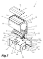
- the illustrated punch 1 consists of several individual components, which are merely inserted into one another and thus without Ausenskar, such as screws and nuts, the Aus GmbH found. As a result, a possible quick and easy assembly of the stamp 1 is achieved, since the items only need to be inserted into each other. Furthermore, the stamp 1 is designed such that only a small number of different parts is needed, wherein for producing a stamp image of the stamp 1 is formed only of six different components, so that as possible cost-effective production is achieved. In order to further reduce the cost of such a die 1, most components are preferably formed from plastic injection molded parts. In this case, the stamp 1 consists of an upper part 6, a lower part 7, a pressure plate carrier 8, a spring 9, the stamp plate 3 and the additional ink pad 4, which is usually arranged interchangeable and can be replaced as a spare part.
- a plug-in and snap-in viewing window 10 is arranged on the upper part 6 so that a printed on a sheet of paper, etc. stamp stamped cut and then inserted between the upper part 6 and window 10 can be inserted. Since the viewing window 10 is formed of a transparent plastic, the user can see through the viewing window 10 behind the inserted paper with the stamp imprint thereon. At the upper part 6 a recess 11 corresponding to the viewing window 10 is formed, the viewing window 10 having on one longitudinal side two latching elements 12, 13 located in the edge region and on the other, parallel longitudinal side in the center another latching element 14 with handle element 15 formed thereon.
- the locking elements 12 to 14 engage in locking recesses 16 of the upper part 6, so that when pressing the viewing window 10 on the upper part 6 a locking connection is made and a secure hold of the viewing window 10 is generated on the upper part 6.
- the recess 11 is formed for the viewing window 10 in the upper part 6 such that when inserting the viewing window 10, the outer surface of the viewing window 11 does not dominate the outer contour of the upper part 6, but ends with this form-fitting.
- the viewing window 11 is preferably arranged on an upper side 17 of the upper part 6 and may extend into a front and / or rear side 18, 19. Of course, it is possible that the viewing window 11 is arranged only in the front and / or rear side 18, 19 of the upper part 6.
- the viewing window 10 is fixed on one side with a rotation axis on the upper part 6, so that the user when opening the viewing window 10 via the grip element 15 can now turn this over the pivot axis.
- the indentation 11 for the viewing window 10 is formed such that a free space (not shown) is provided between the viewing window 10 and the bottom of the indentation 11, in which objects can be stored for storage.
- the recess 11 a few millimeters, in particular 5mm, deep, so that, for example, office hardware, especially paper clips, can be stored and thus the viewing window 10 for removal of Paper clips must be opened often, which is worth arranging a rotation axis for operator comfort.
- a permanent magnet is injected or glued, so that when inserting paper clips these are held in the recess 11. It is also possible, instead of a viewing window 11 to arrange an opaque closure lid.
- a stamp 1 is realized with an ink pad 4, wherein the pressure plate carrier 8 performs only a quarter circle movement, wherein the punch 1 essentially of a telescoping upper and lower parts 6, 7 and a pivotally mounted in the lower part 7 Pressure plate carrier 8 for receiving the stamp plate 3, wherein the printing plate support 8 is associated with a receiving device 21 for a stamp pad 4 and the printing plate support 8 in a rest position 2 in the range between 80 ° and 135 °, in particular from about 90 °, to a footprint 22nd the punch 1 is positioned and is adjustable from this rest position 2 in an operating position 5 for generating a stamp imprint on guide means.
- the turning mechanism for the pressure plate carrier 8 is formed such that in the narrowest space of the pressure plate carrier 8 is rotated in the interior 24 of the lower part 7 and thereby optimal space utilization for a stamp surface 25 is achieved in order to produce the largest possible stamp image can ,
- the stamp surface 25, which corresponds approximately to the size of the printing plate support 8, at least greater than 60%, preferably between 75% and 80% of the total bearing surface 26 of the stamp 1. This is achieved in such a way that rotation of the printing plate support 8 takes place via two guide pins 27, wherein a guide pin 27 is arranged on a side surface 28 of the printing plate support 8, and these simultaneously engage in guide grooves 29, 30 in the lower part 7 and upper part 6.
- the pressure plate carrier 8 is designed such that it has the largest possible base body 31 for receiving a stamp plate 3 as large as possible, to the side of the side surfaces 28, each with a guide pin 27 are formed. Furthermore, the printing plate support 8 extending in the longitudinal direction, a central web 32 between the both side surfaces 28, which supports the two side surfaces 28 and at the same time ensures high stability.
- the mounting of the stamp plate 3 takes place on the opposite planar mounting surface 33 of the base body 31, which is assigned to the stamp pad 4 when the die 1 is mounted.
- the length and width of the printing plate support 8 is adapted to the interior 24 of the lower part 7, since this is completely positioned in the interior 24 and only the guide pins 27 protrude from the interior 24 of the lower part 7.
- the base body 31 is only a few percent, in particular 5%, smaller than the surface of the inner space 24 is large, so that a very high Stempel perennialausnützung of at least 60%, preferably between 75% to 80% of the footprint 26 of the punch 1 is achieved ,
- the size of the mounting surface 33 depends on the structure of the main body 31, since it must be ensured that the pressure plate carrier 8 can be rotated without contact in the interior 24 of the lower part 7.
- any known from the prior art mounting method can be used, preferably the stamp plate 3 is glued to the mounting surface 33.
- Rasteinbuchtungen are arranged, wherein 3 corresponding locking pins are arranged on the stamp plate, so that the stamp plate 3 is simply pressed and engage the locking pin in the Rasteinbuchtungen. It is also possible that the locking pin can protrude through the base body 31.
- the pressure plate carrier 8 can be accommodated with the guide pin 27 in the lower part 7, the lower part 7 on each side surface 34 an arcuate guide groove 29 which extends vertically from the contact surface 22 and then ends in an arc.
- the arcuate guide groove 29 is formed such that the arranged on the side surfaces 28 of the pressure plate carrier 8 guide pin 27 is guided as free of play and in the assembled state of the guide pin 27 from the interior of the lower part 7, ie the interior 24, through the guide groove 29 leads to the outside , Since the guide groove 29 extends into the edge region of the side wall 34, the pressure plate carrier 8 simply needs to be inserted into the guide groove 29 for assembly.
- a guide portion 36 is recessed or recessed formed in the lower part 7 in the region of the arcuate guide groove 29 over the entire height 35 of the lower part 7. It is thus achieved that, with a low component thickness, the largest possible protrusion of the guide pin 27 the guide groove 29 is provided for further engagement in the further guide groove 30 on the upper part 6, and thus the upper part 6 and the lower part 7 are held securely to each other via the two guide pins 27, ie, that the upper part 6 and the pressure plate carrier 8 are connected to each other, wherein the upper part 6 is thereby slipped over only the guide pin 27 of the pressure plate carrier 8 and this engage in the guide groove 30 in the upper part.
- the lower part 7 is inserted only between the two parts, so that then the upper part 6 can be slipped over the lower part and the interior of the rigidly connected to the upper part 6 pressure plate carrier 8 can accommodate.
- the outer contour of the lower part 7 is correspondingly adapted to the interior 37 of the upper part 6, so that the lower part 7 can be pushed into the interior 37 of the upper part 6 at least partially, wherein the individual parts are preferably rectangular
- the guide region 36 in the lower part 7 serves at the same time as a guide for the upper part 6, for which a vertical guide region 38 is formed on the side walls 39 corresponding to the guide region 36 in the upper part 6, so that the vertical guide region 38 along the edges 40 of the guide region 36 on the height 35th the lower part is positioned and / or guided.
- the vertical guide portion 38 may be formed as a full-surface projection / survey or it may be formed individual webs in the interior of the upper part 6, which are formed so that they protrude into the recess, ie in the guide portion 36, and thus in turn over the edges 40th are guided.
- the guide groove 30 of the upper part 6 for the guide pin 27 of the printing plate support 8 in the vertical guide portion 38 is integrated, ie, that the vertical guide portion 38 for telescoping the upper part 6 and lower part 7 and at the same time when nesting for the rotational movement of the pressure plate carrier 8 by the guide grooves 30 is responsible.
- the guide groove 30 in the upper part 6 is arranged such that it first extends horizontally and then ends in a slight arc in the direction of the lower part 7, ie that the guide groove 30 is aligned more horizontally and is responsible for the horizontal displacement of the printing plate support 8.
- the guide groove 30 in the upper part 6 is rotated by 90 ° to the guide groove 29 in the lower part 7, that is, the guide groove 29 in the lower part 7 is mainly responsible for the vertical displacement, whereas the guide groove 30 in the upper part for horizontal displacement responsible is. It is essential that the arcuate end of the guide groove 30 in the upper part 6 with the arcuate end in Lower part 7 match, so that a corresponding turning mechanism described below can be generated.
- notches 42 are provided in the illustrated embodiment laterally parallel to the vertical guide portion 38, whereas on the opposite side of the side wall 39 and front 18 of the upper part 6 discontinued, so the side wall 39 and front 18 are formed shortened, so that it is also achieved that accessibility to the receiving device 21 is given in the assembled state, since this is no longer or only partially covered, so that the insertion of the ink pad 4, however, is possible without problems.
- extension 43 is formed in the vertical guide region 38, which ensures that when assembling this area, so the extension 43 with the guide groove 30, easily deformed, in particular can be pressed outwards, since less material must be deformed , And thus the upper part 6 can be easily slipped over the guide pin 27 of the pressure plate carrier 8 for engagement in the guide groove 30.
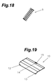
- the upper part 6 and lower part 7 each have a spring receiving device 44 into which the spring 9, in particular a spiral spring, is inserted and positioned.
- the spring 9 has the task to produce a corresponding pressure between the upper part 6 and lower part 7, so that the two parts are in the rest position 2, so when not pressing the punch 1, always in a defined position to each other and at the same time the stamp plate 3 against the Stamp pad 4 presses. In this case, the upper part 6 and the lower part 7 are pressed apart via the spring 9.
- a T-shaped webs 45 is formed for this purpose in the illustrated embodiment, in the center of a lower trained in its height circular web 46, on which the spring 9 is placed, is arranged, so that the spring 9 between the T-shaped Webs 45 and the back 19 is positioned.
- a shoulder 47 is arranged in the lower part 7, in which an X-shaped web 48 is formed, wherein the X-shaped web 48 corresponds to the diameter of the spring 9 so that it can be inserted over the web 48 and the spring 9 in turn positioned and is held.
- a shoulder 47 ensures that the distance and thus the spring travel between the upper part 6 and lower part 7 is extended, so that, for example, a longer spring 9 can be used with a higher pitch for a lower spring pressure and thus the stamp comfort is improved since the user does not have to apply that much pressure. It is also achieved that the two parts can be pressed closer to each other, since the spring 9 during pressing of the paragraph 47, ie the indentation, is taken, so that the upper part 6 can thus be pressed directly onto the lower part 7.
- the shoulder 47 causes a stop or abutment surface 50 for the pressure plate carrier 8 to be created in the interior space 24 of the lower part 7, which is simultaneously used as an anvil for initiating the rotational movement of the pressure plate carrier 8.
- the turning process is now carried out such that upon actuation of the punch 1, the upper part 6 is pushed over the lower part 7 against the spring force of the spring 9, wherein at the same time the guide pin 27 in the guide grooves 29, 30 are moved accordingly, so that due to the interaction of the guide 29th , 30 a defined sequence for the movement of the printing plate support 8 is generated, in particular a lifting of the printing plate support 8 is performed by the ink pad 4 with subsequent rotational and vertical movement.
- the printing plate support 8 is lifted from the insert 51 of the stamp pad 4, ie, that the shift in horizontal plane is due to the formations of the two guide grooves 29, 30, wherein due to the guide groove 30 in the upper part 6 of the printing plate support 8 is moved horizontally and is simultaneously lowered by the arcuate course of the guide groove 29 in the lower part 7 slightly towards footprint, the lowering only slightly in the first phase.
- the central web 32 acts in the rotational movement, since it stops the movement of the printing plate support 8 in a certain position, ie, that the base body 31 and the central web 32 exactly enclose the shoulder 47 so that over-rotation is not possible.
- the pressure plate carrier 8 mainly a vertical movement performs and is thus pressed against the footprint 22 of the punch 1. In this case, a stamp imprint is thus generated in the interior of the support surface 26 when mounted stamp plate 3, so that the stamping process is completed.
- the upper part 6 can be easily let go of the user, so that it is now automatically lifted by the spring 9 from the lower part 7 and pushed back into the rest position 2.
- the printing plate support 8 is now rotated in the opposite direction, so that it is aligned parallel to the ink pad 4 and comes to rest in the rest position 2 on the ink pad 4.
- the ink pad 4 has the task to provide the mounted on the printing plate support 8 stamp plate 3 with color for a stamping process, that is, that the ink pad 4 a color impregnated insert 51, as shown schematically in FIG Fig. 4 indicated, on which the stamp plate 3 rests with light pressure, so that the stamp plate 3 in the rest position can absorb color from the insert 51.
- the printing plate support 8 is arranged at a certain angle to the footprint of the stamp 1, it is necessary that the ink pad 4 is assigned to the printing plate support 8, ie, that the ink pad 4 at an angle between 80 ° and 135 °, preferably is arranged at about 90 °, the footprint 22 of the stamp 1.
- the printing plate support 8 and the ink pad 4 are aligned parallel to each other, wherein the plate plate 3 mounted on the printing plate support 8 is pressed by the printing plate support 8 with slight pressure against the insert 51, so in the direction of inking the ink pad 4 is applied.
- the stamp plate 3 Since the printing plate support 8 is arranged in the lower part 7, the stamp plate 3 is housed therein.
- the receiving device 21 is arranged in the lower part 7, in which the ink pad 4 is inserted or taken from this in ink exhausted to a new or freshly soaked with ink stamp pad 4 again.
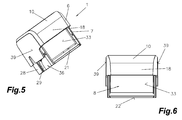
- the receiving device 21 for the ink pad is arranged in the lower part 7, that in the rest position 2 of the stamp 1 is a free accessibility to the printing plate support 8 on the side surface of the lower part 7 is given, ie that when not used ink pad, as in Fig. 5 illustrated, the user can get over or through the disposed on the front side 34a receiving device 21 directly to the printing plate support 8, since this is aligned in the rest position 2 parallel to the receiving device 21.
- the ink pad 4 inserted into the receiving device 21, the ink pad 4 closes the receiving device 21.
- the receiving device 21 for the ink pad 4 is arranged on the front side 34a of the lower part 7, wherein the receiving device 21 is designed in the form of a window with means for receiving the ink pad 4 arranged therein, so that when the ink pad 4 is not used directly arranged on the inside of the lower part 7 and arranged parallel to the receiving device 21 aligned printing plate carrier 8 is accessible. Since in the rest position 2 from the printing plate support 8 always a slight pressure against the ink pad 4 is exercised, it is necessary that this is well held in the receiving device 21, since this otherwise parallel to the printing plate support 8 of this from the receiving device 21 and thus from the Lower part 7 would be pressed. To prevent this, the receiving device 21 has means 74 for fastening and positioning and guiding. Correspondingly, such means 74 for positioning, holding and releasably fixing the stamp pad 4 in the receiving device 21 are also arranged on the stamp pad 4.
- the receiving device 21 is designed in the form of a window or an opening, on which support surfaces 52 for resting the stamp pad 4 are arranged and means, in particular at least one fastening element 55 and one or more recesses 54 and / or projections, for fixing and positioning of the stamp pad 4 are arranged.
- any known from the prior art solution for fixing and positioning of an object can be used, including always the two parts, ie the receiving device 21 and the ink pad 4, are formed corresponding to each other.
- the ink pad 4 is correspondingly composed of an ink pad carrier 56 and a liner 51 arranged therein for receiving ink, wherein means for insertion into and / or removal from the stamp 1, in particular from the receiving device 21, are arranged on the ink pad carrier 56.
- a deformable means for fixing in a stamp 1 is arranged on at least one of the side surfaces, in particular a longitudinal side 57, the punch pad carrier 56 and at least one further side surface, in particular on the further longitudinal side 57, a positioning element, in particular in shape a recess and / or a projection 58, arranged.
- the positioning element in particular the projection 58
- the ink pad 4 is pressed completely into the receiving device 21, whereby the deformable means snaps into the fastening element 55.
- the means on the ink pad 4, in particular the projection 58 for example, specially designed to build a holding pressure for the ink pad 4 in the receiving device 21.
- the deformable means 74 is formed in the illustrated embodiment such that the means is formed in the form of a bracket 59 and the bracket 59, a projection or a recess is arranged, ie, that an ink pad is provided, which consists of an ink pad carrier and arranged therein Insert 51 for receiving ink, and disposed on the ink pad carrier means for insertion into and / or removal of a stamp 1 are arranged, wherein at least one of the side surfaces of the ink pad carrier 56, a deformable means for fixing in a stamp 1 is arranged the means in the form of a bracket 59 is formed and the bracket 59, a projection 60 or a recess is arranged, which is designed for snapping or fastening on the fastening element 55.
- the bracket 59 is formed in the form of a handle.
- the bracket 59 extends over the entire side surface, in particular longitudinal side 57, wherein in the outer edge region of the bracket 59 is connected to the ink pad carrier 56.
- a clearance 61 is present between the bracket 59 and the ink pad support 56, so that it can be deformed in the direction of ink pad carrier 56 by pressing on the bracket 59, so that the ink pad 4 from the fastener 55 and the receiving device 21 are solved can.
- further means for positioning and / or mounting in the form of protrusions 60 and / or recesses are arranged on the side opposite the bracket 59 side.
- stamp pad 4 Due to the special design of the stamp pad 4 and the special arrangement in the front 34a of the lower part 7 of the sequence for a change from the known from the prior art procedure is changed. It can be said that a method for changing an ink pad 4 is carried out in a stamp 1, wherein a pressure or stamp plate 3 mounted on a bottom, in particular mounting surface 33, of a printing plate support 8 at rest in a receiving device 21 arranged stamp pad 4 is applied, wherein upon actuation of the punch 1, the stamp plate 3 is lifted and pivoted from the rest position 2 in an actuating position 5 for generating a stamp impression of the insert 51, wherein in the rest position 2, the ink pad 4 from its position in the receiving device 21 is released and is then removed in the opposite direction to the underside of the pressure plate carrier 8 from the receiving device 21, ie, that a free accessibility from the outside to the ink pad 4 in the lower part 7, in particular to the Front side 34a of the lower part 7, is given, and that the ink pad 4 is first released from the receiving device 21
- stamp plate 3 is first mounted, since in the manufacture of the stamp 1 only from the parts, upper part 6, lower part 7, pressure plate carrier 8, spring 9 is formed.
- the ink pad 4 is designed as a spare part and is generated independently of the stamp 1. Also, it is not necessary that the viewing window 10 must be present.
- the user selects a stamp 1 and then created preferably on a specially designed graphics software a stamp image. This stamp image is transmitted to a laser printer, for example, which generates the stamp plate 3 from a blank by appropriate processing. Subsequently, the stamp plate 3 must be mounted on the printing plate support 8. This was done in the prior art usually in the operating position 5 of a stamp. 1
- the mounting of the stamp plate 3 in the rest position 2 of the punch 1 takes place, the stamp plate 3 is guided by the receiving device 21 in the interior 24 of the lower part 7 and then positioned on the mounting surface 33 and fixed becomes. It can therefore be said that a method for mounting a printing plate or stamp plate 3 in a stamp 1, wherein the stamp plate 3 is assigned in the rest position 2 of a receiving device 21, wherein upon actuation of the stamp 1, the stamp plate 3 from the rest position 2 in a Actuation position 5 is pivoted for generating a stamp imprint is created, the assembly of the stamp plate 3 in the rest position 2 via the receiving device 21 in the lower part 7 takes place and the receiving device 21 is formed for receiving an ink pad 4.
- the ink pad 4 on the front side 34a of the lower part 7 is arranged, wherein the ink pad 4 is taken parallel to the front side 34a and is inserted into the stamp 1.
- the advantage is that the user can easily get to the ink pad 4 and can see the majority of the ink pad 4, so that better handling when inserting or swapping the ink pad 4 is achieved.
- the dimensioning of the stamp 1 is preferably designed such that the receiving device 21 for the ink pad 4 occupies almost complete the front 34a, that is, the height 35 is approximately equal to the narrow side of the stamp pad 4.
- the size of such a stamp 1 is substantially reduced, but the largest possible space utilization for the stamp plate 3, which corresponds approximately to the size of the surface of the stamp pad 4, is utilized.
- the upper part 6 is formed in such a way that the inner space 37 receives the lower part 7, in particular the inner space 37 also has the height 35, so that the lower part 7 is completely positionable in the interior 37 of the upper part 6.
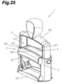
- a further embodiment of a self-inking stamp 1 of another type is shown.
- this self-inking stamp 1 is a 180 ° -Wender, ie that the turning mechanism is designed such that the printing plate support 8 once completely rotates about its axis.
- the terms used in the above-described figures are applied to this embodiment.
- the punch 1 consists of a telescoping upper part 6 and lower part 7 and a pivotable arranged in the lower part 7 plate carrier 8 for receiving the stamp plate 3, wherein the printing plate support 8 is associated with a receiving device 21 and the printing plate support 8 in a rest position 2, as shown in the Position of 180 ° to a footprint 22 is positioned, this is from this rest position 2 in an operating position 5 (not shown) for generating a stamp imprint on guide means is adjustable and the upper part 6 is U-shaped formed as an operating bracket 65, wherein the upper part 6 is distanced from the lower part 7 on the two sides of the U-shaped actuating bracket 65 from each other, as is already known from the prior art.
- the lower part 7 has been redesigned.
- the receiving device 21 is arranged for the ink pad 4 in the lower part 7, wherein the receiving device 21 is formed such that in the rest position. 2 the plunger 1 is given a free accessibility to the printing plate support 8 via an upper surface 66 of the lower part 7, ie that now the receiving device 21 is disposed below the operating bracket 65 on the lower part 7 and the user on the between the top 66 of the lower part 7 and the operating bracket 65 formed cavity 67 can reach the receiving device 21.
- the pressure plate carrier 8 Directly below parallel to the receiving device 21 is also the pressure plate carrier 8 when the punch 1 is in the rest position 2.
- the operating bracket 65 does not necessarily have to be provided with a handle member, but can be easily formed by a U-shaped bracket. It must only be ensured that you can get between the operating bracket 65 and the lower part 7 to the receiving device 21, so a free accessibility to the receiving device 21 is given.
- the difference between the two exemplary embodiments lies in the fact that the receiving device 21 for the ink pad 4, and with the ink pad 4 inserted, itself on the front side 34a of the lower part 7 (90 ° punch) and on the other side on the upper side 66 of the lower part 7 (180 ° -Stempel) is arranged.
- the ink pad 4 with a viewing window 10 is equipped, ie, that the ink pad carrier 56 on the opposite side for receiving the insert 51 has a recess 11. This can in turn be provided with detent recesses 16, so that the viewing window 10 can be pressed with molded thereon locking elements 12 to 14 on the ink pad 4, in particular on the back. Thus, in turn, a generated stamp imprint can be inserted, which is visible through the transparently formed viewing window 10.
- the Arrangement of a viewing window 10 on the ink pad 4 is also possible in the embodiment described above and embodiments described below.
- the viewing window 10 is simply plugged onto the ink pad 4 and encloses this. It only has to be ensured that the ink pad 4 can be inserted into the receiving device 21.
- FIG. 27 Another embodiment is in Fig. 27 shown. Here, however, the representation of the stamp 1 is dispensed with, wherein only the pressure plate carrier 8 is shown.
- This printing plate support 8 corresponds essentially to the structure in the previously described embodiment, so that it can be used in the previously described stamp 1.
- the stamp 1 is formed as a pre-inked stamp 1, for which the main body 31 of the printing plate support 8 is designed to receive a pre-inked stamp plate 68, ie, that the base body 31 has a latching frame 69, in the pre-inked stamp plate 68 is inserted.
- This ensures that now no ink pad 4 is required more, but the stamp image is generated directly from the printing plate support 8, in particular the pre-inked stamp plate 68 located therein.
- the ink is stored in a storage medium 70 in the printing plate support 8 and can seep out from there through the pre-inked stamp plate 68, as indicated schematically by an arrow 71.
- the pre-inked stamp plate itself may be formed as a storage medium.
- a cover plate (not shown) are inserted, whereby the opening and access to the printing plate support is closed. It can therefore be said that the receiving device 21 for receiving an ink pad 4 and / or a cover plate, which remains in the receiving device 21 upon actuation of the stamp 1, is formed. It is also possible that such a cover plate is always used in the delivery of the stamp 1, and the user then replaced by a stamp pad 4, in an embodiment of a self-inking stamp 1. Basically, there would also be the possibility that the user himself decides whether he has one would like to use self-inking stamp 1 or a pre-inked stamp 1, since he only needs to replace the printing plate support 8.
- stamp pads 4 for use in the stamps 1 previously described are shown. It should be mentioned that the integrated in the stamps 1 receiving device 21 is formed corresponding to the illustrated ink pad 4, so that it can be inserted into the receiving device 21.
- Fig. 28 an embodiment in which as a means 74 of the bracket 59 is disposed on a longitudinal side 57, whereas on the opposite side further means 74, in particular two pins 75 and a pin receiving 76 shown in broken lines for corresponding pin 75 (not shown) on the receiving device 21 of Stamp 1, are arranged.
- the pin 75 know while a special design and can be formed, for example, tapered.
- the pins 75 can be fastened to the stamp pad carrier 56, for example via a latching connection, ie, for example, a guide with or without notch is arranged above the basic body thickness, so that the pad 51 is exposed from one side, in particular from that side , postponed.
- an ink pad 4 in particular a basic embodiment, can be produced for different stamps 1 with different receiving devices 21, where only the correspondingly required means 74 are plugged in, ie, for example, different lengths and / or thick extensions 75 can be plugged.
- the gripping elements 77 are eccentrically arranged in the region of the bracket 59, since thereby the user first advances the stamp pad 4 with the pins 75 obliquely into the receiving device 21 and then completely pushes the ink pad 4 into it.
- the grip elements 77 In order for the user to have a better grip, it is possible for the grip elements 77 to be provided with nubs or grooves. It is also possible that these are also designed to be removable. For this purpose, it is generally mentioned that all means 74 shown in the exemplary embodiments can be designed to be removable.
- the ink pad 4 is formed such that now a special design of a locking mechanism 79 is used for fixing the ink pad 4 in the receiving device 21.
- the movable means 74 is arranged on the receiving device 21, that is, the ink pad 4 is equipped only with hardly deformable means 74 and for fixing in the receiving device 21 of the so-called deformable bracket 59 is equipped with a movable fixing lip 80.
- the fixing lip 80 can be pressed down by the user in the direction of footprint 22, whereby the fixation of the ink pad 4 is released and thus the ink pad 4 can be removed, that is released by pressing down the fixing lip 80 arranged on an ink pad 4 locking lug 81 is so that the user can hold the ink pad 4 to the handle members 77 and can pull out of the receiving device 21.
- the mechanism may be designed such that an extension of the fixing lip 80 is actuated by the ink pad 4, so that the fixing lip 80 folds up and the ink pad 4 and the locking lug 81 locked because the fixing lip 80 in a snap connection locks.
- a lower edge 82 of the front side 18 of the upper part 6 terminates in the rest position 2 with the upper edge or an upper edge 83 of the receiving device 21 or projects only slightly beyond it.
- the lower edge 82 of the front side 18 protrude slightly above the receiving device 21 or the ink pad 18 can, but care must be taken that the ink pad 4 can still be easily unscrewed.
- the handle members 77 may protrude beyond the side edges of the lower part 7, if they are arranged accordingly, ie, the handle members 77 in the area of the footprint 22, so arranged in the lower region, so a total width 84 of the grip elements 77 longer be, as a width 85 of the lower part 7, since when pressing the punch 1 by the shortened design of the front 18 this in turn ends in the operating position 5 above the grip elements 77.
- the grip elements 77 are laid more in the middle region of the stamp pad 4, then the overall width 84 must be equal to the width 85 of the lower part 7, so that the upper part 6 can be pushed over the grip elements 77.
- the punch 1 is shown in the rest position 2 and the pressure plate carrier 8 is not yet coupled to the upper part 6, but only in the lower part 7 is inserted.
- the release of the stamp pad 4 is performed by a pressurization and a simultaneous sliding movement, for which purpose only only the lower part 7 and the ink pad 4 are shown. It is also possible that an unlocking can be performed without pressurization.
- spring elements 86 which press this with inserted tamping pad 4 in the direction of support surface 22.
- the spring elements 86 can be formed for example by simple deformable tabs, straps or the like, but always return to a deformation in the original form. It is possible that only one or more spring elements 86 are arranged. It is also possible for these spring elements 86 to be formed directly on the stamp pad 4 and, when inserted, press in the direction of the bearing surface 22.
- insbesondre locking projections 87 formed, which are now aligned 90 ° to the ink pad carrier 56, that is, in the direction of the lower part 7 protrude.
- These means 74 rested in corresponding openings 88 on the lower part 7 and the receiving device 21, wherein the openings 88 are formed substantially larger than the latching projections 87, so that the latching projections 87 are slidable in the openings 88. It is also possible that instead of openings 88 only corresponding snap-in intersections are arranged, in which the latching projections 87 can engage.
- the user presses first against the ink pad 4 in the direction of the lower part 7, and simultaneously pushes the ink pad 4 up against the spring elements 86, so that the locking projections 87 are released in the opening 88 from its locking connection and the ink pad 4 are removed can.
- a symbolic arrow 89 is shown to represent the direction of displacement on the ink pad carrier 56.
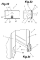
- Fig. 34 an enlarged view of an embodiment is shown in which means 74 are arranged on the grip elements 77 for latching on the lower part 7.
- the means 74 is formed for example as a latching extension 87.
- the ink pad 4 and the receiving device 21 can also be carried out inversely as in the embodiments described above, ie, that the means 74 from the ink pad 4 in the receiving device 21 and the means 74 of the receiving device 21st be arranged on the ink pad 4.
- the latching projections 87 engage in openings 88 on the lower part 7 and thus fix the stamp pad.
- the two gripping elements 77 have to be pressed together a little, whereby the locking connection is released and the ink pad can be removed, ie that now press together by the pressing together of the grip elements 77 and thus pressed the latching projections 87 out of the opening 88 become.
- the receiving device 21 is provided with a means 74 which is elastically deformable. This is formed by special formations of the edge region and corresponds to a resilient projection 90, which presses with inserted ink pad 4 this in a particular direction, in particular in the direction of the footprint 22.
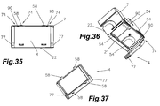
- this now has a plurality of, in particular four, projections 58, wherein these are divided on the longitudinal side 57, that is, on each longitudinal side 57, two projections 58 are arranged.
- corresponding recesses 54 are arranged in the receiving device.
- the ink pad 4 is pressed according to the graphic symbol against the resilient projection 90 and then swung out or pressed.
- a further variant of a connection system for the ink pad 4 and the receiving device 21 is shown.
- the ink pad 4 is pushed in the direction of footprint 22 to solve this.
- a corresponding graphic symbol is arranged. To fix the ink pad 4 is pushed against this movement.
- the fixing takes place in turn via correspondingly arranged means 74 on the stamp pad 4 and on the receiving device 21.
- a latching hook 91 is arranged on the lower part 7, in particular in the edge region relative to the grip elements 77 on the receiving device 21.
- a stop element 92 is arranged, against which the stamp plate 4 can be pressed. Between latch hooks 91 and stop element 92, a free space is arranged, in which a latch hook 91 corresponding locking element 93 can engage.
- the ink pad 4 is inserted into the receiving device 21, so first the protrusions 58 inserted into the recess 54 and then the locking element 93 inserted into the space between latching hooks 91 and stop element 92, and then upwards, ie against the footprint 22, pushed so the latching hook 91 is deformed and then locks in the locking element 93. To release the ink pad 4 is now powerfully moved in the direction of arrow 89, so that the latching hook 91 is again deformed and the locking member 93 is free, so that the ink pad 4 can be easily removed.
- protrusions 58 it is possible for protrusions 58 to be arranged in the area of the grip elements 77, so that a four-point positioning is created, with all protrusions 58 now projecting in the same direction.
- stamp 1 and / or the individual parts or the stamp pad 4 are achieved in an advantageous manner that the size compared to known from the prior art punches with comparable stamp impression size by about 40% is reduced. This is also achieved in an advantageous manner that the actuation path for the user is reduced, but the stamp image quality is obtained. Reducing the size of the stamp also reduces the amount of material used and thus reduces the cost of manufacturing.
- the stamp can be equipped with a fixing device, so that the stamp can be fixed in the rest position 2 and thus the ink pad can be inserted or removed. Also, thus, the stamp plate 3 can be used in a fixed position. It can therefore be said that this type of stamp 1 can be used unlocked and / or locked.
- the means 74, in particular the resilient projection 90, shown enlarged in order to better recognize the operation of the means 74, in particular of the projection 90 can.
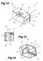
- the projection 90 is preferably formed integrally from the lower part 7 and preferably has a material taper 95a on a surface 95 of the lower part 7, ie, that the projection 90 is arranged on the surface 95 of the lower part 7, which faces the contact surface 22 is formed and the projection 90 deformed back to its original position after deformation.
- the lower part 7 is thus made with the resilient projection 90 from a single injection molding tool.
- the receiving device 21 forms a frame-shaped opening for insertion of the stamp pad 4, wherein via a window 96 in the interior 24 of the lower part 7, in particular to the pressure plate carrier 8, can be reached.
- the projection 90 is positioned so that it protrudes into the interior of the receiving device 21 or closes it, so that when inserted pad 4 of the resilient projection 90 builds or exerts pressure on the ink pad 4, as this deformed from the ink pad 4 at the onset was, ie, that the resilient projection 90 in the frame-shaped Opening protrudes and when inserting the ink pad 4 through the ink pad 4 to the rear, ie in the opposite direction to the footprint 22, is pressed, whereby due to the spring force of the means 74, in particular of the projection 90, a force is exerted on the ink pad 4 and thus the ink pad 4 is pressed by the projection 90 in the direction of the footprint 22.
- the projection 90 is formed back into its initial position and thus in turn protrudes slightly into the frame-shaped receiving device 21 and closes with this.
- the resilient means 74 in particular the projection 90, can also be formed as an extra part or component and is fastened or positioned on the lower part 7, which is then again inserted in such a way that when the ink pad 4 is inserted in the receiving device 21 of the means 74, a pressure in the direction of footprint 22 is constructed.
- two recesses 54 are arranged on the surface 95, so that corresponding projections 58 on the ink pad 4 can be inserted into it.
- the projections 58 have the task to position the ink pad 4 and to avoid tipping, since the printing plate support 8 presses against the ink pad 4.
- the two recesses 54 are arranged, for example, between the two projections 90, wherein in the illustrated embodiment, the two projections 90 are arranged in the areas of the side surfaces 34 on the surface.
- two projections 90 and / or recesses 54 only a single projection 90 and / or recess 54, which are preferably arranged in the central region of the receiving device 21, is used, or that more than two projections 90 and / or Recesses 54 are arranged.
- the projection 90 is formed such that it is designed to build up a pressure in the direction of the contact surface 22 when the ink pad 4 is inserted or that when the ink pad 4 inserted this is pressed by the projection 90 in the direction of contact surface 22 and that the recess 54th for receiving means, in particular of projections 58 of the stamp pad 4, is formed.
- the resilient projections 90 may be arranged on the opposite side in the region of the contact surfaces 22, wherein these in turn protrude into the inner region of the receiving device 21 or with this almost complete.
- the projections 90 now have the task to press the ink pad 4 in the direction of the surface 95, ie opposite to the previously described direction.
- the previously described embodiment in which the protrusions 90 are positioned on the surface 95 is preferred. Also, a combination of different positions would be possible.
- a longitudinal web 98 is arranged in the area of the contact surface on a bearing surface formed for the ink pad 4, in which in turn two recesses 54 are arranged.
- the longitudinal web 98 is preferably arranged close to the opening or the window 96 of the receiving device 21, so that a corresponding distance 99 is formed or provided for the bearing surface 22, ie, that the receiving device 21, in particular the window 96 of the receiving device 21, not extends to the footprint 22, but is formed smaller by the distance 99 and is set back.
- the lower part 7 with the receiving device 21 is thus designed such that it is formed corresponding to the special ink pad 4 and thus can accommodate this. It is important to ensure that all parts or components are arranged and integrated so that they can be taken in a stamping operation in the interior of the upper part 6.
- the surface 95 of the lower part 7 forms the maximum outer contour over which no parts may protrude.
- the support surface 97 is offset in the region of the footprint 22 by a thickness 100 of the ink pad 4 back and thus can absorb the ink pad 4, that is, the ink pad 4 can rest on the support surface 97.
- the longitudinal web 98 is arranged over at least a portion of the length, which protrudes in the opposite direction of the interior 24.
- the longitudinal web 98 is preferably formed smaller than the thickness 100 of the stamp pad 4th is such that upon insertion of the ink pad 4, the longitudinal web 98 is received in the ink pad 4, ie, that in the ink pad 4, a recess or clearance 109 is formed, protrudes in the inserted ink pad 4 of the longitudinal web 98 or the ink pad 4 is formed such in that the ink pad 4 can be arranged between the surface 95 and the longitudinal web 98, whereby the longitudinal web 98 forms the terminating element or only partially overtops the ink pad 4 beyond the longitudinal web 98, ie the ink pad 4 is arranged only between the surface 95 and the longitudinal web 98 or that only over a portion of the length of the longitudinal web 98 and the lower part of the ink pad 4 projects beyond the longitudinal web 98.
- the two recesses 54 for the corresponding projections 58 of the stamp pad 4 are arranged on the longitudinal web 98.
- a surface 102 tapering in the direction of the opening of the receiving device 21 is formed on the longitudinal web, so that the projection 58 is more easily guided over the surface 102 in the direction of the recess 54 when inserting the stamp pad, so that the insertion of the stamp pad 4 is greatly facilitated, since the projections 58 simply slip over the inclined surface 102 into the recess 54 and can be pressed.
- a side guide 103 is arranged in the lower part 7.
- the side guide 103 extends from the surface 95 in the direction of footprint 22 and terminates at a defined distance 104 to the footprint 22, wherein the distance 104 is dimensioned such that it can receive a handle member 77 from the ink pad 4, that is, the ink pad 4 such is formed that in this area on both sides grip elements 77 are arranged, which extend from the inside of the side guide to the outside and terminate with the outside.
- a web 105 is arranged between the side guides 103 for supporting the stamp pad 4, whereby the stamp pad 4 can not fall into the interior of the lower part 7.
- the web 105 and the bearing surface 97 form a plane, so that it can be said that the bearing surface 97 extends along the web 105.
- the support surface 97 or the web 105 in the region of the side guide 103 forms only a very narrow web 105 in order to create the largest possible opening or window 96 for the receiving device 21.
- the web 105 should be formed so wide that it is ensured that when inserting the ink pad 4 this is guided on this web 105 and at the same time prevents the ink pad 4 may fall into the interior of the base.
- a self-inking stamp 1 is formed, which comprises a telescoping upper and lower parts 6, 7 and a pivotally mounted in the lower part 7 pressure plate carrier 8 for receiving the stamp plate 3, wherein the printing plate support 8 is assigned a receiving device 21 for a stamp pad 4 and the Print plate support 8 is positioned in a rest position 2 in the range between 80 ° and 135 °, in particular of approximately 90 °, to a footprint 22 and is adjustable from this rest position 2 into an actuating position 5 for generating a stamp imprint on guide means, wherein in the Lower part 7, a resilient means 74 is arranged, which projects into a receiving device 21 for the ink pad 4 or approximately closes with this, and at a further side on the lower part 7 at least one further means 74 for positioning and holding the ink
- the arrangement of the resilient means 74 ensures that the ink pad 4 is pressed in a certain position, so that a secure hold and an exact positioning is ensured. Furthermore, it is achieved that when overcoming the force built up by the resilient means 74, the ink pad 4 can be moved slightly or moved in the receiving device 4, whereby a disengagement or disengagement of the interlocking means 74 is possible, ie, that the means 74 on the ink pad 4 and the means 74 on the stamp 1 are coordinated with each other so that they can be slightly in one direction, in particular against the footprint 22, moved.
- a resilient means 74 is disposed in the lower part 7, which projects into an interior of the receiving device 21 for the ink pad 4 or approximately closes with this, and are on another side on the lower part 7 two further means, in particular two recesses 54 for positioning and Holding the ink pad 4 arranged so that the ink pad 4 can be moved against the resilient means 74.
- the corresponding stamp pad 4 is designed such that it comprises a stamp pad carrier 56 and an insert 51 arranged therein for receiving ink, and arranged on the ink pad carrier 56 means 74 for insertion into and / or removal from a stamp 1 are arranged, wherein on a Longitudinal side surface 106 at least one means 74 is arranged for use in a corresponding means 74 in a stamp 1, and that on another side, a further means 74 for positioning and holding is arranged.
- the stamp pad carrier 56 has a defined thickness 100 to receive the insert 51 and thus to provide a corresponding color supply for a variety of stamping operations.
- the insert 51 is freely accessible on one side of the ink pad carrier 56 and is covered on the other side by the ink pad carrier 56.
- two projections 58 are arranged on a longitudinal side surface 106 of the stamp pad 4, which are formed for use in recesses 54 on the surface 95 of the lower part 7 of the punch 1, wherein on the opposite side again two further projections 58 for use in the Recesses 54 are arranged on the longitudinal web 98 of the lower part 7 of the stamp 1.
- the two projections 58 are arranged on a central web 107 or longitudinal side surfaces, which limits the area for the insert 51.
- the further longitudinal side surface 108 is arranged, wherein between the central web 107 and the longitudinal side surface 108, a free space 109 is formed, which is at least designed such that the longitudinal web 98 can be arranged on the lower part 7 therein, ie that when inserted Ink pad 4 between the central web 107 and the longitudinal side surface 108 of the longitudinal web 98 is inserted into the free space 109, whereby a locking of the projections 58 on the central web 107 into the recesses 54 on the longitudinal web 98 is possible.
- handle elements 77 are formed or arranged on the two narrow side surfaces 110, which project beyond the narrow side surfaces 110 and terminate when the ink pad 4 is inserted with the outer surface of the side guides 103.
- the narrow side surfaces 110 extend within the side guides 103 and complete the grip elements 77 of the stamp pad 4 with the outer surface of the side guide 103.
- a kind of facet 111 is arranged in the side regions of the narrow side surface 110.
- openings 112 are arranged, as shown.
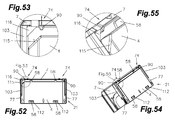
- the ink pad 4 For insertion of the ink pad 4, it is now necessary that the ink pad 4 slightly angle inserted into the side guides we. After the ink pad 4 comes to rest on the projection 90 or the surface 95 of the base 7, the user must now exert a slight pressure in the direction of the surface 95, so that the resilient means 74, in particular the resilient projection 90, is pushed back. At the same time, the stamp pad 4 moves in the direction of the surface 95, so that the projections 58 are pushed over them in the area of the longitudinal web 98 and the stamp pad 4 comes to rest on the bearing surface 97.
- the pressure on the stamp pad 4 is now ended, then it is pressed by the resilient means 74 in the direction of the contact surface 22, whereby the projections 58 in the region of the longitudinal web 98 are pressed into the recesses 54 arranged in the longitudinal web 98.
- four means 74, in particular four projections 58 are arranged on the stamp pad 4 for this purpose.
- these are preferably arranged in pairs on the long sides.
- These means 74, in particular these projections 58 but have a further object, namely that these projections 58 are formed such that they act against the contact pressure of the pressure plate carrier 8 or that the ink pad 4 against these projections 58 against the contact pressure of the Pressure plate carrier 8 is held.
- the means 74, in particular the protrusions 58 are arranged asymmetrically on the ink pad 4, for which purpose the corresponding recesses 54 are formed correspondingly, ie, for example the projections 58 are far different from the edge of the ink pad 4 removed.
- a kind of coding system can be created.
- an ink pad 4 is used, which already ends with the central web 107, that is, that only the portion of the insert 51 is present with the arranged on both sides projections 58, so that upon insertion of the ink pad 4 in the Stamp 1 this is used between the surface 95 with the recesses 54 and the resilient projections 90 and the longitudinal web 98 with the recesses 54, so that the longitudinal web 98 is not surmounted by the ink pad 4, so a shortened ink pad 4 is used.
- the longitudinal web 98 thus forms the conclusion for the ink pad 4.
- a portion of the longitudinal web 98 is surmounted by the ink pad 4 so that this namely easier to remove from the stamp. Namely, if the ink pad ends within the longitudinal web 98, it is hardly possible to easily replace it, since the longitudinal web 98 and the lateral side guides 103 complicate or prevent access to the inserted ink pad 4.
- corresponding locking elements 113 can be used, which allow only a one-time insertion of the ink pad 4, ie, that after insertion of the ink pad 4 this removed only with increased effort again can, in which case usually a locking element 113 is deformed.
- FIGS. 49 to 51 Such an embodiment is in the FIGS. 49 to 51 shown. It can be seen that when the ink pad 4, according to Fig. 50 , between the narrow side surfaces 110 of the stamp pad 4 and the side guide 103, a latching connection 113 is formed, which is difficult to separate. Furthermore, in such a configuration, the gap 114 between the narrow side surface 110 and the handle members 77 and the side guide 103, so that after a snapping of the ink pad 4 in the lower part 7 this can no longer be moved. Of course, it is also possible that between the central web 107 and the longitudinal web 98 this or an additional locking connection 113 is arranged.
- the resilient means 74 are arranged, since the goal is to use the ink pad 4 only once and then to remove this no longer.
- the ink pad 4 can be formed and used without play.
- an additional means 74 in the form of a recess 54 is arranged on the longitudinal web 98, whereby an even better hold of the ink pad 4 in the lower part 7 is achieved.
- the ink pad 4 is formed slightly different and now no longer has the grooves for the grip elements 77 for a secure grip, but there are only the bulges in the form of grip elements 77 available to achieve a planar finish or the optical To preserve appearance of the stamp 1.
- the recesses 54 may be omitted on the surface 95, when the positioning on the resilient projection 90 takes place, that is, for example, on the ink pad 4, a notch is present, into which the projection 90 for Positioning can be used and at the same time, however, the projection 90 is deformed to build up a pressure from the ink pad 4. It is advantageous if the projection 90 is formed such that tilting out of the ink pad 4 from the lower part 7 is avoided. Thus, the projection 90 should push the pad 4 towards the footprint and at the same time press over the projection 90 in the direction of the lower part 7. This can be achieved, for example, by a dreidimenisonale training of the pin on the projection 90, which engages in a correspondingly angular notch on the ink pad 4.
- stamps are becoming increasingly important for stamp 1, since due to the different structures often very similar stamp pad 4 are required, which are not suitable for each stamp 1. This is to ensure that only those ink pads 4 fit in a stamp 1, which are intended or released by the manufacturer. In particular, the case often occurs in replica stamp pads that fit more than bad in the stamp 1 of the manufacturer, with these then usually a bad stamp imprint or a complicated replacement of the replica stamp pad is achieved. This can degrade the reputation of a manufacturer. A bad stamp imprint may, for example, come about when in the rest position the ink pad 4 in the stamp 1 is not completely applied to the pressure plate of the printing plate support 8 and thus can not be sufficiently absorbed color.
- stamp 1 it is nowadays also necessary that with the same design of a stamp 1 only certain stamp pads 1 can be inserted into the corresponding stamp since, for example, the printing plate for the stamp impression, the insert 51 and the ink contained therein are matched to one another, ie that only a certain color and / or insert 51 may be used for a particular printing plate. This in turn must be ensured that is prevented by appropriate design of the ink pad 4 that similar ink pad 4 can be used in certain stamp 1.
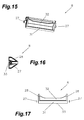
- an ink pad 4 is shown in which on one side an angular chamfer 115 / chamfer or bulge is arranged.
- the chamfer 115 extends from the narrow side surface 110 on the longitudinal side surface 106.
- an angled projection 116 corresponding to the chamfer 115 is arranged in the stamp 1 also on one side, in particular a side guide 103 or the surface 95.
- the projection 116 and the chamfer 115 have the same angle, so that when inserting the ink pad 4 in the stamp 1, these two surfaces come to rest or between the two surfaces only a very small distance is present.
- the chamfer / bevel or bulge 115 and the projection 116 is not formed as a flat angled surface, but that they are formed from a circle segment with corresponding radii corresponding or rectangular, that is, the chamfer 115 is formed semicircular, the can be inserted into a corresponding semicircular projection 116.
- the chamfer / chamfer or bulge 115 may also be composed of a plurality of surfaces or radii, etc. It is also possible that the surface is not formed 90 ° to the ink pad carrier 56, but this is preferably angled, so has a third dimension.
- stamp surface can still be used almost completely. It is also possible that on both sides of the stamp pad 4 and the receiving device 21 such chamfers 115 and projections 116 are formed, which may be designed the same or different.
- the chamfer / chamfer or bulge 115 extends over the entire width or thickness 100 of the stamp pad 4, wherein the protrusion 116 in the lower part 7 is designed accordingly or covers only a partial area.
- a corresponding knob in the form of a chamfer / chamfer or bulge 115 is formed or placed, for which purpose corresponding to the lower part 7 is provided.
- a cam system is shown.
- a cam 117 is arranged on the surface 95 of the lower part 7, which protrudes into the interior, in particular into the window 96, of the receiving device 21.
- a recess 118 is provided on the ink pad 4, which receives the cam 117 as possible without play.
- the cam 117 protrudes into the insert 51 of the stamp pad 4, ie, that upon mating of the punch 1 with the ink pad 4, the cam 117 is guided into the recess 118 and then presses directly into the insert 51, or in accordance trained insert 51 is arranged in a cavity of the insert 51.
- the direct immersion in the insert 51 ensures that the largest possible stamp imprint can be achieved because the insert below the cam 117 still exists and there can still be absorbed by the printing plate color, ie, that the stamp imprint up to the Edge is possible.
- the housing of the stamp pad 4 is formed such that in the region of the cam 117, a corresponding indentation is formed with a defined wall thickness, whereby immersion in the insert 51 is avoided.
- the cam 117 is preferably designed to be tapered, wherein the corresponding recess 118 has corresponding chamfers, so that the tapered cam 117 can be received as free of play as possible.
- the taper of the cam 117 further causes even more insert material below the cam 117 is present and thus the color absorption in the edge region is improved.
- the position of the arrangement of the cam 117 close to the region of the resilient means 74 on the surface 95 has proved to be advantageous insofar as a corresponding rigidity of the surface 95 is given in the edge region of the lower part 7 and thus the wall thickness does not need to be reinforced.
- the cam 117 between projection 90 and narrow side surface 110 is arranged.
- a ramp 119 is arranged on one or both side guides 103.
- a corresponding opening 120 is arranged on the narrow side face or faces 110, ie, for example, the housing of the stamp pad 4 is left correspondingly open in this area.
- the housing is naturally shaped so that the ramp 119 is received and laterally in the direction of insert 51 is formed according to a wall thickness.
- the measures provided in the stamp 1 means 74 for preventing the insertion of the ink pad 4 may also be resilient, ie, when inserting the ink pad 4, these means 74, such as the projections 90, bent or pushed away , so that in agreement the ink pad 4 can be used and that in turn when removing the ink pad 4 must be moved first, whereby the means 74 are again pushed away and then the ink pad 4 can be removed.
- the stamp 1 can be equipped with a turning mechanism of about 90 ° with a date.
- a turning mechanism of about 90 ° with a date.
- corresponding flaps or locking or slip protection can be used.
Landscapes
- Printing Methods (AREA)
- Manufacture Or Reproduction Of Printing Formes (AREA)
- Electric Connection Of Electric Components To Printed Circuits (AREA)
Applications Claiming Priority (3)
| Application Number | Priority Date | Filing Date | Title |
|---|---|---|---|
| AT7562011 | 2011-05-24 | ||
| ATA1733/2011A AT511453B1 (de) | 2011-05-24 | 2011-11-23 | Stempel und zugehöriges stempelkissen |
| EP12723613.1A EP2714410B1 (fr) | 2011-05-24 | 2012-05-21 | tampon e procédé pour monter une plaque de tampon |
Related Parent Applications (2)
| Application Number | Title | Priority Date | Filing Date |
|---|---|---|---|
| EP12723613.1A Division-Into EP2714410B1 (fr) | 2011-05-24 | 2012-05-21 | tampon e procédé pour monter une plaque de tampon |
| EP12723613.1A Division EP2714410B1 (fr) | 2011-05-24 | 2012-05-21 | tampon e procédé pour monter une plaque de tampon |
Publications (1)
| Publication Number | Publication Date |
|---|---|
| EP3067213A1 true EP3067213A1 (fr) | 2016-09-14 |
Family
ID=46168402
Family Applications (2)
| Application Number | Title | Priority Date | Filing Date |
|---|---|---|---|
| EP16164808.4A Withdrawn EP3067213A1 (fr) | 2011-05-24 | 2012-05-21 | Tampon encreur |
| EP12723613.1A Not-in-force EP2714410B1 (fr) | 2011-05-24 | 2012-05-21 | tampon e procédé pour monter une plaque de tampon |
Family Applications After (1)
| Application Number | Title | Priority Date | Filing Date |
|---|---|---|---|
| EP12723613.1A Not-in-force EP2714410B1 (fr) | 2011-05-24 | 2012-05-21 | tampon e procédé pour monter une plaque de tampon |
Country Status (8)
| Country | Link |
|---|---|
| US (2) | US9211754B2 (fr) |
| EP (2) | EP3067213A1 (fr) |
| CN (2) | CN104589817B (fr) |
| AT (1) | AT511453B1 (fr) |
| BR (1) | BR112013030004B1 (fr) |
| RU (1) | RU2562044C2 (fr) |
| TW (1) | TWI513599B (fr) |
| WO (1) | WO2012159728A2 (fr) |
Families Citing this family (13)
| Publication number | Priority date | Publication date | Assignee | Title |
|---|---|---|---|---|
| AT513901B1 (de) | 2013-01-24 | 2018-08-15 | Colop Stempelerzeugung Skopek Gmbh & Co Kg | Montagevorrichtung |
| AT513900B1 (de) * | 2013-01-24 | 2018-08-15 | Colop Stempelerzeugung Skopek Gmbh & Co Kg | Selbstfärbestempel |
| AT513897B1 (de) | 2013-01-24 | 2018-05-15 | Colop Stempelerzeugung Skopek Gmbh & Co Kg | Selbstfärbestempel mit einem Stempelgehäuse |
| AT513898B1 (de) | 2013-01-24 | 2019-01-15 | Colop Stempelerzeugung Skopek Gmbh & Co Kg | Einrichtung zum Führen eines Farbkissenbehälters sowie Selbstfärbestempel |
| WO2014113832A1 (fr) | 2013-01-24 | 2014-07-31 | Colop Stempelerzeugung Skopek Gesellschaft M.B.H. & Co. Kg. | Tampon auto-encreur |
| AT514243B1 (de) * | 2013-04-18 | 2024-03-15 | Trodat Gmbh | Selbstfärbender Stempel und Stempelkissen für den Stempel |
| US10300725B2 (en) * | 2016-07-05 | 2019-05-28 | Charles Bishop | Tally stamp devices, systems, and methods |
| AT518988B1 (de) * | 2016-09-30 | 2018-03-15 | Trodat Gmbh | Verfahren zum Erzeugen eines Stempelabdrucks mit UV-aushärtbarer Farbe mit |
| TWM587599U (zh) * | 2019-07-09 | 2019-12-11 | 三勝文具廠股份有限公司 | 改良型印台座 |
| CN110686965B (zh) * | 2019-10-11 | 2022-05-31 | 合肥工大共达工程检测试验有限公司 | 混凝土检测回弹法测区印章装置 |
| CN110614858A (zh) * | 2019-10-30 | 2019-12-27 | 杭州煜伟科技有限公司 | 一种防止油墨挥发自动翻转式印章 |
| CN111591023B (zh) * | 2020-05-06 | 2021-12-14 | 吉林省芭迪雅物流有限责任公司 | 一种大型物流快件自动标记设备 |
| CN114103495B (zh) * | 2021-10-28 | 2023-05-26 | 深圳市银之杰科技股份有限公司 | 室内和外出便携用印防印章偷盖的一体化方法和装置 |
Citations (8)
| Publication number | Priority date | Publication date | Assignee | Title |
|---|---|---|---|---|
| DE1276662B (de) | 1960-05-04 | 1968-09-05 | Hans Schnaeckel G M B H | Selbstfaerbestempel |
| EP0249901A2 (fr) | 1986-06-19 | 1987-12-23 | David Becher | Tampon auto-encreur en caoutchouc |
| EP0804344A1 (fr) * | 1994-12-01 | 1997-11-05 | Trodat-Werke Walter Just Gesellschaft m.b.H. & Co. KG | Appareil a tampon |
| US5740737A (en) | 1996-12-05 | 1998-04-21 | Identity Group, Inc. | Handstamping apparatus |
| AT409742B (de) * | 2001-01-25 | 2002-10-25 | Trodat Gmbh | Farbkissen für einen selbstfärbestempel |
| US6834584B1 (en) | 2003-09-03 | 2004-12-28 | M&R Marking Systems, Inc. | Pocket hand stamp |
| EP1507666B1 (fr) * | 2002-05-27 | 2005-10-12 | Trodat GmbH | Tampon et systeme de reception pour tampon encreur |
| AT503827B1 (de) | 2006-06-26 | 2008-08-15 | Trodat Gmbh | Stempel |
Family Cites Families (30)
| Publication number | Priority date | Publication date | Assignee | Title |
|---|---|---|---|---|
| US803372A (en) * | 1902-10-14 | 1905-10-31 | Helmer N Thune | Nail-driving machine. |
| US2884858A (en) * | 1957-06-03 | 1959-05-05 | Kwikmrk Inc | Self-inking hand stamp |
| AT232014B (de) * | 1960-05-04 | 1964-02-25 | Hans Schnaeckel G M B H | Selbstfärbestempel |
| US3973495A (en) * | 1970-07-31 | 1976-08-10 | Vuestamp International Proprietary Limited | Hand stamp |
| US4172419A (en) * | 1977-12-05 | 1979-10-30 | Munyon Gary D | Pre-linked stamp construction |
| US4432281A (en) * | 1982-03-10 | 1984-02-21 | M & R Seal Press Co., Inc. | Self-inking stamping device |
| AT375584B (de) * | 1983-02-04 | 1984-08-27 | Just Gmbh Walter | Selbstfaerbestempel mit oberschlagfaerbung |
| AT386382B (de) * | 1987-03-25 | 1988-08-10 | Just Gmbh Walter | Selbstfaerbestempel mit oberschlagfaerbung |
| US5359932A (en) * | 1992-09-21 | 1994-11-01 | Louis Melind Co. | Self-inking hand stamper with tilted inking pad |
| GB2293138B (en) * | 1994-08-09 | 1999-02-03 | Mark Universal Ltd | Pre-inked stamping device |
| EP0803372B1 (fr) * | 1996-04-22 | 1998-12-02 | M&R Marking Systems, Inc. | Tampon auto-encreur |
| JPH09300797A (ja) * | 1996-05-14 | 1997-11-25 | Brother Ind Ltd | スタンプ装置 |
| CN2253290Y (zh) * | 1996-06-13 | 1997-04-30 | 南开大学戈德防伪技术公司 | 防伪自供油印章 |
| JP4780850B2 (ja) * | 2001-04-23 | 2011-09-28 | シヤチハタ株式会社 | 印鑑ケース |
| US6829993B2 (en) * | 2001-11-09 | 2004-12-14 | Marc L. Aronson | Lock for a hand stamping device |
| JP3701244B2 (ja) * | 2002-01-07 | 2005-09-28 | 三菱鉛筆株式会社 | 印剤の担持体、それを用いた判子受け台及び印鑑フォルダー |
| AT7255U1 (de) * | 2002-05-27 | 2004-12-27 | Trodat Gmbh | Stempel und aufnahmeeinrichtung für ein stempelkissen |
| AT6731U1 (de) * | 2003-03-18 | 2004-03-25 | Colop Stempelerzeugung Skopek | Selbstfärbestempel mit oberschlagfärbung und farbkissen-behälter hiefür |
| US6945172B1 (en) * | 2004-06-10 | 2005-09-20 | Shiny Shih | Housing assembly for a self-inking stamp |
| US7011024B1 (en) * | 2004-09-10 | 2006-03-14 | Shiny Shih | Stamp die assembly for a self-inking stamping device |
| US7086331B2 (en) * | 2005-01-04 | 2006-08-08 | Cosco Industries, Inc. | Hand-held ink stamper with spare ink supply |
| AT7994U1 (de) * | 2005-01-24 | 2005-12-15 | Trodat Gmbh | Stempel mit haltevorrichtung für stempelkissentragvorrichtung |
| KR20060088323A (ko) * | 2005-02-01 | 2006-08-04 | 석태진 | 이중 도장 |
| AT9635U1 (de) * | 2006-10-11 | 2008-01-15 | Colop Stempelerzeugung Skopek | Farbspeichereinheit für einen handstempel |
| CN101293438A (zh) * | 2007-04-26 | 2008-10-29 | 昆山宝木产品设计有限公司 | 组合式印章盒 |
| US7761959B2 (en) * | 2007-11-30 | 2010-07-27 | Shiny Shih | Handle assembly for a stamp |
| AT507833A3 (de) * | 2009-01-30 | 2013-06-15 | Trodat Gmbh | Stempel und stempelkissen für einen selbst färbenden stempel |
| US20110179355A1 (en) * | 2010-01-15 | 2011-07-21 | Sony Ericsson Mobile Communications Ab | Virtual information input arrangement |
| AT513898B1 (de) * | 2013-01-24 | 2019-01-15 | Colop Stempelerzeugung Skopek Gmbh & Co Kg | Einrichtung zum Führen eines Farbkissenbehälters sowie Selbstfärbestempel |
| AT514243B1 (de) * | 2013-04-18 | 2024-03-15 | Trodat Gmbh | Selbstfärbender Stempel und Stempelkissen für den Stempel |
-
2011
- 2011-11-23 AT ATA1733/2011A patent/AT511453B1/de not_active IP Right Cessation
-
2012
- 2012-05-21 RU RU2013157190/12A patent/RU2562044C2/ru active
- 2012-05-21 BR BR112013030004-3A patent/BR112013030004B1/pt active IP Right Grant
- 2012-05-21 EP EP16164808.4A patent/EP3067213A1/fr not_active Withdrawn
- 2012-05-21 WO PCT/EP2012/002154 patent/WO2012159728A2/fr not_active Ceased
- 2012-05-21 EP EP12723613.1A patent/EP2714410B1/fr not_active Not-in-force
- 2012-05-24 US US13/479,866 patent/US9211754B2/en active Active
- 2012-05-24 TW TW101118609A patent/TWI513599B/zh active
- 2012-05-24 CN CN201510078774.0A patent/CN104589817B/zh active Active
- 2012-05-24 CN CN201210164589.XA patent/CN102795004B/zh active Active
-
2015
- 2015-11-23 US US14/949,443 patent/US11135864B2/en not_active Expired - Fee Related
Patent Citations (8)
| Publication number | Priority date | Publication date | Assignee | Title |
|---|---|---|---|---|
| DE1276662B (de) | 1960-05-04 | 1968-09-05 | Hans Schnaeckel G M B H | Selbstfaerbestempel |
| EP0249901A2 (fr) | 1986-06-19 | 1987-12-23 | David Becher | Tampon auto-encreur en caoutchouc |
| EP0804344A1 (fr) * | 1994-12-01 | 1997-11-05 | Trodat-Werke Walter Just Gesellschaft m.b.H. & Co. KG | Appareil a tampon |
| US5740737A (en) | 1996-12-05 | 1998-04-21 | Identity Group, Inc. | Handstamping apparatus |
| AT409742B (de) * | 2001-01-25 | 2002-10-25 | Trodat Gmbh | Farbkissen für einen selbstfärbestempel |
| EP1507666B1 (fr) * | 2002-05-27 | 2005-10-12 | Trodat GmbH | Tampon et systeme de reception pour tampon encreur |
| US6834584B1 (en) | 2003-09-03 | 2004-12-28 | M&R Marking Systems, Inc. | Pocket hand stamp |
| AT503827B1 (de) | 2006-06-26 | 2008-08-15 | Trodat Gmbh | Stempel |
Also Published As
| Publication number | Publication date |
|---|---|
| WO2012159728A2 (fr) | 2012-11-29 |
| BR112013030004A2 (pt) | 2016-09-13 |
| CN102795004B (zh) | 2015-04-01 |
| RU2562044C2 (ru) | 2015-09-10 |
| AT511453B1 (de) | 2012-12-15 |
| US20160152058A1 (en) | 2016-06-02 |
| CN104589817A (zh) | 2015-05-06 |
| US9211754B2 (en) | 2015-12-15 |
| RU2013157190A (ru) | 2015-06-27 |
| TWI513599B (zh) | 2015-12-21 |
| CN104589817B (zh) | 2018-03-30 |
| TW201307094A (zh) | 2013-02-16 |
| AT511453A4 (de) | 2012-12-15 |
| US20120297998A1 (en) | 2012-11-29 |
| EP2714410A2 (fr) | 2014-04-09 |
| CN102795004A (zh) | 2012-11-28 |
| EP2714410B1 (fr) | 2016-10-12 |
| BR112013030004B1 (pt) | 2020-12-15 |
| WO2012159728A3 (fr) | 2013-03-07 |
| US11135864B2 (en) | 2021-10-05 |
Similar Documents
| Publication | Publication Date | Title |
|---|---|---|
| EP2714410B1 (fr) | tampon e procédé pour monter une plaque de tampon | |
| EP2384283B1 (fr) | Timbre et tampon encreur pour un timbre autoencreur | |
| EP3307546B1 (fr) | Timbre, tampon encreur et capuchon de fermeture | |
| EP3498485B1 (fr) | Tampon | |
| EP3489024B1 (fr) | Tampon, en particulier tampon de trepied | |
| AT412772B (de) | Selbstfärbe-handstempel | |
| WO1995034731A1 (fr) | Systeme de fermeture, notamment pour automobiles et equipements de batiments | |
| DE3325878A1 (de) | Farbwalze fuer druckmaschinen | |
| EP1507666A1 (fr) | Tampon et systeme de reception pour tampon encreur | |
| EP2528743B1 (fr) | Unité de stockage d'encre pour un tampon manuel | |
| AT512968A1 (de) | Stempel, insbesondere Rund-Stempel | |
| AT7861U1 (de) | Handstempel, sowie abdeckung für handstempel | |
| AT514243A1 (de) | Selbstfärbender Stempel und Stempelkissen für den Stempel | |
| AT523250A1 (de) | Verschlusskappe für einen Stempel und Stempel hierfür | |
| AT518588B1 (de) | Kissenhalter | |
| DE102005044205A1 (de) | Selbstfärbestempel | |
| AT526894B1 (de) | Selbstfärbestempel und Verfahren zur Entnahme einer Wendeachse aus einem Selbstfärbestempel | |
| AT503424A4 (de) | Farbkissen für einen selbstfärbestempel | |
| AT502018B1 (de) | Selbstfärbestempel | |
| AT412545B (de) | Selbstfärbestempel | |
| AT412544B (de) | Stempel |
Legal Events
| Date | Code | Title | Description |
|---|---|---|---|
| PUAI | Public reference made under article 153(3) epc to a published international application that has entered the european phase |
Free format text: ORIGINAL CODE: 0009012 |
|
| AC | Divisional application: reference to earlier application |
Ref document number: 2714410 Country of ref document: EP Kind code of ref document: P |
|
| AK | Designated contracting states |
Kind code of ref document: A1 Designated state(s): AL AT BE BG CH CY CZ DE DK EE ES FI FR GB GR HR HU IE IS IT LI LT LU LV MC MK MT NL NO PL PT RO RS SE SI SK SM TR |
|
| 17P | Request for examination filed |
Effective date: 20170510 |
|
| RBV | Designated contracting states (corrected) |
Designated state(s): AL AT BE BG CH CY CZ DE DK EE ES FI FR GB GR HR HU IE IS IT LI LT LU LV MC MK MT NL NO PL PT RO RS SE SI SK SM TR |
|
| 17Q | First examination report despatched |
Effective date: 20180313 |
|
| STAA | Information on the status of an ep patent application or granted ep patent |
Free format text: STATUS: THE APPLICATION IS DEEMED TO BE WITHDRAWN |
|
| 18D | Application deemed to be withdrawn |
Effective date: 20180724 |