EP3067265B1 - Steuerungsanordnung einer internen Kupplung - Google Patents
Steuerungsanordnung einer internen Kupplung Download PDFInfo
- Publication number
- EP3067265B1 EP3067265B1 EP15159098.1A EP15159098A EP3067265B1 EP 3067265 B1 EP3067265 B1 EP 3067265B1 EP 15159098 A EP15159098 A EP 15159098A EP 3067265 B1 EP3067265 B1 EP 3067265B1
- Authority
- EP
- European Patent Office
- Prior art keywords
- claw
- control
- cam
- ring
- ratchet
- Prior art date
- Legal status (The legal status is an assumption and is not a legal conclusion. Google has not performed a legal analysis and makes no representation as to the accuracy of the status listed.)
- Active
Links
Images




Classifications
-
- B—PERFORMING OPERATIONS; TRANSPORTING
- B62—LAND VEHICLES FOR TRAVELLING OTHERWISE THAN ON RAILS
- B62M—RIDER PROPULSION OF WHEELED VEHICLES OR SLEDGES; POWERED PROPULSION OF SLEDGES OR SINGLE-TRACK CYCLES; TRANSMISSIONS SPECIALLY ADAPTED FOR SUCH VEHICLES
- B62M11/00—Transmissions characterised by the use of interengaging toothed wheels or frictionally-engaging wheels
- B62M11/04—Transmissions characterised by the use of interengaging toothed wheels or frictionally-engaging wheels of changeable ratio
- B62M11/14—Transmissions characterised by the use of interengaging toothed wheels or frictionally-engaging wheels of changeable ratio with planetary gears
- B62M11/16—Transmissions characterised by the use of interengaging toothed wheels or frictionally-engaging wheels of changeable ratio with planetary gears built in, or adjacent to, the ground-wheel hub
-
- B—PERFORMING OPERATIONS; TRANSPORTING
- B62—LAND VEHICLES FOR TRAVELLING OTHERWISE THAN ON RAILS
- B62M—RIDER PROPULSION OF WHEELED VEHICLES OR SLEDGES; POWERED PROPULSION OF SLEDGES OR SINGLE-TRACK CYCLES; TRANSMISSIONS SPECIALLY ADAPTED FOR SUCH VEHICLES
- B62M11/00—Transmissions characterised by the use of interengaging toothed wheels or frictionally-engaging wheels
- B62M11/04—Transmissions characterised by the use of interengaging toothed wheels or frictionally-engaging wheels of changeable ratio
- B62M11/14—Transmissions characterised by the use of interengaging toothed wheels or frictionally-engaging wheels of changeable ratio with planetary gears
Definitions
- the present invention relates to an internal clutch of a bike, and in particular to a control assembly of an internal clutch, wherein By power rotating components (such as input rings, inner gears planet frames, output rings, etc.) which rotates as the internal clutch and cam or cam-like component, clutching components are controlled. That is, using a cam or cam-like components to drive a driven device to rotate or displace so as to control the clutch to change gears.
- power rotating components such as input rings, inner gears planet frames, output rings, etc.
- the control mechanism of an internal clutch of a bicycle is complex and thus is heavy, large volume, and expensive. Meanwhile, it is insensitive in operation so as to deteriorate the quality of the clutch and the bicycle. Therefore, it is eager to develop and improve the prior art internal clutch of a bicycle.
- the present invention relates to bikes, and in particular to a control assembly of an internal clutch, in that the internal clutch is commonly used to chainless bikes and chain contained bikes; has the advantages of saving storage space, light weight, low cost, high usages in industry. Furthermore the structure of the internal clutch is simple so that the efficiencies in assembly and repair are promoted.
- power rotating components such as input rings, inner gears planet frames, output rings, etc.
- clutching components are controlled, such as to control the fixing of a sun gear, to control the engagements of the internal gear and planet gear. That is, using a cam or cam-like components to drive a driven device to rotate or displace so as to control the clutch to change gears
- a control assembly of an internal clutch comprising: a first control unit for controlling the fixedness of a sun gear; a second control unit for controlling engagements of inner gears at two sides and a planet frame; a third control unit for controlling the sun gear or the inner gears and the planet frame; and wherein power for control units are from rotary dynamic components, by displacements of driving rods for controlling operations of a cam or cam-like component; by using the cam or cam-like unit to function clutch or by using the cam or cam-like unit to drive a driven device to rotate or displace for operation of the clutch, characterized by the first control unit is an axial clutching control unit and further comprising: a center shaft having at least one guide recess for receiving a clutching driving rod; an actuating sliding seat installed outside the center shaft; a surface of the sliding seat being installed with a left gear, a ratchet ring and a right gear; the ratchet gear ring being installed between the left gear and the right gear; between the left gear
- control assembly of an internal clutch according to the present invention is illustrated.
- the control assembly includes a first control unit for controlling the fixedness of a sun gear; a second control unit for controlling the engagements of inner gears at two sides and a planet frame for locating a planet gear set; and a third control unit for widely controlling the sun gear or the inner gears and the planet frame.
- the main feature of the present invention is that the power of control units are mainly from rotary dynamic components of the clutch (such as input rings, inner gears, planet frames, output rings, etc.) by displacements of driving rods (including leftward and rightward displacements, upward and backward displacements, or angular displacements, etc.
- leftward and rightward displacements are used in the description of the present invention, but this is not used to confine the scope of the present invention) for controlling the operation of a cam or cam-like component).
- a cam or a cam-like unit is used to drive the clutch components or the cam or cam-like unit is used to drive a driven device to rotate or displace for operation a clutching device.
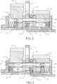
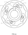
- Figs. 2 and 4 it shows an embodiment, where it determines that a sun gear is fixed to an axial clutching control unit or a radial clutching control unit.
- the structure is classified as an axial clutching form and a radial clutching form.
- Fig. 2 shows that a sun gear is fixed to or freely displacement with respect to the axial clutching control unit.
- Fig. 4 shows that a sun gear is fixed to or freely displacement with respect to the axial clutching control unit.
- the axial clutching control unit of the present invention includes the following elements.
- a center shaft 10 of the internal clutch 1 has at least one guide recess 101 for receiving a clutching driving rod.
- An actuating sliding seat 25 is installed outside the center shaft 10.
- a surface of the sliding seat 25 is installed with a left gear 28, a ratchet ring 2 and a right gear 29.
- the ratchet gear ring 2 is installed between the left gear 28 and the right gear 29.
- Between the left gear 28 and the center shaft 10 is installed with a left spring base 201, a left sliding block returning spring 27 and a left actuating sliding block 26 which is resisted by the sliding block returning spring 27 and is controlled by the cam base 24.
- Between the right gear 29 and the center shaft 10 is installed with a right spring base 202, a right sliding block returning spring 27' and a right actuating sliding block 26' which is resisted by the sliding block returning spring 27 and is controlled by the cam base 24.
- a cam base 24 is matched to the ratchet ring 2 and is installed with a first driving rod A. Movement of the cam base 24 will cause to drive one of a lift claw 22, a right claw 23 and a claw return spring 21.
- the driving rod A of the axial clutching unit is at a left side.
- the left gear 28 is fixed and the right gear 29 is freely rotatable.
- the left gear 28 is switched to be rotatable freely and the right gear 29 is switched to be fixed.
- the process is that: Firstly the driving rod A moves rightwards so that the left claw 22 is ejected upwards to engage to the ratchet ring 2 so as to drive the cam base 24 to rotate.
- the cam base 24 rotates, an axial cam pushes the left actuating sliding block 26 to leave from the left gear 28 so that the left gear 28 is free.
- the left sliding block returning spring 27 is compressed so that the left actuating sliding block 26 is ejected by the cam base 24 to move leftwards further.
- the cam base 24 rotates continuously so that the by the driving of the right sliding block returning spring 27', the right actuating sliding block 26' returns to right side. As a result, the right gear 29 is engaged with the right actuating sliding block 26'.
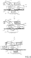
- a cross sectional view about the radial clutching unit of the present invention is illustrated.
- the main structure is like those described above, while the cam of the cam base 24 is radially moved.
- the left actuating sliding block 26 is changed to a left stop claw 261 and the right actuating sliding block 26' is changed to a right stop claw 261'.
- the left sliding returning spring 27 is changed to a left stop claw returning spring 271 and the right sliding returning spring 27' is changed to a right stop claw returning spring 271'.
- a left claw base 272 and a right claw base 273 are fixed to a surface of a center shaft 10.
- the operation of the stop claw 261 is identical to those illustrated in Fig. 5 and the operation principle is also like the above mentioned.
- the above mentioned control unit is performed by the fixedness of the sun gear. Since the fixedness of the ratchet ring 2 is by a rotation unit (such as an input ring, an inner gear, a planet frame, an output ring, etc. which rotates by changing gear).
- the function of the driving rod A serves to resist the claws 22, 23 not to engage with the ratchet ring 2. Therefore, it is not acted by input torque.
- the left claw 22 and the right claw 23 are paired (as a two pair structure illustrated in Fig. 4 ) so that a 90 degree rotation causes an action. Therefore, the action is sequentially proceeded by a step for each time.
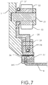
- Fig. 7 the control unit for the inner gears at two sides and the planet frame according to the present invention is illustrated.
- the control is classified as two kinds.
- the control claw is positioned at a linking device which is reacted with a power rotation unit.
- the control claw is positioned a fixing unit.
- Fig. 7 shows an embodiment that the control claw is positioned on a linking device.
- the control unit includes the following elements.
- a driving rod B, a control claw actuating seat 391 and a rotation ring 3 are installed at an outer side of a center shaft of an internal clutch.
- An inner side of the rotation ring 3 is installed with a claw shaft 31 for being assembled to an upper planet power clutching claw 32, a lower planet power clutching claw 33 and a clutching claw returning spring 34.
- a ratchet claw control panel 35 is installed below the ratchet claw.
- a controlling claw shaft 39 is used to control the left control claw 36 and a right control claw 37 and control the claw returning spring 38.
- the object of the control unit serves to control the closing of the upper planet power ratchet claw 32.
- the driving rod B is at left side, at this moment, the upper planet ratchet claw 32 opens and the right control claw 37 closes.
- the action for closing the upper planet power ratchet claw 32 is that: the driving rod B moves transversally from a position locating the left control claw 36 to a position locating the right control claw 37 (referring to Fig. 8 , the first and second steps). At this moment, the driving rod B does not support the left control claw 36 and is engaged with the control claw base 391 of the fixing unit. Therefore, the ratchet claw control panel 35 is fixed, even the ratchet claw control panel 35 rotates with respect to the rotation ring 3.
- Rotation of the ratchet claw control panel 35 causes the upper planet power ratchet claw 32 closes. Then the left control claw 36 leaves by the action of the rotation ring 3, while the right control claw 37 moves to a notch to be supported by the driving rod B.
- the third control unit has a control claw which is positioned on a fixing unit.
- a driving rod B, a control claw fixing base 40 are installed on outside of a center shaft of the internal clutch.
- a control claw shaft 401, a control claw returning spring 49, a left control claw 471 and a right control claw 481 are installed on the control claw fixing base 40.
- An upper planet power ratchet claw 42, a lower planet power ratchet claw 43 and a ratchet claw returning spring 44 are installed on the rotation claw 4.
- a ratchet claw control panel 45 is installed below the ratchet claw.
- a left limiting panel 47, a right limiting panel 48 and an auxiliary claw returning spring 461 are installed at two sides below the ratchet claw control panel 45.
- An auxiliary claw 46 is installed between the left control panel 47 and the rotation ring 4.
- the control claw fixing base 40 and the rotation ring 4 are at initial positions.
- the driving rod B is at a left side and the left control claw is supported by the driving rod B.
- the ratchet claw control panel 45 is not engaged.
- the right control claw 481 is stopped by the auxiliary claw 46 and the right limiting panel 48 and cannot engage the ratchet claw control panel 45. Therefore, the ratchet claw control panel 45 is motionless and has no function of changing speed.
- the driving rod B moves, it states to change speed. The operation is illustrated in Fig. 10 .
- the driving rod B moves rightwards, and thus the left control claw 471 does not engage to the ratchet claw control panel 45 so that the ratchet claw control claw 45 cannot rotate.
- the rotation ring 4 rotates continuously so that the ratchet claw control panel 45 to control the cam of the upper planet power ratchet claw 42 to move leftwards. Therefore, the upper planet power ratchet claw 42 closes and to leave from the upper planet power ratchet claw 42.
- FIG. 11 shows a control unit which is widely used to a radial clutching and axial clutching operation.
- a driving rod C, a radial control cam ring 55, an axial control cam ring 56 are installed on an outer side of a center shaft of the internal clutch.
- a spacing ring 57 is installed between the radial control cam ring 55 and the axial control cam ring 56.
- a power rotation unit 5 is installed with a sliding ring 51 which is used as a linking device.
- An axial spring 52 is installed between an outer side of the sliding ring 51 and the rotation unit 5.
- An interior of the sliding ring 51 is installed with a pin 54 and a radial spring 53.
- clutching components are controlled, such as to control the fixing of a sun gear, to control the engagements of the internal gear and planet gear. That is, using a cam or cam-like components to drive a driven device to rotate or displace so as to control the clutch to change gears
Landscapes
- Engineering & Computer Science (AREA)
- Chemical & Material Sciences (AREA)
- Combustion & Propulsion (AREA)
- Transportation (AREA)
- Mechanical Engineering (AREA)
- One-Way And Automatic Clutches, And Combinations Of Different Clutches (AREA)
Claims (8)
- Steuerungsanordnung einer internen Kupplung, die Folgendes umfasst:eine erste Steuereinheit (A) zum Steuern der Fixiertheit eines Sonnenrads (28, 29);eine zweite Steuereinheit (B) zum Steuern der Eingriffe von inneren Zahnrädern auf zwei Seiten und eines Planetenrahmens;eine dritte Steuereinheit (C) zum Steuern des Sonnenrads oder der inneren Zahnräder und des Planetenrahmens; undwobei Kraft für Steuereinheiten von drehenden dynamischen Komponenten herrührt, durch Verschiebungen von Antriebsstangen zum Steuern von Vorgängen eines Nockens oder einer nockenartigen Komponente; durch Verwenden des Nockens oder der nockenartigen Einheit zum Betätigen der Kupplung oder durch Verwenden des Nockens oder der nockenartigen Einheit zum Antreiben einer angetriebenen Vorrichtung zum Drehen oder Verschieben zum Betätigen der Kupplung, dadurch gekennzeichnet, dass es sich bei der ersten Steuereinheit um eine axiale Kupplungssteuereinheit handelt, und weiter umfassend:eine mittlere Achse (10) mit mindestens einer Führungsaussparung zum Aufnehmen einer Kupplungsantriebsstange (A);einen Betätigungs-Gleitsitz (25), der außerhalb der mittleren Achse (10) installiert ist; wobei eine Oberfläche des Gleitsitzes (25) mit einem linken Zahnrad (28), einem Ratschenhohlrad (2) und einem rechten Zahnrad (29) installiert ist; wobei das Ratschenhohlrad (2) zwischen dem linken Zahnrad (28) und dem rechten Zahnrad (29) installiert ist;wobei zwischen dem linken Zahnrad (28) und der mittleren Achse (10) eine linke Federbasis (201), eine linke Gleitklotz-Rückstellfeder (27) und ein linker Betätigungs-Gleitklotz (26), dem von der Gleitklotz-Rückstellfeder (27) widerstanden wird und der von der Nockenbasis (24) gesteuert wird, installiert sind; undwobei zwischen dem rechten Zahnrad (29) und der mittleren Achse (10) eine rechte Federbasis (202), eine rechte Gleitklotz-Rückstellfeder (27') und ein rechter Betätigungs-Gleitklotz (26'), dem von der Gleitklotz-Rückstellfeder (27) widerstanden wird und der von der Nockenbasis (24) gesteuert wird, installiert sind.
- Steuerungsanordnung einer internen Kupplung, die Folgendes umfasst:eine erste Steuereinheit (A) zum Steuern der Fixiertheit eines Sonnenrads (28, 29);eine zweite Steuereinheit (B) zum Steuern der Eingriffe von inneren Zahnrädern auf zwei Seiten und eines Planetenrahmens;eine dritte Steuereinheit (C) zum Steuern des Sonnenrads oder der inneren Zahnräder und des Planetenrahmens; undwobei Kraft für Steuereinheiten von drehenden dynamischen Komponenten herrührt, durch Verschiebungen von Antriebsstangen zum Steuern von Vorgängen eines Nockens oder einer nockenartigen Komponente; durch Verwenden des Nockens oder der nockenartigen Einheit zum Betätigen der Kupplung oder durch Verwenden des Nockens oder der nockenartigen Einheit zum Antreiben einer angetriebenen Vorrichtung zum Drehen oder Verschieben zum Betätigen der Kupplung, dadurch gekennzeichnet, dass es sich bei der ersten Steuereinheit um eine axiale Kupplungssteuereinheit handelt, und weiter umfassend:eine mittlere Achse (10) mit mindestens einer Führungsaussparung zum Aufnehmen einer Kupplungsantriebsstange (A);einen Betätigungs-Gleitsitz, der außerhalb der mittleren Achse installiert ist; wobei eine Oberfläche des Gleitsitzes mit einem linken Zahnrad (28), einem Ratschenhohlrad (2) und einem rechten Zahnrad (29) installiert ist; wobei das Ratschenhohlrad (2) zwischen dem linken Zahnrad (28) und dem rechten Zahnrad (29) installiert ist;wobei zwischen dem linken Zahnrad (28) und der mittleren Achse (10) eine linke Federbasis (201), eine linke Sperrklauen-Rückstellfeder (271) und eine linke Sperrklaue (26), der von der Sperrklauen-Rückstellfeder widerstanden wird und die von der Nockenbasis (24) gesteuert wird, installiert sind; undwobei zwischen dem rechten Zahnrad (29) und der mittleren Achse (10) eine rechte Federbasis (202), eine rechte Sperrklauen-Rückstellfeder (271') und eine rechte Sperrklaue (261'), der von der Sperrklauen-Rückstellfeder widerstanden wird und die von der Nockenbasis (24) gesteuert wird, installiert sind; undeine linke Klauenbasis (272) und eine rechte Klauenbasis (273), die an der Oberfläche einer mittleren Achsen (10) befestigt sind.
- Steuerungsanordnung einer internen Kupplung nach Anspruch 1 oder 2, wobei es sich bei der Verschiebung der Antriebsstange um eine von einer Verschiebung in Querrichtung, einer vertikalen Verschiebung und einer Winkelverschiebung handelt.
- Steuerungsanordnung einer internen Kupplung nach Anspruch 1 oder 2, wobei die zweite Steuereinheit dazu dient, das Öffnen oder Schließen einer Ratschenklaue an dem Planetenrahmen zu steuern; und die zweite Steuereinheit die Ratschenklaue zu einer Drehkopplungsvorrichtung oder zum Steuern der Ratschenklaue zu einer feststehenden Vorrichtung steuert.
- Steuerungsanordnung einer internen Kupplung nach Anspruch 4, wobei dazu, dass die zweite Steuereinheit die Ratschenklaue zu einer Drehkopplungsvorrichtung steuert, die zweite Steuereinheit Folgendes umfasst:eine Antriebsstange (B);einen Steuerklauen-Betätigungssitz (391) und einen Drehring (3), die an einer Außenseite einer mittleren Achse (10) einer internen Kupplung installiert sind; undwobei eine Innenseite des Drehrings (3) mit einer Klauenachse (31) zur Montage an einer oberen Planetenkraft-Kupplungsklaue (32), einer unteren Planetenkraft-Kupplungsklaue (33) und einer Kupplungsklauen-Rückstellfeder (34) installiert ist; undwobei eine Ratschenklauen-Steuerplatte (35) unter der Ratschenklaue installiert ist; wobei eine Steuerklauenachse (39) verwendet wird, um die linke Steuerklaue (36) und eine rechte Steuerklaue (37) zu steuern und die Klauen-Rückstellfeder (38) zu steuern.
- Steuerungsanordnung einer internen Kupplung nach Anspruch 4, wobei dazu, dass die zweite Steuereinheit die Ratschenklaue dazu steuert, auf einer Fixierungseinheit positioniert zu werden, die zweite Steuereinheit Folgendes umfasst:eine Antriebsstange (B);eine Steuerklauen-Fixierungsbasis (40), die auf dem Äußeren einer mittleren Achse (10) der internen Kupplung (1) installiert ist;eine Steuerklauenachse (401), eine Steuerklauen-Rückstellfeder (49), eine linke Steuerklaue (471) und eine rechte Steuerklaue (481), die auf der Steuerklauen-Befestigungsbasis (40) installiert sind;eine obere Planetenkraft-Ratschenklaue (42), eine untere Planetenkraft-Ratschenklaue (43) und eine Ratschenklauen-Rückstellfeder (44), die an der Drehklaue (4) installiert sind;eine Ratschenklauen-Steuerplatte (45), die unter der Ratschenklaue installiert ist;eine linke Begrenzungsplatte (47), eine rechte Begrenzungsplatte (48) und eine Hilfsklauen-Rückstellfeder (461), die auf zwei Seiten unter der Ratschenklauen-Steuerplatte (45) installiert sind; undeine Hilfsklaue (46), die zwischen der linken Steuerplatte (47) und dem Drehring (4) installiert ist.
- Steuerungsanordnung für eine interne Kupplung nach Anspruch 4, wobei die dritte Steuereinheit Folgendes umfasst:eine dritte Antriebsstange (C), einen Radialsteuernockenring (55), einen Axialsteuernockenring (56), die an einer Außenseite einer mittleren Achse der internen Kupplung installiert sind;einen Distanzring (57), der zwischen dem Radialsteuernockenring (55) und dem Axialsteuernockenring (56) installiert ist;eine Kraftdreheinheit (5), die mit einem Gleitring (51) installiert ist, der als Kopplungsvorrichtung verwendet wird;eine Axialfeder (52), die zwischen einer Außenseite des Gleitrings (51) und der Dreheinheit (5) installiert ist; wobei ein Inneres des Gleitrings (51) mit einem Stift (54) und einer Radialfeder (53) installiert ist.
- Steuerungsanordnung einer internen Kupplung nach Anspruch 7, wobei durch die Verschiebung des Gleitrings (51) der Stift (54) bewegt wird, um an dem Radialsteuernockenring (55) oder an dem Axialsteuernockenring (56) gehalten zu werden, um die Aufgabe des radialen oder axialen Kuppelns zu erfüllen.
Priority Applications (2)
| Application Number | Priority Date | Filing Date | Title |
|---|---|---|---|
| EP15159098.1A EP3067265B1 (de) | 2015-03-13 | 2015-03-13 | Steuerungsanordnung einer internen Kupplung |
| DK15159098.1T DK3067265T3 (da) | 2015-03-13 | 2015-03-13 | Styreindretning til en indre kobling |
Applications Claiming Priority (1)
| Application Number | Priority Date | Filing Date | Title |
|---|---|---|---|
| EP15159098.1A EP3067265B1 (de) | 2015-03-13 | 2015-03-13 | Steuerungsanordnung einer internen Kupplung |
Publications (2)
| Publication Number | Publication Date |
|---|---|
| EP3067265A1 EP3067265A1 (de) | 2016-09-14 |
| EP3067265B1 true EP3067265B1 (de) | 2019-11-20 |
Family
ID=52669538
Family Applications (1)
| Application Number | Title | Priority Date | Filing Date |
|---|---|---|---|
| EP15159098.1A Active EP3067265B1 (de) | 2015-03-13 | 2015-03-13 | Steuerungsanordnung einer internen Kupplung |
Country Status (2)
| Country | Link |
|---|---|
| EP (1) | EP3067265B1 (de) |
| DK (1) | DK3067265T3 (de) |
Families Citing this family (1)
| Publication number | Priority date | Publication date | Assignee | Title |
|---|---|---|---|---|
| CN106931053A (zh) * | 2017-04-18 | 2017-07-07 | 郭克亚 | 一种楔块式离合器 |
Family Cites Families (6)
| Publication number | Priority date | Publication date | Assignee | Title |
|---|---|---|---|---|
| JP3157205B2 (ja) * | 1991-09-09 | 2001-04-16 | 株式会社シマノ | 自転車用変速装置 |
| DE9303507U1 (de) * | 1993-03-10 | 1993-06-09 | Fichtel & Sachs Ag, 8720 Schweinfurt | Mehrgang-Antriebsnabe für Fahrräder |
| DE4415266C1 (de) * | 1994-04-30 | 1995-08-10 | Fichtel & Sachs Ag | Schalteinrichtung für ein Wechselgetriebe in Mehrgangnaben für Fahrräder |
| JP2983173B2 (ja) * | 1996-04-22 | 1999-11-29 | 株式会社シマノ | 内装ハブ |
| US6267704B1 (en) * | 1999-03-18 | 2001-07-31 | Sram Corporation | Servo Three-speed planetary hub |
| EP1172291A1 (de) * | 2000-07-11 | 2002-01-16 | Jen-Chih Liu | Schaltbare Zweiradnabe mit zweifach betätigter, integrierter Bremse |
-
2015
- 2015-03-13 EP EP15159098.1A patent/EP3067265B1/de active Active
- 2015-03-13 DK DK15159098.1T patent/DK3067265T3/da active
Non-Patent Citations (1)
| Title |
|---|
| None * |
Also Published As
| Publication number | Publication date |
|---|---|
| DK3067265T3 (da) | 2020-02-24 |
| EP3067265A1 (de) | 2016-09-14 |
Similar Documents
| Publication | Publication Date | Title |
|---|---|---|
| US20160305496A1 (en) | Control assembly of an internal clutch | |
| EP2388497A1 (de) | Parkmechanismus für Getriebe | |
| US9574638B2 (en) | Transmission for vehicle | |
| CN105090393B (zh) | 六换档元件阶梯传动比自动变速器 | |
| EP3650329B1 (de) | Nabengetriebe | |
| US20150192193A1 (en) | Vehicular power transmission device | |
| US20220221012A1 (en) | Interior clutch-used control mechanism | |
| EP2693084A1 (de) | Getriebe | |
| JP4594840B2 (ja) | トラクタの変速伝動装置 | |
| EP4337519B1 (de) | Pedalgetriebenes mehrganggetriebesystem | |
| CN106051152A (zh) | 一种用于自动变速器的驻车及换档执行机构 | |
| US20190242459A1 (en) | Control assembly of an internal clutch | |
| EP3067265A1 (de) | Steuerungsanordnung einer internen Kupplung | |
| US20220205494A1 (en) | Interior clutch-used control mechanism | |
| KR101649880B1 (ko) | 자동변속기의 멀티 모드 클러치 모듈 | |
| US20220034373A1 (en) | Interior clutch-used control mechanism | |
| KR101467058B1 (ko) | 변속 시 토크 드롭이 방지된 변속장치 | |
| CN102840323A (zh) | 用于变速器的操纵模块 | |
| US20220213938A1 (en) | Interior clutch-used control mechanism | |
| CN205618576U (zh) | 一种三位双向可控的超越离合器 | |
| WO2016028207A1 (en) | Transmission for vehicle, vehicle comprising such a transmission and method to control a transmission | |
| JP6227587B2 (ja) | 内装変速機の制御装置 | |
| KR20150029223A (ko) | 무한 변속기 | |
| US10041567B2 (en) | Driving control system of internal clutch | |
| CN106476979B (zh) | 一种可实现快速启动的自行车双轮驱动装置 |
Legal Events
| Date | Code | Title | Description |
|---|---|---|---|
| PUAI | Public reference made under article 153(3) epc to a published international application that has entered the european phase |
Free format text: ORIGINAL CODE: 0009012 |
|
| AK | Designated contracting states |
Kind code of ref document: A1 Designated state(s): AL AT BE BG CH CY CZ DE DK EE ES FI FR GB GR HR HU IE IS IT LI LT LU LV MC MK MT NL NO PL PT RO RS SE SI SK SM TR |
|
| AX | Request for extension of the european patent |
Extension state: BA ME |
|
| STAA | Information on the status of an ep patent application or granted ep patent |
Free format text: STATUS: REQUEST FOR EXAMINATION WAS MADE |
|
| 17P | Request for examination filed |
Effective date: 20170314 |
|
| RBV | Designated contracting states (corrected) |
Designated state(s): AL AT BE BG CH CY CZ DE DK EE ES FI FR GB GR HR HU IE IS IT LI LT LU LV MC MK MT NL NO PL PT RO RS SE SI SK SM TR |
|
| GRAP | Despatch of communication of intention to grant a patent |
Free format text: ORIGINAL CODE: EPIDOSNIGR1 |
|
| STAA | Information on the status of an ep patent application or granted ep patent |
Free format text: STATUS: GRANT OF PATENT IS INTENDED |
|
| INTG | Intention to grant announced |
Effective date: 20190606 |
|
| GRAA | (expected) grant |
Free format text: ORIGINAL CODE: 0009210 |
|
| STAA | Information on the status of an ep patent application or granted ep patent |
Free format text: STATUS: THE PATENT HAS BEEN GRANTED |
|
| GRAS | Grant fee paid |
Free format text: ORIGINAL CODE: EPIDOSNIGR3 |
|
| AK | Designated contracting states |
Kind code of ref document: B1 Designated state(s): AL AT BE BG CH CY CZ DE DK EE ES FI FR GB GR HR HU IE IS IT LI LT LU LV MC MK MT NL NO PL PT RO RS SE SI SK SM TR |
|
| REG | Reference to a national code |
Ref country code: GB Ref legal event code: FG4D |
|
| REG | Reference to a national code |
Ref country code: CH Ref legal event code: EP |
|
| REG | Reference to a national code |
Ref country code: IE Ref legal event code: FG4D |
|
| REG | Reference to a national code |
Ref country code: DE Ref legal event code: R096 Ref document number: 602015041898 Country of ref document: DE |
|
| REG | Reference to a national code |
Ref country code: AT Ref legal event code: REF Ref document number: 1203888 Country of ref document: AT Kind code of ref document: T Effective date: 20191215 |
|
| REG | Reference to a national code |
Ref country code: NL Ref legal event code: FP |
|
| REG | Reference to a national code |
Ref country code: DK Ref legal event code: T3 Effective date: 20200219 |
|
| REG | Reference to a national code |
Ref country code: LT Ref legal event code: MG4D |
|
| PG25 | Lapsed in a contracting state [announced via postgrant information from national office to epo] |
Ref country code: FI Free format text: LAPSE BECAUSE OF FAILURE TO SUBMIT A TRANSLATION OF THE DESCRIPTION OR TO PAY THE FEE WITHIN THE PRESCRIBED TIME-LIMIT Effective date: 20191120 Ref country code: BG Free format text: LAPSE BECAUSE OF FAILURE TO SUBMIT A TRANSLATION OF THE DESCRIPTION OR TO PAY THE FEE WITHIN THE PRESCRIBED TIME-LIMIT Effective date: 20200220 Ref country code: GR Free format text: LAPSE BECAUSE OF FAILURE TO SUBMIT A TRANSLATION OF THE DESCRIPTION OR TO PAY THE FEE WITHIN THE PRESCRIBED TIME-LIMIT Effective date: 20200221 Ref country code: NO Free format text: LAPSE BECAUSE OF FAILURE TO SUBMIT A TRANSLATION OF THE DESCRIPTION OR TO PAY THE FEE WITHIN THE PRESCRIBED TIME-LIMIT Effective date: 20200220 Ref country code: LV Free format text: LAPSE BECAUSE OF FAILURE TO SUBMIT A TRANSLATION OF THE DESCRIPTION OR TO PAY THE FEE WITHIN THE PRESCRIBED TIME-LIMIT Effective date: 20191120 Ref country code: SE Free format text: LAPSE BECAUSE OF FAILURE TO SUBMIT A TRANSLATION OF THE DESCRIPTION OR TO PAY THE FEE WITHIN THE PRESCRIBED TIME-LIMIT Effective date: 20191120 Ref country code: LT Free format text: LAPSE BECAUSE OF FAILURE TO SUBMIT A TRANSLATION OF THE DESCRIPTION OR TO PAY THE FEE WITHIN THE PRESCRIBED TIME-LIMIT Effective date: 20191120 |
|
| PG25 | Lapsed in a contracting state [announced via postgrant information from national office to epo] |
Ref country code: IS Free format text: LAPSE BECAUSE OF FAILURE TO SUBMIT A TRANSLATION OF THE DESCRIPTION OR TO PAY THE FEE WITHIN THE PRESCRIBED TIME-LIMIT Effective date: 20200320 Ref country code: RS Free format text: LAPSE BECAUSE OF FAILURE TO SUBMIT A TRANSLATION OF THE DESCRIPTION OR TO PAY THE FEE WITHIN THE PRESCRIBED TIME-LIMIT Effective date: 20191120 Ref country code: HR Free format text: LAPSE BECAUSE OF FAILURE TO SUBMIT A TRANSLATION OF THE DESCRIPTION OR TO PAY THE FEE WITHIN THE PRESCRIBED TIME-LIMIT Effective date: 20191120 |
|
| PG25 | Lapsed in a contracting state [announced via postgrant information from national office to epo] |
Ref country code: AL Free format text: LAPSE BECAUSE OF FAILURE TO SUBMIT A TRANSLATION OF THE DESCRIPTION OR TO PAY THE FEE WITHIN THE PRESCRIBED TIME-LIMIT Effective date: 20191120 |
|
| PG25 | Lapsed in a contracting state [announced via postgrant information from national office to epo] |
Ref country code: ES Free format text: LAPSE BECAUSE OF FAILURE TO SUBMIT A TRANSLATION OF THE DESCRIPTION OR TO PAY THE FEE WITHIN THE PRESCRIBED TIME-LIMIT Effective date: 20191120 Ref country code: EE Free format text: LAPSE BECAUSE OF FAILURE TO SUBMIT A TRANSLATION OF THE DESCRIPTION OR TO PAY THE FEE WITHIN THE PRESCRIBED TIME-LIMIT Effective date: 20191120 Ref country code: PT Free format text: LAPSE BECAUSE OF FAILURE TO SUBMIT A TRANSLATION OF THE DESCRIPTION OR TO PAY THE FEE WITHIN THE PRESCRIBED TIME-LIMIT Effective date: 20200412 Ref country code: RO Free format text: LAPSE BECAUSE OF FAILURE TO SUBMIT A TRANSLATION OF THE DESCRIPTION OR TO PAY THE FEE WITHIN THE PRESCRIBED TIME-LIMIT Effective date: 20191120 Ref country code: CZ Free format text: LAPSE BECAUSE OF FAILURE TO SUBMIT A TRANSLATION OF THE DESCRIPTION OR TO PAY THE FEE WITHIN THE PRESCRIBED TIME-LIMIT Effective date: 20191120 |
|
| REG | Reference to a national code |
Ref country code: AT Ref legal event code: MK05 Ref document number: 1203888 Country of ref document: AT Kind code of ref document: T Effective date: 20191120 |
|
| REG | Reference to a national code |
Ref country code: DE Ref legal event code: R097 Ref document number: 602015041898 Country of ref document: DE |
|
| PG25 | Lapsed in a contracting state [announced via postgrant information from national office to epo] |
Ref country code: SM Free format text: LAPSE BECAUSE OF FAILURE TO SUBMIT A TRANSLATION OF THE DESCRIPTION OR TO PAY THE FEE WITHIN THE PRESCRIBED TIME-LIMIT Effective date: 20191120 Ref country code: SK Free format text: LAPSE BECAUSE OF FAILURE TO SUBMIT A TRANSLATION OF THE DESCRIPTION OR TO PAY THE FEE WITHIN THE PRESCRIBED TIME-LIMIT Effective date: 20191120 |
|
| PLBE | No opposition filed within time limit |
Free format text: ORIGINAL CODE: 0009261 |
|
| STAA | Information on the status of an ep patent application or granted ep patent |
Free format text: STATUS: NO OPPOSITION FILED WITHIN TIME LIMIT |
|
| 26N | No opposition filed |
Effective date: 20200821 |
|
| PG25 | Lapsed in a contracting state [announced via postgrant information from national office to epo] |
Ref country code: MC Free format text: LAPSE BECAUSE OF FAILURE TO SUBMIT A TRANSLATION OF THE DESCRIPTION OR TO PAY THE FEE WITHIN THE PRESCRIBED TIME-LIMIT Effective date: 20191120 |
|
| REG | Reference to a national code |
Ref country code: CH Ref legal event code: PL |
|
| PG25 | Lapsed in a contracting state [announced via postgrant information from national office to epo] |
Ref country code: PL Free format text: LAPSE BECAUSE OF FAILURE TO SUBMIT A TRANSLATION OF THE DESCRIPTION OR TO PAY THE FEE WITHIN THE PRESCRIBED TIME-LIMIT Effective date: 20191120 Ref country code: AT Free format text: LAPSE BECAUSE OF FAILURE TO SUBMIT A TRANSLATION OF THE DESCRIPTION OR TO PAY THE FEE WITHIN THE PRESCRIBED TIME-LIMIT Effective date: 20191120 Ref country code: SI Free format text: LAPSE BECAUSE OF FAILURE TO SUBMIT A TRANSLATION OF THE DESCRIPTION OR TO PAY THE FEE WITHIN THE PRESCRIBED TIME-LIMIT Effective date: 20191120 |
|
| REG | Reference to a national code |
Ref country code: BE Ref legal event code: MM Effective date: 20200331 |
|
| PG25 | Lapsed in a contracting state [announced via postgrant information from national office to epo] |
Ref country code: LU Free format text: LAPSE BECAUSE OF NON-PAYMENT OF DUE FEES Effective date: 20200313 |
|
| PG25 | Lapsed in a contracting state [announced via postgrant information from national office to epo] |
Ref country code: LI Free format text: LAPSE BECAUSE OF NON-PAYMENT OF DUE FEES Effective date: 20200331 Ref country code: CH Free format text: LAPSE BECAUSE OF NON-PAYMENT OF DUE FEES Effective date: 20200331 Ref country code: IE Free format text: LAPSE BECAUSE OF NON-PAYMENT OF DUE FEES Effective date: 20200313 |
|
| PG25 | Lapsed in a contracting state [announced via postgrant information from national office to epo] |
Ref country code: BE Free format text: LAPSE BECAUSE OF NON-PAYMENT OF DUE FEES Effective date: 20200331 |
|
| PG25 | Lapsed in a contracting state [announced via postgrant information from national office to epo] |
Ref country code: TR Free format text: LAPSE BECAUSE OF FAILURE TO SUBMIT A TRANSLATION OF THE DESCRIPTION OR TO PAY THE FEE WITHIN THE PRESCRIBED TIME-LIMIT Effective date: 20191120 Ref country code: MT Free format text: LAPSE BECAUSE OF FAILURE TO SUBMIT A TRANSLATION OF THE DESCRIPTION OR TO PAY THE FEE WITHIN THE PRESCRIBED TIME-LIMIT Effective date: 20191120 Ref country code: CY Free format text: LAPSE BECAUSE OF FAILURE TO SUBMIT A TRANSLATION OF THE DESCRIPTION OR TO PAY THE FEE WITHIN THE PRESCRIBED TIME-LIMIT Effective date: 20191120 |
|
| PG25 | Lapsed in a contracting state [announced via postgrant information from national office to epo] |
Ref country code: MK Free format text: LAPSE BECAUSE OF FAILURE TO SUBMIT A TRANSLATION OF THE DESCRIPTION OR TO PAY THE FEE WITHIN THE PRESCRIBED TIME-LIMIT Effective date: 20191120 |
|
| PGFP | Annual fee paid to national office [announced via postgrant information from national office to epo] |
Ref country code: IT Payment date: 20250226 Year of fee payment: 11 |
|
| PGFP | Annual fee paid to national office [announced via postgrant information from national office to epo] |
Ref country code: GB Payment date: 20260324 Year of fee payment: 12 |
|
| PGFP | Annual fee paid to national office [announced via postgrant information from national office to epo] |
Ref country code: DE Payment date: 20260310 Year of fee payment: 12 Ref country code: DK Payment date: 20260326 Year of fee payment: 12 |
|
| PGFP | Annual fee paid to national office [announced via postgrant information from national office to epo] |
Ref country code: NL Payment date: 20260317 Year of fee payment: 12 |
|
| PGFP | Annual fee paid to national office [announced via postgrant information from national office to epo] |
Ref country code: FR Payment date: 20260323 Year of fee payment: 12 |