EP3067310B1 - Appareil de remplacement d'une chambre de combustion de turbine à gaz et procédé - Google Patents
Appareil de remplacement d'une chambre de combustion de turbine à gaz et procédé Download PDFInfo
- Publication number
- EP3067310B1 EP3067310B1 EP15158898.5A EP15158898A EP3067310B1 EP 3067310 B1 EP3067310 B1 EP 3067310B1 EP 15158898 A EP15158898 A EP 15158898A EP 3067310 B1 EP3067310 B1 EP 3067310B1
- Authority
- EP
- European Patent Office
- Prior art keywords
- carriage
- combustor
- motion
- turbine part
- sledge
- Prior art date
- Legal status (The legal status is an assumption and is not a legal conclusion. Google has not performed a legal analysis and makes no representation as to the accuracy of the status listed.)
- Active
Links
Images





Classifications
-
- B—PERFORMING OPERATIONS; TRANSPORTING
- B23—MACHINE TOOLS; METAL-WORKING NOT OTHERWISE PROVIDED FOR
- B23P—METAL-WORKING NOT OTHERWISE PROVIDED FOR; COMBINED OPERATIONS; UNIVERSAL MACHINE TOOLS
- B23P19/00—Machines for simply fitting together or separating metal parts or objects, or metal and non-metal parts, whether or not involving some deformation; Tools or devices therefor so far as not provided for in other classes
- B23P19/04—Machines for simply fitting together or separating metal parts or objects, or metal and non-metal parts, whether or not involving some deformation; Tools or devices therefor so far as not provided for in other classes for assembling or disassembling parts
- B23P19/042—Machines for simply fitting together or separating metal parts or objects, or metal and non-metal parts, whether or not involving some deformation; Tools or devices therefor so far as not provided for in other classes for assembling or disassembling parts specially adapted for combustion engines
-
- F—MECHANICAL ENGINEERING; LIGHTING; HEATING; WEAPONS; BLASTING
- F02—COMBUSTION ENGINES; HOT-GAS OR COMBUSTION-PRODUCT ENGINE PLANTS
- F02C—GAS-TURBINE PLANTS; AIR INTAKES FOR JET-PROPULSION PLANTS; CONTROLLING FUEL SUPPLY IN AIR-BREATHING JET-PROPULSION PLANTS
- F02C7/00—Features, components parts, details or accessories, not provided for in, or of interest apart form groups F02C1/00 - F02C6/00; Air intakes for jet-propulsion plants
- F02C7/20—Mounting or supporting of plant; Accommodating heat expansion or creep
-
- F—MECHANICAL ENGINEERING; LIGHTING; HEATING; WEAPONS; BLASTING
- F01—MACHINES OR ENGINES IN GENERAL; ENGINE PLANTS IN GENERAL; STEAM ENGINES
- F01D—NON-POSITIVE DISPLACEMENT MACHINES OR ENGINES, e.g. STEAM TURBINES
- F01D25/00—Component parts, details, or accessories, not provided for in, or of interest apart from, other groups
- F01D25/28—Supporting or mounting arrangements, e.g. for turbine casing
- F01D25/285—Temporary support structures, e.g. for testing, assembling, installing, repairing; Assembly methods using such structures
-
- F—MECHANICAL ENGINEERING; LIGHTING; HEATING; WEAPONS; BLASTING
- F01—MACHINES OR ENGINES IN GENERAL; ENGINE PLANTS IN GENERAL; STEAM ENGINES
- F01D—NON-POSITIVE DISPLACEMENT MACHINES OR ENGINES, e.g. STEAM TURBINES
- F01D25/00—Component parts, details, or accessories, not provided for in, or of interest apart from, other groups
- F01D25/28—Supporting or mounting arrangements, e.g. for turbine casing
-
- F—MECHANICAL ENGINEERING; LIGHTING; HEATING; WEAPONS; BLASTING
- F23—COMBUSTION APPARATUS; COMBUSTION PROCESSES
- F23R—GENERATING COMBUSTION PRODUCTS OF HIGH PRESSURE OR HIGH VELOCITY, e.g. GAS-TURBINE COMBUSTION CHAMBERS
- F23R3/00—Continuous combustion chambers using liquid or gaseous fuel
- F23R3/42—Continuous combustion chambers using liquid or gaseous fuel characterised by the arrangement or form of the flame tubes or combustion chambers
- F23R3/60—Support structures; Attaching or mounting means
-
- F—MECHANICAL ENGINEERING; LIGHTING; HEATING; WEAPONS; BLASTING
- F05—INDEXING SCHEMES RELATING TO ENGINES OR PUMPS IN VARIOUS SUBCLASSES OF CLASSES F01-F04
- F05D—INDEXING SCHEME FOR ASPECTS RELATING TO NON-POSITIVE-DISPLACEMENT MACHINES OR ENGINES, GAS-TURBINES OR JET-PROPULSION PLANTS
- F05D2220/00—Application
- F05D2220/30—Application in turbines
- F05D2220/32—Application in turbines in gas turbines
-
- F—MECHANICAL ENGINEERING; LIGHTING; HEATING; WEAPONS; BLASTING
- F05—INDEXING SCHEMES RELATING TO ENGINES OR PUMPS IN VARIOUS SUBCLASSES OF CLASSES F01-F04
- F05D—INDEXING SCHEME FOR ASPECTS RELATING TO NON-POSITIVE-DISPLACEMENT MACHINES OR ENGINES, GAS-TURBINES OR JET-PROPULSION PLANTS
- F05D2230/00—Manufacture
- F05D2230/60—Assembly methods
-
- F—MECHANICAL ENGINEERING; LIGHTING; HEATING; WEAPONS; BLASTING
- F05—INDEXING SCHEMES RELATING TO ENGINES OR PUMPS IN VARIOUS SUBCLASSES OF CLASSES F01-F04
- F05D—INDEXING SCHEME FOR ASPECTS RELATING TO NON-POSITIVE-DISPLACEMENT MACHINES OR ENGINES, GAS-TURBINES OR JET-PROPULSION PLANTS
- F05D2230/00—Manufacture
- F05D2230/60—Assembly methods
- F05D2230/68—Assembly methods using auxiliary equipment for lifting or holding
-
- F—MECHANICAL ENGINEERING; LIGHTING; HEATING; WEAPONS; BLASTING
- F05—INDEXING SCHEMES RELATING TO ENGINES OR PUMPS IN VARIOUS SUBCLASSES OF CLASSES F01-F04
- F05D—INDEXING SCHEME FOR ASPECTS RELATING TO NON-POSITIVE-DISPLACEMENT MACHINES OR ENGINES, GAS-TURBINES OR JET-PROPULSION PLANTS
- F05D2230/00—Manufacture
- F05D2230/70—Disassembly methods
-
- F—MECHANICAL ENGINEERING; LIGHTING; HEATING; WEAPONS; BLASTING
- F05—INDEXING SCHEMES RELATING TO ENGINES OR PUMPS IN VARIOUS SUBCLASSES OF CLASSES F01-F04
- F05D—INDEXING SCHEME FOR ASPECTS RELATING TO NON-POSITIVE-DISPLACEMENT MACHINES OR ENGINES, GAS-TURBINES OR JET-PROPULSION PLANTS
- F05D2260/00—Function
- F05D2260/02—Transport and handling during maintenance and repair
-
- F—MECHANICAL ENGINEERING; LIGHTING; HEATING; WEAPONS; BLASTING
- F05—INDEXING SCHEMES RELATING TO ENGINES OR PUMPS IN VARIOUS SUBCLASSES OF CLASSES F01-F04
- F05D—INDEXING SCHEME FOR ASPECTS RELATING TO NON-POSITIVE-DISPLACEMENT MACHINES OR ENGINES, GAS-TURBINES OR JET-PROPULSION PLANTS
- F05D2260/00—Function
- F05D2260/30—Retaining components in desired mutual position
Definitions
- the present invention relates to a turbine part replacing apparatus usable for assembling or disassembling combustors and/or sequential liners or the like of a gas turbine. Moreover, the present invention relates to a method of moving a combustor and/or sequential liner of a gas turbine from and to a mounting port of the gas turbine (10).
- combustors that are fastened at equal intervals but individual orientations on an annular combustor assembly arranged around and attached to a casing of a gas turbine.
- the combustors are inserted into mounting ports and releasably flanged to the combustor assembly.
- the combustors or other turbine parts like the sequential liner require regular maintenance, these parts have to be demounted and remounted from time to time.
- a turbine part replacing apparatus for moving a combustor and/or sequential liner of an industrial gas turbine from and to a mounting port of the gas turbine, the apparatus comprising:
- the turbine part replacing apparatus is adapted for receiving said combustor and/or sequential liner in said carriage for vertically moving said received combustor and/or sequential liner by means of said extendable arm from and to said combustor mounting port.
- the carriage comprises a first pivoting mechanism wherein the carriage is attached to the extendable arm such as to be pivotable along a first pivot motion about a first pivot axis by means of said first pivot mechanism, the first pivot axis extending horizontally and perpendicular to a longitudinal direction of the carriage.
- This allows orienting the carriage optimally for receiving or laying down a combustor and/or a sequential liner.
- the carriage comprises a sledge for placement of the combustor and/or sequential liner on the carriage, the sledge being arranged on a first surface of the carriage through a sliding device such that the sledge is moveable in a sliding motion relative to said carriage along a longitudinal direction of the carriage and/or perpendicularly to the longitudinal direction of the carriage.
- the sledge is preferably placed on low friction guides bearing against a top surface of the carriage.
- the top wall surface of the carriage is concave such that a sideways sliding motion of the sledge on the first surface perpendicular to the longitudinal direction of the carriage is a second pivot motion about a second pivot axis parallel to the longitudinal direction of the carriage, wherein the sliding device comprises a second sliding mechanism for shifting said carriage on the first surface along the second pivot motion.
- This pivot motion allows a fine motion to accurately position the turbine part with respect to the radial position about the longitudinal direction of the carriage.
- a turbine part replacing apparatus may be designed by means of an extendable arm, wherein, the arm is attached at one end to a mobile base frame and has attached to its other end a carriage that is in vertical direction by means of said arm and in other directions by means of further motion mechanisms allowing for translation and pivot motions such a to achieve the desired orientation of the carriage to receive or to deliver a combustor and/or sequential liner from or to a designated mounting port.
- the construction is particularly advantageous for mounting or demounting of combustors and/or sequential liners in the lower half of the gas turbine, where it is difficult to access the ports by means of an overhead crane device.
- the turbine part replacing apparatus according to invention is highly mobile and accurate, independent, comparatively light, and efficient in use as it is not necessary to attach it to the gas turbine. Furthermore, it is stable and strong enough to support the large weight of typical combustors of an industrial gas turbine. An efficient replacement is particularly desired as the turbine down time shall be minimized in order to reduce costs.
- the turbine part replacing apparatus is designed to support the full weight of the combustor and/or sequential liner during the (de)mounting procedure.
- the apparatus design allows for a safe handling of the heavy combustor having often a weight of more than one ton and therefore complies with EHS standards.
- the carriage is designed as a cross piece that is moveably attached to the extendable end portion of the arm. Moreover, the carriage may be specifically designed to carry the sequential liner and/or a combustor.
- said extendable arm is a telescopic beam moveable along a vertical motion.
- the telescopic beam design provides a particularly compact and sturdy construction.
- the extendable beam is actuated by means of a spindle, preferably placed within an interior space of the beam.
- said extendable arm comprises at least one first spindle for actuating said extendable arm to vertically move said carriage, wherein both said extendable arm and said first spindle preferably have a four stage design.
- said extendable arm is adapted to move over a vertical distance of at least 1 meter, preferably of at least 3 meters, 5 meters, or 10 meters or even more, depending on the specific requirements.
- said sliding device comprises a first sliding mechanism with at least one second spindle and a thrust block, said thrust block being translatable along the second spindle and being attached to the sledge such that the sledge is moveable along a translation motion parallel to said second spindle along the longitudinal direction of the carriage. This allows a vertical fine motion to accurately sliding the combustor and/or liner into or out of the turbine casing.
- the second sliding mechanism may be implemented by using a plain bearing construction, wherein the moving part is shifted on a bearing surface that is concave.
- a plain bearing construction wherein the moving part is shifted on a bearing surface that is concave.
- different carriage parts and/or sledges may be used in order to meet the motion requirements for all mounting ports.
- the present invention also provides a kit of parts comprising different carriage parts and/or sledges, see below.
- a low friction bearing element is placed between the sledge and the bearing surface, whilst the relative shifting motion may be imposed by a threaded rod that attached to one of the sledge and the carriage whilst pushing away the other one.
- Two threaded push rods may be placed at opposite positions such as to push the sledge with one push rod in one direction and to push it back with the other push rod.
- the threaded rod may be adapted for pushing and pulling action.
- the carriage comprises a third sliding mechanism, wherein the carriage is attached to the extendable arm such as to be translatable in a translation motion along an axis extending horizontally and perpendicularly to the longitudinal direction of the carriage. This fine motion allows a translational movement relative to the extendable arm or the ground without moving the mobile frame.
- the third sliding mechanism may be a mechanism that shifts the entire carriage, i.e. it shifts the carriage on the extendable arm. Additionally or in the alternative, the third sliding mechanism may also shift sledge relative to the carriage. In both bases, threaded rods may be used that may be actuated by the used to shift the carriage on the arm and/or the sledge on the carriage.
- the turbine part replacing apparatus further comprises a measurement device for measuring a rotational position of the carriage, the measurement device being adapted for measuring the rotational position about two horizontal rotational axes that are oriented angularly, preferably perpendicularly, to one another, wherein the measurement device preferably comprises a double bubble level. This allows the constant monitoring of the position of the moved turbine part.
- At least one, preferably two guide pins for reception in corresponding slots are arranged on the turbine part and on the casing of the gas turbine such as to allow for monitoring the rotational position of the turbine part about a vertical.
- the pin/slot arrangement may also be vice-versa, i.e. slot in turbine part, pin on turbine casing.
- the pins are arranged on the turbine part, preferably such that they extend substantially horizontally therefrom, as then the visibility of the pins and therefore the monitoring of the rotational position about a vertical is improved.
- the two guide pins may also guide the (de)mounting motion to some extent while being inserted in said slots.
- the mobile base frame comprises rolling members for rolling on the ground.
- said rolling members are wheels, preferably at least three, more preferably four or more wheels, and wherein said wheels are arranged in a triangular or in a rectangular, preferably in a square arrangement.
- the wheels may be twin wheels.
- At least one wheel preferably two neighboring wheels or all wheels rotatable about a vertical rotation axis.
- the turbine part replacing apparatus has at least one drive, preferably at least one electrical, pneumatic, hydraulic, or other motor for driving the different parts of the turbine part replacing apparatus, such as the spindles, the motion mechanism, and/or the rolling members.
- the apparatus may be designed such that the arm, preferably including the spindle and the carriage, may be disassembled such that the apparatus may be compactly stored or shipped.
- the radial orientation of the turbine part may vary by up to 180 degrees. Accordingly, in order to meet this requirement, a set of carriages or carriage parts (such as the sledge, see below) may be provided, wherein the user choses the appropriate carriage configuration before moving the corresponding turbine part.
- kit of parts including a turbine part replacing apparatus according to the invention and a plurality of carriages or carriages parts, in particular sledges, such that, depending on a location of a mounting port on the gas turbine and turbine part replacing apparatus with an appropriate carriage configuration chosen from the kit of parts may be assembled.
- Another aspect of the present invention is a method of moving a combustor and/or sequential liner of an industrial gas turbine from and to a mounting port of the gas turbine, comprising the steps:
- the method may include the step of arranging guide pins on the turbine part or the casing for guiding the turbine part during the movement.
- the method comprises that the absolute attachment position of the combustor and/or liner is determined by means of the measurement device as mentioned above, wherein the measurement device is adapted for measuring the rotational position about to two horizontal rotational axes that are oriented angularly, preferably perpendicularly, to one another, the measurement device being preferably a double bubble level, wherein, at least one, preferably two guide pins are arranged on the combustor and/or liner or on the casing of the gas turbine for reception in corresponding slots in a the casing of the gas turbine or in the combustor and/or liner, the two guide pins being preferably a further guiding and/or measurement device for measuring the rotational position with respect to a vertical axis.
- Figure 1 shows, in a side view, a preferred embodiment of the turbine part replacement apparatus 100 loaded with the combustor 1.
- Figure 2 shows a front view of said apparatus 100 according to Fig. 1 .
- FIG 3 shows the turbine part replacement apparatus 100 standing vertically on a horizontal ground 90 in a service zone 11 of an industrial gas turbine 10.
- the horizontal and vertical directions H, V are indicated by respective arrows.
- the turbine part replacement apparatus 100 is loaded with one combustor 1, combustor 1 having been removed from (or being delivered to) an empty mounting port 12.
- Other combustors 1 are arranged next to the empty mounting port 12 and around the gas turbine 10 defining a plurality of combustor operation location.
- the mounted combustors 1 are flanged into an annular combustor assembly 13 provided with the plurality of circumferentially arranged mounting ports 12.
- Figures 1 and 2 show the apparatus 100 in extended position; in contrast, Figure 12 shows the apparatus 100 in park position.
- the apparatus 100 comprises a vertical telescopic beam 120 with four telescopic stage modules 121-124 that may be telescopically shifted into one another.
- a carriage 15 including a load-specific sledge 151, a carriage structure 150, and a first pivot mechanism 152 for pivoting the carriage 15.
- first, second, and third sliding mechanisms 16, 17, and 18 are arranged such that the carriage 15 may be moved and pivoted as explained herein.
- the sledge 151 is arranged on low friction guides 165 that are bearing against the carriage 15 ( cf. Fig. 7 ). Thereby, the sledge 151 is movable in any direction on a concave top wall 153 of the carriage 15 ( cf. Fig. 7 ). Moreover, the sledge 151 is specifically designed to receive the specific turbine part in a form-fit. Accordingly, depending on the turbine part to be moved and on the turbine part's final orientation, the design of the sledge 151 may be adapted to provide the apparatus 100 with the required range of motion to receive or deliver the turbine part appropriately.
- the turbine part may be secured to the sledge 151 by means of bolts and/or at least one ratchet strap.
- the proximal stage module 121 is attached to the horizontally extending base frame 101 by means of vertical reinforcing rips 128 that are arranged circumferentially attached around the proximal stage module 121.
- the further stage modules 122-124 are guided in one another wherein each further stage module 122-124 is extending into the proximally neighboring stage module. Thereby, a compact and stiff vertical lifting assembly is provided.
- the modules 121-124 are hollow elements, wherein a four stage telescopic first spindle 126 is arranged within the hollow beam 120 for actuation of said beam 120, i.e. for extending or retracting said beam 120.
- the spindle design is advantageous as it minimizes the overall dimensions of the lifting features.
- the compact construction also reduces a risk of collisions with surrounding equipment around the gas turbine 10.
- the telescopic feature may be a combination of two components: a telescopic spindle and a telescopic hollow beam.
- a telescopic spindle is consecutive to the precious.
- the spindle is in charge for carrying the axial load.
- the beams are accurate structural components which carry all the other stresses coming from the carriage.
- Linear guides may provide straight and low friction shifting of the beams.
- Dedicated lubrication and maintenance may be performed both on the beams and on the spindle.
- the leading stage of the spindle may point to the ground and may be supported by a trust bearing.
- the actuation of the telescopic beam 120 may be done hydraulically, wherein hydraulic cylinders are integrated into the modules 121-124.
- Each structural module 121-124 is equipped with strong high precision linear guides in order to ensure the structural integrity of the beam 120 and the required accuracy of the lifting motion while maneuvering heavy loads such as the combustor 1.
- the apparatus 100 may be used to deliver mounting ports 12 at different heights.
- the apparatus 100 may be adapted to the specific requirement, i.e. one uses a designed sledge 151 designed complementary to the moved turbine part, while a number of modules 121-124 of the beam 120 may be adjusted to the situation as well. Accordingly, on the one hand, if the lifting heights are low as it is a small gas turbine 10 or as only turbine parts in low heights have to be moved, the number of modules 121-124 may be reduced to two stage modules 121,122. On the other hand, if increased lifting heights are necessary, all stage modules 121-124 or a beam 120 with even more than four stage modules may be used. The number of spindle stages may therefore be adjusted accordingly.
- proximal stage module 121 is integrated a control unit with a control panel 1210 that is accessible from outside for a user to control the movements of the apparatus 100.
- the control panel 1210 includes control elements comprising an emergency stop and an on/off switch panel.
- the control panel 1210 preferably comprises a display showing at least an elevation of the carriage in real time.
- control unit may be controlled by the user being in safe distance, i.e. the user may have a remote control device.
- the base frame 101 (see below) carries the weight of the beam 120, the carriage 15, and the load, e.g. the combustor 1.
- the base frame 101 stabilizes and secures the entire structure and is designed mobile such that the apparatus 100 may be translated on the ground 90.
- the mobility of the base frame 101 is provided by rolling members 111-114, the members being twin wheels.
- the wheels 111-114 may be arranged in a triangular configuration ( cf. Fig. 3 ) or, in another embodiment, in a square arrangement ( cf. Fig. 4 ).
- wheels 11-14 are free spinning; some of them are driven by motors 115, the motors 115 being preferably electrical motors, in particular of the type Truma Mover®.
- a rolling speed is adjustable and fine movements within millimeter accuracy can be performed.
- the lifting speed and any other motion is adjustable and adapted for precise movements within accuracy of ⁇ 1 millimeter.
- Figure 4 shows the apparatus 100 in a perspective view.
- the motion options of the apparatus are described, including the fine motion options for accurately orienting the carriage during (de)mounting of the turbine part.
- the apparatus 100 may move its carriage 15 vertically along vertical motion (a).
- the telescopic beam 120 may be armed out or in by actuating the telescopic mechanism.
- a range of motion may be, e.g., 1 meter to 15 meters, wherein, depending on the number of stage modules 121-124 used the maximum height is 2 times to 5 times the minimum height.
- the apparatus 100 may be rotated about the longitudinal axis of the beam 120.
- This first rotation motion (b) may be achieved through the mobile base frame 101 with its rotation rolling members 111-114. Accordingly, the base frame 101 may be rotated on the ground 90 such as to rotate the beam 120 about its longitudinal axis.
- This first rotation motion (b) may include rotation up to 360 degrees.
- the base frame 101 may be rolled on its rolling members on the ground 90 along a translational motion (g).
- a first pivot motion (c) of the carriage 15 about a vertical axis perpendicular to L may be carried out under the control of the first pivot mechanism 152 (see below).
- This first pivot motion (c) allows adjusting the inclination of the carriage 15 in the direction of its longitudinal axis L.
- the carriage 15 may be pivoted out of its horizontal position by up to 75 degrees, preferably up to 60 degrees, up to 50 degrees.
- the pivot mechanism 152 may also allow pivoting the carriage 15 along the first pivot motion (c) in both directions out of the horizontal position.
- the carriage 15 may be translated along a horizontal motion (d) by means of a third sliding mechanism 17 (see below).
- the horizontal motion (d) is directed along a horizontal axis perpendicular to the longitudinal axis L of the carriage 15.
- the range of motion may here be up to 50 millimeters, preferably up to 30 millimeters or less.
- the carriage 15 may be pivoted along a second pivot motion (e) that is controlled by the second sliding mechanism 16 (see below).
- This second pivot motion (e) allows shifting the sledge 151 on the carriage 15 such that the sledge 151 is pivoted about an axis parallel to the longitudinal axis L of the carriage 15.
- the sledge 151 may be translated on the carriage 15 along a translational motion (h) parallel the longitudinal axis L of the carriage 15. Thereby, the sledge 151 may be moved between a retracted and an extended position.
- the translational motion (h) is controlled by a first sliding mechanism 18 (see below).
- wheels 111, 112 may be rotatable along a rotational motion (f) (see below).
- a combination of the all or any of the above mentioned motions may be carried out simultaneously or consequently.
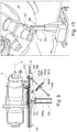
- Figure 7 shows schematically a cross section A ( cf. Fig. 1 ) through a second sliding mechanism 16 for pivoting the sledge 151 relative to the carriage 15.
- an engagement member 162 that is basically an L profile such that one leg extends vertically along the side wall 150 of the carriage 15 while the other leg extends substantially parallel to the concave top wall 153.
- a threaded recess 163 In the vertical leg of engagement member 162 is provided a threaded recess 163, the recess 163 being a through hole, into which a threaded bolt of a screw 161 engages. The bolt protrudes with a free end 162 towards the side wall 150 of the carriage 15.
- the bolt may be translated, in Fig. 5 , to the left with respect to the engagement member 162.
- the sledge 151 is bearing against a bearing element 165 that is provided on a concave top section 153 of the outer top wall of the carriage 15.
- the concave top wall 153 of the carriage has a part cylindrical shape, the cylinder axis being parallel to the longitudinal axis L of the carriage 15. Due to the fixed connection between the engagement member 162 and the sledge 151, the sledge 15 is shifted, on the bearings 165, to the right as the screw 161 is screwed into the threaded recess 163 pushing away the engagement member 162 from the vertical part of the carriage wall 150.
- the sliding motion of the sledge 151 on the carriage 15 is a pivot motion along the direction (e), i.e. a pivot motion about the longitudinal axis L of the carriage 15.
- FIG 8 shows schematically a cross section B ( cf. Fig. 1 ) through a third sliding mechanism 17 for sliding motion of the sledge151 arranged on the carriage 15.
- the third sliding mechanism 17 comprises a screw 171 that extends through the distal end of the distal stage module 124 of the beam 120.
- the module 124 is provided with a horizontal through opening 1241 into which a threaded sleeve 172 is inserted. This threaded sleeve 172 meshes with the screw 171.
- the screw 171 further extends through recesses 154 in the wall 150 of the carriage 15.
- the screw 171 has tapered end portions 173.
- the tapered end portions 173 may be provided on the outside with heads (not shown) that protrude over the recesses 154.
- the screw further comprises two plates 174 which radially extend over the sides of a wall 150 of the carriage 15 thereby fixing the relative position of the carriage 15 to the screw 171 with respect to the direction of the axial extension of the screw which is the direction of motion d. for easier rotation of the screw 171 a disk 175.
- the screw 171 translates in the sleeve 172 such that the carriage 15 may be shifted to the left or to the right. Accordingly, through activating the third sliding mechanism 17 a horizontal translation of the carriage 15 along the screw 171, i.e. along the motion (d) in Fig. 4 , may be carried out.
- Figure 9 shows the first pivoting mechanism 152.
- the carriage 15 is pivotably arranged on the beam module 124, wherein the pivot axis is horizontal and perpendicular to the longitudinal axis L of the carriage 15.
- the first pivoting mechanism 152 includes a bracket 1526 that extend from said pivot axis along the distal beam module 124 in order to provide leverage to an extension mechanism arranged between a free bottom end of the bracket 1526 and an end portion of the outer wall 150 of the carriage 15. Said free bottom end of the bracket 1526 and said end portion of the outer wall 150 are connected to one another by means of threaded rods 1520, 1525 and threaded cylinders 1521, 1524.
- Said threaded rods 1520 translate into or out of said threaded cylinders 1521, 1524 upon rotating a hand actuation 1522 or a chain actuator 1523. Thereby, a distance between said free bottom end of the bracket 1526 and an end portion of the outer wall 150 may be changed, whereupon the pivoting motion (c) about the first pivot axis occurs.
- Fig. 9 shows the first sliding mechanism 18.
- the first sliding mechanism 18 comprises a second spindle 181 which extends in the longitudinal direction L along the carriage 15.
- the second spindle 181 may be a self-breaking spindle.
- On said threaded spindle 181 is arranged a thrust block 183 which is fixedly attached to the sledge 151.
- the second spindle 181 is rotatable by hand or, additionally or in the alternative, by means of a motor 182 provided on the carriage 15. Upon rotation the second spindle 181 by hand or by the motor 182, the sledge 151 translated on said thrust block 183 along the spindle 181 and may be brought in extended to deliver or receive a turbine part from the mounting port 12.
- the motor 182 is preferably a pneumatic motor operated by remote control valves for allowing a smooth and precise fine positioning of the combustor 1, the combustor 1 being loaded onto the sledge 151.
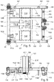
- the base frame 101 is now described in more detail with reference to Figures 5 and 6 .
- the base frame 101 is a frame construction comprising a plurality of beams 103-105 intersected with a plurality of transverse beams 106-110 connected to one another to have a sturdy frame.
- On the top side of the base frame 101 may be arranged plates 1020 such that users may step onto the base frame 101.
- On said plates 1020 may also be arranged the sledge 151 for storing the apparatus 100 or different types of sledges 151 for different combustor types or mounting ports 12.
- a compartment 102 ( cf. Figs. 4 , 10 ) for carrying batteries and at least one charger for the supply of the electrical motors 115, 116 or other equipment may be stored in said compartment 102.
- the compartment 102 has, however, also the effect of further stiffening the base frame 101.
- valves/compressor or a hydraulic aggregate may also be stored in the compartment 102.
- the twin wheels 111-114 On the bottom side of the frame 101 are arranged the twin wheels 111-114.
- the wheels 111-114 may be arranged in the triangular arrangement of wheels 111-114. This arrangement is depicted in Fig. 5 .
- the wheels 111-114 are hinged in wheel suspensions 1110-11140, respectively.
- the two left wheels in Fig. 5 are suspended in rigid wheel suspensions 1110, 1120, respectively.
- These rigid wheels 111, 112 are each driven by one electrical motor 115 that is attached to the base frame 101 in a motor suspension 1150.
- the wheels 113, 114 to the right in Fig. 5 are rotatable wheels that are hinged to the base frame 101 in rotatable wheel suspensions 1130, 1140, respectively.
- the motors 115, 116 have water and dustproof casings.
- the electric motor 116 is attached to the base frame 101 in a suspension 1160. Said electric motor 116 is configured for actuation the first spindle 126 in order to move the telescopic beam 120. Accordingly, the electric motor 116 comprises a driven axle 1161 which is coupled to a drive belt 1162. Instead of the belt 1162 also a gear may be employed.
- the spindle 126 is arranged in a cavity 1211 of the proximal stage module 121 and has at its proximal end a coupling 127 for coupling the spindle 126 to the drive axle 1161 by means of said drive belt 1162. Accordingly, the telescopic beam 120 may be actuated by means of said electric motor 116.
- the coupling 127 may also include a safety brake in case of failure of the motor 116 or of the motion transmission to the spindle 126.
- the base frame 101 comprises support members 117 that are arranged on the base frame 101 to extend from the base frame 101 toward the ground 90 for further improving the stability of the apparatus 100 during clashes that may occur.
- the mobile base frame 101 also comprises extendable support members 118 on slider beams 119.
- the slider beams 119 may be slid in or out of the longitudinal beams 103, 106 (to the right in Fig. 5 ) such that the slider beams 119 are moveable out of the frame 101 or back into the frame 101.
- the extendable support members 118 are arranged on free ends of the slider beams 119. Moreover, the extendable support members 118 are translatable to come into contact with the ground 90. Thereby, additional stability is gained.
- a shiftable length of the slider beams 119 may be 0.5 meter to 1.5 meters.
- the support members 118 may also be translated away from the ground 90 such that the base frame 101 may be rolled on the ground 90 without the support member 118 touching the ground 90. Accordingly, the slider beams 119 may also stay in the extended position during movements of the base frame 101. For storing purposes, however, the slider beams 119 may be shiftable substantially entirely into the respective frame beam 103, 106.
- Figures 10 to 12 show how the combustor 1 is delivered to the mounting port 12 of the annular combustor assembly 13 of the gas turbine 10.
- Figure 10 shows the apparatus 100 while delivering the combustor 1 to the mounting port 12 of the gas turbine 10.
- the apparatus 100 is placed under the mounting port 12; the beam 120 is extended to deliver said combustor 1, while the carriage 15 is properly inclined position and the sledge 151 is loaded with the combustor 1 and positioned in a retracted position. Then the sledge 151 is extended, the mechanisms 16, 17, 152 further used to adjust the combustor properly.
- the beam 120 is collapsed by actuation of the first spindle126 ( cf. Fig. 11 ). With a collapsed beam 120, the apparatus 100 is in park position and moved away from the service zone 11 ( cf. Fig. 12 ).
- Figure 13 shows how the combustor 1 may be loaded onto the carriage 15.
- the turbine part here the combustor 1
- the turbine part here the combustor 1
- the combustor 1 is attached to a crane 91 by means of chain blocks 93 and one single sling 92.
- the combustor 1 may be oriented properly with reference to the measurement devices 95, 96, whereupon apparatus 100 is placed on the ground 90 under the combustor 1 by means of the mobile base frame 101 and the carriage 15 is properly oriented by means of the telescopic beam 120 and the motion mechanisms 16, 17, 18, 152.
- the combustor 1 is received on the specifically for said combustor 1 designed sledge 151 and fastened thereon.
- Figure 14 shows the combustor 1 loaded onto the carriage 15 of the apparatus 100, ready for being delivered to the respective mounting port 12.
- any motor 115, 116, 182 described herein may be a standard electrical type, pneumatic, or hydraulic motor or the like.
- any motor may be controlled by the control panel 1210 and/or by a remote control device, the latter being advantageous if the user wants to step away from apparatus 100 during operation, e.g., for space or safety reasons.
- the apparatus 100 may also be controlled by embedded remote controls. The remote controls frequency can be changed depending on the country rules.
- the apparatus 100 may be designed such that the beam 120, including spindle 126 and carriage 15, may be disassembled such that the apparatus 100 may be compactly stored or shipped.
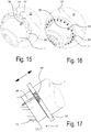
- Figure 15 shows a perspective view of the combustor 1 approaching the final position in port 12, the combustor 1 being engaged with by its flange 97 to and guided by guiding pins 96.
- the guiding pins 96 are attached on the annular combustor assembly 13 such that they protrude into diametrically spaced recesses 98 on a flange 97 of the combustor 1.
- Figure 17 shows a side view of the combustor 1 approaching the final position. As can be seen, the pins 96 offer guidance and orientation help.
- Figure 16 shows a perspective view of the combustor 1 in final position, with studs 99 being inserted into the recesses 98, while the guiding pins 96 are still inserted in the assembly 13 and protrude over said flange 97.
- the pins 96 may be removed and further studs 99 may be inserted to finally fasten the flange 97 and therefore the combustor 1 to the annular combustor assembly 13.
- One preferred embodiment of the method for moving a combustor 1 to a combustor assembly 13 of the gas turbine 10 may be as follows:
- the procedure for removing the combustor 1 is just the backwards procedure as outlined above.
- the present invention therefore provides a tool for efficient movement of a combustor and/or a sequential liner which may shorten down-times of the gas turbine 10.
Landscapes
- Engineering & Computer Science (AREA)
- Mechanical Engineering (AREA)
- General Engineering & Computer Science (AREA)
- Chemical & Material Sciences (AREA)
- Combustion & Propulsion (AREA)
- Automatic Assembly (AREA)
- Tents Or Canopies (AREA)
Claims (12)
- Appareil de remplacement de pièce de turbine (100) pour déplacer une chambre de combustion (1) et/ou un revêtement séquentiel d'une turbine à gaz industrielle (10) depuis et vers un orifice de montage (12) de la turbine à gaz (10), l'appareil (100) comprenant :un bâti mobile (101) avec un mécanisme de déplacement (111 - 114) pour le mouvement de translation sensiblement horizontal (b, g) sur le sol (90) ;un arbre verticalement extensible (120) fixé au et s'étendant à partir du bâti mobile (101) ; etun chariot (15) fixé audit bras extensible (120) de sorte que le chariot (15) peut être déplacé verticalement par rapport au bâti mobile (101) ;où l'appareil de remplacement de pièce de turbine (100) est adapté pour recevoir ladite chambre de combustion (1) et/ou le revêtement séquentiel dans ledit chariot (15) et pour déplacer verticalement ladite chambre de combustion (1) reçue et/ou le revêtement séquentiel au moyen dudit bras extensible (120) depuis et vers ledit orifice de montage (12) ;le chariot (15) comprenant un premier mécanisme de pivotement (152), le chariot (15) étant fixé au bras extensible (120) afin de pouvoir pivoter le long d'un premier mouvement de pivot (c) autour d'un premier axe de pivot au moyen dudit premier mécanisme de pivot (152), le premier axe de pivot s'étendant horizontalement et perpendiculairement à la direction longitudinale (L) du chariot (15) ;le chariot (15) comprenant une cale (151) pour la mise en place de la chambre de combustion (1) sur le chariot (15), la cale (151) étant agencée sur une première surface (150) du chariot (15) par le biais d'un dispositif coulissant (16 ; 18) de sorte que la cale (151) est mobile dans un mouvement coulissant (h ; e) par rapport audit chariot (15) le long d'une direction longitudinale (L) du chariot (15) et/ou perpendiculairement à la direction longitudinale (L) du chariot (15) ;l'appareil étant caractérisé en ce que la première surface (150) du chariot (15) est concave de sorte qu'un mouvement coulissant de la cale (151) sur la première surface perpendiculaire à la direction longitudinale (L) du chariot (15) est un second mouvement de pivot (e) autour d'un second axe de pivot parallèle à la direction longitudinale (L) du chariot (15), le dispositif coulissant (16, 18) comprenant un deuxième mécanisme coulissant (16) pour déplacer ledit chariot (15) sur la première surface (150) le long du second mouvement de pivot (e).
- Appareil de replacement de pièce de turbine (100) selon la revendication 1, dans lequel ledit bras extensible (120) est une poutre télescopique (120 - 124) mobile le long d'un mouvement vertical (a).
- Appareil de replacement de pièce de turbine (100) selon la revendication 1 ou 2, dans lequel ledit bras extensible (120) comprend au moins une première broche (126) pour actionner ledit bras extensible (120) afin de déplacer verticalement ledit chariot (15), ledit bras extensible (120) et ladite première broche (126) ayant de préférence une conception à trois étages, quatre étages ou cinq étages et/ou, de préférence, ledit bras extensible (120) étant adapté pour se déplacer sur une distance verticale d'au moins 1,5 mètre, de préférence d'au moins 3 mètres, 5 mètres ou 10 mètres.
- Appareil de replacement de pièce de turbine (100) selon la revendication 1, dans lequel ledit dispositif coulissant (16; 18) comprend un premier mécanisme coulissant (18) avec au moins une seconde broche (181) et un bloc de poussée (183), ledit bloc de poussée (183) pouvant effectuer un mouvement de translation le long de la seconde broche (181) et étant fixé à la cale (151) de sorte que la cale (151) est mobile le long d'un mouvement de translation (h) parallèle à ladite seconde broche (181) le long de la direction longitudinale (L) du chariot (150).
- Appareil de replacement de pièce de turbine (100) selon l'une quelconque des revendications 1 à 4, dans lequel le chariot (15) comprend un troisième mécanisme coulissant (17), le chariot (15) étant fixé au bras extensible (120) afin de pouvoir effectuer un mouvement de translation dans un mouvement de translation (d) le long d'un axe s'étendant horizontalement et perpendiculairement à la direction longitudinale (L) du chariot (15).
- Appareil de replacement de pièce de turbine (100) selon l'une quelconque des revendications 1 à 5, comprenant un dispositif de mesure (95) pour mesurer une position de rotation du chariot (15), le dispositif de mesure (95) étant adapté pour mesurer la position de rotation autour de deux axes de rotation horizontaux qui sont orientés de manière angulaire, de préférence perpendiculairement entre eux, le dispositif de mesure (95) comprenant de préférence un double niveau à bulle (95).
- Appareil de replacement de pièce de turbine (100) selon l'une quelconque des revendications 1 à 6, dans lequel le bâti de base (101) comprend des éléments roulants (111 - 114) pour rouler sur le sol (90).
- Appareil de replacement de pièce de turbine (100) selon la revendication 7, dans lequel lesdits éléments roulants (111 - 114) sont des roues, de préférence au moins trois, plus préférentiellement quatre roues (111 - 114) ou plus, et lesdites roues (111 - 114) étant agencées selon un agencement triangulaire ou rectangulaire, de préférence carré.
- Appareil de replacement de pièce de turbine (100) selon la revendication 8, dans lequel au moins une roue (111 - 114), de préférence deux roues voisines (111, 112 ; 113, 114) ou toutes les roues (111 - 114) peuvent tourner autour d'un axe de rotation vertical.
- Kit de pièces comprenant un appareil de remplacement de pièce de turbine (100) selon l'une quelconque des revendications 1 à 9 et une pluralité de chariots (150) ou parties de chariot, en particulier des cales (151), de sorte que, en fonction d'un emplacement d'un orifice de montage (12) sur la turbine à gaz (10) et/ou la pièce de turbine (1) à déplacer, un appareil de remplacement de pièce de turbine (100) avec une configuration appropriée du chariot (15) choisi parmi le kit de pièces peut être assemblé.
- Procédé pour déplacer une chambre de combustion (1) et/ou un revêtement séquentiel d'une turbine à gaz industrielle (10) depuis et vers un orifice de montage (12) de la turbine à gaz (10), comprenant les étapes consistant à :(a) déterminer une position de fixation absolue de la chambre de combustion (1) et/ou du revêtement séquentiel sur ladite turbine à gaz (10) ;(b) utiliser l'appareil de remplacement de pièce de turbine (100) selon l'une quelconque des revendications 1 à 9 pour déplacer ladite chambre de combustion (1) et/ou le revêtement séquentiel.
- Procédé selon la revendication 11 dépendant de la revendication 6, dans lequel la position de fixation absolue de la chambre de combustion (1) et/ou du revêtement est déterminée au moyen du dispositif de mesure (95), le dispositif de mesure (95) étant adapté pour mesurer la position de rotation autour de deux axes de rotation horizontaux qui sont orientés de manière angulaire, de préférence perpendiculairement entre eux, le dispositif de mesure (95) étant de préférence un double niveau à bulle (95), où au moins une, de préférence deux broches de guidage (96) sont agencées sur la chambre de combustion (1) et/ou le revêtement ou sur le carter (13) de la turbine à gaz (10) pour la réception dans des fentes correspondantes dans le carter (13) de la turbine à gaz (10) ou dans la chambre de combustion (1) et/ou le revêtement, les deux broches de guidage (96) étant de préférence un autre dispositif de guidage et/ou de mesure (96) pour mesurer la position de rotation par rapport à un axe vertical (V).
Priority Applications (5)
| Application Number | Priority Date | Filing Date | Title |
|---|---|---|---|
| EP15158898.5A EP3067310B1 (fr) | 2015-03-12 | 2015-03-12 | Appareil de remplacement d'une chambre de combustion de turbine à gaz et procédé |
| US15/066,968 US10071450B2 (en) | 2015-03-12 | 2016-03-10 | Turbine part replacing apparatus |
| JP2016048972A JP2016188639A (ja) | 2015-03-12 | 2016-03-11 | タービン部品交換装置 |
| CN201610142564.8A CN105971677B (zh) | 2015-03-12 | 2016-03-14 | 涡轮部件更换装置 |
| KR1020160030284A KR20160110265A (ko) | 2015-03-12 | 2016-03-14 | 터빈 부품 교체 장치 |
Applications Claiming Priority (1)
| Application Number | Priority Date | Filing Date | Title |
|---|---|---|---|
| EP15158898.5A EP3067310B1 (fr) | 2015-03-12 | 2015-03-12 | Appareil de remplacement d'une chambre de combustion de turbine à gaz et procédé |
Publications (2)
| Publication Number | Publication Date |
|---|---|
| EP3067310A1 EP3067310A1 (fr) | 2016-09-14 |
| EP3067310B1 true EP3067310B1 (fr) | 2019-05-08 |
Family
ID=52633183
Family Applications (1)
| Application Number | Title | Priority Date | Filing Date |
|---|---|---|---|
| EP15158898.5A Active EP3067310B1 (fr) | 2015-03-12 | 2015-03-12 | Appareil de remplacement d'une chambre de combustion de turbine à gaz et procédé |
Country Status (5)
| Country | Link |
|---|---|
| US (1) | US10071450B2 (fr) |
| EP (1) | EP3067310B1 (fr) |
| JP (1) | JP2016188639A (fr) |
| KR (1) | KR20160110265A (fr) |
| CN (1) | CN105971677B (fr) |
Families Citing this family (20)
| Publication number | Priority date | Publication date | Assignee | Title |
|---|---|---|---|---|
| US9803739B2 (en) * | 2015-04-16 | 2017-10-31 | General Electric Company | Gearbox adjustment system |
| US10088167B2 (en) * | 2015-06-15 | 2018-10-02 | General Electric Company | Combustion flow sleeve lifting tool |
| US10082042B2 (en) * | 2015-06-22 | 2018-09-25 | United Technologies Corporation | Case coupling and assembly |
| US10662816B2 (en) * | 2016-04-12 | 2020-05-26 | General Electric Company | System and method to move turbomachinery |
| EP3458687B1 (fr) | 2016-05-20 | 2021-01-13 | General Electric Company | Élément de support modulaire et procédé d'installation d'un ensemble turbine utilisant celui-ci |
| CN107525498A (zh) * | 2017-09-06 | 2017-12-29 | 河南送变电建设有限公司 | 一种用于测量设备的二维定位机构 |
| CN109304598A (zh) * | 2018-11-18 | 2019-02-05 | 大连四达高技术发展有限公司 | 发动机多自由度装配机构 |
| DE102019201797A1 (de) * | 2019-02-12 | 2020-08-13 | MTU Aero Engines AG | Wendestand |
| KR102207789B1 (ko) * | 2019-03-28 | 2021-01-26 | 두산중공업 주식회사 | 지그장치 |
| KR102183508B1 (ko) * | 2019-03-28 | 2020-11-26 | 두산중공업 주식회사 | 지그장치 |
| KR102183507B1 (ko) * | 2019-04-08 | 2020-11-26 | 두산중공업 주식회사 | 지그장치 |
| JP7236401B2 (ja) * | 2020-01-29 | 2023-03-09 | 株式会社中部プラントサービス | ガスタービン燃焼器取出し移送用吊治具および取出し移送方法。 |
| KR102309311B1 (ko) * | 2020-03-09 | 2021-10-07 | 두산중공업 주식회사 | 연소기 설치 방법 |
| KR102268660B1 (ko) * | 2020-03-09 | 2021-06-23 | 두산중공업 주식회사 | 연소기 설치 장치 |
| KR102309312B1 (ko) * | 2020-03-09 | 2021-10-07 | 두산중공업 주식회사 | 연소기 설치 장치 |
| KR102268661B1 (ko) * | 2020-03-09 | 2021-06-23 | 두산중공업 주식회사 | 연소기 설치 방법 |
| CN112025666B (zh) * | 2020-09-21 | 2025-01-17 | 成都市珑熙科技有限公司 | 一种航空涡轮发动机设备装配用车 |
| US11560298B2 (en) * | 2021-01-05 | 2023-01-24 | The Boeing Company | Engine installation systems and related methods |
| CN114227208B (zh) * | 2022-01-11 | 2024-09-27 | 山东钢铁股份有限公司 | 一种悬挂式链轮更换装置 |
| US12281590B2 (en) | 2022-06-29 | 2025-04-22 | Ge Infrastructure Technology Llc | System and method for installation or removal of one or more combustion cans |
Family Cites Families (9)
| Publication number | Priority date | Publication date | Assignee | Title |
|---|---|---|---|---|
| JP2877296B2 (ja) | 1995-09-11 | 1999-03-31 | 三菱重工業株式会社 | ガスタービン燃焼器の取付、取外し装置 |
| ES2177812T3 (es) * | 1995-10-19 | 2002-12-16 | Mitsubishi Heavy Ind Ltd | Dispositivo de reempllazo de quemadores. |
| US5816367A (en) * | 1995-11-30 | 1998-10-06 | Stanley Aviation Corporation | Jet aircraft engine transport apparatus |
| US6485247B1 (en) * | 2000-09-28 | 2002-11-26 | The Boeing Company | Engine uplift loader |
| US6702064B2 (en) * | 2002-04-02 | 2004-03-09 | Chin Piao Huang | Lifter having tiltable support rack assembly |
| CN201843650U (zh) * | 2010-11-16 | 2011-05-25 | 山东齐鲁电机制造有限公司 | 移动支撑装置 |
| EP2551473A1 (fr) * | 2011-07-27 | 2013-01-30 | Alstom Technology Ltd | Dispositif de fixation opposée de deux composants d'une boîte d'une turbine à gaz |
| US9486899B2 (en) * | 2013-11-25 | 2016-11-08 | General Electric Company | Method for positioning of equipment |
| WO2015168637A1 (fr) * | 2014-05-02 | 2015-11-05 | Morey Joel T | Support pour moteur d'avion |
-
2015
- 2015-03-12 EP EP15158898.5A patent/EP3067310B1/fr active Active
-
2016
- 2016-03-10 US US15/066,968 patent/US10071450B2/en active Active
- 2016-03-11 JP JP2016048972A patent/JP2016188639A/ja active Pending
- 2016-03-14 KR KR1020160030284A patent/KR20160110265A/ko not_active Withdrawn
- 2016-03-14 CN CN201610142564.8A patent/CN105971677B/zh active Active
Non-Patent Citations (1)
| Title |
|---|
| None * |
Also Published As
| Publication number | Publication date |
|---|---|
| EP3067310A1 (fr) | 2016-09-14 |
| KR20160110265A (ko) | 2016-09-21 |
| US10071450B2 (en) | 2018-09-11 |
| CN105971677A (zh) | 2016-09-28 |
| JP2016188639A (ja) | 2016-11-04 |
| CN105971677B (zh) | 2020-03-17 |
| US20160263715A1 (en) | 2016-09-15 |
Similar Documents
| Publication | Publication Date | Title |
|---|---|---|
| US10071450B2 (en) | Turbine part replacing apparatus | |
| US11572806B2 (en) | Turbine bearing maintenance apparatus and method | |
| EP0800892B1 (fr) | Appareil a remplacer les bruleurs | |
| EP1215119B1 (fr) | Dispositif d'alignement et d'installation à six axes | |
| EP2873621B1 (fr) | Support de moteur à turbine à gaz | |
| EP2613023B1 (fr) | Système d'alignement d'une turbomachine | |
| KR101144001B1 (ko) | 액체로켓엔진에서의 터보펌프 조립 장치 | |
| CN113400264A (zh) | 一种用于阀门设备检修的检修台架 | |
| EP2949885B1 (fr) | Procédé et dispositif pour le montage et le démontage d'un composant de turbine | |
| EP1785350B1 (fr) | Dispositif pour manipuler des charges lourdes | |
| EP2138402A2 (fr) | Système d'arrimage modulaire variable | |
| RU2607721C1 (ru) | Манипуляционное контрольное устройство | |
| CN113666263A (zh) | 风电预制砼塔筒吊装平台的变径模块 | |
| CN200997341Y (zh) | 大型电力隔离开关操作机构的安装辅助装置 | |
| CN114249248A (zh) | 一种航空配件生产用组装系统 | |
| CN101000830A (zh) | 大型电力隔离开关操作机构的安装辅助装置 | |
| CN112660978B (zh) | 一种大尺寸异型舱段调姿工装及调姿方法 | |
| CN113146227A (zh) | 一种风管的螺栓拆装装置 | |
| CN103395342B (zh) | 一种台车轮拆装小车 | |
| CN218489930U (zh) | 波音737ng飞机发动机进气道拆装及存放的工具设备 | |
| CN121670575A (zh) | 一种用于船用螺旋桨快速拆卸的可调节工装及其使用方法 | |
| CN221454916U (zh) | 一种大型养路机械地沟型传动轴拆装装置 | |
| CA2206983C (fr) | Appareil a remplacer les bruleurs | |
| CN121726124A (zh) | 压力容器下封头的维护装置、拆卸方法以及安装方法 | |
| JP4399233B2 (ja) | 巨大および重量部品の取外しおよび交換装置 |
Legal Events
| Date | Code | Title | Description |
|---|---|---|---|
| PUAI | Public reference made under article 153(3) epc to a published international application that has entered the european phase |
Free format text: ORIGINAL CODE: 0009012 |
|
| AK | Designated contracting states |
Kind code of ref document: A1 Designated state(s): AL AT BE BG CH CY CZ DE DK EE ES FI FR GB GR HR HU IE IS IT LI LT LU LV MC MK MT NL NO PL PT RO RS SE SI SK SM TR |
|
| AX | Request for extension of the european patent |
Extension state: BA ME |
|
| STAA | Information on the status of an ep patent application or granted ep patent |
Free format text: STATUS: REQUEST FOR EXAMINATION WAS MADE |
|
| 17P | Request for examination filed |
Effective date: 20170313 |
|
| RBV | Designated contracting states (corrected) |
Designated state(s): AL AT BE BG CH CY CZ DE DK EE ES FI FR GB GR HR HU IE IS IT LI LT LU LV MC MK MT NL NO PL PT RO RS SE SI SK SM TR |
|
| RAP1 | Party data changed (applicant data changed or rights of an application transferred) |
Owner name: ANSALDO ENERGIA SWITZERLAND AG |
|
| GRAP | Despatch of communication of intention to grant a patent |
Free format text: ORIGINAL CODE: EPIDOSNIGR1 |
|
| STAA | Information on the status of an ep patent application or granted ep patent |
Free format text: STATUS: GRANT OF PATENT IS INTENDED |
|
| INTG | Intention to grant announced |
Effective date: 20181019 |
|
| GRAS | Grant fee paid |
Free format text: ORIGINAL CODE: EPIDOSNIGR3 |
|
| GRAA | (expected) grant |
Free format text: ORIGINAL CODE: 0009210 |
|
| STAA | Information on the status of an ep patent application or granted ep patent |
Free format text: STATUS: THE PATENT HAS BEEN GRANTED |
|
| AK | Designated contracting states |
Kind code of ref document: B1 Designated state(s): AL AT BE BG CH CY CZ DE DK EE ES FI FR GB GR HR HU IE IS IT LI LT LU LV MC MK MT NL NO PL PT RO RS SE SI SK SM TR |
|
| REG | Reference to a national code |
Ref country code: GB Ref legal event code: FG4D |
|
| REG | Reference to a national code |
Ref country code: CH Ref legal event code: EP Ref country code: AT Ref legal event code: REF Ref document number: 1129829 Country of ref document: AT Kind code of ref document: T Effective date: 20190515 |
|
| REG | Reference to a national code |
Ref country code: DE Ref legal event code: R096 Ref document number: 602015029630 Country of ref document: DE Ref country code: IE Ref legal event code: FG4D |
|
| REG | Reference to a national code |
Ref country code: NL Ref legal event code: MP Effective date: 20190508 |
|
| REG | Reference to a national code |
Ref country code: LT Ref legal event code: MG4D |
|
| PG25 | Lapsed in a contracting state [announced via postgrant information from national office to epo] |
Ref country code: FI Free format text: LAPSE BECAUSE OF FAILURE TO SUBMIT A TRANSLATION OF THE DESCRIPTION OR TO PAY THE FEE WITHIN THE PRESCRIBED TIME-LIMIT Effective date: 20190508 Ref country code: NO Free format text: LAPSE BECAUSE OF FAILURE TO SUBMIT A TRANSLATION OF THE DESCRIPTION OR TO PAY THE FEE WITHIN THE PRESCRIBED TIME-LIMIT Effective date: 20190808 Ref country code: NL Free format text: LAPSE BECAUSE OF FAILURE TO SUBMIT A TRANSLATION OF THE DESCRIPTION OR TO PAY THE FEE WITHIN THE PRESCRIBED TIME-LIMIT Effective date: 20190508 Ref country code: PT Free format text: LAPSE BECAUSE OF FAILURE TO SUBMIT A TRANSLATION OF THE DESCRIPTION OR TO PAY THE FEE WITHIN THE PRESCRIBED TIME-LIMIT Effective date: 20190908 Ref country code: AL Free format text: LAPSE BECAUSE OF FAILURE TO SUBMIT A TRANSLATION OF THE DESCRIPTION OR TO PAY THE FEE WITHIN THE PRESCRIBED TIME-LIMIT Effective date: 20190508 Ref country code: SE Free format text: LAPSE BECAUSE OF FAILURE TO SUBMIT A TRANSLATION OF THE DESCRIPTION OR TO PAY THE FEE WITHIN THE PRESCRIBED TIME-LIMIT Effective date: 20190508 Ref country code: LT Free format text: LAPSE BECAUSE OF FAILURE TO SUBMIT A TRANSLATION OF THE DESCRIPTION OR TO PAY THE FEE WITHIN THE PRESCRIBED TIME-LIMIT Effective date: 20190508 Ref country code: HR Free format text: LAPSE BECAUSE OF FAILURE TO SUBMIT A TRANSLATION OF THE DESCRIPTION OR TO PAY THE FEE WITHIN THE PRESCRIBED TIME-LIMIT Effective date: 20190508 Ref country code: ES Free format text: LAPSE BECAUSE OF FAILURE TO SUBMIT A TRANSLATION OF THE DESCRIPTION OR TO PAY THE FEE WITHIN THE PRESCRIBED TIME-LIMIT Effective date: 20190508 |
|
| PG25 | Lapsed in a contracting state [announced via postgrant information from national office to epo] |
Ref country code: GR Free format text: LAPSE BECAUSE OF FAILURE TO SUBMIT A TRANSLATION OF THE DESCRIPTION OR TO PAY THE FEE WITHIN THE PRESCRIBED TIME-LIMIT Effective date: 20190809 Ref country code: RS Free format text: LAPSE BECAUSE OF FAILURE TO SUBMIT A TRANSLATION OF THE DESCRIPTION OR TO PAY THE FEE WITHIN THE PRESCRIBED TIME-LIMIT Effective date: 20190508 Ref country code: BG Free format text: LAPSE BECAUSE OF FAILURE TO SUBMIT A TRANSLATION OF THE DESCRIPTION OR TO PAY THE FEE WITHIN THE PRESCRIBED TIME-LIMIT Effective date: 20190808 Ref country code: LV Free format text: LAPSE BECAUSE OF FAILURE TO SUBMIT A TRANSLATION OF THE DESCRIPTION OR TO PAY THE FEE WITHIN THE PRESCRIBED TIME-LIMIT Effective date: 20190508 |
|
| REG | Reference to a national code |
Ref country code: AT Ref legal event code: MK05 Ref document number: 1129829 Country of ref document: AT Kind code of ref document: T Effective date: 20190508 |
|
| PG25 | Lapsed in a contracting state [announced via postgrant information from national office to epo] |
Ref country code: CZ Free format text: LAPSE BECAUSE OF FAILURE TO SUBMIT A TRANSLATION OF THE DESCRIPTION OR TO PAY THE FEE WITHIN THE PRESCRIBED TIME-LIMIT Effective date: 20190508 Ref country code: SK Free format text: LAPSE BECAUSE OF FAILURE TO SUBMIT A TRANSLATION OF THE DESCRIPTION OR TO PAY THE FEE WITHIN THE PRESCRIBED TIME-LIMIT Effective date: 20190508 Ref country code: RO Free format text: LAPSE BECAUSE OF FAILURE TO SUBMIT A TRANSLATION OF THE DESCRIPTION OR TO PAY THE FEE WITHIN THE PRESCRIBED TIME-LIMIT Effective date: 20190508 Ref country code: EE Free format text: LAPSE BECAUSE OF FAILURE TO SUBMIT A TRANSLATION OF THE DESCRIPTION OR TO PAY THE FEE WITHIN THE PRESCRIBED TIME-LIMIT Effective date: 20190508 Ref country code: AT Free format text: LAPSE BECAUSE OF FAILURE TO SUBMIT A TRANSLATION OF THE DESCRIPTION OR TO PAY THE FEE WITHIN THE PRESCRIBED TIME-LIMIT Effective date: 20190508 Ref country code: DK Free format text: LAPSE BECAUSE OF FAILURE TO SUBMIT A TRANSLATION OF THE DESCRIPTION OR TO PAY THE FEE WITHIN THE PRESCRIBED TIME-LIMIT Effective date: 20190508 |
|
| REG | Reference to a national code |
Ref country code: DE Ref legal event code: R097 Ref document number: 602015029630 Country of ref document: DE |
|
| PG25 | Lapsed in a contracting state [announced via postgrant information from national office to epo] |
Ref country code: IT Free format text: LAPSE BECAUSE OF FAILURE TO SUBMIT A TRANSLATION OF THE DESCRIPTION OR TO PAY THE FEE WITHIN THE PRESCRIBED TIME-LIMIT Effective date: 20190508 Ref country code: SM Free format text: LAPSE BECAUSE OF FAILURE TO SUBMIT A TRANSLATION OF THE DESCRIPTION OR TO PAY THE FEE WITHIN THE PRESCRIBED TIME-LIMIT Effective date: 20190508 |
|
| PLBE | No opposition filed within time limit |
Free format text: ORIGINAL CODE: 0009261 |
|
| STAA | Information on the status of an ep patent application or granted ep patent |
Free format text: STATUS: NO OPPOSITION FILED WITHIN TIME LIMIT |
|
| PG25 | Lapsed in a contracting state [announced via postgrant information from national office to epo] |
Ref country code: TR Free format text: LAPSE BECAUSE OF FAILURE TO SUBMIT A TRANSLATION OF THE DESCRIPTION OR TO PAY THE FEE WITHIN THE PRESCRIBED TIME-LIMIT Effective date: 20190508 |
|
| 26N | No opposition filed |
Effective date: 20200211 |
|
| PG25 | Lapsed in a contracting state [announced via postgrant information from national office to epo] |
Ref country code: PL Free format text: LAPSE BECAUSE OF FAILURE TO SUBMIT A TRANSLATION OF THE DESCRIPTION OR TO PAY THE FEE WITHIN THE PRESCRIBED TIME-LIMIT Effective date: 20190508 |
|
| PG25 | Lapsed in a contracting state [announced via postgrant information from national office to epo] |
Ref country code: SI Free format text: LAPSE BECAUSE OF FAILURE TO SUBMIT A TRANSLATION OF THE DESCRIPTION OR TO PAY THE FEE WITHIN THE PRESCRIBED TIME-LIMIT Effective date: 20190508 |
|
| PG25 | Lapsed in a contracting state [announced via postgrant information from national office to epo] |
Ref country code: MC Free format text: LAPSE BECAUSE OF FAILURE TO SUBMIT A TRANSLATION OF THE DESCRIPTION OR TO PAY THE FEE WITHIN THE PRESCRIBED TIME-LIMIT Effective date: 20190508 |
|
| REG | Reference to a national code |
Ref country code: CH Ref legal event code: PL |
|
| REG | Reference to a national code |
Ref country code: BE Ref legal event code: MM Effective date: 20200331 |
|
| PG25 | Lapsed in a contracting state [announced via postgrant information from national office to epo] |
Ref country code: LU Free format text: LAPSE BECAUSE OF NON-PAYMENT OF DUE FEES Effective date: 20200312 |
|
| PG25 | Lapsed in a contracting state [announced via postgrant information from national office to epo] |
Ref country code: LI Free format text: LAPSE BECAUSE OF NON-PAYMENT OF DUE FEES Effective date: 20200331 Ref country code: CH Free format text: LAPSE BECAUSE OF NON-PAYMENT OF DUE FEES Effective date: 20200331 Ref country code: FR Free format text: LAPSE BECAUSE OF NON-PAYMENT OF DUE FEES Effective date: 20200331 Ref country code: IE Free format text: LAPSE BECAUSE OF NON-PAYMENT OF DUE FEES Effective date: 20200312 |
|
| PG25 | Lapsed in a contracting state [announced via postgrant information from national office to epo] |
Ref country code: BE Free format text: LAPSE BECAUSE OF NON-PAYMENT OF DUE FEES Effective date: 20200331 |
|
| GBPC | Gb: european patent ceased through non-payment of renewal fee |
Effective date: 20200312 |
|
| PG25 | Lapsed in a contracting state [announced via postgrant information from national office to epo] |
Ref country code: GB Free format text: LAPSE BECAUSE OF NON-PAYMENT OF DUE FEES Effective date: 20200312 |
|
| PG25 | Lapsed in a contracting state [announced via postgrant information from national office to epo] |
Ref country code: MT Free format text: LAPSE BECAUSE OF FAILURE TO SUBMIT A TRANSLATION OF THE DESCRIPTION OR TO PAY THE FEE WITHIN THE PRESCRIBED TIME-LIMIT Effective date: 20190508 Ref country code: CY Free format text: LAPSE BECAUSE OF FAILURE TO SUBMIT A TRANSLATION OF THE DESCRIPTION OR TO PAY THE FEE WITHIN THE PRESCRIBED TIME-LIMIT Effective date: 20190508 |
|
| PG25 | Lapsed in a contracting state [announced via postgrant information from national office to epo] |
Ref country code: MK Free format text: LAPSE BECAUSE OF FAILURE TO SUBMIT A TRANSLATION OF THE DESCRIPTION OR TO PAY THE FEE WITHIN THE PRESCRIBED TIME-LIMIT Effective date: 20190508 Ref country code: IS Free format text: LAPSE BECAUSE OF FAILURE TO SUBMIT A TRANSLATION OF THE DESCRIPTION OR TO PAY THE FEE WITHIN THE PRESCRIBED TIME-LIMIT Effective date: 20190908 |
|
| P01 | Opt-out of the competence of the unified patent court (upc) registered |
Effective date: 20240430 |
|
| PGFP | Annual fee paid to national office [announced via postgrant information from national office to epo] |
Ref country code: DE Payment date: 20260320 Year of fee payment: 12 |