EP3067464B1 - Schienenbahn auf längsträgern, herstellungsverfahren - Google Patents
Schienenbahn auf längsträgern, herstellungsverfahren Download PDFInfo
- Publication number
- EP3067464B1 EP3067464B1 EP16305252.5A EP16305252A EP3067464B1 EP 3067464 B1 EP3067464 B1 EP 3067464B1 EP 16305252 A EP16305252 A EP 16305252A EP 3067464 B1 EP3067464 B1 EP 3067464B1
- Authority
- EP
- European Patent Office
- Prior art keywords
- aggregates
- sleepers
- rails
- bituminized
- layer
- Prior art date
- Legal status (The legal status is an assumption and is not a legal conclusion. Google has not performed a legal analysis and makes no representation as to the accuracy of the status listed.)
- Active
Links
Images

Classifications
-
- E—FIXED CONSTRUCTIONS
- E01—CONSTRUCTION OF ROADS, RAILWAYS, OR BRIDGES
- E01B—PERMANENT WAY; PERMANENT-WAY TOOLS; MACHINES FOR MAKING RAILWAYS OF ALL KINDS
- E01B1/00—Ballastway; Other means for supporting the sleepers or the track; Drainage of the ballastway
- E01B1/002—Ballastless track, e.g. concrete slab trackway, or with asphalt layers
- E01B1/004—Ballastless track, e.g. concrete slab trackway, or with asphalt layers with prefabricated elements embedded in fresh concrete or asphalt
-
- E—FIXED CONSTRUCTIONS
- E01—CONSTRUCTION OF ROADS, RAILWAYS, OR BRIDGES
- E01B—PERMANENT WAY; PERMANENT-WAY TOOLS; MACHINES FOR MAKING RAILWAYS OF ALL KINDS
- E01B3/00—Transverse or longitudinal sleepers; Other means resting directly on the ballastway for supporting rails
- E01B3/28—Transverse or longitudinal sleepers; Other means resting directly on the ballastway for supporting rails made from concrete or from natural or artificial stone
- E01B3/38—Longitudinal sleepers; Longitudinal sleepers integral or combined with tie-rods; Combined longitudinal and transverse sleepers; Layers of concrete supporting both rails
Definitions
- the present invention relates to a railway on longitudinal rails and a method for producing it. It has applications in the field of civil engineering and the construction or rehabilitation of railways for rail traffic or even trams or subways.
- a railway track comprising a pair of running rails parallel to each other and fixed on supports formed of elongate longitudinal sills and resting on a seat extended under the track and arranged on a platform.
- Railways can be classified into two broad categories: ballasted and non-ballasted.
- the alternative to the ballasted track is the slab track for which the ballast is replaced by base layers consisting of concrete slabs or asphalt.
- Slab railways are interesting because of their greater structural stability and longer life cycle.
- Concrete slab railways suffer from certain drawbacks: higher construction costs, particularly when the site has a low lift capacity, a high railroad thickness close to the ballast, high sensitivity to construction defects (water drainage and earthworks must be perfect, with the risk of deteriorating the concrete more quickly), longer construction time with very high curing time for cast-in-place slabs, more demanding sizing depending on capacity It is more noisy compared to ballast tracks and, finally, it leads to very high CO 2 emissions due to the use of concrete.
- bituminous mixes in the superstructure or in the sub-ballast layer meets the modern requirements of railways.
- the composition of the mix By varying the composition of the mix, the ratio of the various constituents as well as the size distribution of the granular particles, the properties of the final mixture can be adapted according to the specific needs of the construction.
- the production of bituminous mixes takes place in mobile or static plants which are now well controlled.
- railways are known equipment that may for some have been made for many years with, at the time, constraints that have nothing to do with those of our present day. This is particularly the case for subways / tunnels or railway passages under bridge type structures.
- the solution proposed here focuses on reducing the height / thickness of the railway itself and taking into account the particular environment of the underground (temperature, hydrometry, ).
- the proposed solution also allows better durability and supported loads, which reduces maintenance.
- the invention can however be applied to other areas, tracks under bridges or even free paths.
- the invention relates to a railway comprising a pair of running rails parallel to each other in a longitudinal direction and fixed on supports, the supports resting on a seat extended under the track and arranged on a platform.
- the supports provide continuous support for the rails and are formed of elongate longitudinal sills, placed end to end and arranged under each of the rails, the seat comprises at least one layer of bituminous aggregates, and each of the rails rests by its skid on the sills with the interposition of a damping midsole, the rails being fixed to the sills, the sills being glued by a polymerizable synthetic resin on said at least one layer of bituminous aggregates of the seat .
- the invention also relates to a method for producing a railroad track, the railroad extending along the length and comprising a pair of running rails parallel to each other and resting on supports, the supports resting on a seat extended under the track and arranged on a platform.
- said method after at least installation of the stringers and their bonding, it spreads further surface of the top layer of bituminous aggregates armed a surface layer of bituminous aggregates, said surface layer of bituminous aggregates is preferably armed.
- anchors are further anchored to the seat by anchoring means, said anchoring means being caused to pass through the longitudinal members and at least a portion of the seat.
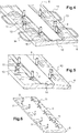
- the track 1 of the invention is ballastless and has a multilayer structure with a layer stiffness which decreases from top to bottom, the bottom layer further providing protection against freezing.
- the rails 7 of the track have a continuous support on longitudinal longitudinal rails 6 of cement-based concrete, the stringers may include an overflowing reinforcement 14. This continuous support makes it possible to improve the transmission of the forces by decreasing the load peaks through the different layers. This continuous support also reduces fatigue in the rail and thus increases the life of the rail.
- These different layers are laid on a platform 2 of minimum resistance at 120 MPa.
- the reinforcement with a conventional armament or "METALFLEX®” can be omitted.
- Cladding layers consisting of either a modified bitumen-elastomer emulsion or a pure bitumen emulsion may furthermore be used on the platform and / or between the layers of the seat to improve hanging.
- the lower 3 and upper 4 layers form a seat for the layer consisting of longitudinal stringers 6.
- Bituminous aggregates are typically bituminized hot mixes.
- the lower layer 3 of bituminous aggregates is unarmed and comprises materials having a larger particle size than that of the upper layer 4 which is itself reinforced. It is also possible to use a / plant binders in bituminous aggregates.
- METALFLEX® is a generally modified bituminous mix composite and a three-dimensional honeycomb structural steel reinforcement.
- the METALFLEX® process makes it possible to obtain a material composed of reinforced and confined mixes with exceptionally high resistance to rutting and cracking. If necessary, the details of this process can be found in the French patent applications FR88 / 16265 and FR99 / 12968 .
- the three-dimensional frame has honeycomb honeycomb structure. It is made from strips or sheets of steel. Fixing the reinforcement on the lower layer can be considered and it is then carried out with special jumpers, steel, nailed ("spitted") in the support.
- bituminous aggregates of the layers have a relatively high stiffness and good resistance to tensile forces and vertical deformation.
- the impermeability of bituminous aggregate layers prevents the infiltration of rain or runoff and the deleterious effects of extreme thermal changes (freezing and thawing). This impermeability also prevents vertical hydraulic transport of sludge and fine particles. Because of the high mechanical moduli of the bituminous aggregate layers, a reduction in tensile and shear stresses is achieved inside the track. The track then undergoes less fatigue, less wear and therefore requires less maintenance. Cracks are less likely to appear. The necessary corrections in the position of the track, especially following the settlement of an embankment, can be quickly and easily performed.
- bituminous aggregates lead to a reduction of vibrations and noise as the trains pass.
- the use of polymer modified bitumen, and / or rubber or the like, for bituminous aggregates can further enhance the effect. amortization.
- the load can be put on the asphalt almost immediately after cooling, the construction time of the track is thus shorter than in other methods of construction, especially those on slab.
- the platform 2 may be a prepared floor or a raft, the latter case in particular in a tunnel implementation.
- an anti-vibratile mat is installed between the platform and the seat.
- a surface layer 5 of bituminous aggregates is additionally added to the surface of the reinforced / reinforced top layer 4, on either side of the two rails 7 and the stringers 6 of the track 1.
- This surface layer 5 can also be reinforced / reinforced and in this case in the same way as that of the upper layer 4.
- the surface layer 5 may be, alternatively, another composite material. The upper face of the surface layer 5 is brought to the level of the upper face of the sill.
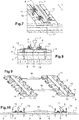
- This surface layer 5 reinforces the lateral support of the longitudinal members 6 in addition to the fixing by the resin 12 and the inking of the longitudinal members 6 in the seat 3, 4 by anchoring means 13 passing through the longitudinal members and the seat. Because of their positions along the longitudinal members, the anchoring means also pass through the bonding resin layer 12 as visible on the Figures 7 and 8 .
- the stringers are therefore anchored in the bituminous aggregate base and for this purpose, the use of tapered screws for anchoring makes it possible to avoid the shearing work of the polymerized bonding resin 12.
- the surface layer also allows drainage which is provided by the achievement of slopes on the profile of the channel leading the water in gutters or channels 9. The drained water is removed by means of manholes placed regularly in the axis of the track.
- This superficial layer 5 which provides the surface finish of the track is particularly useful in urban or quay zone and / or to allow the rolling of motor vehicles with pneumatic wheels.
- the bituminous aggregates of the base 3, 4 and of the optional surface layer 5 may be laterally confined by confinement means in order to prevent any creep of the materials.
- the confinement means may correspond for at least a portion of them to the piers of the tunnels.
- the stringers are straight elongated elements and the two longitudinal ends of each sill can be flat, perpendicular to the main direction of the sill, or have a contoured shape.
- the flat shape of the ends of sill is preferably used for the parts of lanes in alignment (straight) because, in the curves, because of the angular offset between two successive lanyards, a corner opening is created at the junction between the two successive stringers.
- the stringers 6 comprise a universal table for receiving and fixing the rail.
- This universal table may for example be of a type that allows the use of three types of compatible fasteners and any type of flat shoe rails.
- a rail of lower height is used than the rails conventionally used because of the advantage of the continuous support which does not impose a large vertical inertia module.
- the stringers 6 are prefabricated concrete modules with high performance type DUCTAL® or composite material cast or extruded or a conventional concrete with metal reinforcements. They are armed or unarmed, fibered or non-fiberized.
- the sills have shapes and sizes that can be adapted to the needs: in particular in length in order to take into account the curves and the alignments on the two rows of rails, to allow a continuous support of the rail, to integrate a universal table, to ensure the geometric adjustment of the lane before fixing by gluing, allow the pouring of the fixing resin through tapping holes 11 and vents through the sill, to ensure the integrity of the sill during handling and allow handling with means light.
- the bonding resin 12 allows a perfect and lasting bond between the layer of reinforced / reinforced bituminous aggregates of the upper layer 4 and the concrete of the sill 6.
- a superficial milling of the upper layer 4 of the seat is made in the landing zone of the longitudinal members. This milling makes it possible to expose the aggregates of the upper layer.
- the gluing of the stringers to the seat takes place only after the installation and the fixing of the rails on the stringers in order to benefit from the inertia of the rail to obtain a leveling of high quality during the adjustment of the way.
- bridle struts provisionally to allow a parallel installation, two by two, stringers and thus facilitate the precise adjustment of the gauge of the rails of the track.
- a partial transparency diagram of the reinforced concrete version with a reinforcement 14, 15 of the sill the transparency showing the arrangement of irons 14, 15 in the sill.
- These irons are of two major types: longitudinal irons 15 current along the length of the sill and confined inside the sill and transverse irons 14 projecting from both sides / longitudinal inner and outer to the sill track. The protruding parts of the transverse irons 14 are intended to be taken in the surface layer 5.
- Figure 5 and 6 what can be considered as a simplified diagram of the sturgeon Figure 4 simplified because the irons 14, 15 are not represented, either of a version of sill in a material not reinforced with irons.
- Figures 8, 10 cuts through the sills can be considered according to these two points of view: either armed sills but with irons not made visible, or in a non-reinforced material.
- the generally rectangular elongated sill 6 is in truncated wedge-shaped cross-section, its lateral side exterior to the track being higher than its lateral side interior to the track. Its upper face comprises a table for receiving and fixing the rail and its underside is intended to be bonded by resin 12 to the upper layer 4.
- the sill 6 comprises tapholes 11 for the passage of the uncured resin, these holes can also be used for degassing.
- Anchoring means 13 are pre-mounted on the longitudinal members 6 as rail fasteners 8. The pre-assembly of these accessories may concern all or part of said accessories, for example conical screws whose shape is adapted to facilitate installation and allow anchoring 13 may be installed later in pre-mounted inserts.
- the rail fasteners 8 preferably comprise and as shown Figure 5 a horizontal connection plate between two vertical threaded rods located on either side of the rail.
- the way of the invention can be used with conventional rails of the UIC 60 type or with other types of rail and for example low rails and grooved rails.
- the realization of the way of the invention involves road construction methods as well as prefabricated elements in the factory, including sills which can be more or less pre-equipped with universal fastening means of rail fasteners. These prefabricated elements are designed so that they can be handled and laid easily. The dimensions and masses of these prefabricated elements are at most about 6 meters long and 300 kg.
Landscapes
- Engineering & Computer Science (AREA)
- Architecture (AREA)
- Civil Engineering (AREA)
- Structural Engineering (AREA)
- Train Traffic Observation, Control, And Security (AREA)
- Road Paving Structures (AREA)
Claims (10)
- Schienenbahn (1) mit einem Paar zueinander parallelen, in einer Längsrichtung verlaufenden und auf Trägern (6) befestigten Laufschienen (7), wobei die Träger auf einem sich unter der Schienenbahn erstreckenden und auf einer Plattform (2) angeordneten Fundament (3, 4) ruhen, wobei die Träger (6) den Laufschienen (7) eine durchgehende Auflage bieten und aus länglicher, aneinandergereihten und unter jeder der Laufschienen (7) angeordneten Längsträger (6) gebildet sind,
dadurch gekennzeichnet, daß das Fundament wenigstens eine Schicht (3, 4) bituminösen Granulats aufweist und daß jede der Laufschienen (7) mit ihrem Fuß mit einer dazwischenliegenden durchgehenden Dämpfungssohle (10) auf den Längsträgern (6) aufliegt, wobei die Laufschienen (7) an den Längsträgern (6) befestigt sind, wobei die Längsträger mit einem polymerisierbaren synthetischen Harz (12) auf die wenigstens eine Schicht (3, 4) bituminösen Granulats des Fundaments geklebt sind. - Schienenbahn gemäß Anspruch 1, dadurch gekennzeichnet, daß sie von geringer Höhe ist, wobei die Höhe zwischen der Unterseite des Fußes der Laufschiene (7) und der Plattform (2) kleiner als oder gleich 25 cm, vorzugsweise ungefähr 20 cm, ist.
- Schienenbahn gemäß Anspruch 2, dadurch gekennzeichnet, daß die Dicke des Längsträgers (6) im Bereich der Seele der Laufschiene (7) kleiner als oder gleich 5 cm ist und vorzugsweise zwischen 3 cm und 5 cm beträgt.
- Schienenbahn gemäß einem der vorangehenden Ansprüche, dadurch gekennzeichnet, daß das synthetische Harz (12) nach dem Auspolymerisieren im Wesentlichen weich ist, um eine Dämpfungsstufe zwischen den Längsträgern (6) und der wenigstens einen Schicht (3, 4) aus bituminösen Granulat des Fundaments zu bilden.
- Schienenbahn gemäß einem der vorangehenden Ansprüche, dadurch gekennzeichnet, daß die wenigstens eine Schicht (3, 4) aus bituminösen Granulat des Fundaments Granulat aufweist, das wenigstens unter den Längsträgern (6) an der Oberfläche durch Fräsen freigelegt ist, um das Kleben der Längsträger auf der wenigstens einen Schicht (3, 4) aus bituminösem Granulat des Fundaments zu verbesser.
- Schienenbahn gemäß einem der vorangehenden Ansprüche, dadurch gekennzeichnet, daß sie außerdem Mittel (13) zum Verankern der Längsträger (6) im Fundament (3, 4) aufweist, wobei die Verankerungsmittel (13) die Längsträger (6) und wenigstens einen Teil des Fundaments (3, 4) durchqueren.
- Schienenbahn gemäß einem der vorangehenden Ansprüche, dadurch gekennzeichnet, daß das Fundament nach oben hin eine obere armierte Schicht (4) bituminösen Granulats und nach unten hin eine untere nicht armierte Schicht (3) bituminösen Granulats aufweist, wobei die untere nicht armierte Schicht (3) bituminösen Granulats zwischen der oberen armierten Schicht (4) bituminösen Granulats und der Plattform (2) angeordnet ist.
- Schienenbahn gemäß einem der vorangehenden Ansprüche, dadurch gekennzeichnet, daß sie außerdem eine zu beiden Seiten der Längsträger (6) auf der wenigstens einen Schicht (3, 4) bituminösen Granulats des Fundaments, auf dem die Längsträger verklebt sind, ausgebreitete Oberflächenschicht (5) aus bituminösem Granulat aufweist.
- Schienenbahn gemäß einem der vorangehenden Ansprüche, dadurch gekennzeichnet, daß die Längsträger (6) universelle Mittel (8) zum Befestigen der Schienen (7) aufweisen.
- Verfahren zum Herstellen einer Schienenbahn (1), wobei sich die Schienenbahn in der Längsrichtung erstreckt und ein Paar zueinander parallele und auf Trägern (6) ruhende Laufschienen (7) aufweist, wobei die Träger auf einem sich unter der Schienenbahn erstreckenden und auf einer Plattform (2) angeordneten Fundament (3, 4) ruhen, dadurch gekennzeichnet, daß man zum Herstellen der Schienenbahn gemäß einem der vorangehenden Ansprüche- eine zum Aufnehmen des Fundaments (3, 4) bestimmte Plattform (2) vorbereitet,- auf der Plattform (2) eine nicht armierte untere Schicht (3) bituminösen Granulats ausbreitet,- auf der nicht armierten unteren Schicht (3) bituminösen Granulats eine armierte obere Schicht (4) bituminösen Granulats ausbreitet,- die armierte obere Schicht (4) bituminösen Granulats an der Oberfläche entlang wenigstens zweier Installationslinien für in Längsrichtung ausgerichtete Längsträger (6), die dazu bestimmt sind, das Paar Schienen (7) zu tragen, abfräst,- die in Längsrichtung ausgerichteten Längsträger (6), die dazu bestimmt sind, das Paar Schienen (7) zu tragen, und die aneinandergereiht sind, auf der Oberfläche der armierten oberen Schicht (4) bituminösen Granulats installiert,- die Schienen (7) auf den Längsträgern (6) mit einer zwischen den Schienen (7) und den Längsträgern (6) liegenden durchgehenden Dämpfungssohle (10) installiert und dann die Schienen auf den Längsträgern (6) befestigt (8),- die Schienenbahn einrichtet,- unter den Längsträgern ein polymerisierbares synthetisches Harz (12) einspritzt, das dazu bestimmt ist, die Längsträger (6) auf der armierten oberen Schicht (4) bituminösen Granulats festzukleben.
Applications Claiming Priority (1)
| Application Number | Priority Date | Filing Date | Title |
|---|---|---|---|
| FR1500489A FR3033578A1 (fr) | 2015-03-13 | 2015-03-13 | Voie ferree sur longrines longitudinales, procede de realisation |
Publications (2)
| Publication Number | Publication Date |
|---|---|
| EP3067464A1 EP3067464A1 (de) | 2016-09-14 |
| EP3067464B1 true EP3067464B1 (de) | 2017-06-14 |
Family
ID=53404616
Family Applications (1)
| Application Number | Title | Priority Date | Filing Date |
|---|---|---|---|
| EP16305252.5A Active EP3067464B1 (de) | 2015-03-13 | 2016-03-07 | Schienenbahn auf längsträgern, herstellungsverfahren |
Country Status (2)
| Country | Link |
|---|---|
| EP (1) | EP3067464B1 (de) |
| FR (1) | FR3033578A1 (de) |
Families Citing this family (3)
| Publication number | Priority date | Publication date | Assignee | Title |
|---|---|---|---|---|
| AU2018218192A1 (en) * | 2017-02-13 | 2019-08-29 | Mercury Rail Pty Ltd | Railway track support system, components thereof and construction method |
| CN108501962B (zh) * | 2018-06-14 | 2024-10-01 | 唐太明 | 交通系统与轨道 |
| CN110616597A (zh) * | 2019-10-24 | 2019-12-27 | 成都天府轨谷科技有限公司 | Crtsⅳ型轨道板及制作方法 |
Family Cites Families (6)
| Publication number | Priority date | Publication date | Assignee | Title |
|---|---|---|---|---|
| DE3536966A1 (de) * | 1985-10-17 | 1987-04-23 | Uderstaedt Diether | Schienenunterbau |
| KR100265579B1 (ko) * | 1994-03-29 | 2000-09-15 | 오제끼 마사노리 | 사다리형 침목 및 레일트랙 |
| FR2799769B1 (fr) * | 1999-10-18 | 2001-12-28 | Screg | Procede de confinement d'enrobes bitumeux au voisinage d'un rail et dispositif pour sa mise en oeuvre |
| EP1908881A1 (de) * | 2006-10-03 | 2008-04-09 | edilon)(sedra B.V. | Elastische Schienenstützblockanordnung |
| CN102966008A (zh) * | 2011-08-31 | 2013-03-13 | 中国铁道科学研究院铁道建筑研究所 | 无砟轨道系统 |
| FR2990964B1 (fr) * | 2012-05-23 | 2015-02-06 | Colas Rail | Voie de chemin de fer avec traverses sur dalle en beton arme ou non arme continu a amortissement pour circulation de trains et procede de fabrication |
-
2015
- 2015-03-13 FR FR1500489A patent/FR3033578A1/fr not_active Ceased
-
2016
- 2016-03-07 EP EP16305252.5A patent/EP3067464B1/de active Active
Non-Patent Citations (1)
| Title |
|---|
| None * |
Also Published As
| Publication number | Publication date |
|---|---|
| EP3067464A1 (de) | 2016-09-14 |
| FR3033578A1 (fr) | 2016-09-16 |
Similar Documents
| Publication | Publication Date | Title |
|---|---|---|
| CN101802307B (zh) | 自动导引轮胎式城市运输车辆用的道路预制构件 | |
| US4905896A (en) | Railroad roadway for high speed rail-mounted vehicles | |
| JP2004538401A (ja) | 固定式軌道の上でレールを連続的に支承する方法、ならびに調節装置と固定式軌道 | |
| CN105803922A (zh) | 一种高路堤填土桥头防沉降结构 | |
| EP3067464B1 (de) | Schienenbahn auf längsträgern, herstellungsverfahren | |
| EP2666907B1 (de) | Eisenbahnstrecke mit Schwellen auf einer durchgehenden Betonplatte und entsprechendes Herstellungsverfahren | |
| US8091797B2 (en) | Trackway and method for manufacturing a trackway | |
| CN204401444U (zh) | 一种高路堤填土桥头防沉降结构 | |
| KR101722994B1 (ko) | 아스팔트 콘크리트궤도 접속부 구조 및 그 시공방법 | |
| CN105133438A (zh) | 一种嵌入式框架轨道板及其轨道结构 | |
| CN101223317B (zh) | 桥梁结构上的固定车行道 | |
| CN208151831U (zh) | 一种单孔预制空心板无伸缩缝桥梁 | |
| KR20050108867A (ko) | 철도교량의 상부구조물 교체 및 이를 이용한 유도상화방법. | |
| AU2005316083B2 (en) | Concrete track for rail vehicles | |
| DE202008005961U1 (de) | Eisenbahnoberbauvorrichtungen | |
| JP2014080853A (ja) | 道路のジョイント部における樹脂舗装体の施工方法並びに樹脂舗装体からなる道路ジョイント部構造 | |
| DE102004037170B4 (de) | Verfahren zur Herstellung eines Schienenfahrwegs | |
| FR3019565A1 (fr) | Procede de realisation d'un carrefour de tramway | |
| KR102811408B1 (ko) | 일반도로 병용 산악철도의 랙 궤도 구조 및 그 시공방법 | |
| FR2528884A1 (fr) | Voie ferree, notamment pour tramways | |
| CN222685257U (zh) | 钢梁与混凝土梁铺装过渡构造、桥面结构及钢混组合梁桥 | |
| Lechner | Developments in road pavement construction and railway track technology for a sustainable surface transportation infrastructure | |
| KR20250025198A (ko) | 철도 건널목의 구조 | |
| KR20050060991A (ko) | 고속철도용 슬래브 궤도의 노반구조 | |
| FR2881150A1 (fr) | Structure de chaussee pour tramway sur pneus, et son procede de construction |
Legal Events
| Date | Code | Title | Description |
|---|---|---|---|
| PUAI | Public reference made under article 153(3) epc to a published international application that has entered the european phase |
Free format text: ORIGINAL CODE: 0009012 |
|
| AK | Designated contracting states |
Kind code of ref document: A1 Designated state(s): AL AT BE BG CH CY CZ DE DK EE ES FI FR GB GR HR HU IE IS IT LI LT LU LV MC MK MT NL NO PL PT RO RS SE SI SK SM TR |
|
| AX | Request for extension of the european patent |
Extension state: BA ME |
|
| 17P | Request for examination filed |
Effective date: 20160909 |
|
| RBV | Designated contracting states (corrected) |
Designated state(s): AL AT BE BG CH CY CZ DE DK EE ES FI FR GB GR HR HU IE IS IT LI LT LU LV MC MK MT NL NO PL PT RO RS SE SI SK SM TR |
|
| GRAP | Despatch of communication of intention to grant a patent |
Free format text: ORIGINAL CODE: EPIDOSNIGR1 |
|
| STAA | Information on the status of an ep patent application or granted ep patent |
Free format text: STATUS: GRANT OF PATENT IS INTENDED |
|
| INTG | Intention to grant announced |
Effective date: 20170215 |
|
| GRAS | Grant fee paid |
Free format text: ORIGINAL CODE: EPIDOSNIGR3 |
|
| GRAA | (expected) grant |
Free format text: ORIGINAL CODE: 0009210 |
|
| STAA | Information on the status of an ep patent application or granted ep patent |
Free format text: STATUS: THE PATENT HAS BEEN GRANTED |
|
| AK | Designated contracting states |
Kind code of ref document: B1 Designated state(s): AL AT BE BG CH CY CZ DE DK EE ES FI FR GB GR HR HU IE IS IT LI LT LU LV MC MK MT NL NO PL PT RO RS SE SI SK SM TR |
|
| REG | Reference to a national code |
Ref country code: GB Ref legal event code: FG4D Free format text: NOT ENGLISH |
|
| REG | Reference to a national code |
Ref country code: CH Ref legal event code: EP Ref country code: AT Ref legal event code: REF Ref document number: 901069 Country of ref document: AT Kind code of ref document: T Effective date: 20170615 |
|
| REG | Reference to a national code |
Ref country code: IE Ref legal event code: FG4D Free format text: LANGUAGE OF EP DOCUMENT: FRENCH |
|
| REG | Reference to a national code |
Ref country code: DE Ref legal event code: R096 Ref document number: 602016000085 Country of ref document: DE |
|
| REG | Reference to a national code |
Ref country code: CH Ref legal event code: NV Representative=s name: JACOBACCI AND PARTNERS SA, CH |
|
| REG | Reference to a national code |
Ref country code: SE Ref legal event code: TRGR |
|
| REG | Reference to a national code |
Ref country code: NL Ref legal event code: MP Effective date: 20170614 |
|
| REG | Reference to a national code |
Ref country code: LT Ref legal event code: MG4D |
|
| PG25 | Lapsed in a contracting state [announced via postgrant information from national office to epo] |
Ref country code: LT Free format text: LAPSE BECAUSE OF FAILURE TO SUBMIT A TRANSLATION OF THE DESCRIPTION OR TO PAY THE FEE WITHIN THE PRESCRIBED TIME-LIMIT Effective date: 20170614 Ref country code: HR Free format text: LAPSE BECAUSE OF FAILURE TO SUBMIT A TRANSLATION OF THE DESCRIPTION OR TO PAY THE FEE WITHIN THE PRESCRIBED TIME-LIMIT Effective date: 20170614 |
|
| REG | Reference to a national code |
Ref country code: NO Ref legal event code: T2 Effective date: 20170614 |
|
| PG25 | Lapsed in a contracting state [announced via postgrant information from national office to epo] |
Ref country code: BG Free format text: LAPSE BECAUSE OF FAILURE TO SUBMIT A TRANSLATION OF THE DESCRIPTION OR TO PAY THE FEE WITHIN THE PRESCRIBED TIME-LIMIT Effective date: 20170914 Ref country code: RS Free format text: LAPSE BECAUSE OF FAILURE TO SUBMIT A TRANSLATION OF THE DESCRIPTION OR TO PAY THE FEE WITHIN THE PRESCRIBED TIME-LIMIT Effective date: 20170614 Ref country code: NL Free format text: LAPSE BECAUSE OF FAILURE TO SUBMIT A TRANSLATION OF THE DESCRIPTION OR TO PAY THE FEE WITHIN THE PRESCRIBED TIME-LIMIT Effective date: 20170614 Ref country code: LV Free format text: LAPSE BECAUSE OF FAILURE TO SUBMIT A TRANSLATION OF THE DESCRIPTION OR TO PAY THE FEE WITHIN THE PRESCRIBED TIME-LIMIT Effective date: 20170614 |
|
| REG | Reference to a national code |
Ref country code: FR Ref legal event code: PLFP Year of fee payment: 3 |
|
| PG25 | Lapsed in a contracting state [announced via postgrant information from national office to epo] |
Ref country code: EE Free format text: LAPSE BECAUSE OF FAILURE TO SUBMIT A TRANSLATION OF THE DESCRIPTION OR TO PAY THE FEE WITHIN THE PRESCRIBED TIME-LIMIT Effective date: 20170614 Ref country code: CZ Free format text: LAPSE BECAUSE OF FAILURE TO SUBMIT A TRANSLATION OF THE DESCRIPTION OR TO PAY THE FEE WITHIN THE PRESCRIBED TIME-LIMIT Effective date: 20170614 Ref country code: RO Free format text: LAPSE BECAUSE OF FAILURE TO SUBMIT A TRANSLATION OF THE DESCRIPTION OR TO PAY THE FEE WITHIN THE PRESCRIBED TIME-LIMIT Effective date: 20170614 Ref country code: SK Free format text: LAPSE BECAUSE OF FAILURE TO SUBMIT A TRANSLATION OF THE DESCRIPTION OR TO PAY THE FEE WITHIN THE PRESCRIBED TIME-LIMIT Effective date: 20170614 |
|
| PG25 | Lapsed in a contracting state [announced via postgrant information from national office to epo] |
Ref country code: IT Free format text: LAPSE BECAUSE OF FAILURE TO SUBMIT A TRANSLATION OF THE DESCRIPTION OR TO PAY THE FEE WITHIN THE PRESCRIBED TIME-LIMIT Effective date: 20170614 Ref country code: SM Free format text: LAPSE BECAUSE OF FAILURE TO SUBMIT A TRANSLATION OF THE DESCRIPTION OR TO PAY THE FEE WITHIN THE PRESCRIBED TIME-LIMIT Effective date: 20170614 Ref country code: PL Free format text: LAPSE BECAUSE OF FAILURE TO SUBMIT A TRANSLATION OF THE DESCRIPTION OR TO PAY THE FEE WITHIN THE PRESCRIBED TIME-LIMIT Effective date: 20170614 Ref country code: IS Free format text: LAPSE BECAUSE OF FAILURE TO SUBMIT A TRANSLATION OF THE DESCRIPTION OR TO PAY THE FEE WITHIN THE PRESCRIBED TIME-LIMIT Effective date: 20171014 Ref country code: ES Free format text: LAPSE BECAUSE OF FAILURE TO SUBMIT A TRANSLATION OF THE DESCRIPTION OR TO PAY THE FEE WITHIN THE PRESCRIBED TIME-LIMIT Effective date: 20170614 |
|
| REG | Reference to a national code |
Ref country code: DE Ref legal event code: R097 Ref document number: 602016000085 Country of ref document: DE |
|
| REG | Reference to a national code |
Ref country code: GR Ref legal event code: EP Ref document number: 20170402389 Country of ref document: GR Effective date: 20180309 |
|
| PLBE | No opposition filed within time limit |
Free format text: ORIGINAL CODE: 0009261 |
|
| STAA | Information on the status of an ep patent application or granted ep patent |
Free format text: STATUS: NO OPPOSITION FILED WITHIN TIME LIMIT |
|
| PG25 | Lapsed in a contracting state [announced via postgrant information from national office to epo] |
Ref country code: DK Free format text: LAPSE BECAUSE OF FAILURE TO SUBMIT A TRANSLATION OF THE DESCRIPTION OR TO PAY THE FEE WITHIN THE PRESCRIBED TIME-LIMIT Effective date: 20170614 |
|
| 26N | No opposition filed |
Effective date: 20180315 |
|
| PG25 | Lapsed in a contracting state [announced via postgrant information from national office to epo] |
Ref country code: SI Free format text: LAPSE BECAUSE OF FAILURE TO SUBMIT A TRANSLATION OF THE DESCRIPTION OR TO PAY THE FEE WITHIN THE PRESCRIBED TIME-LIMIT Effective date: 20170614 |
|
| PG25 | Lapsed in a contracting state [announced via postgrant information from national office to epo] |
Ref country code: MT Free format text: LAPSE BECAUSE OF FAILURE TO SUBMIT A TRANSLATION OF THE DESCRIPTION OR TO PAY THE FEE WITHIN THE PRESCRIBED TIME-LIMIT Effective date: 20170614 |
|
| PG25 | Lapsed in a contracting state [announced via postgrant information from national office to epo] |
Ref country code: MC Free format text: LAPSE BECAUSE OF FAILURE TO SUBMIT A TRANSLATION OF THE DESCRIPTION OR TO PAY THE FEE WITHIN THE PRESCRIBED TIME-LIMIT Effective date: 20170614 |
|
| REG | Reference to a national code |
Ref country code: BE Ref legal event code: MM Effective date: 20180331 |
|
| REG | Reference to a national code |
Ref country code: IE Ref legal event code: MM4A |
|
| PG25 | Lapsed in a contracting state [announced via postgrant information from national office to epo] |
Ref country code: LU Free format text: LAPSE BECAUSE OF NON-PAYMENT OF DUE FEES Effective date: 20180307 |
|
| PG25 | Lapsed in a contracting state [announced via postgrant information from national office to epo] |
Ref country code: IE Free format text: LAPSE BECAUSE OF NON-PAYMENT OF DUE FEES Effective date: 20180307 |
|
| PG25 | Lapsed in a contracting state [announced via postgrant information from national office to epo] |
Ref country code: BE Free format text: LAPSE BECAUSE OF NON-PAYMENT OF DUE FEES Effective date: 20180331 |
|
| PG25 | Lapsed in a contracting state [announced via postgrant information from national office to epo] |
Ref country code: TR Free format text: LAPSE BECAUSE OF FAILURE TO SUBMIT A TRANSLATION OF THE DESCRIPTION OR TO PAY THE FEE WITHIN THE PRESCRIBED TIME-LIMIT Effective date: 20170614 |
|
| PG25 | Lapsed in a contracting state [announced via postgrant information from national office to epo] |
Ref country code: PT Free format text: LAPSE BECAUSE OF FAILURE TO SUBMIT A TRANSLATION OF THE DESCRIPTION OR TO PAY THE FEE WITHIN THE PRESCRIBED TIME-LIMIT Effective date: 20170614 |
|
| PG25 | Lapsed in a contracting state [announced via postgrant information from national office to epo] |
Ref country code: CY Free format text: LAPSE BECAUSE OF FAILURE TO SUBMIT A TRANSLATION OF THE DESCRIPTION OR TO PAY THE FEE WITHIN THE PRESCRIBED TIME-LIMIT Effective date: 20170614 Ref country code: HU Free format text: LAPSE BECAUSE OF FAILURE TO SUBMIT A TRANSLATION OF THE DESCRIPTION OR TO PAY THE FEE WITHIN THE PRESCRIBED TIME-LIMIT; INVALID AB INITIO Effective date: 20160307 Ref country code: MK Free format text: LAPSE BECAUSE OF NON-PAYMENT OF DUE FEES Effective date: 20170614 |
|
| PG25 | Lapsed in a contracting state [announced via postgrant information from national office to epo] |
Ref country code: AL Free format text: LAPSE BECAUSE OF FAILURE TO SUBMIT A TRANSLATION OF THE DESCRIPTION OR TO PAY THE FEE WITHIN THE PRESCRIBED TIME-LIMIT Effective date: 20170614 |
|
| PGFP | Annual fee paid to national office [announced via postgrant information from national office to epo] |
Ref country code: GR Payment date: 20210310 Year of fee payment: 6 |
|
| PGFP | Annual fee paid to national office [announced via postgrant information from national office to epo] |
Ref country code: AT Payment date: 20220214 Year of fee payment: 7 |
|
| PG25 | Lapsed in a contracting state [announced via postgrant information from national office to epo] |
Ref country code: GR Free format text: LAPSE BECAUSE OF NON-PAYMENT OF DUE FEES Effective date: 20221006 |
|
| P01 | Opt-out of the competence of the unified patent court (upc) registered |
Effective date: 20230524 |
|
| REG | Reference to a national code |
Ref country code: AT Ref legal event code: MM01 Ref document number: 901069 Country of ref document: AT Kind code of ref document: T Effective date: 20230307 |
|
| PG25 | Lapsed in a contracting state [announced via postgrant information from national office to epo] |
Ref country code: AT Free format text: LAPSE BECAUSE OF NON-PAYMENT OF DUE FEES Effective date: 20230307 |
|
| PGFP | Annual fee paid to national office [announced via postgrant information from national office to epo] |
Ref country code: CH Payment date: 20250401 Year of fee payment: 10 |
|
| REG | Reference to a national code |
Ref country code: CH Ref legal event code: U11 Free format text: ST27 STATUS EVENT CODE: U-0-0-U10-U11 (AS PROVIDED BY THE NATIONAL OFFICE) Effective date: 20260401 |
|
| PGFP | Annual fee paid to national office [announced via postgrant information from national office to epo] |
Ref country code: SE Payment date: 20260115 Year of fee payment: 11 |
|
| PGFP | Annual fee paid to national office [announced via postgrant information from national office to epo] |
Ref country code: GB Payment date: 20260115 Year of fee payment: 11 |
|
| PGFP | Annual fee paid to national office [announced via postgrant information from national office to epo] |
Ref country code: NO Payment date: 20260323 Year of fee payment: 11 Ref country code: DE Payment date: 20260116 Year of fee payment: 11 |
|
| PGFP | Annual fee paid to national office [announced via postgrant information from national office to epo] |
Ref country code: FI Payment date: 20260116 Year of fee payment: 11 |
|
| PGFP | Annual fee paid to national office [announced via postgrant information from national office to epo] |
Ref country code: FR Payment date: 20260115 Year of fee payment: 11 |