EP3067470B2 - Vibreur vertical et machine de construction avec un vibreur vertical - Google Patents
Vibreur vertical et machine de construction avec un vibreur vertical Download PDFInfo
- Publication number
- EP3067470B2 EP3067470B2 EP16159103.7A EP16159103A EP3067470B2 EP 3067470 B2 EP3067470 B2 EP 3067470B2 EP 16159103 A EP16159103 A EP 16159103A EP 3067470 B2 EP3067470 B2 EP 3067470B2
- Authority
- EP
- European Patent Office
- Prior art keywords
- upright
- vibrator
- exciter cell
- cell
- yoke
- Prior art date
- Legal status (The legal status is an assumption and is not a legal conclusion. Google has not performed a legal analysis and makes no representation as to the accuracy of the status listed.)
- Active
Links
Images
Classifications
-
- E—FIXED CONSTRUCTIONS
- E02—HYDRAULIC ENGINEERING; FOUNDATIONS; SOIL SHIFTING
- E02D—FOUNDATIONS; EXCAVATIONS; EMBANKMENTS; UNDERGROUND OR UNDERWATER STRUCTURES
- E02D7/00—Methods or apparatus for placing sheet pile bulkheads, piles, mouldpipes, or other moulds
- E02D7/18—Placing by vibrating
-
- E—FIXED CONSTRUCTIONS
- E02—HYDRAULIC ENGINEERING; FOUNDATIONS; SOIL SHIFTING
- E02D—FOUNDATIONS; EXCAVATIONS; EMBANKMENTS; UNDERGROUND OR UNDERWATER STRUCTURES
- E02D11/00—Methods or apparatus specially adapted for both placing and removing sheet pile bulkheads, piles, or mould-pipes
-
- E—FIXED CONSTRUCTIONS
- E02—HYDRAULIC ENGINEERING; FOUNDATIONS; SOIL SHIFTING
- E02D—FOUNDATIONS; EXCAVATIONS; EMBANKMENTS; UNDERGROUND OR UNDERWATER STRUCTURES
- E02D3/00—Improving or preserving soil or rock, e.g. preserving permafrost soil
- E02D3/02—Improving by compacting
- E02D3/046—Improving by compacting by tamping or vibrating, e.g. with auxiliary watering of the soil
- E02D3/074—Vibrating apparatus operating with systems involving rotary unbalanced masses
-
- E—FIXED CONSTRUCTIONS
- E02—HYDRAULIC ENGINEERING; FOUNDATIONS; SOIL SHIFTING
- E02D—FOUNDATIONS; EXCAVATIONS; EMBANKMENTS; UNDERGROUND OR UNDERWATER STRUCTURES
- E02D7/00—Methods or apparatus for placing sheet pile bulkheads, piles, mouldpipes, or other moulds
- E02D7/02—Placing by driving
- E02D7/06—Power-driven drivers
- E02D7/14—Components for drivers inasmuch as not specially for a specific driver construction
- E02D7/16—Scaffolds or supports for drivers
Definitions
- edge vibrator or edge vibrator, which is characterized by a relatively compact design.
- the edge vibrator is used in particular in places that are difficult to access.
- the excitation cell is usually mounted in a drawing yoke in a way that is decoupled from vibrations.
- the vibration decoupling is achieved by using suitable bearing components that are installed as bearings or suspension points between the drawing yoke and the excitation cell and are intended to absorb a large proportion of the vibrations.
- the bearing components are usually distributed between the moving components, but a special systematic arrangement has not yet been investigated.
- the symmetrical arrangement ensures that the excitation cell is evenly supported within the drawing yoke, so that undesirable movements are avoided as far as possible.
- the number of bearing components for the front and rear of the vibrator can be the same.
- the bearing components can be attached at appropriate points on the front and rear.
- the arrangement is, for example, symmetrical to the ram axis or central axis of the excitation cell or the vibrating part.
- the vibrator is ideally suited for leader-guided operation on a construction machine, whereby the draw yoke in this case has one or more guide elements to guide the vibrator at an adjustable height on the leader.
- the vibrator is designed as an upright vibrator and can be designed for high or normal frequency operation.
- an arrangement with several elastic bearing components is provided at the upper and lower areas of the excitation cell.
- the upper and lower areas refer to an area along the ramming axis.
- the excitation cell has a substantially rectangular cross-section, with two elastic bearing components being provided at the front and rear of the upper and lower areas of the excitation cell.
- the invention does not exclude the provision of further bearing components, for example in the central region, but these are not absolutely necessary for sufficient suppression of the relative movements transverse to the ram axis.
- one or more sliding guides are provided according to the invention, which are preferably arranged between the drawing yoke and the excitation cell. It is conceivable that the one or more sliding guides are rigidly attached to the excitation cell as well as to the drawing yoke.
- the sliding guides are mounted by screwing, gluing, riveting, etc. Preferably, all sliding guides are either firmly connected to the excitation cell or alternatively firmly connected to the drawing yoke. In addition, it is conceivable to firmly connect some of the sliding guides to the excitation cell while the remaining part is firmly mounted to the drawing yoke.
- the one or more sliding guides are attached to the side surfaces between the drawing yoke and the excitation cell, for example, one sliding guide per side surface is located on the upper and lower area of the side surface as seen in the ramming direction. It is particularly preferred if at least one, preferably all of the sliding guides are located on the center plane of the vibrating component of the excitation cell. This places the sliding guide on the ramming plane of the moving mass and an even load is applied to all of the sliding guides.
- the wear phenomena that occur on the one or more sliding guides should be reduced. This is achieved by a tribologically optimized geometry of the sliding guides used or a tribologically optimized geometry of the contact surface between the sliding partners of the sliding guide.
- the contact and the associated friction force can be noticeably reduced by a convex contour of the contact surface of at least one sliding partner of the sliding guide. This not only has a positive effect on the energy transfer, but also reduces contact-related wear phenomena on the sliding guides.
- the tribologically optimized geometries of the sliding surfaces allow prevailing contact forces to be evenly distributed across all bearings or guides used.
- the sliding guides used are at least partially made of technical ceramics.
- at least one sliding partner of at least one sliding guide consists of technical ceramics or includes them.
- Technical ceramics are a very hard, wear-resistant material, which can effectively reduce the operational wear of the sliding guides and increase the durability of the vibrator.
- the sliding part of the vibrator for example the drawing yoke, is usually made of steel, so that a very hard and wear-resistant sliding partner slides on the steel counter-body with little wear.
- the invention also includes a construction machine with at least one vibrator according to the present invention or an advantageous embodiment of the invention. It is conceivable that the construction machine has at least one leader in order to accommodate the vibrator so that it can be moved in the ramming direction. It is conceivable that the construction machine a rope excavator with a corresponding leader.
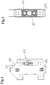
- Figure 1 shows a side view of the vertical vibrator according to the invention, as it is used in particular in civil engineering for the installation of vibro-filled columns or sheet pile walls.
- the vibrator can be suitable for normal frequency or high frequency vibration for vibrating in the steel profiles.
- the illustration shows the pulling yoke 10, on the back of which a guide rail 11 is formed.
- the pulling yoke 10 can be attached vertically to a leader of a suitable construction machine as an attachment tool.
- the exciter cell 20 protrudes from the lower end of the pulling yoke 10.
- the vibrator clamp which is usually attached to the protruding underside of the exciter cell 20 for clamping a steel profile to be vibrated in.
- one or more excitation cell shafts are mounted, preferably aligned parallel to one another, each of which is rotatably mounted and comprises eccentrically mounted unbalanced masses, which generate the desired vibration movement through the rotation of the excitation shafts.
- An integrated drive preferably of a hydraulic type, is provided for the rotation movement.
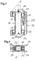
- vibration in the direction of the ramming axis is particularly desirable, which can be seen, for example, in the sectional views of the Figures 3,4 marked with the reference symbol A.
- the ramming axis A extends parallel to the leader in the assembly and operating position of the vibrator.
- the undesirable transverse accelerations and transverse forces transverse to the ramming axis are to be reduced by supporting the excitation cell 20 within the pulling yoke 10 via a symmetrical arrangement of elastomer bearings 30.
- These bearings 30 serve as bearing points and attachment points for the excitation cell 20 within the pulling yoke 10.
- these cuboid-shaped elastomer bearings 30 are arranged symmetrically to the ramming axis A, whereby the undesirable transverse forces and transverse movements can be optimally dampened. This results in an almost optimal vibration decoupling of the excitation cell 20 within the drawing yoke 10.
- Symmetrical mounting of the excitation cell 20 here explicitly refers to the double-symmetrical suspension of the excitation cell 20 in the drawing yoke 10. This means that the excitation cell 20 is mounted symmetrically in relation to two cutting planes along the ramming axis in a vibration-damping manner. One of these cutting planes is the ramming plane and the other cutting plane is a plane rotated by 90° to the ramming plane around the ramming axis.
- the bearing concept provides for the excitation cell 20 to be mounted at the top and bottom of the drawing yoke 10. This special arrangement of the bearing serves to reduce the vibrations that do not run along the ramming axis. This is necessary in order to achieve as single-axis a movement as possible of the excitation cell 20 along the ramming axis in the drawing yoke 10.
- sliding guides 40 are available for the vibration movement of the excitation cell 20 in the direction of the ramming axis A, with two sliding guides 40 being firmly connected to the excitation cell 20 on each side surface of the excitation cell 20.
- the sliding guides 40 are located on the center plane or ramming plane. Since the drawing yoke 10 is usually a steel construction and the sliding guides slide along this steel construction, a very hard and wear-resistant material must be selected for the sliding guides 40. For this reason, the sliding guides 40 are made of technical ceramic.
- the sliding guides 40 are provided with a tribologically optimized geometry in order to reduce the contact surface between the sliding guide 40 and the drawing yoke 10 sliding along it to a minimum.
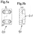
- a surface contour of the sliding guide 40 is provided with the Figure 5b
- the surface 41 represents the sliding partner of the guide, which runs along the Drawing yoke 10 slides.
- Figure 5a shows a top view of the sliding guide 40 mounted on the excitation cell 20, while Figure 5b shows a sectional view through the sliding guide along the cutting axis BB.
- the fixed mounting on the excitation cell 20 is carried out by means of screwing.
- the core idea of the invention is to reduce the relative movements of the excitation cell 20 in the transverse direction to the ramming axis A by symmetrically attaching the elastomer bearings 30. This reduces transverse accelerations and transverse forces, which reduces the load on the sliding guide 40 and makes the energy saved available for the regular, vertical movement.
- an optimized geometric shape 41 of the sliding guide 40 reduces the contact area between the bodies 10, 20 moving relative to one another, which reduces the friction that occurs and the energy dissipated as a result.
- the sliding guides 40 are placed on the ramming plane.
- wear is to be reduced by using technical ceramics for a sliding partner of the sliding guide 40. This significantly increases the service life of the sliding guides 40.
Landscapes
- Engineering & Computer Science (AREA)
- Structural Engineering (AREA)
- Life Sciences & Earth Sciences (AREA)
- Civil Engineering (AREA)
- General Life Sciences & Earth Sciences (AREA)
- Mining & Mineral Resources (AREA)
- Paleontology (AREA)
- General Engineering & Computer Science (AREA)
- Soil Sciences (AREA)
- Environmental & Geological Engineering (AREA)
- Agronomy & Crop Science (AREA)
- Placing Or Removing Of Piles Or Sheet Piles, Or Accessories Thereof (AREA)
- Apparatuses For Generation Of Mechanical Vibrations (AREA)
Claims (8)
- Vibrateur vertical qui peut être fixé de manière déplaçable verticalement à une jumelle d'une machine de construction, comportant un étrier de traction (10) pour monter le vibrateur vertical sur la jumelle de la machine de construction et une cellule d'excitation (20) montée sur l'étrier de traction (10) pour générer les vibrations, dans lequel un agencement de composants de palier élastiques (30) symétrique par rapport à l'axe de l'enfoncement de pieux (A) de la cellule d'excitation (20) est prévu pour le montage à découplage vibratoire de la cellule d'excitation (20) sur l'étrier de traction (10) afin de réduire les mouvements relatifs de la cellule d'excitation (20) transversalement à l'axe de l'enfoncement de pieux (A), la cellule d'excitation (20) étant montée à ses extrémités inférieure et supérieure, vue dans la direction de l'enfoncement de pieux (A), par au moins un composant de palier (30) par rapport à l'étrier de traction (10),
caractérisé
en ce qu'au moins une glissière (40) est prévue pour le guidage coulissant de la cellule d'excitation (20) dans la direction de vibration ou de l'enfoncement de pieux (A), et en ce que la cellule d'excitation (20) présente une section transversale essentiellement rectangulaire et deux composants de palier élastiques (30) sont respectivement prévus sur la face avant et la face arrière de la zone supérieure et de la zone inférieure de la cellule d'excitation (20), qui forment les points de palier de la cellule d'excitation (20) à l'intérieur de l'étrier de traction (10). - Vibrateur vertical selon la revendication 1, caractérisé en ce que les composants de palier élastiques (30) sont constitués par un élastomère ou comportent un élastomère.
- Vibrateur vertical selon l'une quelconque des revendications précédentes, caractérisé en ce que deux glissières (40) sont montées sur chaque surface latérale du vibrateur vertical, en particulier une glissière (40) chacune sur la zone supérieure et inférieure entre la cellule d'excitation (20) et l'étrier de traction (10).
- Vibrateur vertical selon l'une quelconque des revendications précédentes, caractérisé en ce qu'une ou plusieurs, de préférence toutes les glissières (40) se trouvent sur le plan central de la masse en mouvement de la cellule d'excitation (20) ou sont agencées symétriquement par rapport au plan central.
- Vibrateur vertical selon l'une quelconque des revendications précédentes, caractérisé en ce que les une ou plusieurs glissières (40) possèdent une géométrie tribologiquement optimisée.
- Vibrateur vertical selon la revendication 5, caractérisé en ce que les une ou plusieurs glissières (40) comportent au moins une surface de contact convexe qui est en contact avec la partie guidée, c'est-à-dire avec l'étrier de traction (10) et/ou la cellule d'excitation (20).
- Vibrateur vertical selon l'une quelconque des revendications précédentes, caractérisé en ce qu'au moins un partenaire de glissement de l'une ou plusieurs glissières (40) est constitué au moins partiellement de céramique technique ou en comprend.
- Machine de construction comportant un vibrateur vertical selon l'une quelconque des revendications précédentes.
Applications Claiming Priority (1)
| Application Number | Priority Date | Filing Date | Title |
|---|---|---|---|
| DE202015001862.9U DE202015001862U1 (de) | 2015-03-10 | 2015-03-10 | Rüttler als Anbaugerät für eine Baumaschine |
Publications (3)
| Publication Number | Publication Date |
|---|---|
| EP3067470A1 EP3067470A1 (fr) | 2016-09-14 |
| EP3067470B1 EP3067470B1 (fr) | 2020-12-09 |
| EP3067470B2 true EP3067470B2 (fr) | 2024-11-27 |
Family
ID=55532147
Family Applications (1)
| Application Number | Title | Priority Date | Filing Date |
|---|---|---|---|
| EP16159103.7A Active EP3067470B2 (fr) | 2015-03-10 | 2016-03-08 | Vibreur vertical et machine de construction avec un vibreur vertical |
Country Status (2)
| Country | Link |
|---|---|
| EP (1) | EP3067470B2 (fr) |
| DE (1) | DE202015001862U1 (fr) |
Families Citing this family (3)
| Publication number | Priority date | Publication date | Assignee | Title |
|---|---|---|---|---|
| CN113323039A (zh) * | 2021-06-15 | 2021-08-31 | 温州超泽天硕智能科技有限公司 | 一种自平衡桩基检测装置 |
| KR20230002160A (ko) * | 2022-12-09 | 2023-01-05 | (주) 대동이엔지 | 정밀 수직시공 시스템을 가진 파일 드라이버 |
| EP4675047A1 (fr) * | 2024-07-03 | 2026-01-07 | ABI Anlagentechnik-Baumaschinen-Industriebedarf Maschinenfabrik und Vertriebsgesellschaft mbH | Générateur de vibrations pour sonnettes mécaniques vibrantes |
Family Cites Families (6)
| Publication number | Priority date | Publication date | Assignee | Title |
|---|---|---|---|---|
| FR2527667A1 (fr) * | 1982-05-27 | 1983-12-02 | Procedes Tech Const | Dispositif amovible de traction supplementaire pour appareil de foncage et/ou arrachage par vibration |
| DE8507086U1 (de) * | 1985-03-12 | 1985-04-25 | Krings International GmbH & Co KG, 5138 Heinsberg | Vibrationsramme für den Grabenverbau |
| US7080958B1 (en) * | 2005-04-27 | 2006-07-25 | International Construction Equipment, Inc. | Vibratory pile driver/extractor with two-stage vibration/tension load suppressor |
| US8342778B2 (en) * | 2009-04-16 | 2013-01-01 | Hercules Machinery Corporation | Method and apparatus for facilitating the subterranean support of underground conduits having a fixed insertion axis |
| US8096733B2 (en) * | 2009-07-10 | 2012-01-17 | Hercules Machinery Corporation | Apparatus for inserting sheet pile having an independently adjustable insertion axis and method for using the same |
| EP2444553B1 (fr) * | 2010-10-20 | 2012-12-05 | ABI Anlagentechnik-Baumaschinen-Industriebedarf Maschinenfabrik und Vertriebsgesellschaft mbH | Dispositif de battage et de traction |
-
2015
- 2015-03-10 DE DE202015001862.9U patent/DE202015001862U1/de not_active Expired - Lifetime
-
2016
- 2016-03-08 EP EP16159103.7A patent/EP3067470B2/fr active Active
Non-Patent Citations (1)
| Title |
|---|
| Vorbenutzung "Speedram 7500/1" † |
Also Published As
| Publication number | Publication date |
|---|---|
| DE202015001862U1 (de) | 2016-06-13 |
| EP3067470A1 (fr) | 2016-09-14 |
| EP3067470B1 (fr) | 2020-12-09 |
Similar Documents
| Publication | Publication Date | Title |
|---|---|---|
| DE102012111838B4 (de) | Prüfstand für ein Rotorblatt, Anordnung mit einem derartigen Prüfstand und Verfahren zum Betreiben eines derartigen Prüfstands | |
| EP0116164B1 (fr) | Appareil de battage par vibration | |
| DE3433797C2 (fr) | ||
| EP2558649A2 (fr) | Agencement pour fournir une force de pression pulsée | |
| EP3067470B2 (fr) | Vibreur vertical et machine de construction avec un vibreur vertical | |
| DE10355172B3 (de) | Verdichtervorrichtung eines Baggers | |
| DE102012025649A1 (de) | Prüfstand für ein Rotorblatt, Anordnung mit einem derartigen Prüfstand und Verfahren zum Betreiben eines derartigen Prüfstands | |
| DE10057295A1 (de) | Vibrationen oder Schwingungen dämpfender Körper | |
| DE102004042369A1 (de) | Bodenbearbeitungsgerät und Verfahren zum Einbringen eines Arbeitselementes in den Boden | |
| EP1936037B1 (fr) | Compacteur de montage au vehicule | |
| DE102016105950A1 (de) | Bodenverdichtungsvorrichtung mit entkoppeltem Führungshandgriff | |
| EP4279659A1 (fr) | Appareil d'excavation de tranchées pour parois moulées et procédé d'excavation d'une paroi moulée dans le sol | |
| DE102007023963B4 (de) | Vorrichtung für einen Schwingungserreger | |
| EP3215678B1 (fr) | Vibrofonceur | |
| DE102012220163A1 (de) | Schwenkeinrichtung zum Aufnehmen eines Prüfstandes | |
| EP2530205B1 (fr) | Procédé de pose verticale d'un tuyau et dispositif d'armature pour ce faire | |
| EP3237687B1 (fr) | Amortisseur de vibrations pour articulation d'accouplement d'un dispositif de vibration en profondeur | |
| EP1957715A1 (fr) | Plaque vibrante dotee d'un dispositif de stabilisation | |
| DE102012022147A1 (de) | Vorrichtung zum Anpassen der Position des Elektromotors an die Stellung der Antriebstrommel eines Direktantriebs für eine Gurtförderanlage | |
| DE102005024367B4 (de) | Seismische Quelle und Verfahren zur Erzeugung seismischer Scherwellen | |
| EP4467723B1 (fr) | Dispositif d'introduction pour introduire un élément de fondation | |
| DE69201124T2 (de) | Elastische Aufhängungsvorrichtung mit verschiedenen Steifheiten zur Lagerung eines Geräts. | |
| EP1411175A2 (fr) | Dispositif pour compacter le sol | |
| DE10115107A1 (de) | Tiefenrüttler | |
| DE102004014722B3 (de) | Seismische Quelle und Verfahren zur Erzeugung seismischer Schwingungen |
Legal Events
| Date | Code | Title | Description |
|---|---|---|---|
| PUAI | Public reference made under article 153(3) epc to a published international application that has entered the european phase |
Free format text: ORIGINAL CODE: 0009012 |
|
| 17P | Request for examination filed |
Effective date: 20160718 |
|
| AK | Designated contracting states |
Kind code of ref document: A1 Designated state(s): AL AT BE BG CH CY CZ DE DK EE ES FI FR GB GR HR HU IE IS IT LI LT LU LV MC MK MT NL NO PL PT RO RS SE SI SK SM TR |
|
| AX | Request for extension of the european patent |
Extension state: BA ME |
|
| STAA | Information on the status of an ep patent application or granted ep patent |
Free format text: STATUS: EXAMINATION IS IN PROGRESS |
|
| 17Q | First examination report despatched |
Effective date: 20180727 |
|
| REG | Reference to a national code |
Ref country code: DE Ref legal event code: R079 Ref document number: 502016011892 Country of ref document: DE Free format text: PREVIOUS MAIN CLASS: E02D0007180000 Ipc: E02D0003074000 |
|
| GRAP | Despatch of communication of intention to grant a patent |
Free format text: ORIGINAL CODE: EPIDOSNIGR1 |
|
| STAA | Information on the status of an ep patent application or granted ep patent |
Free format text: STATUS: GRANT OF PATENT IS INTENDED |
|
| RIC1 | Information provided on ipc code assigned before grant |
Ipc: E02D 3/074 20060101AFI20200615BHEP |
|
| INTG | Intention to grant announced |
Effective date: 20200703 |
|
| GRAS | Grant fee paid |
Free format text: ORIGINAL CODE: EPIDOSNIGR3 |
|
| GRAA | (expected) grant |
Free format text: ORIGINAL CODE: 0009210 |
|
| STAA | Information on the status of an ep patent application or granted ep patent |
Free format text: STATUS: THE PATENT HAS BEEN GRANTED |
|
| AK | Designated contracting states |
Kind code of ref document: B1 Designated state(s): AL AT BE BG CH CY CZ DE DK EE ES FI FR GB GR HR HU IE IS IT LI LT LU LV MC MK MT NL NO PL PT RO RS SE SI SK SM TR |
|
| REG | Reference to a national code |
Ref country code: GB Ref legal event code: FG4D Free format text: NOT ENGLISH |
|
| REG | Reference to a national code |
Ref country code: AT Ref legal event code: REF Ref document number: 1343583 Country of ref document: AT Kind code of ref document: T Effective date: 20201215 Ref country code: CH Ref legal event code: EP |
|
| REG | Reference to a national code |
Ref country code: DE Ref legal event code: R096 Ref document number: 502016011892 Country of ref document: DE |
|
| REG | Reference to a national code |
Ref country code: IE Ref legal event code: FG4D Free format text: LANGUAGE OF EP DOCUMENT: GERMAN |
|
| REG | Reference to a national code |
Ref country code: NL Ref legal event code: FP |
|
| PG25 | Lapsed in a contracting state [announced via postgrant information from national office to epo] |
Ref country code: RS Free format text: LAPSE BECAUSE OF FAILURE TO SUBMIT A TRANSLATION OF THE DESCRIPTION OR TO PAY THE FEE WITHIN THE PRESCRIBED TIME-LIMIT Effective date: 20201209 Ref country code: FI Free format text: LAPSE BECAUSE OF FAILURE TO SUBMIT A TRANSLATION OF THE DESCRIPTION OR TO PAY THE FEE WITHIN THE PRESCRIBED TIME-LIMIT Effective date: 20201209 Ref country code: NO Free format text: LAPSE BECAUSE OF FAILURE TO SUBMIT A TRANSLATION OF THE DESCRIPTION OR TO PAY THE FEE WITHIN THE PRESCRIBED TIME-LIMIT Effective date: 20210309 Ref country code: GR Free format text: LAPSE BECAUSE OF FAILURE TO SUBMIT A TRANSLATION OF THE DESCRIPTION OR TO PAY THE FEE WITHIN THE PRESCRIBED TIME-LIMIT Effective date: 20210310 |
|
| PG25 | Lapsed in a contracting state [announced via postgrant information from national office to epo] |
Ref country code: BG Free format text: LAPSE BECAUSE OF FAILURE TO SUBMIT A TRANSLATION OF THE DESCRIPTION OR TO PAY THE FEE WITHIN THE PRESCRIBED TIME-LIMIT Effective date: 20210309 Ref country code: SE Free format text: LAPSE BECAUSE OF FAILURE TO SUBMIT A TRANSLATION OF THE DESCRIPTION OR TO PAY THE FEE WITHIN THE PRESCRIBED TIME-LIMIT Effective date: 20201209 Ref country code: LV Free format text: LAPSE BECAUSE OF FAILURE TO SUBMIT A TRANSLATION OF THE DESCRIPTION OR TO PAY THE FEE WITHIN THE PRESCRIBED TIME-LIMIT Effective date: 20201209 |
|
| PG25 | Lapsed in a contracting state [announced via postgrant information from national office to epo] |
Ref country code: HR Free format text: LAPSE BECAUSE OF FAILURE TO SUBMIT A TRANSLATION OF THE DESCRIPTION OR TO PAY THE FEE WITHIN THE PRESCRIBED TIME-LIMIT Effective date: 20201209 |
|
| REG | Reference to a national code |
Ref country code: LT Ref legal event code: MG9D |
|
| PG25 | Lapsed in a contracting state [announced via postgrant information from national office to epo] |
Ref country code: PT Free format text: LAPSE BECAUSE OF FAILURE TO SUBMIT A TRANSLATION OF THE DESCRIPTION OR TO PAY THE FEE WITHIN THE PRESCRIBED TIME-LIMIT Effective date: 20210409 Ref country code: SK Free format text: LAPSE BECAUSE OF FAILURE TO SUBMIT A TRANSLATION OF THE DESCRIPTION OR TO PAY THE FEE WITHIN THE PRESCRIBED TIME-LIMIT Effective date: 20201209 Ref country code: RO Free format text: LAPSE BECAUSE OF FAILURE TO SUBMIT A TRANSLATION OF THE DESCRIPTION OR TO PAY THE FEE WITHIN THE PRESCRIBED TIME-LIMIT Effective date: 20201209 Ref country code: CZ Free format text: LAPSE BECAUSE OF FAILURE TO SUBMIT A TRANSLATION OF THE DESCRIPTION OR TO PAY THE FEE WITHIN THE PRESCRIBED TIME-LIMIT Effective date: 20201209 Ref country code: EE Free format text: LAPSE BECAUSE OF FAILURE TO SUBMIT A TRANSLATION OF THE DESCRIPTION OR TO PAY THE FEE WITHIN THE PRESCRIBED TIME-LIMIT Effective date: 20201209 Ref country code: SM Free format text: LAPSE BECAUSE OF FAILURE TO SUBMIT A TRANSLATION OF THE DESCRIPTION OR TO PAY THE FEE WITHIN THE PRESCRIBED TIME-LIMIT Effective date: 20201209 Ref country code: LT Free format text: LAPSE BECAUSE OF FAILURE TO SUBMIT A TRANSLATION OF THE DESCRIPTION OR TO PAY THE FEE WITHIN THE PRESCRIBED TIME-LIMIT Effective date: 20201209 |
|
| REG | Reference to a national code |
Ref country code: DE Ref legal event code: R026 Ref document number: 502016011892 Country of ref document: DE |
|
| PLBI | Opposition filed |
Free format text: ORIGINAL CODE: 0009260 |
|
| PG25 | Lapsed in a contracting state [announced via postgrant information from national office to epo] |
Ref country code: PL Free format text: LAPSE BECAUSE OF FAILURE TO SUBMIT A TRANSLATION OF THE DESCRIPTION OR TO PAY THE FEE WITHIN THE PRESCRIBED TIME-LIMIT Effective date: 20201209 |
|
| 26 | Opposition filed |
Opponent name: ABI ANLAGENTECHNIK-BAUMASCHINEN-INDUSTRIEBEDARF MASCHINENFABRIK UND VERTRIEBSGESELLSCHAFT MBH Effective date: 20210730 |
|
| PLAX | Notice of opposition and request to file observation + time limit sent |
Free format text: ORIGINAL CODE: EPIDOSNOBS2 |
|
| PG25 | Lapsed in a contracting state [announced via postgrant information from national office to epo] |
Ref country code: IS Free format text: LAPSE BECAUSE OF FAILURE TO SUBMIT A TRANSLATION OF THE DESCRIPTION OR TO PAY THE FEE WITHIN THE PRESCRIBED TIME-LIMIT Effective date: 20210409 |
|
| PG25 | Lapsed in a contracting state [announced via postgrant information from national office to epo] |
Ref country code: MC Free format text: LAPSE BECAUSE OF FAILURE TO SUBMIT A TRANSLATION OF THE DESCRIPTION OR TO PAY THE FEE WITHIN THE PRESCRIBED TIME-LIMIT Effective date: 20201209 Ref country code: AL Free format text: LAPSE BECAUSE OF FAILURE TO SUBMIT A TRANSLATION OF THE DESCRIPTION OR TO PAY THE FEE WITHIN THE PRESCRIBED TIME-LIMIT Effective date: 20201209 Ref country code: IT Free format text: LAPSE BECAUSE OF FAILURE TO SUBMIT A TRANSLATION OF THE DESCRIPTION OR TO PAY THE FEE WITHIN THE PRESCRIBED TIME-LIMIT Effective date: 20201209 |
|
| REG | Reference to a national code |
Ref country code: CH Ref legal event code: PL |
|
| GBPC | Gb: european patent ceased through non-payment of renewal fee |
Effective date: 20210309 |
|
| PG25 | Lapsed in a contracting state [announced via postgrant information from national office to epo] |
Ref country code: ES Free format text: LAPSE BECAUSE OF FAILURE TO SUBMIT A TRANSLATION OF THE DESCRIPTION OR TO PAY THE FEE WITHIN THE PRESCRIBED TIME-LIMIT Effective date: 20201209 Ref country code: DK Free format text: LAPSE BECAUSE OF FAILURE TO SUBMIT A TRANSLATION OF THE DESCRIPTION OR TO PAY THE FEE WITHIN THE PRESCRIBED TIME-LIMIT Effective date: 20201209 Ref country code: SI Free format text: LAPSE BECAUSE OF FAILURE TO SUBMIT A TRANSLATION OF THE DESCRIPTION OR TO PAY THE FEE WITHIN THE PRESCRIBED TIME-LIMIT Effective date: 20201209 |
|
| REG | Reference to a national code |
Ref country code: BE Ref legal event code: MM Effective date: 20210331 |
|
| PLBB | Reply of patent proprietor to notice(s) of opposition received |
Free format text: ORIGINAL CODE: EPIDOSNOBS3 |
|
| PG25 | Lapsed in a contracting state [announced via postgrant information from national office to epo] |
Ref country code: IE Free format text: LAPSE BECAUSE OF NON-PAYMENT OF DUE FEES Effective date: 20210308 Ref country code: GB Free format text: LAPSE BECAUSE OF NON-PAYMENT OF DUE FEES Effective date: 20210309 Ref country code: LU Free format text: LAPSE BECAUSE OF NON-PAYMENT OF DUE FEES Effective date: 20210308 Ref country code: LI Free format text: LAPSE BECAUSE OF NON-PAYMENT OF DUE FEES Effective date: 20210331 Ref country code: CH Free format text: LAPSE BECAUSE OF NON-PAYMENT OF DUE FEES Effective date: 20210331 |
|
| PG25 | Lapsed in a contracting state [announced via postgrant information from national office to epo] |
Ref country code: IS Free format text: LAPSE BECAUSE OF FAILURE TO SUBMIT A TRANSLATION OF THE DESCRIPTION OR TO PAY THE FEE WITHIN THE PRESCRIBED TIME-LIMIT Effective date: 20210409 |
|
| PG25 | Lapsed in a contracting state [announced via postgrant information from national office to epo] |
Ref country code: BE Free format text: LAPSE BECAUSE OF NON-PAYMENT OF DUE FEES Effective date: 20210331 |
|
| PG25 | Lapsed in a contracting state [announced via postgrant information from national office to epo] |
Ref country code: HU Free format text: LAPSE BECAUSE OF FAILURE TO SUBMIT A TRANSLATION OF THE DESCRIPTION OR TO PAY THE FEE WITHIN THE PRESCRIBED TIME-LIMIT; INVALID AB INITIO Effective date: 20160308 |
|
| PG25 | Lapsed in a contracting state [announced via postgrant information from national office to epo] |
Ref country code: CY Free format text: LAPSE BECAUSE OF FAILURE TO SUBMIT A TRANSLATION OF THE DESCRIPTION OR TO PAY THE FEE WITHIN THE PRESCRIBED TIME-LIMIT Effective date: 20201209 |
|
| P01 | Opt-out of the competence of the unified patent court (upc) registered |
Effective date: 20230630 |
|
| PG25 | Lapsed in a contracting state [announced via postgrant information from national office to epo] |
Ref country code: MK Free format text: LAPSE BECAUSE OF FAILURE TO SUBMIT A TRANSLATION OF THE DESCRIPTION OR TO PAY THE FEE WITHIN THE PRESCRIBED TIME-LIMIT Effective date: 20201209 |
|
| PG25 | Lapsed in a contracting state [announced via postgrant information from national office to epo] |
Ref country code: TR Free format text: LAPSE BECAUSE OF FAILURE TO SUBMIT A TRANSLATION OF THE DESCRIPTION OR TO PAY THE FEE WITHIN THE PRESCRIBED TIME-LIMIT Effective date: 20201209 |
|
| REG | Reference to a national code |
Ref country code: CH Ref legal event code: PK Free format text: TITEL |
|
| PG25 | Lapsed in a contracting state [announced via postgrant information from national office to epo] |
Ref country code: MT Free format text: LAPSE BECAUSE OF FAILURE TO SUBMIT A TRANSLATION OF THE DESCRIPTION OR TO PAY THE FEE WITHIN THE PRESCRIBED TIME-LIMIT Effective date: 20201209 |
|
| PUAH | Patent maintained in amended form |
Free format text: ORIGINAL CODE: 0009272 |
|
| STAA | Information on the status of an ep patent application or granted ep patent |
Free format text: STATUS: PATENT MAINTAINED AS AMENDED |
|
| 27A | Patent maintained in amended form |
Effective date: 20241127 |
|
| AK | Designated contracting states |
Kind code of ref document: B2 Designated state(s): AL AT BE BG CH CY CZ DE DK EE ES FI FR GB GR HR HU IE IS IT LI LT LU LV MC MK MT NL NO PL PT RO RS SE SI SK SM TR |
|
| REG | Reference to a national code |
Ref country code: DE Ref legal event code: R102 Ref document number: 502016011892 Country of ref document: DE |
|
| REG | Reference to a national code |
Ref country code: NL Ref legal event code: FP |
|
| PGFP | Annual fee paid to national office [announced via postgrant information from national office to epo] |
Ref country code: DE Payment date: 20250331 Year of fee payment: 10 |
|
| PGFP | Annual fee paid to national office [announced via postgrant information from national office to epo] |
Ref country code: AT Payment date: 20260319 Year of fee payment: 11 |
|
| PGFP | Annual fee paid to national office [announced via postgrant information from national office to epo] |
Ref country code: NL Payment date: 20260330 Year of fee payment: 11 |
|
| PGFP | Annual fee paid to national office [announced via postgrant information from national office to epo] |
Ref country code: FR Payment date: 20260330 Year of fee payment: 11 |