EP3067471A1 - Verfahren zur modifizierung thermischer leistung und kühlsystem - Google Patents
Verfahren zur modifizierung thermischer leistung und kühlsystem Download PDFInfo
- Publication number
- EP3067471A1 EP3067471A1 EP15305372.3A EP15305372A EP3067471A1 EP 3067471 A1 EP3067471 A1 EP 3067471A1 EP 15305372 A EP15305372 A EP 15305372A EP 3067471 A1 EP3067471 A1 EP 3067471A1
- Authority
- EP
- European Patent Office
- Prior art keywords
- thermal conductivity
- region
- doped
- cooling system
- thermally conductive
- Prior art date
- Legal status (The legal status is an assumption and is not a legal conclusion. Google has not performed a legal analysis and makes no representation as to the accuracy of the status listed.)
- Withdrawn
Links
- 238000000034 method Methods 0.000 title claims abstract description 22
- 238000001816 cooling Methods 0.000 title claims description 21
- 239000000463 material Substances 0.000 claims abstract description 115
- 238000000926 separation method Methods 0.000 claims abstract description 16
- 239000002689 soil Substances 0.000 claims description 33
- 239000011159 matrix material Substances 0.000 claims description 15
- 229910052751 metal Inorganic materials 0.000 claims description 13
- 239000002184 metal Substances 0.000 claims description 13
- 239000004576 sand Substances 0.000 claims description 12
- 239000012782 phase change material Substances 0.000 claims description 9
- 239000012528 membrane Substances 0.000 claims description 6
- XLYOFNOQVPJJNP-UHFFFAOYSA-N water Substances O XLYOFNOQVPJJNP-UHFFFAOYSA-N 0.000 claims description 6
- 230000004888 barrier function Effects 0.000 claims description 5
- 239000006262 metallic foam Substances 0.000 claims description 3
- 239000000047 product Substances 0.000 description 21
- 239000000654 additive Substances 0.000 description 6
- 238000012546 transfer Methods 0.000 description 6
- RYGMFSIKBFXOCR-UHFFFAOYSA-N Copper Chemical compound [Cu] RYGMFSIKBFXOCR-UHFFFAOYSA-N 0.000 description 5
- 241001465754 Metazoa Species 0.000 description 5
- 230000000996 additive effect Effects 0.000 description 5
- 229910052802 copper Inorganic materials 0.000 description 5
- 239000010949 copper Substances 0.000 description 5
- 238000010521 absorption reaction Methods 0.000 description 4
- 239000003570 air Substances 0.000 description 3
- 239000000835 fiber Substances 0.000 description 3
- -1 hardcore Substances 0.000 description 3
- 239000000203 mixture Substances 0.000 description 3
- 239000004677 Nylon Substances 0.000 description 2
- 239000004567 concrete Substances 0.000 description 2
- 239000002019 doping agent Substances 0.000 description 2
- 230000000694 effects Effects 0.000 description 2
- 239000004744 fabric Substances 0.000 description 2
- 239000006260 foam Substances 0.000 description 2
- 230000001965 increasing effect Effects 0.000 description 2
- 238000012423 maintenance Methods 0.000 description 2
- 230000005012 migration Effects 0.000 description 2
- 238000013508 migration Methods 0.000 description 2
- 229920001778 nylon Polymers 0.000 description 2
- 239000004743 Polypropylene Substances 0.000 description 1
- 230000002745 absorbent Effects 0.000 description 1
- 239000002250 absorbent Substances 0.000 description 1
- 239000000853 adhesive Substances 0.000 description 1
- 230000001070 adhesive effect Effects 0.000 description 1
- 239000004411 aluminium Substances 0.000 description 1
- 229910052782 aluminium Inorganic materials 0.000 description 1
- XAGFODPZIPBFFR-UHFFFAOYSA-N aluminium Chemical compound [Al] XAGFODPZIPBFFR-UHFFFAOYSA-N 0.000 description 1
- 239000012080 ambient air Substances 0.000 description 1
- 230000003466 anti-cipated effect Effects 0.000 description 1
- 230000008901 benefit Effects 0.000 description 1
- 239000013590 bulk material Substances 0.000 description 1
- 239000004568 cement Substances 0.000 description 1
- 230000008859 change Effects 0.000 description 1
- 239000004927 clay Substances 0.000 description 1
- 239000011248 coating agent Substances 0.000 description 1
- 238000000576 coating method Methods 0.000 description 1
- 238000004891 communication Methods 0.000 description 1
- 239000004020 conductor Substances 0.000 description 1
- 238000005516 engineering process Methods 0.000 description 1
- 230000002708 enhancing effect Effects 0.000 description 1
- 230000004927 fusion Effects 0.000 description 1
- 230000017525 heat dissipation Effects 0.000 description 1
- 230000006872 improvement Effects 0.000 description 1
- 238000012986 modification Methods 0.000 description 1
- 230000004048 modification Effects 0.000 description 1
- 239000002991 molded plastic Substances 0.000 description 1
- 238000013021 overheating Methods 0.000 description 1
- 239000012188 paraffin wax Substances 0.000 description 1
- 239000012466 permeate Substances 0.000 description 1
- 230000000704 physical effect Effects 0.000 description 1
- 229920000642 polymer Polymers 0.000 description 1
- 229920000098 polyolefin Polymers 0.000 description 1
- 229920001155 polypropylene Polymers 0.000 description 1
- 230000008569 process Effects 0.000 description 1
- 239000007787 solid Substances 0.000 description 1
- 230000001960 triggered effect Effects 0.000 description 1
- 239000002023 wood Substances 0.000 description 1
Images


Classifications
-
- H—ELECTRICITY
- H05—ELECTRIC TECHNIQUES NOT OTHERWISE PROVIDED FOR
- H05K—PRINTED CIRCUITS; CASINGS OR CONSTRUCTIONAL DETAILS OF ELECTRIC APPARATUS; MANUFACTURE OF ASSEMBLAGES OF ELECTRICAL COMPONENTS
- H05K7/00—Constructional details common to different types of electric apparatus
- H05K7/20—Modifications to facilitate cooling, ventilating, or heating
- H05K7/2039—Modifications to facilitate cooling, ventilating, or heating characterised by the heat transfer by conduction from the heat generating element to a dissipating body
-
- E—FIXED CONSTRUCTIONS
- E02—HYDRAULIC ENGINEERING; FOUNDATIONS; SOIL SHIFTING
- E02D—FOUNDATIONS; EXCAVATIONS; EMBANKMENTS; UNDERGROUND OR UNDERWATER STRUCTURES
- E02D29/00—Independent underground or underwater structures; Retaining walls
- E02D29/12—Manhole shafts; Other inspection or access chambers; Accessories therefor
-
- G—PHYSICS
- G02—OPTICS
- G02B—OPTICAL ELEMENTS, SYSTEMS OR APPARATUS
- G02B6/00—Light guides; Structural details of arrangements comprising light guides and other optical elements, e.g. couplings
- G02B6/46—Processes or apparatus adapted for installing or repairing optical fibres or optical cables
- G02B6/50—Underground or underwater installation; Installation through tubing, conduits or ducts
- G02B6/501—Underground or underwater installation; Installation through tubing, conduits or ducts underground installation of connection boxes
-
- H—ELECTRICITY
- H05—ELECTRIC TECHNIQUES NOT OTHERWISE PROVIDED FOR
- H05K—PRINTED CIRCUITS; CASINGS OR CONSTRUCTIONAL DETAILS OF ELECTRIC APPARATUS; MANUFACTURE OF ASSEMBLAGES OF ELECTRICAL COMPONENTS
- H05K7/00—Constructional details common to different types of electric apparatus
- H05K7/20—Modifications to facilitate cooling, ventilating, or heating
- H05K7/2039—Modifications to facilitate cooling, ventilating, or heating characterised by the heat transfer by conduction from the heat generating element to a dissipating body
- H05K7/20436—Inner thermal coupling elements in heat dissipating housings, e.g. protrusions or depressions integrally formed in the housing
- H05K7/20445—Inner thermal coupling elements in heat dissipating housings, e.g. protrusions or depressions integrally formed in the housing the coupling element being an additional piece, e.g. thermal standoff
- H05K7/20463—Filling compound, e.g. potted resin
Definitions
- aspects relate, in general, to a cooling system and a method for cooling an underground electronic apparatus.
- Future deployment of next generation telecommunications infrastructures aims to bring fibre as close to the end user as possible.
- Current fixed access devices are typically placed in cavities beneath ground level such as in man-holes or even smaller hand-holes before being split to multiple end users.
- an electronic apparatus such as a router that receives a broadband signal from a fibre-based infrastructure can be used to split off a broadband signal for multiple end users over traditional cabling, such as copper cabling for example.
- the current method of deployment involves digging a hole and building or inserting a structure into the hole. This could be a concrete enclosure or a moulded plastic structure. Both have access through a surface opening that can be sealed closed.
- Next generation deployment is anticipated to take place directly in the ground outside each and every home with a single unit serving a single home.
- the connection to the home is made and a subscriber upgrades to the high bandwidth provided by such a device when they are ready.
- An example of such a technology is a telecoms node or broadband router device which can provide fibre speeds over relatively short lengths of copper wires, hence the deployment close to individual homes.
- the electronic apparatus used to provide services, such as broadband will likely be buried beneath ground in a small hole directly in the soil.
- a method for modifying thermal performance of an electronic apparatus deployed in a subterranean region including separating the region from surrounding subterranean material using a separation element, burying the apparatus in the region using doped material, the doped material comprising a first material having a first thermal conductivity doped with a second material having a second thermal conductivity, wherein a thermal conductivity of the second material is higher than the thermal conductivity of the first material to increase thermal performance of the first material.
- the doped material can be soil or sand and the separation element can be a lining, mesh or lattice.
- the method can include covering the apparatus in a thermally conductive matrix having a thermal conductivity which is higher than the thermal conductivity of the first material.
- the method can further include compressing the apparatus in the region, whereby to encase the apparatus in the thermally conductive matrix.
- the region can be covered with an insulated thermal barrier.
- the method can include deploying or installing an impermeable membrane at the base of the region to sit beneath the apparatus, whereby to collect or otherwise trap water.
- a cooling system for a subterranean electronic apparatus comprising a doped material, the doped material comprising a first material having a first thermal conductivity doped with a second material having a second thermal conductivity, wherein a thermal conductivity of the second material is higher than the thermal conductivity of the first material to increase thermal performance of the first material, the doped material being configured to receive the apparatus in a subterranean region separated from surrounding subterranean material using a separation element.
- the doped material can be soil or sand and the separation element can be a lining, mesh or lattice.
- the second material can include strands or pieces of metal and/or encapsulated phase change material.
- a thermally conductive matrix can be configured to cover the apparatus, the thermally conductive matrix having a thermal conductivity which is higher than the thermal conductivity of the first material.
- the thermally conductive matrix can be a metal foam.
- the thermally conductive matrix can be compressed around the apparatus to encase the apparatus.
- the region can be covered with an insulated thermal barrier.
- An impermeable membrane can be deployed or installed at the base of the region to sit beneath the apparatus, to collect or otherwise trap water.
- a support can be provided at the base of the region to support the apparatus within the region.
- Thermal management solutions for existing devices allow for the thermal load from an electronic apparatus to be dissipated into convecting air, however, this is not possible with the proposed subterranean method of deployment. This means the only mode of heat transport is conduction through the soil, which is problematic since soil has a poor thermal conductivity, and hence, poor heat removal capability.
- a method and system of increasing the thermal conductivity of the material surrounding an electronic apparatus deployed in the ground This enables the product to be deployed underground without overheating.
- the enhanced conductivity of the material effectively increases the available surface area over which the product can dissipate heat, which greatly enhances its thermal performance.
- materials, such as soil types vary considerably depending on the location, altitude and climate. This means that simply placing the product in the existing soil is not appropriate given the extent of variation.
- soil or other material within which an electronic apparatus is to be buried for deployment directly in the ground is doped with an additive to increase the thermal performance thereof. This can increase the thermal conductivity and/or thermal storage of the material to enhance its heat removal capability.
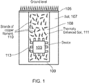
- FIG. 1 is a schematic representation of a cooling system according to an example.
- a subterranean electronic apparatus 103 is deployed below ground level 105.
- a hole is dug into the soil 107, or other subterranean material, which may include sand, clay, hardcore, cement, aggregate and the like or any combination thereof, such as a mixture of sand and soil for example to provide a subterranean region, generally depicted in lighter shade, which, in an example, is separated from surrounding subterranean material, generally depicted in darker shade, using a separation element 109. That is, an element is provided in a hole that has been excavated or dug out from the ground in order to separate material placed into (or to be placed into) the hole from surrounding material.
- the separation element 109 is provided against the walls and floor of the hole, and may be fixed in place using fixings such as rivets, screws, nails, dowels or adhesive and so on.
- the separation element 109 is resilient or semi-rigid and may therefore be maintained in a desired position without the use of any additional fixings.
- a separation element is a lining, mesh or lattice 109, which can be thermally conductive, such as a lining, mesh or lattice and so on made from encapsulated metal (encapsulated to protect the metal from moisture in the ground).
- the region can be dug out of the ground to a desired depth and width and so on, and the mesh 109 can be introduced into the hold to cover the bottom and/or sides of the hole, but leaving the opening at the top exposed to enable apparatus 103 and doped material 111 to be introduced into the lined hole forming the region.
- the apparatus 103 is buried in the hole using doped material 111.
- the doped material comprises a first material having a first thermal conductivity doped with a second material having a second thermal conductivity.
- a thermal conductivity of the second material is higher than the thermal conductivity of the first material to increase thermal performance of the first material.
- the doped material, that is the first material can be, for example soil or sand.
- the second material can be selected from one or more suitable materials as will be described below.
- the lining, mesh or lattice can act to reduce the tendency of the doped material 111 to dissipate over time, which may be exacerbated by ingress and egress of animals that may happen to live or pass through the region in question. That is, the thermally enhanced material 111 can be supported and maintained in position in the region using a mesh or lattice 109, or any other suitable structure or material such as webbing or netting, or a framework. Gaps provided in the mesh or lattice and so on can be selected in size and position in order to counteract the effects of animals which may otherwise try to pass into the enhanced region 111.
- a lattice or mesh can be provided with interstices, gaps or openings that are selected to be relatively small, such as of the order of 1-2mm so as to prevent ingress of animals but allow moisture to penetrate and/or escape.
- a fabric or permeable material can be used to line the hole within which the apparatus is to be deployed.
- a nylon weaved fabric or material may be used.
- the lining is relatively thin, such as of the order of several millimetres for example. As such, it presents a minimal resistance to heat transfer.
- the doped material 111 such as doped soil
- a thermally conductive or absorbent additive such as strands or pieces of metal, such as copper filaments for example.
- the apparatus 103 is covered with the material 111 in order to improve transfer of heat from the product to the surrounding non-enhanced material/soil 107.
- the thermally enhanced soil has been doped with long strands of copper filament, although any higher thermal conductivity material can be used.
- the filaments or pieces can be coated in a material to protect it from the elements. That is, the first material 108 can be soil and/or sand and so on, and the second material 110 can be strands or pieces of metal. The mixture of the first 108 and second 110 materials makes up the thermally enhanced material 111.
- a hole measuring 150mm in diameter and 500 mm deep could be dug and lined or otherwise provided with a thermally conductive mesh or lattice for the base and/or side(s) of the hole.
- Prepared material, such as soil, containing the additive would be poured in up to the level of about 100mm, then the product is placed on the soil and power/communication cables connected. The remainder of the hole is then covered with soil and additive and sealed at the surface.
- a removable access can be placed at the surface 105 for maintenance.
- the underground deployment is currently aimed at small products measuring approximately 50mm cubed. These products have small surface area for heat transfer, even with fins 113 added to the surface.
- heat can relatively easily be conducted into the larger volume of enhanced soil (in the example above this is a cylinder measuring 150mm in diameter, 500 mm high), thus, the effective heat transfer surface area for conduction into the normal soil is greatly increased, without affecting product volume and market acceptability.
- FIG. 2 is a schematic representation of a cooling system according to an example.
- material 201 in the region (hole) 203 includes a dopant or doping agent in the form of encapsulated Phase Change Materials (PCMs) that have been added to the bulk medium 202 used to bury the apparatus 205.
- the first material 202 can be soil and/or sand and so on, and the second material 204 can be encapsulated PCM.
- the mixture of the first 202 and second 204 materials makes up the thermally enhanced material 201.
- PCMs can absorb large amounts of heat without changing temperature through latent heat of fusion. Heat generated by the device 205 during peak times will be adequately transferred to the surrounding bulk material with PCM additives. During off peak times, this heat can be released to the surrounding soil.
- suitable PCMs are paraffin and salt hydrates, which may be encapsulated in a polymer such as Polyolefin or Polypropylene.
- the region in which the thermally enhanced material 201 is provided can be lined or otherwise provided with a separation element that can be in the form of a mesh or lattice and so on to mitigate or prevent migration or dissipation of the material 201 into the surrounding material 207.
- An encapsulated PCM will always absorb heat if its temeprature is below that of the surrounding (as will any and all materials), and vice versa. However, when it reaches its phase change temperature (determined by the material/physical properties, water is at 0 or 100 degrees Celsius for example), it will remain at a constant temperature until it changes phase. It is typically well known that different PCMs exhibit different absorption characteristics, such as rate of absorption and temperature at which absorption is triggered. For example, for apparatus that may fail if its temperature exceeds 70°C, material 111, 201 can be doped with encapsulated PCMs that are selected to begin absorbing heat at 50°C. Thus, the apparatus can be protected from overheat, and the tuning can provide a time delay characteristic to enable heat absorption to occur only when required.
- FIGs 3a and 3b are schematic representations of a cooling system according to an example.
- apparatus 301 is embedded into a three-dimensional metal mesh or metal foam, typically made from a high conductivity material (examples are aluminium and copper) forming a thermally conductive matrix, and placed in the hole 303 dug out from material 304, such as soil and so on.
- material 304 such as soil and so on.
- Material, such as sand or soil for example is then poured over the encased product/metal mesh assembly so that the material permeates the cavities of the metal mesh/foam (wet sand could be used in this scenario for example) but the hole 303 is not fully filled.
- a separation element may or may not be used in hole 303.
- a compressive force, C is then applied onto the top of the metal mesh covered in material that is capable of compressing the metal mesh/foam, which has the effect of enhancing the number of thermal paths from the device to the surrounding soil, giving a thermally enhanced medium next to the device.
- Apparatus 301 which is encased in thermally conductive matrix which has been compressed around the apparatus is depicted in figure 3b .
- the remainder of the hole 303 can be filled with material to the ground level.
- the material 305 may or may not be doped.
- a solid support 307 can be provided under the assembly to ensure the product 301 does not sink too far during deployment.
- This can be a block of wood, concrete or metal and so on, and may extend over substantially the whole of the floor of the hole 303, or which may only be provided under a portion of the apparatus 301 for example.
- the support may also act as an impermeable cover for the floor of the hole 303 for reasons discussed below (in place of or in addition to another impermeable cover).
- the compressive force, C, applied to the apparatus 301 covered in the thermally conductive matrix results in the mesh tightly adhering to the product and also extending to the sides of the hole 303 creating the scenario shown in figure 3b , in which the heat removal capability of the soil surrounding the product is enhanced.
- all examples described above could be used as standalone solutions or combined together for even more improvement.
- a hole cover could be employed that acts as a thermal shield for the buried equipment (not illustrated in the figures). This can be located at the surface above the product allowing access to the device for maintenance. It can be adapted to both reflect an incoming solar load back away from the surface and provide an insulated thermal barrier to heat transfer from the ambient air into the soil. In an example, this can be achieved by coating the upper surface with light reflecting materials and by thermally insulating the hole cover.
- the above mentioned embodiments could also benefit from a method of trapping moisture around the product such as rainwater.
- This can take the form of an impermeable membrane that is fitted, placed or deployed into the bottom of the hole that the product sits within. During periods of wet weather, the membrane traps water around the product which aids in heat transfer from the product to the soil (the thermal 'conductivity' of the soil increases with moisture increase).
- a material can be doped with both encapsulated PCMs as well as a thermally conductive material such as described with reference to figure 1 . It is also possible to use a system as described in figures 3a, 3b with a doped material as described with reference to figure 1 and/or 2.
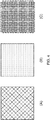
- FIGs 4a-c are schematic representations of separation elements or linings for a cooling system according to an example.
- a mesh is provided in the form of an encapsulated metallic structure, similar to, for example, metal fencing.
- the orientation and size of the openings may be selected for the environment in which the mesh is to be deployed. For example, if the mesh is to be used only to prevent bulk movement of doped material, it may be that the openings are of the order of several centimetres in diameter. On the other hand, if the mesh is to be used to prevent subterranean animals from passing or burrowing through into the doped region, the openings may be made an order of magnitude smaller for example. Other alternatives are possible as will be appreciated by those skilled in the art.
- a lining is provided in the form of a laminar element with holes in.
- the size and positioning of the holes can be selected as desired.
- a lining is provided in the form a weaved material made from, for example, nylon. The gaps between the warp and weft of the material can enable ingress or egress of moisture but prevent migration of doped material and ingress of animals and so on.
- the lining can be flexible in order to enable it to be placed into a hole into which apparatus is to be deployed, and cut to size.
Landscapes
- Engineering & Computer Science (AREA)
- Physics & Mathematics (AREA)
- Microelectronics & Electronic Packaging (AREA)
- Thermal Sciences (AREA)
- Environmental & Geological Engineering (AREA)
- Optics & Photonics (AREA)
- General Physics & Mathematics (AREA)
- Life Sciences & Earth Sciences (AREA)
- General Life Sciences & Earth Sciences (AREA)
- Mining & Mineral Resources (AREA)
- Paleontology (AREA)
- Civil Engineering (AREA)
- General Engineering & Computer Science (AREA)
- Structural Engineering (AREA)
- Road Paving Structures (AREA)
Priority Applications (1)
| Application Number | Priority Date | Filing Date | Title |
|---|---|---|---|
| EP15305372.3A EP3067471A1 (de) | 2015-03-12 | 2015-03-12 | Verfahren zur modifizierung thermischer leistung und kühlsystem |
Applications Claiming Priority (1)
| Application Number | Priority Date | Filing Date | Title |
|---|---|---|---|
| EP15305372.3A EP3067471A1 (de) | 2015-03-12 | 2015-03-12 | Verfahren zur modifizierung thermischer leistung und kühlsystem |
Publications (1)
| Publication Number | Publication Date |
|---|---|
| EP3067471A1 true EP3067471A1 (de) | 2016-09-14 |
Family
ID=52811080
Family Applications (1)
| Application Number | Title | Priority Date | Filing Date |
|---|---|---|---|
| EP15305372.3A Withdrawn EP3067471A1 (de) | 2015-03-12 | 2015-03-12 | Verfahren zur modifizierung thermischer leistung und kühlsystem |
Country Status (1)
| Country | Link |
|---|---|
| EP (1) | EP3067471A1 (de) |
Cited By (4)
| Publication number | Priority date | Publication date | Assignee | Title |
|---|---|---|---|---|
| WO2018187270A1 (en) | 2017-04-07 | 2018-10-11 | Bobsbox, Llc. | In-ground enclosure system |
| US10903635B2 (en) | 2017-04-07 | 2021-01-26 | BOBsBOX, LLC | In-ground enclosure system |
| WO2021072189A1 (en) | 2019-10-11 | 2021-04-15 | BOBsBOX, LLC | In-ground enclosure system |
| CN112739103A (zh) * | 2020-12-25 | 2021-04-30 | 重庆星科裕信息科技有限公司 | 一种基于5g网络的智能井盖 |
Citations (4)
| Publication number | Priority date | Publication date | Assignee | Title |
|---|---|---|---|---|
| JPS61275383A (ja) * | 1985-05-29 | 1986-12-05 | Mitsui Constr Co Ltd | 土壌の熱伝導率改良法 |
| WO2003056892A1 (es) * | 2002-01-04 | 2003-07-10 | Metalurgica Casbar, S.A. | Metodo para disipacion del calor generado en armarios contenedores de equipos electronicos, en redes subterraneas de telecomunicacion |
| US20070062670A1 (en) * | 2003-11-19 | 2007-03-22 | Tyco Electrnics Raychem Nv | Casing with cooling means |
| WO2010065182A1 (en) * | 2008-12-04 | 2010-06-10 | 3M Innovative Properties Company | Underground battery compartment |
-
2015
- 2015-03-12 EP EP15305372.3A patent/EP3067471A1/de not_active Withdrawn
Patent Citations (4)
| Publication number | Priority date | Publication date | Assignee | Title |
|---|---|---|---|---|
| JPS61275383A (ja) * | 1985-05-29 | 1986-12-05 | Mitsui Constr Co Ltd | 土壌の熱伝導率改良法 |
| WO2003056892A1 (es) * | 2002-01-04 | 2003-07-10 | Metalurgica Casbar, S.A. | Metodo para disipacion del calor generado en armarios contenedores de equipos electronicos, en redes subterraneas de telecomunicacion |
| US20070062670A1 (en) * | 2003-11-19 | 2007-03-22 | Tyco Electrnics Raychem Nv | Casing with cooling means |
| WO2010065182A1 (en) * | 2008-12-04 | 2010-06-10 | 3M Innovative Properties Company | Underground battery compartment |
Cited By (8)
| Publication number | Priority date | Publication date | Assignee | Title |
|---|---|---|---|---|
| WO2018187270A1 (en) | 2017-04-07 | 2018-10-11 | Bobsbox, Llc. | In-ground enclosure system |
| KR20200009002A (ko) * | 2017-04-07 | 2020-01-29 | 밥스박스, 엘엘씨. | 지면 매설형 인클로저 시스템 |
| EP3607676A4 (de) * | 2017-04-07 | 2020-12-09 | Bobsbox, LLC. | Bodengehäusesystem |
| US10903635B2 (en) | 2017-04-07 | 2021-01-26 | BOBsBOX, LLC | In-ground enclosure system |
| EP4235988A3 (de) * | 2017-04-07 | 2023-10-18 | Bobsbox, LLC. | Bodengehäusesystem |
| WO2021072189A1 (en) | 2019-10-11 | 2021-04-15 | BOBsBOX, LLC | In-ground enclosure system |
| EP4042531A4 (de) * | 2019-10-11 | 2023-11-08 | Bobsbox, Llc | Bodengehäusesystem |
| CN112739103A (zh) * | 2020-12-25 | 2021-04-30 | 重庆星科裕信息科技有限公司 | 一种基于5g网络的智能井盖 |
Similar Documents
| Publication | Publication Date | Title |
|---|---|---|
| EP3067471A1 (de) | Verfahren zur modifizierung thermischer leistung und kühlsystem | |
| CN110232990B (zh) | 挤压型中压直流电缆 | |
| US7670033B2 (en) | Fire stop for light fixture | |
| CN101711416B (zh) | 具有整体式支撑的铠装线缆 | |
| CN113595011B (zh) | 一种带有自除雪功能的电力电缆 | |
| KR101552162B1 (ko) | 도로 결빙 방지 시스템 | |
| KR102230585B1 (ko) | 종단접속함 | |
| US20180190409A1 (en) | Electric Power Cable And A Process For The Production Of The Power Cable | |
| JP2017508429A (ja) | 材料並びに関連配置、システム、及び方法 | |
| US7045716B2 (en) | Electrical cable | |
| Hanna et al. | Thermal analysis of power cables in multi-layered soil. II. Practical considerations | |
| US20020044836A1 (en) | Composition having low thermal resistivity and method for laying underground cables for carrying electrical energy | |
| Zsembinszki et al. | Analysis of implementing phase change materials in open-air swimming pools | |
| KR20150029195A (ko) | 침수방지 맨홀 구조체 | |
| CN111816362B (zh) | 一种气转移式抗冻耐高温电缆 | |
| CN208904237U (zh) | 一种变电站接地网 | |
| US20100166412A1 (en) | Rapid deployment surveillance system | |
| EP3068203A1 (de) | Kühlsystem, verfahren zur kühlung und elektronische vorrichtung | |
| TW527461B (en) | Electrothermic membrane with metal core for waterproofing and protecting structures | |
| CN202524693U (zh) | 电子设备密封结构及电子电源 | |
| CN118507138A (zh) | 一种防鼠蚁阻燃耐火阻水电力电缆 | |
| CN110010278B (zh) | 一种地埋式自驱虫电缆及其埋设方法 | |
| ES2734986T3 (es) | Procedimiento de protección de un cable y cubierta de protección del cable | |
| WO1999064367A1 (en) | Composition having low thermal resistivity and method for laying underground cables for carrying electrical energy | |
| KR101308672B1 (ko) | 온도제어가 가능한 배터리 케이스 |
Legal Events
| Date | Code | Title | Description |
|---|---|---|---|
| PUAI | Public reference made under article 153(3) epc to a published international application that has entered the european phase |
Free format text: ORIGINAL CODE: 0009012 |
|
| AK | Designated contracting states |
Kind code of ref document: A1 Designated state(s): AL AT BE BG CH CY CZ DE DK EE ES FI FR GB GR HR HU IE IS IT LI LT LU LV MC MK MT NL NO PL PT RO RS SE SI SK SM TR |
|
| AX | Request for extension of the european patent |
Extension state: BA ME |
|
| STAA | Information on the status of an ep patent application or granted ep patent |
Free format text: STATUS: THE APPLICATION HAS BEEN PUBLISHED |
|
| STAA | Information on the status of an ep patent application or granted ep patent |
Free format text: STATUS: THE APPLICATION IS DEEMED TO BE WITHDRAWN |
|
| 18D | Application deemed to be withdrawn |
Effective date: 20170315 |