EP3067519A1 - Pale de ventilateur pour une propulsion aeronautique - Google Patents
Pale de ventilateur pour une propulsion aeronautique Download PDFInfo
- Publication number
- EP3067519A1 EP3067519A1 EP16155260.9A EP16155260A EP3067519A1 EP 3067519 A1 EP3067519 A1 EP 3067519A1 EP 16155260 A EP16155260 A EP 16155260A EP 3067519 A1 EP3067519 A1 EP 3067519A1
- Authority
- EP
- European Patent Office
- Prior art keywords
- blade
- elastomer layer
- fan blade
- fan
- suction side
- Prior art date
- Legal status (The legal status is an assumption and is not a legal conclusion. Google has not performed a legal analysis and makes no representation as to the accuracy of the status listed.)
- Granted
Links
Images



Classifications
-
- F—MECHANICAL ENGINEERING; LIGHTING; HEATING; WEAPONS; BLASTING
- F01—MACHINES OR ENGINES IN GENERAL; ENGINE PLANTS IN GENERAL; STEAM ENGINES
- F01D—NON-POSITIVE DISPLACEMENT MACHINES OR ENGINES, e.g. STEAM TURBINES
- F01D5/00—Blades; Blade-carrying members; Heating, heat-insulating, cooling or antivibration means on the blades or the members
- F01D5/12—Blades
- F01D5/28—Selecting particular materials; Particular measures relating thereto; Measures against erosion or corrosion
-
- F—MECHANICAL ENGINEERING; LIGHTING; HEATING; WEAPONS; BLASTING
- F01—MACHINES OR ENGINES IN GENERAL; ENGINE PLANTS IN GENERAL; STEAM ENGINES
- F01D—NON-POSITIVE DISPLACEMENT MACHINES OR ENGINES, e.g. STEAM TURBINES
- F01D5/00—Blades; Blade-carrying members; Heating, heat-insulating, cooling or antivibration means on the blades or the members
- F01D5/12—Blades
- F01D5/14—Form or construction
- F01D5/16—Form or construction for counteracting blade vibration
-
- F—MECHANICAL ENGINEERING; LIGHTING; HEATING; WEAPONS; BLASTING
- F01—MACHINES OR ENGINES IN GENERAL; ENGINE PLANTS IN GENERAL; STEAM ENGINES
- F01D—NON-POSITIVE DISPLACEMENT MACHINES OR ENGINES, e.g. STEAM TURBINES
- F01D5/00—Blades; Blade-carrying members; Heating, heat-insulating, cooling or antivibration means on the blades or the members
- F01D5/12—Blades
- F01D5/28—Selecting particular materials; Particular measures relating thereto; Measures against erosion or corrosion
- F01D5/282—Selecting composite materials, e.g. blades with reinforcing filaments
-
- F—MECHANICAL ENGINEERING; LIGHTING; HEATING; WEAPONS; BLASTING
- F01—MACHINES OR ENGINES IN GENERAL; ENGINE PLANTS IN GENERAL; STEAM ENGINES
- F01D—NON-POSITIVE DISPLACEMENT MACHINES OR ENGINES, e.g. STEAM TURBINES
- F01D5/00—Blades; Blade-carrying members; Heating, heat-insulating, cooling or antivibration means on the blades or the members
- F01D5/34—Rotor-blade aggregates of unitary construction, e.g. formed of sheet laminae
-
- F—MECHANICAL ENGINEERING; LIGHTING; HEATING; WEAPONS; BLASTING
- F04—POSITIVE - DISPLACEMENT MACHINES FOR LIQUIDS; PUMPS FOR LIQUIDS OR ELASTIC FLUIDS
- F04D—NON-POSITIVE-DISPLACEMENT PUMPS
- F04D29/00—Details, component parts, or accessories
- F04D29/02—Selection of particular materials
- F04D29/023—Selection of particular materials especially adapted for elastic fluid pumps
-
- F—MECHANICAL ENGINEERING; LIGHTING; HEATING; WEAPONS; BLASTING
- F04—POSITIVE - DISPLACEMENT MACHINES FOR LIQUIDS; PUMPS FOR LIQUIDS OR ELASTIC FLUIDS
- F04D—NON-POSITIVE-DISPLACEMENT PUMPS
- F04D29/00—Details, component parts, or accessories
- F04D29/26—Rotors specially for elastic fluids
- F04D29/32—Rotors specially for elastic fluids for axial flow pumps
- F04D29/321—Rotors specially for elastic fluids for axial flow pumps for axial flow compressors
- F04D29/324—Blades
-
- F—MECHANICAL ENGINEERING; LIGHTING; HEATING; WEAPONS; BLASTING
- F04—POSITIVE - DISPLACEMENT MACHINES FOR LIQUIDS; PUMPS FOR LIQUIDS OR ELASTIC FLUIDS
- F04D—NON-POSITIVE-DISPLACEMENT PUMPS
- F04D29/00—Details, component parts, or accessories
- F04D29/26—Rotors specially for elastic fluids
- F04D29/32—Rotors specially for elastic fluids for axial flow pumps
- F04D29/325—Rotors specially for elastic fluids for axial flow pumps for axial flow fans
-
- F—MECHANICAL ENGINEERING; LIGHTING; HEATING; WEAPONS; BLASTING
- F04—POSITIVE - DISPLACEMENT MACHINES FOR LIQUIDS; PUMPS FOR LIQUIDS OR ELASTIC FLUIDS
- F04D—NON-POSITIVE-DISPLACEMENT PUMPS
- F04D29/00—Details, component parts, or accessories
- F04D29/26—Rotors specially for elastic fluids
- F04D29/32—Rotors specially for elastic fluids for axial flow pumps
- F04D29/38—Blades
- F04D29/388—Blades characterised by construction
-
- F—MECHANICAL ENGINEERING; LIGHTING; HEATING; WEAPONS; BLASTING
- F04—POSITIVE - DISPLACEMENT MACHINES FOR LIQUIDS; PUMPS FOR LIQUIDS OR ELASTIC FLUIDS
- F04D—NON-POSITIVE-DISPLACEMENT PUMPS
- F04D29/00—Details, component parts, or accessories
- F04D29/66—Combating cavitation, whirls, noise, vibration or the like; Balancing
- F04D29/661—Combating cavitation, whirls, noise, vibration or the like; Balancing especially adapted for elastic fluid pumps
- F04D29/668—Combating cavitation, whirls, noise, vibration or the like; Balancing especially adapted for elastic fluid pumps damping or preventing mechanical vibrations
-
- F—MECHANICAL ENGINEERING; LIGHTING; HEATING; WEAPONS; BLASTING
- F05—INDEXING SCHEMES RELATING TO ENGINES OR PUMPS IN VARIOUS SUBCLASSES OF CLASSES F01-F04
- F05D—INDEXING SCHEME FOR ASPECTS RELATING TO NON-POSITIVE-DISPLACEMENT MACHINES OR ENGINES, GAS-TURBINES OR JET-PROPULSION PLANTS
- F05D2220/00—Application
- F05D2220/30—Application in turbines
- F05D2220/36—Application in turbines specially adapted for the fan of turbofan engines
-
- F—MECHANICAL ENGINEERING; LIGHTING; HEATING; WEAPONS; BLASTING
- F05—INDEXING SCHEMES RELATING TO ENGINES OR PUMPS IN VARIOUS SUBCLASSES OF CLASSES F01-F04
- F05D—INDEXING SCHEME FOR ASPECTS RELATING TO NON-POSITIVE-DISPLACEMENT MACHINES OR ENGINES, GAS-TURBINES OR JET-PROPULSION PLANTS
- F05D2230/00—Manufacture
- F05D2230/20—Manufacture essentially without removing material
-
- F—MECHANICAL ENGINEERING; LIGHTING; HEATING; WEAPONS; BLASTING
- F05—INDEXING SCHEMES RELATING TO ENGINES OR PUMPS IN VARIOUS SUBCLASSES OF CLASSES F01-F04
- F05D—INDEXING SCHEME FOR ASPECTS RELATING TO NON-POSITIVE-DISPLACEMENT MACHINES OR ENGINES, GAS-TURBINES OR JET-PROPULSION PLANTS
- F05D2230/00—Manufacture
- F05D2230/20—Manufacture essentially without removing material
- F05D2230/25—Manufacture essentially without removing material by forging
-
- F—MECHANICAL ENGINEERING; LIGHTING; HEATING; WEAPONS; BLASTING
- F05—INDEXING SCHEMES RELATING TO ENGINES OR PUMPS IN VARIOUS SUBCLASSES OF CLASSES F01-F04
- F05D—INDEXING SCHEME FOR ASPECTS RELATING TO NON-POSITIVE-DISPLACEMENT MACHINES OR ENGINES, GAS-TURBINES OR JET-PROPULSION PLANTS
- F05D2230/00—Manufacture
- F05D2230/90—Coating; Surface treatment
-
- F—MECHANICAL ENGINEERING; LIGHTING; HEATING; WEAPONS; BLASTING
- F05—INDEXING SCHEMES RELATING TO ENGINES OR PUMPS IN VARIOUS SUBCLASSES OF CLASSES F01-F04
- F05D—INDEXING SCHEME FOR ASPECTS RELATING TO NON-POSITIVE-DISPLACEMENT MACHINES OR ENGINES, GAS-TURBINES OR JET-PROPULSION PLANTS
- F05D2240/00—Components
- F05D2240/20—Rotors
- F05D2240/30—Characteristics of rotor blades, i.e. of any element transforming dynamic fluid energy to or from rotational energy and being attached to a rotor
- F05D2240/306—Characteristics of rotor blades, i.e. of any element transforming dynamic fluid energy to or from rotational energy and being attached to a rotor related to the suction side of a rotor blade
-
- F—MECHANICAL ENGINEERING; LIGHTING; HEATING; WEAPONS; BLASTING
- F05—INDEXING SCHEMES RELATING TO ENGINES OR PUMPS IN VARIOUS SUBCLASSES OF CLASSES F01-F04
- F05D—INDEXING SCHEME FOR ASPECTS RELATING TO NON-POSITIVE-DISPLACEMENT MACHINES OR ENGINES, GAS-TURBINES OR JET-PROPULSION PLANTS
- F05D2300/00—Materials; Properties thereof
- F05D2300/40—Organic materials
- F05D2300/43—Synthetic polymers, e.g. plastics; Rubber
-
- F—MECHANICAL ENGINEERING; LIGHTING; HEATING; WEAPONS; BLASTING
- F05—INDEXING SCHEMES RELATING TO ENGINES OR PUMPS IN VARIOUS SUBCLASSES OF CLASSES F01-F04
- F05D—INDEXING SCHEME FOR ASPECTS RELATING TO NON-POSITIVE-DISPLACEMENT MACHINES OR ENGINES, GAS-TURBINES OR JET-PROPULSION PLANTS
- F05D2300/00—Materials; Properties thereof
- F05D2300/50—Intrinsic material properties or characteristics
- F05D2300/501—Elasticity
-
- F—MECHANICAL ENGINEERING; LIGHTING; HEATING; WEAPONS; BLASTING
- F05—INDEXING SCHEMES RELATING TO ENGINES OR PUMPS IN VARIOUS SUBCLASSES OF CLASSES F01-F04
- F05D—INDEXING SCHEME FOR ASPECTS RELATING TO NON-POSITIVE-DISPLACEMENT MACHINES OR ENGINES, GAS-TURBINES OR JET-PROPULSION PLANTS
- F05D2300/00—Materials; Properties thereof
- F05D2300/50—Intrinsic material properties or characteristics
- F05D2300/522—Density
-
- F—MECHANICAL ENGINEERING; LIGHTING; HEATING; WEAPONS; BLASTING
- F05—INDEXING SCHEMES RELATING TO ENGINES OR PUMPS IN VARIOUS SUBCLASSES OF CLASSES F01-F04
- F05D—INDEXING SCHEME FOR ASPECTS RELATING TO NON-POSITIVE-DISPLACEMENT MACHINES OR ENGINES, GAS-TURBINES OR JET-PROPULSION PLANTS
- F05D2300/00—Materials; Properties thereof
- F05D2300/60—Properties or characteristics given to material by treatment or manufacturing
- F05D2300/615—Filler
-
- Y—GENERAL TAGGING OF NEW TECHNOLOGICAL DEVELOPMENTS; GENERAL TAGGING OF CROSS-SECTIONAL TECHNOLOGIES SPANNING OVER SEVERAL SECTIONS OF THE IPC; TECHNICAL SUBJECTS COVERED BY FORMER USPC CROSS-REFERENCE ART COLLECTIONS [XRACs] AND DIGESTS
- Y02—TECHNOLOGIES OR APPLICATIONS FOR MITIGATION OR ADAPTATION AGAINST CLIMATE CHANGE
- Y02T—CLIMATE CHANGE MITIGATION TECHNOLOGIES RELATED TO TRANSPORTATION
- Y02T50/00—Aeronautics or air transport
- Y02T50/60—Efficient propulsion technologies, e.g. for aircraft
Definitions
- the invention relates to a fan blade for a flight drive according to the preamble of claim 1.
- Aero engines must be able to withstand a fan blade loss.
- a fan blade loss occurs when a fan blade breaks and blade segments separate, which can cause significant damage to the engine and the entire aircraft.
- the proportionately radially outward mass of the lost fan blade causes high impact forces in the fan case.
- a relatively heavy fan housing, a strong front bearing structure and a relatively heavy fan rotor are required. These cause high imbalance forces introduced into the aircraft-side engine mount, which in turn leads to the requirement to make the engine mount relatively heavy and massive.
- honeycomb fills according to the US 2014/0072427 A1 are introduced into suction recesses of fan blades, unsuitable for damping against blade vibrations and prone to cracking during overstretching, for example in the case of a bird strike.
- the main body of the fan blade introduced grooves corresponding to US 5,913,661 A
- the solution according to the invention is characterized in that the fan blade has a large-area elastomer layer which forms at least 20% of the surface of the suction side of the fan blade and whose thickness increases in the radial direction outwardly at least in sections.
- the elastomer layer is formed in one piece and contiguous from a full elastomer and not provided with cavities.
- the at least partial formation of the suction side of the blade by an elastomer layer has the advantage that the weight of the fan blade is reduced by the elastomer layer due to its comparatively low density, which leads to a reduction of the impact load and the balancing load in the event of fan blade loss.
- a reduction of the impact load and the Umwuchtlast in the case of a fan blade loss of up to 30% can be achieved by the inventive solution.
- a further advantage in the use of a large-area elastomer layer is that the elastomer layer applied over a large area to the fan blade serves as a vibration damper against blade vibrations, which are excited, for example, by engine vibrations and their frequency multiples.
- the vibration damping property is related to the elastomeric layer having a lower modulus of elasticity than the other blade material (typically a metal or metal alloy), so that other vibration characteristics are provided.
- a third advantage of the inventive arrangement of an elastomer on the suction side of the fan blade is that the separate application of a metal lid on the elastomer layer and thus the risk of cracking on the connection of such a metal lid with the Fanschaufel groundSystem in case of overstretching (for example Bird strike) can be avoided. It is provided that the elastomer is resistant to wear and accordingly suitable to form the suction side of the fan blade.
- the elastomer layer covers a proportion of 20% to 80%, in particular a proportion of 30% to 50% of the area of the suction side of the blade.
- the large-area elastomer layer forms a massive, homogeneous structure of an elastomer.
- the elastomer layer is not formed by separate items, but represents a single, coherent structure.
- the surface of the suction side of the blade to which the proportion of at least 20% refers becomes that area on the suction side of the blade viewed at the intended use of the blade in a fan gas or air flows past.
- the elastomer layer is spaced from the leading edge and / or spaced from the trailing edge formed on the suction side of the blade.
- there is a spacing to the leading edge as it must withstand a particular extent bombardment with particles or objects possibly located in the gas stream and is accordingly advantageously formed from a metal.
- a further embodiment of the invention provides that the elastomer layer is formed predominantly in the region of the blade on the suction side, which, relative to the total height of the blade, constitutes the radially outer half of the blade.
- the elastomer layer is thus provided predominantly in the radially outer region of the blade. This is of particular advantage since this reduces the weight of the fan blade in the radially outer region, which leads to a reduction of the impact load and the balancing load in the event of a fan blade loss.
- hybrid fan blades according to the invention in engines which hitherto use all-metal fan blades and in which the relatively high thickness of the outer portion of the fan blade is necessary to achieve a good aerodynamic profile, but does not contribute to the same extent to the strength of the all-metal fan blade ,
- Here can be saved by attaching a large-area elastomer layer on the suction side of the blade in particular weight. It has been found that the full thickness of the fan blade at the radially outer end for the blade strength is not needed and the all-metallic blade material can be substantially replaced by the elastomer layer according to the invention.
- the elastomer layer extends to the blade tip of the blade. Because the elastomer layer expands more radially under centrifugal force due to their lower modulus of elasticity, for example, about 20 to 30 N / mm 2 in comparison to titanium with a modulus of elasticity of 105,000 N / mm 2, the elastomer layer on the Fanschaufelspitze against the metal is Body radially shortened. This avoids that the elastomer layer starts radially under centrifugal expansion at the fan housing and is thereby damaged. Alternatively, the elastomer layer terminates at a distance from the blade tip, the for example, in the range between 0.5 mm and 5 cm. As a result, it can be prevented, for example, that the elastomer layer expands beyond the blade tip during operation due to the centrifugal force.
- the elastomer layer is formed on the suction side substantially U-shaped, wherein the open end of the U-shaped portion terminates at the blade tip or facing it. According to this embodiment, the elastomer layer thus begins on the suction side in a central region and widens with increasing radial height to the blade tip or to just before the blade tip.
- the elastomer layer in the region of the blade in which it is arranged has a proportion of the total thickness of the blade of up to 50%, up to 60%, up to 70% or up to 80%. having.
- the elastomer layer in the area of the blade in which the elastomer layer is provided, it can make up a substantial portion of the thickness of the blade, up to 80%.
- the thickness of the elastomer layer preferably increases continuously from radially inward to radially outward.
- the thickness of the elastomer layer increases at least in sections in the radial direction to the outside.
- the thickness of the elastomer layer thus increases either continuously with increasing radial height of the blade or, after it has reached a certain thickness, remains constant in its thickness.
- a large-area stiffness transition in the radial direction is provided which takes place continuously and steadily and does not involve any jumps in rigidity, as would occur, for example, in the case of axially extending ribs.
- the bucket becomes softer towards the outside. This improves the property of the elastomer layer to counteract blade vibration as a vibration damper.
- the thickness of the elastomeric layer which increases outward at least in sections, can be accompanied by a thickness of a metal main body of the fan blade which is outwardly at least partially or constantly decreasing, to which the elastomer layer is applied is.
- the proportion of metal on the fan blade decreases and the weight of the fan blade is increasingly reduced to a radially outer portion of the fan blade.
- the fan blade is formed according to an advantageous embodiment of the invention, apart from the elastomer layer as a one-piece, all-metal blade.
- the blade consists in this case of a blade body made of metal and the elastomer layer, which forms the surface of the suction side of the blade over a large area.
- the blade base body consists of a forged metal.
- the invention is by no means limited to the fact that the fan blade is formed in its main blade body as a forged blade.
- other manufacturing methods such as e.g. Metal powder injection molding and milling are used.
- the blade body does not necessarily have to be formed in one piece and solid.
- the blade base body is designed as a composite blade on the basis of carbon fibers.
- the weight of such Kompositfanschaufel can be reduced in the outer region by a suction side applied elastomer layer to reduce stresses in the blade root.
- a reduction of fan blade vibrations can be achieved by a blade damping means of the elastomer layer.
- a further embodiment of the invention provides that the blade material in the region which does not form the elastomer layer has a large-area recess. In the absence of the elastomer layer, this large-area recess is formed toward the suction side of the blade. The elastomer layer is applied to this large-area recess and completes in this way the fan blade.
- Such a large-area recess can be incorporated in the fan blade, for example, when forging the blade body.
- the introduction of the recess is carried out by milling or other machining methods after production of the blade body. After the elastomer layer is applied to the large-area recess, it can be provided that they is then milled to provide exactly the aerodynamically desired shape of the suction side.
- the elastomeric layer can be provided, for example, as an injection-molded part or by vulcanizing a prefabricated pad.
- the connection of the elastomer layer to the blade body follows, for example, by gluing.
- certain surface roughnesses of the blade main body are provided in the region of the recess and / or the elastomer layer.
- positive-locking connections can also be provided.
- the elastomeric layer may in principle be made of any elastomer, i. made of any dimensionally stable, elastically deformable plastic.
- the elastomer layer is formed, for example, from a fluorinated hydrocarbon, for example from fluororubber, especially copolymer, wherein the elastomer layer is applied according to an embodiment directly on the metallic body of the fan blade and crosslinked there, preferably crosslinked peroxide.
- Copolymer is characterized by its low-temperature flexibility and dimensional stability under pressure. Its low-temperature flexibility makes it well suited for cold ambient temperatures, for example in winter and at high altitudes. Furthermore, it gives the hybrid fan blade good resistance to major elastic deformations, especially bird strikes.
- the high dimensional stability under pressure load gives the hybrid fan blade a high dimensional stability of the aerodynamic profile and thus a high efficiency.
- the fan blade can be applied by injection molding or by vulcanizing prefabricated pads by means of gluing or vulcanization on the whole metal body.
- the crosslinking, vulcanization or bonding of prefabricated pads is done in one embodiment under pressure to achieve a better connection to the blade body.
- This can be achieved by one or more flexible or rigid moldings, by means of which or a prefabricated pad during crosslinking, vulcanizing or gluing with a sufficiently high pressure, for example in the range of 50 kPa to 1000 kPa, in particular in the range of 100 kPa to 200 kPa is pressed onto the blade body.
- the elastomer layer has a lower density than the blade main body. This applies both in the case that the blade body is massively formed of metal (for example made of titanium with a density of 4.50 g / cm 3 ), as well as for the case that the blade body is made in composite construction, in which case the Density typically is about 1.90 to 2.00 g / cm 3 .
- the density of the elastomer is at least a factor of 2 or at least a factor of 4 lower than the density of the blade body.
- the choice of material can be made such that the elastomer layer on its outer side (which forms the suction side of the fan blade) has a high abrasive wear resistance. This is achieved, for example, by the choice of an elastomer having a Shore A hardness of at least 50, in particular of at least 60, e.g. of at least 80.
- the invention further relates to a fan for a turbofan engine with a plurality of blades according to claim 1.
- Fan blades according to the present invention also include propeller blades.
- the FIG. 7 schematically shows a turbofan engine 1.
- the turbofan engine 1 includes a low pressure compressor 10 with a fan 11, a medium pressure compressor 20, a high pressure compressor 30, a combustion chamber 40, a high pressure turbine 50, a medium pressure turbine 60 and a low pressure turbine 70.
- the medium pressure compressor 20 and the high pressure compressor 30 have each have a plurality of compressor stages, each compressor stage comprising a rotor and a stator.
- the turbofan engine 1 comprises a low-pressure compressor, which is arranged in the core engine in front of the high-pressure compressor 30.
- the low-pressure compressor 10 comprises a fan 11 with fan blades 12, which are fastened to a fan disk 13.
- the low-pressure compressor 10 further includes a fan case 15.
- the turbofan engine forms a secondary flow channel or bypass channel 4 and a primary flow channel 3, which leads through the core engine. Air is sucked and accelerated by the fan 11, wherein two air streams are provided, a first air flow through the primary flow channel 3 and a second air flow through the secondary flow channel 4. In the secondary flow channel 4 while vanes 45 and / or struts can be arranged.
- the high-pressure turbine 50, the medium-pressure turbine 60 and the low-pressure turbine 70 respectively drive the high-pressure compressor 30, the medium-pressure compressor 20 and the fan 11 via a high-pressure shaft, a medium-pressure shaft and a low-pressure shaft.
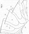
- FIG. 1 is a perspective view obliquely from the front of a plurality of fan blades 12 of a fan.
- Each fan blade 12 comprises a front edge 121, a trailing edge 122, a blade tip 123, a suction side 124 and a pressure side 125.
- a separate blade root is due to the BLISK design in the embodiment of FIG. 1 not provided. As for the FIG. 2 will be explained, however, the individual fan blades 12 may also be formed with a blade root.
- the fan blade 12 further comprises an elastomer layer 14 which is formed over a large area on the suction side 124 of the blade 12.
- a large-area arrangement of the elastomer layer 14 on the suction side of the blade 12 means that the elastomer layer occupies at least 20% of the area of the suction side 124 of the blade 12. Preferably, this percentage is greater and is for example in the range between 20% and 80%, in particular in the range between 30% and 50% of the area of the suction side of the blade 12.
- the elastomer layer 14 is, for example, a fluorinated hydrocarbon, in particular a fluororubber, which is distinguished by a high abrasive wear resistance and is therefore suitable for forming the suction side of the blade 12.
- the elastomer layer 14 is vulcanized onto the blade base material, for example, as described with reference to FIGS FIG. 3 will be explained.
- FIG. 2 shows an alternative embodiment of a fan blade 12.
- the fan blade 12 is intended for use with a plug fan.
- the fan blade 12 of the FIG. 2 a blade root 126, which can be plugged into a corresponding disc or other structure of the fan in a conventional manner.
- the connection of the fan blade 12 with the fan disk 13 does not matter in the context of the present invention.
- the Fan blade 12 also has an elastomer layer 14 which is arranged on the suction side 124 of the blade 12.
- the shape of the elastomer layer 14 will be described with reference to FIGS FIG. 2 explained in more detail. The explanations apply equally to the FIG. 1 in which the elastomeric layer 14 is partially obscured by other fan blades.
- the elastomeric layer 14 has a shape such that it is spaced from the leading edge 121 of the fan blade 12. Furthermore, the elastomer layer 14 is also spaced from the trailing edge 122 of the fan blade.
- the elastomer layer 14 forms a U-shaped region. It is accordingly bounded by a bent region 143, to which two legs 141, 142 adjoin in the radial direction, which delimit the elastomer layer 14 in the axial direction forwards and backwards.
- the elastomer layer 14 widens in the radial direction from a small axial extent in the bent region 143 to an increasing axial extent towards the blade edge 123.
- the blade 12 is formed in the regions which are not formed by the elastomer layer 14, by a blade body.
- This may be a one-piece, forged full metal, such as titanium.
- the blade base body can also be designed in composite construction, for example as a composite fan blade based on carbon fibers.
- the blade main body has a large-area recess or flattening. This is in the presentation of FIG. 3 which shows a view from the direction of the blade tip 123. Thereafter, a large-area recess 128 is introduced in the blade main body 127 to the suction side 124. This recess 128 can be incorporated, for example, in the forging of the blade body 127 in this. According to an alternative embodiment, the recess 128 is subsequently milled into the blade material, ground or introduced in any other way.
- the elastomer layer 14 is, for example, directly crosslinked as an injection molding compound on the all-metal body 127 in the injection mold or produced as a separate injection molded part and then glued into the recess 128.
- the elastomer layer 14 is provided by a prefabricated pad, which is vulcanized onto the recess 14. After attaching or securing the elastomer layer 14 in the recess 128 may be provided that the elastomer layer 14 is milled or ground to give her exactly the desired shape on the suction side of the blade 12.
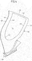
- FIG. 4 shows a modification of the blade of the FIG. 2
- the embodiment of FIG. 4 differs from the embodiment of FIG. 2 in that the elastomeric layer 14 does not extend to the blade tip 123, but an edge 129 remains between the blade tip 123 and the open end of the U-shaped elastomer layer 14.
- the width of the edge 129 may be, for example, between 5 mm and 5 cm.
- the thickness of the elastomer layer 14 varies in the radial direction and / or in the axial direction. This applies to all embodiments of the FIGS. 1 to 4 .
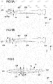
- the FIGS. 5A and 5B show the variation of the thickness d1 of the elastomer layer 14 in the longitudinal direction of the blade, ie in the radial direction r.
- the FIG. 5A shows an example of a longitudinal section through the blade of the Figures 1-3 and the FIG. 5B shows an example of a longitudinal section through the blade of FIG. 4 , Accordingly, extends in the FIG. 5A the elastomer layer 14 to the blade edge 123. In the FIG. 5B the edge 129 remains between the elastomer layer 14 and the blade edge 123.
- the thickness d1 of the elastomer layer 14 increases from a radially inward point (in the bent region 143) towards the blade tip 123, this being accompanied by a thickness d2 of the metallic base body 127 which constantly decreases toward the outside. This ensures that with increasing radius r the proportion of metal on the blade decreases and, accordingly, the weight of the blade is increasingly reduced to the radially outer portion of the blade.
- the continuous increase in the thickness d1 of the elastomer layer 14 towards the blade tip 123 causes a large-area transition of the rigidity of the blade in the radial direction r.
- the thickness d2 of the metallic blade main body 127 remaining adjacent to the blade tip 123 is sufficient to provide the necessary blade stability.
- the elastomer layer 14 tapers again in its radially outermost end region over the radial distance k, ie over the distance k it has a thickness d1 which decreases toward the blade edge 123, without the thickness d2 of the blade base body 127 increasing thereby. It is insofar an edge shortening of the elastomer layer 14 before. But this is only optional.
- FIG. 5B remains an edge 129 between the elastomer layer 14 and the blade edge 123. Also in the FIG. 5B reduces the thickness d1 of the elastomer layer 14 in its radially outermost end region, here with increasing thickness d2 of the blade body 127. Again, this is only optional.
- the thickness d1 of the elastomer layer 14 increases towards the blade tip 123 up to 80% of the total thickness of the blade 12.
- the thickness of the elastomer layer 14 at the radially outer end of the elastomer layer may be up to 4mm.
- FIG. 6 schematically shows a thickness distribution, showing a cross section through a blade 12, ie a section in the axial direction x and in the circumferential direction u and thereby perpendicular to the radial direction.
- the thickness d1 of the elastomer layer 14 decreases towards the leading edge 121 and the trailing edge 122.
- the thickness d1 of the elastomer layer is greatest and the thickness d2 of the blade main body 127 is only about 50% to 20%, preferably 20%, of the total thickness d3 of the blade 12.
- the dashed lines of the FIG. 6 indicate the thickness d1 of the elastomeric layer 14 for cuts at other radial heights. According to the FIG. 5 increases the thickness of the elastomer layer 14 with the radial blade extension. The FIG. 6 Thus, the solid line indicates the thickness of the elastomer layer 14 near the blade tip 123.
- a thickness distribution according to the FIG. 5 also in a different way than in FIG. 6 shown in the axial direction x can be realized.
- the thickness d1 of the elastomer layer 14 in the axial direction x is substantially constant or only slightly reduced at the transitions to the blade main body 127.
- the invention is not limited in its embodiment to the embodiments shown above, which are to be understood only as examples.
- the shape of the elastomer layer 14 is in the FIGS. 1 to 4 merely to be understood as an example.
- a large, continuous elastomer layer can also be provided in numerous other forms, for example circular, oval or rectangular.
- the shape of the blade is shown by way of example only, with the exact shape of the blade being immaterial to the present invention.
Landscapes
- Engineering & Computer Science (AREA)
- Mechanical Engineering (AREA)
- General Engineering & Computer Science (AREA)
- Chemical & Material Sciences (AREA)
- Materials Engineering (AREA)
- Ceramic Engineering (AREA)
- Composite Materials (AREA)
- Structures Of Non-Positive Displacement Pumps (AREA)
Applications Claiming Priority (1)
| Application Number | Priority Date | Filing Date | Title |
|---|---|---|---|
| DE102015203868.8A DE102015203868A1 (de) | 2015-03-04 | 2015-03-04 | Fanschaufel für einen Flugantrieb |
Publications (2)
| Publication Number | Publication Date |
|---|---|
| EP3067519A1 true EP3067519A1 (fr) | 2016-09-14 |
| EP3067519B1 EP3067519B1 (fr) | 2019-04-10 |
Family
ID=55353079
Family Applications (1)
| Application Number | Title | Priority Date | Filing Date |
|---|---|---|---|
| EP16155260.9A Active EP3067519B1 (fr) | 2015-03-04 | 2016-02-11 | Pale de soufflante pour une propulsion aéronautique |
Country Status (3)
| Country | Link |
|---|---|
| US (1) | US10125616B2 (fr) |
| EP (1) | EP3067519B1 (fr) |
| DE (1) | DE102015203868A1 (fr) |
Families Citing this family (7)
| Publication number | Priority date | Publication date | Assignee | Title |
|---|---|---|---|---|
| CN108930664A (zh) * | 2017-05-24 | 2018-12-04 | 中国航发商用航空发动机有限责任公司 | 混合结构航空发动机风扇叶片 |
| US10677068B2 (en) * | 2018-01-18 | 2020-06-09 | Raytheon Technologies Corporation | Fan blade with filled pocket |
| FR3081370B1 (fr) * | 2018-05-22 | 2020-06-05 | Safran Aircraft Engines | Corps d'aube et aube en materiau composite ayant un renfort fibreux compose d'un tissage tridimensionnel et de fibres courtes et leur procede de fabrication |
| FR3100471B1 (fr) * | 2019-09-10 | 2022-12-09 | Safran Aircraft Engines | Préforme pour aube composite |
| FR3109181B1 (fr) * | 2020-04-09 | 2022-07-15 | Safran Aircraft Engines | Aube composée de plusieurs matériaux |
| US20240271537A1 (en) * | 2023-02-14 | 2024-08-15 | Raytheon Technologies Corporation | Machinable coating for damping |
| GB202310306D0 (en) * | 2023-07-05 | 2023-08-16 | Rolls Royce Plc | Outlet guide vane for a gas turbine engine and method |
Citations (10)
| Publication number | Priority date | Publication date | Assignee | Title |
|---|---|---|---|---|
| US4895491A (en) * | 1988-06-17 | 1990-01-23 | Environmental Elements Corp. | Fan blade protection system |
| US5655883A (en) | 1995-09-25 | 1997-08-12 | General Electric Company | Hybrid blade for a gas turbine |
| US5913661A (en) | 1997-12-22 | 1999-06-22 | General Electric Company | Striated hybrid blade |
| US6364616B1 (en) | 2000-05-05 | 2002-04-02 | General Electric Company | Submerged rib hybrid blade |
| DE60008980T2 (de) * | 1999-08-16 | 2005-03-10 | General Electric Co. | Durch Spritzgiessen geformte Hybridschaufel |
| DE102006046070A1 (de) * | 2005-10-06 | 2007-04-12 | General Electric Co. | Schwingungsdämpfende Beschichtung |
| US20100104446A1 (en) * | 2008-10-28 | 2010-04-29 | General Electric Company | Fabricated hybrid turbine blade |
| EP2458153A2 (fr) * | 2010-11-29 | 2012-05-30 | United Technologies Corporation | Aube composite tolérante à impact pour un moteur à turbine |
| US8500410B2 (en) | 2009-03-12 | 2013-08-06 | Snecma | Blade made of composite material comprising a damping device |
| US20140072427A1 (en) | 2012-09-12 | 2014-03-13 | Michael A. Weisse | Hollow fan blade with honeycomb filler |
Family Cites Families (26)
| Publication number | Priority date | Publication date | Assignee | Title |
|---|---|---|---|---|
| US2431184A (en) * | 1943-09-23 | 1947-11-18 | United Aireraft Corp | Composite blade |
| US3132841A (en) | 1958-05-12 | 1964-05-12 | Gen Motors Corp | Compressor blade and manufacture thereof |
| US3357850A (en) * | 1963-05-09 | 1967-12-12 | Gen Electric | Vibration damping turbomachinery blade |
| US3368795A (en) * | 1967-07-12 | 1968-02-13 | Gen Motors Corp | Composite rotor blade having high modal frequencies |
| US3758233A (en) * | 1972-01-17 | 1973-09-11 | Gen Motors Corp | Vibration damping coatings |
| US3796513A (en) * | 1972-06-19 | 1974-03-12 | Westinghouse Electric Corp | High damping blades |
| DE2558709C3 (de) | 1975-12-24 | 1982-02-11 | Messerschmitt-Bölkow-Blohm GmbH, 8000 München | Elastomere Dämpfungseinrichtung |
| US4118147A (en) * | 1976-12-22 | 1978-10-03 | General Electric Company | Composite reinforcement of metallic airfoils |
| US5108262A (en) * | 1990-03-23 | 1992-04-28 | The United States Of America As Represented By The Secretary Of The Navy | High damping flexible propeller/impleller |
| US6102664A (en) | 1995-12-14 | 2000-08-15 | The United States Of America As Represented By The Administrator Of The National Aeronautics And Space Administration | Blading system and method for controlling structural vibrations |
| US5720597A (en) | 1996-01-29 | 1998-02-24 | General Electric Company | Multi-component blade for a gas turbine |
| US5931641A (en) * | 1997-04-25 | 1999-08-03 | General Electric Company | Steam turbine blade having areas of different densities |
| US5839882A (en) | 1997-04-25 | 1998-11-24 | General Electric Company | Gas turbine blade having areas of different densities |
| US6059533A (en) * | 1997-07-17 | 2000-05-09 | Alliedsignal Inc. | Damped blade having a single coating of vibration-damping material |
| US5879753A (en) * | 1997-12-19 | 1999-03-09 | United Technologies Corporation | Thermal spray coating process for rotor blade tips using a rotatable holding fixture |
| US6039542A (en) | 1997-12-24 | 2000-03-21 | General Electric Company | Panel damped hybrid blade |
| US6033186A (en) | 1999-04-16 | 2000-03-07 | General Electric Company | Frequency tuned hybrid blade |
| JP2001009720A (ja) | 1999-06-22 | 2001-01-16 | Hitachi Seiki Co Ltd | 研削盤におけるクーラント供給方法およびその装置 |
| US6287080B1 (en) | 1999-11-15 | 2001-09-11 | General Electric Company | Elastomeric formulation used in the construction of lightweight aircraft engine fan blades |
| US6454536B1 (en) | 2000-02-09 | 2002-09-24 | General Electric Company | Adhesion enhancers to promote bonds of improved strength between elastomers metals in lightweight aircraft fan blades |
| US6544002B1 (en) | 2001-11-07 | 2003-04-08 | General Electric Company | Method of chemical pretreatment of a lightweight jet engine fan blade |
| GB2391270B (en) | 2002-07-26 | 2006-03-08 | Rolls Royce Plc | Turbomachine blade |
| DE10307610A1 (de) | 2003-02-22 | 2004-09-02 | Rolls-Royce Deutschland Ltd & Co Kg | Verdichterschaufel für ein Flugzeugtriebwerk |
| US7334997B2 (en) | 2005-09-16 | 2008-02-26 | General Electric Company | Hybrid blisk |
| GB2450934B (en) | 2007-07-13 | 2009-10-07 | Rolls Royce Plc | A Component with a damping filler |
| FR2921099B1 (fr) * | 2007-09-13 | 2013-12-06 | Snecma | Dispositif d'amortissement pour aube en materiau composite |
-
2015
- 2015-03-04 DE DE102015203868.8A patent/DE102015203868A1/de not_active Withdrawn
-
2016
- 2016-02-11 EP EP16155260.9A patent/EP3067519B1/fr active Active
- 2016-02-12 US US15/042,384 patent/US10125616B2/en active Active
Patent Citations (10)
| Publication number | Priority date | Publication date | Assignee | Title |
|---|---|---|---|---|
| US4895491A (en) * | 1988-06-17 | 1990-01-23 | Environmental Elements Corp. | Fan blade protection system |
| US5655883A (en) | 1995-09-25 | 1997-08-12 | General Electric Company | Hybrid blade for a gas turbine |
| US5913661A (en) | 1997-12-22 | 1999-06-22 | General Electric Company | Striated hybrid blade |
| DE60008980T2 (de) * | 1999-08-16 | 2005-03-10 | General Electric Co. | Durch Spritzgiessen geformte Hybridschaufel |
| US6364616B1 (en) | 2000-05-05 | 2002-04-02 | General Electric Company | Submerged rib hybrid blade |
| DE102006046070A1 (de) * | 2005-10-06 | 2007-04-12 | General Electric Co. | Schwingungsdämpfende Beschichtung |
| US20100104446A1 (en) * | 2008-10-28 | 2010-04-29 | General Electric Company | Fabricated hybrid turbine blade |
| US8500410B2 (en) | 2009-03-12 | 2013-08-06 | Snecma | Blade made of composite material comprising a damping device |
| EP2458153A2 (fr) * | 2010-11-29 | 2012-05-30 | United Technologies Corporation | Aube composite tolérante à impact pour un moteur à turbine |
| US20140072427A1 (en) | 2012-09-12 | 2014-03-13 | Michael A. Weisse | Hollow fan blade with honeycomb filler |
Also Published As
| Publication number | Publication date |
|---|---|
| EP3067519B1 (fr) | 2019-04-10 |
| US10125616B2 (en) | 2018-11-13 |
| US20160258303A1 (en) | 2016-09-08 |
| DE102015203868A1 (de) | 2016-09-08 |
Similar Documents
| Publication | Publication Date | Title |
|---|---|---|
| EP3067519B1 (fr) | Pale de soufflante pour une propulsion aéronautique | |
| DE602004006323T2 (de) | Verfahren zur Herstellung einer Turbine mit Turbinenschaufeln unterschiedlicher Resonanzfrequenzen samt einer solchen Turbine | |
| DE69724018T2 (de) | Mehrkomponentengasturbinenschaufel | |
| EP1032749B1 (fr) | Rotor a aubes integrees | |
| EP3199758B1 (fr) | Rotor dans une turbine à gaz de type blisk (disque à aubes) ou bling (bague à aubes) | |
| DE60302525T2 (de) | Trommelrotor für eine Turbomaschine | |
| EP1439281A2 (fr) | Aube de turbine à gaz | |
| DE102007027465A1 (de) | Gasturbinenschaufel mit modularem Aufbau | |
| EP2853688A2 (fr) | Aube pour une turbine à gaz | |
| DE102017218886A1 (de) | Schaufel und Rotor für eine Strömungsmaschine sowie Strömungsmaschine | |
| EP1484475A2 (fr) | Pied d'une aube de compresseur pour moteur d'avion | |
| DE102008045546A1 (de) | Fluggasturbinen-Einlaufkonus | |
| EP2484870A1 (fr) | Pale de turbomachine comprenant un elément d'amortissement et procédé de conception d'une telle turbomachine | |
| DE102015224283A1 (de) | Leitschaufelcluster für eine Strömungsmaschine | |
| EP3034788B1 (fr) | Aube de compresseur d'une turbine a gaz | |
| EP3199451A1 (fr) | Nez de rotor d'un ventilateur de moteur à propulsion | |
| EP2446118B1 (fr) | Aube mobile pour une turbomachine à écoulement axial, fixation pour une aube mobile de ce type et rotor associé | |
| EP2358977B1 (fr) | Aube refroidie pour une turbine à gaz | |
| DE102009007664A1 (de) | Abdichtvorrichtung an dem Schaufelschaft einer Rotorstufe einer axialen Strömungsmaschine | |
| EP3183430B1 (fr) | Aube mobile de turbine | |
| DE10256778A1 (de) | Schwingungsdämpfer | |
| DE102023128456A1 (de) | Leitschaufel, Leitschaufelcluster und Gehäuse für eine Gasturbine sowie Gasturbine | |
| DE102009033756A1 (de) | Axialverdichter, insbesondere für eine Fluggasturbine | |
| DE102016122696A1 (de) | Eintrittsleitrad für eine Turbomaschine | |
| EP2860352A1 (fr) | Rotor, procédé de manufacture et aube associés |
Legal Events
| Date | Code | Title | Description |
|---|---|---|---|
| PUAI | Public reference made under article 153(3) epc to a published international application that has entered the european phase |
Free format text: ORIGINAL CODE: 0009012 |
|
| AK | Designated contracting states |
Kind code of ref document: A1 Designated state(s): AL AT BE BG CH CY CZ DE DK EE ES FI FR GB GR HR HU IE IS IT LI LT LU LV MC MK MT NL NO PL PT RO RS SE SI SK SM TR |
|
| AX | Request for extension of the european patent |
Extension state: BA ME |
|
| STAA | Information on the status of an ep patent application or granted ep patent |
Free format text: STATUS: REQUEST FOR EXAMINATION WAS MADE |
|
| 17P | Request for examination filed |
Effective date: 20170313 |
|
| RBV | Designated contracting states (corrected) |
Designated state(s): AL AT BE BG CH CY CZ DE DK EE ES FI FR GB GR HR HU IE IS IT LI LT LU LV MC MK MT NL NO PL PT RO RS SE SI SK SM TR |
|
| STAA | Information on the status of an ep patent application or granted ep patent |
Free format text: STATUS: EXAMINATION IS IN PROGRESS |
|
| 17Q | First examination report despatched |
Effective date: 20180228 |
|
| RIC1 | Information provided on ipc code assigned before grant |
Ipc: F04D 29/32 20060101ALI20180718BHEP Ipc: F01D 5/34 20060101ALI20180718BHEP Ipc: F01D 5/16 20060101AFI20180718BHEP Ipc: F04D 29/02 20060101ALI20180718BHEP Ipc: F04D 29/66 20060101ALI20180718BHEP Ipc: F01D 5/28 20060101ALI20180718BHEP |
|
| GRAP | Despatch of communication of intention to grant a patent |
Free format text: ORIGINAL CODE: EPIDOSNIGR1 |
|
| STAA | Information on the status of an ep patent application or granted ep patent |
Free format text: STATUS: GRANT OF PATENT IS INTENDED |
|
| INTG | Intention to grant announced |
Effective date: 20180919 |
|
| GRAS | Grant fee paid |
Free format text: ORIGINAL CODE: EPIDOSNIGR3 |
|
| GRAA | (expected) grant |
Free format text: ORIGINAL CODE: 0009210 |
|
| STAA | Information on the status of an ep patent application or granted ep patent |
Free format text: STATUS: THE PATENT HAS BEEN GRANTED |
|
| AK | Designated contracting states |
Kind code of ref document: B1 Designated state(s): AL AT BE BG CH CY CZ DE DK EE ES FI FR GB GR HR HU IE IS IT LI LT LU LV MC MK MT NL NO PL PT RO RS SE SI SK SM TR |
|
| REG | Reference to a national code |
Ref country code: GB Ref legal event code: FG4D Free format text: NOT ENGLISH |
|
| REG | Reference to a national code |
Ref country code: CH Ref legal event code: EP Ref country code: AT Ref legal event code: REF Ref document number: 1118906 Country of ref document: AT Kind code of ref document: T Effective date: 20190415 |
|
| REG | Reference to a national code |
Ref country code: IE Ref legal event code: FG4D Free format text: LANGUAGE OF EP DOCUMENT: GERMAN |
|
| REG | Reference to a national code |
Ref country code: DE Ref legal event code: R096 Ref document number: 502016004067 Country of ref document: DE |
|
| REG | Reference to a national code |
Ref country code: NL Ref legal event code: MP Effective date: 20190410 |
|
| REG | Reference to a national code |
Ref country code: LT Ref legal event code: MG4D |
|
| PG25 | Lapsed in a contracting state [announced via postgrant information from national office to epo] |
Ref country code: NL Free format text: LAPSE BECAUSE OF FAILURE TO SUBMIT A TRANSLATION OF THE DESCRIPTION OR TO PAY THE FEE WITHIN THE PRESCRIBED TIME-LIMIT Effective date: 20190410 |
|
| PG25 | Lapsed in a contracting state [announced via postgrant information from national office to epo] |
Ref country code: FI Free format text: LAPSE BECAUSE OF FAILURE TO SUBMIT A TRANSLATION OF THE DESCRIPTION OR TO PAY THE FEE WITHIN THE PRESCRIBED TIME-LIMIT Effective date: 20190410 Ref country code: PT Free format text: LAPSE BECAUSE OF FAILURE TO SUBMIT A TRANSLATION OF THE DESCRIPTION OR TO PAY THE FEE WITHIN THE PRESCRIBED TIME-LIMIT Effective date: 20190910 Ref country code: AL Free format text: LAPSE BECAUSE OF FAILURE TO SUBMIT A TRANSLATION OF THE DESCRIPTION OR TO PAY THE FEE WITHIN THE PRESCRIBED TIME-LIMIT Effective date: 20190410 Ref country code: NO Free format text: LAPSE BECAUSE OF FAILURE TO SUBMIT A TRANSLATION OF THE DESCRIPTION OR TO PAY THE FEE WITHIN THE PRESCRIBED TIME-LIMIT Effective date: 20190710 Ref country code: HR Free format text: LAPSE BECAUSE OF FAILURE TO SUBMIT A TRANSLATION OF THE DESCRIPTION OR TO PAY THE FEE WITHIN THE PRESCRIBED TIME-LIMIT Effective date: 20190410 Ref country code: SE Free format text: LAPSE BECAUSE OF FAILURE TO SUBMIT A TRANSLATION OF THE DESCRIPTION OR TO PAY THE FEE WITHIN THE PRESCRIBED TIME-LIMIT Effective date: 20190410 Ref country code: ES Free format text: LAPSE BECAUSE OF FAILURE TO SUBMIT A TRANSLATION OF THE DESCRIPTION OR TO PAY THE FEE WITHIN THE PRESCRIBED TIME-LIMIT Effective date: 20190410 Ref country code: LT Free format text: LAPSE BECAUSE OF FAILURE TO SUBMIT A TRANSLATION OF THE DESCRIPTION OR TO PAY THE FEE WITHIN THE PRESCRIBED TIME-LIMIT Effective date: 20190410 |
|
| PG25 | Lapsed in a contracting state [announced via postgrant information from national office to epo] |
Ref country code: LV Free format text: LAPSE BECAUSE OF FAILURE TO SUBMIT A TRANSLATION OF THE DESCRIPTION OR TO PAY THE FEE WITHIN THE PRESCRIBED TIME-LIMIT Effective date: 20190410 Ref country code: RS Free format text: LAPSE BECAUSE OF FAILURE TO SUBMIT A TRANSLATION OF THE DESCRIPTION OR TO PAY THE FEE WITHIN THE PRESCRIBED TIME-LIMIT Effective date: 20190410 Ref country code: BG Free format text: LAPSE BECAUSE OF FAILURE TO SUBMIT A TRANSLATION OF THE DESCRIPTION OR TO PAY THE FEE WITHIN THE PRESCRIBED TIME-LIMIT Effective date: 20190710 Ref country code: PL Free format text: LAPSE BECAUSE OF FAILURE TO SUBMIT A TRANSLATION OF THE DESCRIPTION OR TO PAY THE FEE WITHIN THE PRESCRIBED TIME-LIMIT Effective date: 20190410 Ref country code: GR Free format text: LAPSE BECAUSE OF FAILURE TO SUBMIT A TRANSLATION OF THE DESCRIPTION OR TO PAY THE FEE WITHIN THE PRESCRIBED TIME-LIMIT Effective date: 20190711 |
|
| PG25 | Lapsed in a contracting state [announced via postgrant information from national office to epo] |
Ref country code: IS Free format text: LAPSE BECAUSE OF FAILURE TO SUBMIT A TRANSLATION OF THE DESCRIPTION OR TO PAY THE FEE WITHIN THE PRESCRIBED TIME-LIMIT Effective date: 20190810 |
|
| REG | Reference to a national code |
Ref country code: DE Ref legal event code: R097 Ref document number: 502016004067 Country of ref document: DE |
|
| PG25 | Lapsed in a contracting state [announced via postgrant information from national office to epo] |
Ref country code: SK Free format text: LAPSE BECAUSE OF FAILURE TO SUBMIT A TRANSLATION OF THE DESCRIPTION OR TO PAY THE FEE WITHIN THE PRESCRIBED TIME-LIMIT Effective date: 20190410 Ref country code: DK Free format text: LAPSE BECAUSE OF FAILURE TO SUBMIT A TRANSLATION OF THE DESCRIPTION OR TO PAY THE FEE WITHIN THE PRESCRIBED TIME-LIMIT Effective date: 20190410 Ref country code: EE Free format text: LAPSE BECAUSE OF FAILURE TO SUBMIT A TRANSLATION OF THE DESCRIPTION OR TO PAY THE FEE WITHIN THE PRESCRIBED TIME-LIMIT Effective date: 20190410 Ref country code: RO Free format text: LAPSE BECAUSE OF FAILURE TO SUBMIT A TRANSLATION OF THE DESCRIPTION OR TO PAY THE FEE WITHIN THE PRESCRIBED TIME-LIMIT Effective date: 20190410 Ref country code: CZ Free format text: LAPSE BECAUSE OF FAILURE TO SUBMIT A TRANSLATION OF THE DESCRIPTION OR TO PAY THE FEE WITHIN THE PRESCRIBED TIME-LIMIT Effective date: 20190410 |
|
| PLBE | No opposition filed within time limit |
Free format text: ORIGINAL CODE: 0009261 |
|
| STAA | Information on the status of an ep patent application or granted ep patent |
Free format text: STATUS: NO OPPOSITION FILED WITHIN TIME LIMIT |
|
| PG25 | Lapsed in a contracting state [announced via postgrant information from national office to epo] |
Ref country code: IT Free format text: LAPSE BECAUSE OF FAILURE TO SUBMIT A TRANSLATION OF THE DESCRIPTION OR TO PAY THE FEE WITHIN THE PRESCRIBED TIME-LIMIT Effective date: 20190410 Ref country code: SM Free format text: LAPSE BECAUSE OF FAILURE TO SUBMIT A TRANSLATION OF THE DESCRIPTION OR TO PAY THE FEE WITHIN THE PRESCRIBED TIME-LIMIT Effective date: 20190410 |
|
| 26N | No opposition filed |
Effective date: 20200113 |
|
| PG25 | Lapsed in a contracting state [announced via postgrant information from national office to epo] |
Ref country code: TR Free format text: LAPSE BECAUSE OF FAILURE TO SUBMIT A TRANSLATION OF THE DESCRIPTION OR TO PAY THE FEE WITHIN THE PRESCRIBED TIME-LIMIT Effective date: 20190410 |
|
| PG25 | Lapsed in a contracting state [announced via postgrant information from national office to epo] |
Ref country code: SI Free format text: LAPSE BECAUSE OF FAILURE TO SUBMIT A TRANSLATION OF THE DESCRIPTION OR TO PAY THE FEE WITHIN THE PRESCRIBED TIME-LIMIT Effective date: 20190410 |
|
| REG | Reference to a national code |
Ref country code: CH Ref legal event code: PL |
|
| REG | Reference to a national code |
Ref country code: BE Ref legal event code: MM Effective date: 20200229 |
|
| PG25 | Lapsed in a contracting state [announced via postgrant information from national office to epo] |
Ref country code: LU Free format text: LAPSE BECAUSE OF NON-PAYMENT OF DUE FEES Effective date: 20200211 Ref country code: MC Free format text: LAPSE BECAUSE OF FAILURE TO SUBMIT A TRANSLATION OF THE DESCRIPTION OR TO PAY THE FEE WITHIN THE PRESCRIBED TIME-LIMIT Effective date: 20190410 |
|
| PG25 | Lapsed in a contracting state [announced via postgrant information from national office to epo] |
Ref country code: CH Free format text: LAPSE BECAUSE OF NON-PAYMENT OF DUE FEES Effective date: 20200229 Ref country code: LI Free format text: LAPSE BECAUSE OF NON-PAYMENT OF DUE FEES Effective date: 20200229 |
|
| PG25 | Lapsed in a contracting state [announced via postgrant information from national office to epo] |
Ref country code: IE Free format text: LAPSE BECAUSE OF NON-PAYMENT OF DUE FEES Effective date: 20200211 |
|
| PG25 | Lapsed in a contracting state [announced via postgrant information from national office to epo] |
Ref country code: BE Free format text: LAPSE BECAUSE OF NON-PAYMENT OF DUE FEES Effective date: 20200229 |
|
| REG | Reference to a national code |
Ref country code: AT Ref legal event code: MM01 Ref document number: 1118906 Country of ref document: AT Kind code of ref document: T Effective date: 20210211 |
|
| PG25 | Lapsed in a contracting state [announced via postgrant information from national office to epo] |
Ref country code: AT Free format text: LAPSE BECAUSE OF NON-PAYMENT OF DUE FEES Effective date: 20210211 |
|
| PG25 | Lapsed in a contracting state [announced via postgrant information from national office to epo] |
Ref country code: MT Free format text: LAPSE BECAUSE OF FAILURE TO SUBMIT A TRANSLATION OF THE DESCRIPTION OR TO PAY THE FEE WITHIN THE PRESCRIBED TIME-LIMIT Effective date: 20190410 Ref country code: CY Free format text: LAPSE BECAUSE OF FAILURE TO SUBMIT A TRANSLATION OF THE DESCRIPTION OR TO PAY THE FEE WITHIN THE PRESCRIBED TIME-LIMIT Effective date: 20190410 |
|
| PG25 | Lapsed in a contracting state [announced via postgrant information from national office to epo] |
Ref country code: MK Free format text: LAPSE BECAUSE OF FAILURE TO SUBMIT A TRANSLATION OF THE DESCRIPTION OR TO PAY THE FEE WITHIN THE PRESCRIBED TIME-LIMIT Effective date: 20190410 |
|
| P01 | Opt-out of the competence of the unified patent court (upc) registered |
Effective date: 20230528 |
|
| PGFP | Annual fee paid to national office [announced via postgrant information from national office to epo] |
Ref country code: DE Payment date: 20240228 Year of fee payment: 9 Ref country code: GB Payment date: 20240220 Year of fee payment: 9 |
|
| PGFP | Annual fee paid to national office [announced via postgrant information from national office to epo] |
Ref country code: FR Payment date: 20240226 Year of fee payment: 9 |
|
| REG | Reference to a national code |
Ref country code: DE Ref legal event code: R119 Ref document number: 502016004067 Country of ref document: DE |
|
| GBPC | Gb: european patent ceased through non-payment of renewal fee |
Effective date: 20250211 |
|
| PG25 | Lapsed in a contracting state [announced via postgrant information from national office to epo] |
Ref country code: DE Free format text: LAPSE BECAUSE OF NON-PAYMENT OF DUE FEES Effective date: 20250902 |
|
| PG25 | Lapsed in a contracting state [announced via postgrant information from national office to epo] |
Ref country code: GB Free format text: LAPSE BECAUSE OF NON-PAYMENT OF DUE FEES Effective date: 20250211 |
|
| PG25 | Lapsed in a contracting state [announced via postgrant information from national office to epo] |
Ref country code: FR Free format text: LAPSE BECAUSE OF NON-PAYMENT OF DUE FEES Effective date: 20250228 |