EP3067521B1 - Turbinenleitschaufel mit prallkühleinsätzen mit abdeckplatten für variierende toleranzen - Google Patents
Turbinenleitschaufel mit prallkühleinsätzen mit abdeckplatten für variierende toleranzen Download PDFInfo
- Publication number
- EP3067521B1 EP3067521B1 EP16159496.5A EP16159496A EP3067521B1 EP 3067521 B1 EP3067521 B1 EP 3067521B1 EP 16159496 A EP16159496 A EP 16159496A EP 3067521 B1 EP3067521 B1 EP 3067521B1
- Authority
- EP
- European Patent Office
- Prior art keywords
- baffle
- coverplate
- radial
- tolerances
- nominal
- Prior art date
- Legal status (The legal status is an assumption and is not a legal conclusion. Google has not performed a legal analysis and makes no representation as to the accuracy of the status listed.)
- Active
Links
Images


Classifications
-
- F—MECHANICAL ENGINEERING; LIGHTING; HEATING; WEAPONS; BLASTING
- F01—MACHINES OR ENGINES IN GENERAL; ENGINE PLANTS IN GENERAL; STEAM ENGINES
- F01D—NON-POSITIVE DISPLACEMENT MACHINES OR ENGINES, e.g. STEAM TURBINES
- F01D9/00—Stators
- F01D9/02—Nozzles; Nozzle boxes; Stator blades; Guide conduits, e.g. individual nozzles
- F01D9/04—Nozzles; Nozzle boxes; Stator blades; Guide conduits, e.g. individual nozzles forming ring or sector
- F01D9/041—Nozzles; Nozzle boxes; Stator blades; Guide conduits, e.g. individual nozzles forming ring or sector using blades
-
- F—MECHANICAL ENGINEERING; LIGHTING; HEATING; WEAPONS; BLASTING
- F01—MACHINES OR ENGINES IN GENERAL; ENGINE PLANTS IN GENERAL; STEAM ENGINES
- F01D—NON-POSITIVE DISPLACEMENT MACHINES OR ENGINES, e.g. STEAM TURBINES
- F01D25/00—Component parts, details, or accessories, not provided for in, or of interest apart from, other groups
- F01D25/08—Cooling; Heating; Heat-insulation
- F01D25/12—Cooling
-
- F—MECHANICAL ENGINEERING; LIGHTING; HEATING; WEAPONS; BLASTING
- F01—MACHINES OR ENGINES IN GENERAL; ENGINE PLANTS IN GENERAL; STEAM ENGINES
- F01D—NON-POSITIVE DISPLACEMENT MACHINES OR ENGINES, e.g. STEAM TURBINES
- F01D5/00—Blades; Blade-carrying members; Heating, heat-insulating, cooling or antivibration means on the blades or the members
- F01D5/02—Blade-carrying members, e.g. rotors
-
- F—MECHANICAL ENGINEERING; LIGHTING; HEATING; WEAPONS; BLASTING
- F01—MACHINES OR ENGINES IN GENERAL; ENGINE PLANTS IN GENERAL; STEAM ENGINES
- F01D—NON-POSITIVE DISPLACEMENT MACHINES OR ENGINES, e.g. STEAM TURBINES
- F01D5/00—Blades; Blade-carrying members; Heating, heat-insulating, cooling or antivibration means on the blades or the members
- F01D5/12—Blades
- F01D5/14—Form or construction
- F01D5/18—Hollow blades, i.e. blades with cooling or heating channels or cavities; Heating, heat-insulating or cooling means on blades
- F01D5/186—Film cooling
-
- F—MECHANICAL ENGINEERING; LIGHTING; HEATING; WEAPONS; BLASTING
- F01—MACHINES OR ENGINES IN GENERAL; ENGINE PLANTS IN GENERAL; STEAM ENGINES
- F01D—NON-POSITIVE DISPLACEMENT MACHINES OR ENGINES, e.g. STEAM TURBINES
- F01D5/00—Blades; Blade-carrying members; Heating, heat-insulating, cooling or antivibration means on the blades or the members
- F01D5/12—Blades
- F01D5/14—Form or construction
- F01D5/18—Hollow blades, i.e. blades with cooling or heating channels or cavities; Heating, heat-insulating or cooling means on blades
- F01D5/187—Convection cooling
- F01D5/188—Convection cooling with an insert in the blade cavity to guide the cooling fluid, e.g. forming a separation wall
- F01D5/189—Convection cooling with an insert in the blade cavity to guide the cooling fluid, e.g. forming a separation wall the insert having a tubular cross-section, e.g. airfoil shape
-
- F—MECHANICAL ENGINEERING; LIGHTING; HEATING; WEAPONS; BLASTING
- F01—MACHINES OR ENGINES IN GENERAL; ENGINE PLANTS IN GENERAL; STEAM ENGINES
- F01D—NON-POSITIVE DISPLACEMENT MACHINES OR ENGINES, e.g. STEAM TURBINES
- F01D9/00—Stators
- F01D9/06—Fluid supply conduits to nozzles or the like
- F01D9/065—Fluid supply or removal conduits traversing the working fluid flow, e.g. for lubrication-, cooling-, or sealing fluids
-
- F—MECHANICAL ENGINEERING; LIGHTING; HEATING; WEAPONS; BLASTING
- F04—POSITIVE - DISPLACEMENT MACHINES FOR LIQUIDS; PUMPS FOR LIQUIDS OR ELASTIC FLUIDS
- F04D—NON-POSITIVE-DISPLACEMENT PUMPS
- F04D29/00—Details, component parts, or accessories
- F04D29/26—Rotors specially for elastic fluids
- F04D29/32—Rotors specially for elastic fluids for axial flow pumps
- F04D29/321—Rotors specially for elastic fluids for axial flow pumps for axial flow compressors
-
- F—MECHANICAL ENGINEERING; LIGHTING; HEATING; WEAPONS; BLASTING
- F05—INDEXING SCHEMES RELATING TO ENGINES OR PUMPS IN VARIOUS SUBCLASSES OF CLASSES F01-F04
- F05D—INDEXING SCHEME FOR ASPECTS RELATING TO NON-POSITIVE-DISPLACEMENT MACHINES OR ENGINES, GAS-TURBINES OR JET-PROPULSION PLANTS
- F05D2220/00—Application
- F05D2220/30—Application in turbines
- F05D2220/32—Application in turbines in gas turbines
-
- F—MECHANICAL ENGINEERING; LIGHTING; HEATING; WEAPONS; BLASTING
- F05—INDEXING SCHEMES RELATING TO ENGINES OR PUMPS IN VARIOUS SUBCLASSES OF CLASSES F01-F04
- F05D—INDEXING SCHEME FOR ASPECTS RELATING TO NON-POSITIVE-DISPLACEMENT MACHINES OR ENGINES, GAS-TURBINES OR JET-PROPULSION PLANTS
- F05D2230/00—Manufacture
- F05D2230/20—Manufacture essentially without removing material
- F05D2230/21—Manufacture essentially without removing material by casting
-
- F—MECHANICAL ENGINEERING; LIGHTING; HEATING; WEAPONS; BLASTING
- F05—INDEXING SCHEMES RELATING TO ENGINES OR PUMPS IN VARIOUS SUBCLASSES OF CLASSES F01-F04
- F05D—INDEXING SCHEME FOR ASPECTS RELATING TO NON-POSITIVE-DISPLACEMENT MACHINES OR ENGINES, GAS-TURBINES OR JET-PROPULSION PLANTS
- F05D2230/00—Manufacture
- F05D2230/60—Assembly methods
- F05D2230/64—Assembly methods using positioning or alignment devices for aligning or centring, e.g. pins
- F05D2230/642—Assembly methods using positioning or alignment devices for aligning or centring, e.g. pins using maintaining alignment while permitting differential dilatation
-
- F—MECHANICAL ENGINEERING; LIGHTING; HEATING; WEAPONS; BLASTING
- F05—INDEXING SCHEMES RELATING TO ENGINES OR PUMPS IN VARIOUS SUBCLASSES OF CLASSES F01-F04
- F05D—INDEXING SCHEME FOR ASPECTS RELATING TO NON-POSITIVE-DISPLACEMENT MACHINES OR ENGINES, GAS-TURBINES OR JET-PROPULSION PLANTS
- F05D2240/00—Components
- F05D2240/10—Stators
- F05D2240/12—Fluid guiding means, e.g. vanes
- F05D2240/126—Baffles or ribs
-
- F—MECHANICAL ENGINEERING; LIGHTING; HEATING; WEAPONS; BLASTING
- F05—INDEXING SCHEMES RELATING TO ENGINES OR PUMPS IN VARIOUS SUBCLASSES OF CLASSES F01-F04
- F05D—INDEXING SCHEME FOR ASPECTS RELATING TO NON-POSITIVE-DISPLACEMENT MACHINES OR ENGINES, GAS-TURBINES OR JET-PROPULSION PLANTS
- F05D2240/00—Components
- F05D2240/80—Platforms for stationary or moving blades
-
- F—MECHANICAL ENGINEERING; LIGHTING; HEATING; WEAPONS; BLASTING
- F05—INDEXING SCHEMES RELATING TO ENGINES OR PUMPS IN VARIOUS SUBCLASSES OF CLASSES F01-F04
- F05D—INDEXING SCHEME FOR ASPECTS RELATING TO NON-POSITIVE-DISPLACEMENT MACHINES OR ENGINES, GAS-TURBINES OR JET-PROPULSION PLANTS
- F05D2260/00—Function
- F05D2260/20—Heat transfer, e.g. cooling
-
- F—MECHANICAL ENGINEERING; LIGHTING; HEATING; WEAPONS; BLASTING
- F05—INDEXING SCHEMES RELATING TO ENGINES OR PUMPS IN VARIOUS SUBCLASSES OF CLASSES F01-F04
- F05D—INDEXING SCHEME FOR ASPECTS RELATING TO NON-POSITIVE-DISPLACEMENT MACHINES OR ENGINES, GAS-TURBINES OR JET-PROPULSION PLANTS
- F05D2260/00—Function
- F05D2260/30—Retaining components in desired mutual position
-
- Y—GENERAL TAGGING OF NEW TECHNOLOGICAL DEVELOPMENTS; GENERAL TAGGING OF CROSS-SECTIONAL TECHNOLOGIES SPANNING OVER SEVERAL SECTIONS OF THE IPC; TECHNICAL SUBJECTS COVERED BY FORMER USPC CROSS-REFERENCE ART COLLECTIONS [XRACs] AND DIGESTS
- Y02—TECHNOLOGIES OR APPLICATIONS FOR MITIGATION OR ADAPTATION AGAINST CLIMATE CHANGE
- Y02T—CLIMATE CHANGE MITIGATION TECHNOLOGIES RELATED TO TRANSPORTATION
- Y02T50/00—Aeronautics or air transport
- Y02T50/60—Efficient propulsion technologies, e.g. for aircraft
Definitions
- a core engine of a gas turbine engine typically includes a multistage compressor which provides compressed air to a combustor wherein it is mixed with fuel and ignited for generating hot combustion gas which flows downstream through a high pressure turbine nozzle, and in turn through one or more stages of turbine rotor blades.
- the high pressure turbine blades are joined to a rotor disk which is joined to the compressor by a corresponding drive shaft, with the turbine blades extracting energy for powering the compressor during operation.
- a second shaft joins a fan upstream of the compressor to a low pressure turbine disposed downstream from the high pressure turbine.
- the turbine includes doublet vane segments that that are attached to each other at circumferentially spaced edges.
- Each segment typically includes an outer vane platform segment, an inner vane platform segment, and a pair of vanes extending radially between the inner and outer vane platform segments.
- the vanes comprise airfoils that are subjected to cooling air flow.
- airfoil cooling air is utilized to cool the platform before sending the air into the airfoils.
- Space-eater baffles and coverplates are used to create channels through which the air flows.
- the cooling air is required to enter at a certain location and must maintain a relatively constant channel height in order to provide the necessary cooling.
- using conventional baffles and coverplates could either result in large fluctuations in channel heights or cause leakage gaps to open up. This reduces cooling effectiveness in the platform region.
- US 2013/315725 A1 discloses a prior art gas turbine engine vane comprising a hollow vane body fixed to an inner and an outer shroud.
- a partition plate is fixed to the inner portions of the vane body, the outer shroud and the inner shroud such that a continuous cavity is formed between the partition plate and the group of the vane body, the outer shroud and the inner shroud.
- EP 2 613 004 A2 discloses a gas turbine engine vane comprising a doublet configuration associated with a first and a second airfoil. Inserts in the airfoil cavities are connected to an impingement plenum in the platform cavity by spoolies.
- a gas turbine engine vane as set forth in claim 1.
- a tolerance range is defined between a first set of tolerances and a second set of tolerances with a nominal tolerance condition being defined between the first and second sets of tolerances.
- a channel is provided between a baffle surface of the first and second baffles and a surface of the first and second airfoils.
- a nominal channel height is defined at the nominal tolerance condition. The at least one baffle radial tab and the at least one coverplate radial tab are located at a first position relative to each other when in the nominal tolerance condition.
- the at least one baffle radial tab and the at least one coverplate radial tab are located at a second position wherein the coverplate radial tab is radially outward of the first position and the baffle radial tab is radially inward of the first position when at the first set of tolerances.
- the at least one baffle radial tab and the at least one coverplate radial tab are located at a third position wherein the coverplate radial tab is radially inward of the first position and the baffle radial tab is radially outward of the first position when at the second set of tolerances.
- a tolerance range is defined between a first set of tolerances and a second set of tolerances with a nominal tolerance condition being defined between the first and second sets of tolerances.
- a plate gap is provided between the first and second coverplates.
- a nominal plate gap is defined at the nominal tolerance condition.
- the plate gap is defined by a first distance when in the nominal tolerance condition.
- the plate gap is defined by a second distance that is circumferentially decreased relative to the first distance when at the first set of tolerances.
- the plate gap is defined by a third distance that is circumferentially increased relative to the first distance when at the second set of tolerances.
- the first airfoil and the second airfoil are extending from the inner platform.
- the first and second coverplates each include at least one plate standoff extending in a radial direction opposite from the at least one coverplate radial tab.
- the at least one plate standoff and the at least one coverplate plate tab are circumferentially offset from each other.
- associated coverplate radial tabs and baffle radial tabs are in direct abutting engagement with each other.
- the first and second baffles include a baffle surface that faces a vane surface, and include channels formed between the baffle and airfoil surfaces.
- the first and second coverplates are positioned within the gap and spaced apart from each other to define the cooling air inlet into the channels.
- the coverplate radial tabs and the baffle radial tabs are positioned at different radial positions relative to each other to maintain a desired channel height throughout a tolerance range defined by the first and second airfoils.
- the cooling air inlet varies in a circumferential direction throughout the tolerance range.
- the cooling air inlet decreases in size relative to a nominal tolerance size when airfoils are positioned circumferentially closer to each other than when the airfoils are positioned at a nominal tolerance distance.
- the cooling air inlet increases in size relative to a nominal tolerance size when airfoils are positioned circumferentially father apart from each other than when the airfoils are positioned at a nominal tolerance distance.
- each of the first and second coverplates includes a base plate extending between circumferentially spaced edges with the at least one radial plate tab extending radially outwardly from one of the edges.
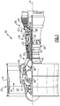
- FIG. 1 schematically illustrates a gas turbine engine 20.
- the gas turbine engine 20 is disclosed herein as a two-spool turbofan that generally incorporates a fan section 22, a compressor section 24, a combustor section 26 and a turbine section 28.
- Alternative engines might include an augmentor section (not shown) among other systems or features.
- the fan section 22 drives air along a bypass flow path B in a bypass duct defined within a nacelle 15, while the compressor section 24 drives air along a core flow path C for compression and communication into the combustor section 26 then expansion through the turbine section 28.
- the exemplary engine 20 generally includes a low speed spool 30 and a high speed spool 32 mounted for rotation about an engine central longitudinal axis A relative to an engine static structure 36 via several bearing systems 38. It should be understood that various bearing systems 38 at various locations may alternatively or additionally be provided, and the location of bearing systems 38 may be varied as appropriate to the application.
- the low speed spool 30 generally includes an inner shaft 40 that interconnects a fan 42, a first (or low) pressure compressor 44 and a second (or low) pressure turbine 46.
- the inner shaft 40 is connected to the fan 42 through a speed change mechanism, which in exemplary gas turbine engine 20 is illustrated as a geared architecture 48 to drive the fan 42 at a lower speed than the low speed spool 30.
- the high speed spool 32 includes an outer shaft 50 that interconnects a second (or high) pressure compressor 52 and a first (or high) pressure turbine 54.
- a combustor 56 is arranged in exemplary gas turbine 20 between the high pressure compressor 52 and the high pressure turbine 54.
- a mid-turbine frame 57 of the engine static structure 36 is arranged generally between the high pressure turbine 54 and the low pressure turbine 46.
- the mid-turbine frame 57 further supports bearing systems 38 in the turbine section 28.
- the inner shaft 40 and the outer shaft 50 are concentric and rotate via bearing systems 38 about the engine central longitudinal axis A which is collinear with their longitudinal axes.
- the core airflow is compressed by the low pressure compressor 44 then the high pressure compressor 52, mixed and burned with fuel in the combustor 56, then expanded over the high pressure turbine 54 and low pressure turbine 46.
- the mid-turbine frame 57 includes airfoils 59 which are in the core airflow path C.
- the turbines 46, 54 rotationally drive the respective low speed spool 30 and high speed spool 32 in response to the expansion.
- gear system 48 may be located aft of combustor section 26 or even aft of turbine section 28, and fan section 22 may be positioned forward or aft of the location of gear system 48.
- the engine 20 in one example is a high-bypass geared aircraft engine.
- the engine 20 bypass ratio is greater than about six (6:1), with an example embodiment being greater than about ten (10:1)
- the geared architecture 48 is an epicyclic gear train, such as a planetary gear system or other gear system, with a gear reduction ratio of greater than about 2.3:1
- the low pressure turbine 46 has a pressure ratio that is greater than about five (5:1).
- the engine 20 bypass ratio is greater than about ten (10:1)
- the fan diameter is significantly larger than that of the low pressure compressor 44
- the low pressure turbine 46 has a pressure ratio that is greater than about five (5:1).
- Low pressure turbine 46 pressure ratio is pressure measured prior to inlet of low pressure turbine 46 as related to the pressure at the outlet of the low pressure turbine 46 prior to an exhaust nozzle.
- the geared architecture 48 may be an epicycle gear train, such as a planetary gear system or other gear system, with a gear reduction ratio of greater than about 2.3:1. It should be understood, however, that the above parameters are only exemplary of one embodiment of a geared architecture engine and that the present invention is applicable to other gas turbine engines including direct drive turbofans.
- the fan section 22 of the engine 20 is designed for a particular flight condition -- typically cruise at about 0.8 Mach and about 35,000 feet (10,668 m).
- the flight condition of 0.8 Mach and 35,000 ft (10,668 m), with the engine at its best fuel consumption - also known as "bucket cruise Thrust Specific Fuel Consumption ('TSFC')" - is the industry standard parameter of lbm of fuel being burned divided by lbf of thrust the engine produces at that minimum point.
- "Low fan pressure ratio” is the pressure ratio across the fan blade alone, without a Fan Exit Guide Vane (“FEGV”) system.
- the low fan pressure ratio as disclosed herein according to one non-limiting embodiment is less than about 1.45.
- the "Low corrected fan tip speed" as disclosed herein according to one non-limiting embodiment is less than about 1150 ft / second (350.52 m/s).
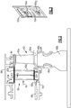
- Figure 2 shows a schematic representation of turbine blade 60 and associated turbine vane 62.
- the blade 60 includes an airfoil 60a that is mounted for rotation with a disk 60b about the engine center axis.
- a coverplate and seal assembly 60c is mounted for rotation with the disk 60b.
- a blade outer air seal (BOAS) 64 is positioned radially outward of a tip of the blade 60 and is coupled to an engine case structure 66.
- BOAS blade outer air seal
- the vane 62 includes an airfoil 62a, an inner platform 62b, and an outer platform 62c that is fixed to the engine case structure 66.
- the airfoil 62a extends between the inner 62b and outer 62c platforms.
- the inner platform 62b is positioned axially between a platform 60d of the blade 60 and a combustor panel 68.
- a combustor liner 70 is mounted to the combustor panel 68 and extends in aft direction toward the vane 62.
- the vane 62 includes baffles 72 that extend between the inner 62b and outer 62c platforms.
- a top view of the outer platform 62c (see arrow 74 in Figure 2 ) is shown in Figure 3 .
- the vane 62 comprises a doublet configuration that is associated with a pair of airfoils 62a 1 and 62a 2 .
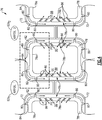
- a front view of the doublet vane configuration (see arrow 76 in Figure 2 ) is shown in Figure 4 .
- a first component, the first airfoil 62a 1 for example, is shown to the left in Figure 4 and a second component, the second airfoil 62a 2 , for example, is shown to the right.
- a schematic representation of a casting 78 of the vane 62 is shown with the baffles 72 to show cooling flow patterns between adjacent airfoils 62a 1 and 62a 2 .
- the castings 78 define external platform surfaces 78a, external airfoil surfaces 78b, and internal airfoil surfaces 78c.
- Baffle standoffs 80 created by the core extend between the casting 78 and the baffles 72.
- the standoffs 80 create channels 82 between outer surfaces of the baffles 72 and the internal airfoil surfaces 78c.
- a gap 84 between baffle edges in the middle of the platform provides an entrance for cooling air flow.
- the air enters the gap 84 and then flows into the channels 82.
- a plurality of holes 86 are formed within the airfoils 62a to extend from the internal surface 78c to the external surface 78b.
- the holes 86 are formed in both a suction side 88 and in a pressure side 90. Flow from the channels 82 enters the holes 86 to cool the airfoils after cooling the platform.
- Figure 5 is a view similar to Figure 4 but shows a ceramic core 92 and wax die 94 used to create the airfoils 62a 1 and 62a 2 .
- Wax 96 is located between the core 92 and die 94.
- a wax die end block 98 fits over the ceramic core 92 and slides radially inwardly and outwardly as indicated at 100.
- Locator pins 102 are used for adjustment purposes to center the core 92 within the wax die 94.
- the wax die end block 98 fits over the core 92 with small gaps 104 to account for locator pin adjustments, tolerances, and growth.
- a mismatch M ( Figure 5 ) could exist due to ceramic core positioning, growth of the ceramic core, and wax die end block positioning. Cores 92 could be mis-positioned closer together or farther apart if the locator pins 102 are not adjusted properly.
- Figure 6 shows a section view as indicated at 106 in Figure 3 and which is similar to Figure 5 , but with the core 92 and wax dies 94 removed.
- cooling flow enters the gap 84 in the middle of the platform and travels into the channels 82 to cool the platform before entering the airfoils.
- a pocket 108 is created in the wax by the core 92 and the end block 98 ( Figure 5 ). This pocket 108 can become shallower or deeper than that which is shown in Figure 6 dependent upon shifting of the core 92 and/or end block 98.
- Figures 7A-7C show a comparison of a nominal pocket 108a ( Figure 7A ), a shallow pocket 108b ( Figure 7B ), and a deep pocket 108c ( Figure 7C ).
- a tolerance range is defined between a first set of tolerances and a second set of tolerances with a nominal tolerance condition being defined between the first and second sets of tolerances.
- a nominal tolerance position 110 is shown for the nominal tolerance condition in Figure 7A , which defines a nominal channel height H1.
- the baffle standoffs 80 force the baffles 72 to move with the core 92. If the core 92 ( Figure 5 ) shifts inward from the nominal position 110, as indicated at 112 in Figure 7B , the baffle 72 moves inward too.
- the wax die end block 98 shifts outward as indicated at 114 and creates a shallow pocket 108b. This reduces cavity height to a minimum height H2 resulting in an increased pressure loss.
- the baffle 72 moves outward too.
- the wax die end block 98 shifts inward as indicated at 118 and creates a deep pocket 108c. This increases cavity height to a maximum height H3 resulting in reduced platform heat transfer.
- a single piece coverplate 120 is used with the baffles 72; however, this configuration can lead to leakage gaps due to radial tolerances.
- a tolerance range is defined between a first set of tolerances and a second set of tolerances with a nominal tolerance condition being defined between the first and second sets of tolerances.
- a nominal tolerance position 122 is shown for the nominal tolerance condition in Figure 8A , which defines a nominal channel height H1.
- the coverplate 120 is fit within the gap 84 and includes a slot 124 that allows cooling air flow to enter the channels 82.
- the coverplate 120 includes coverplate standoffs 126 that force the coverplate 120 to move with the pocket 108a.
- the baffle standoffs 80 force the baffles 72 to move with the core 92.
- the baffle 72 moves inward too.
- the wax die end block 98 shifts outward as indicated at 130 and creates a shallow pocket 108b. This reduces cavity height to a minimum height H2 resulting in an increased pressure loss.
- the shifting of the wax die end block 98 outward also forces the coverplate 120 to shift outwardly of the gap 84, which creates leak gaps 132.
- This baffle/coverplate mismatch allows air to leak between outer edges of the coverplate 120 and the baffles via the leak gaps 132 resulting in reduced platform heat transfer.
- the baffle 72 moves outward too.
- the wax die end block 98 shifts inward as indicated at 136 and creates a deep pocket 108c. This increases cavity height to a maximum height H3.
- the shifting of the wax die end block 98 inward also forces the coverplate 120 to shift inwardly through the gap 84 to create a leak path 138.
- This baffle/coverplate mismatch allows air to leak around the coverplate 120 via the leak paths 138, which reduces platform heat transfer.
- Figures 9A-9C shows the single piece coverplate 120 as affected by core shifting in a circumferential direction. This configuration can lead to leakage gaps due to circumferential tolerances.
- a tolerance range is defined between a first set of tolerances and a second set of tolerances with a nominal tolerance condition being defined between the first and second sets of tolerances.
- a nominal tolerance position 140 is shown for the nominal tolerance condition in Figure 9A .
- the coverplate 120 is fit within the gap 84 and includes the slot 124 that allows cooling air flow to enter the channels 82.
- the gap in Figure 9A defines the nominal width W1 of the gap at the nominal tolerance position 140.
- the coverplate 120 includes coverplate standoffs 126 that force the coverplate 120 to move with the pocket 108a.
- the baffle standoffs 80 force the baffles 72 to move with the core 92.
- the baffles 72 move closer together as indicated at 144.
- the shifting of the baffles 72 toward each other reduces the size of the gap 84 to a minimum width W2. In this minimum tolerance condition the coverplate 120 does not fit within the gap 84.
- the baffles 72 move farther away from each other as indicated at 148.
- the shifting of the baffles 72 away from each other increases the size of the gap 84 to a maximum width W3. In this maximum tolerance condition the coverplate 120 falls through the gap 84 creating leak gaps 150 that result in a reduction of platform heat transfer.
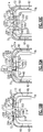
- each coverplate 200 includes at least one coverplate standoff 202 that forces the coverplates 200 to move with the pocket 108a.
- each coverplate 200 includes at least one coverplate radial tab 204.
- the coverplate standoffs 202 extend in a radially inward direction from one side of a plate body and the coverplate radial tabs 204 extend in a radially outward direction from an opposite side of the plate body.
- the coverplate radial tabs 204 are circumferentially offset from the coverplate standoffs 202, i.e. the tabs 204 and standoffs 202 are not radially aligned with each other.
- Each baffle 72 includes a baffle radial tab 206 that abuts directly against the coverplate radial tab 204.
- the baffle radial tabs 206 are positioned circumferentially outward of the coverplate radial tabs 204.
- the coverplate radial tabs 204 are positioned at outer edges 208 of the respective plate bodies. Opposite edges 210 of the plate bodies are spaced apart from each other to form a gap 212 that allows flow to enter the channels 82.
- a tolerance range is defined between a first set of tolerances and a second set of tolerances with a nominal tolerance condition being defined between the first and second sets of tolerances.
- a nominal tolerance position 214 is shown for the nominal tolerance condition in Figure 10A , which defines a nominal channel height H1.
- the coverplates 200 are fit within the gap 84 and are spaced apart to define the inlet gap 212.
- the coverplate standoffs 202 force the coverplates 200 to move in a radial direction with the pocket 108a.
- the baffle standoffs 80 force the baffles 72 to move with the core 92.
- the baffles 72 move inward too.
- the wax die end block 98 shifts outward as indicated at 218 and creates the shallow pocket 108b. This reduces cavity height to a minimum height H2.
- the shifting of the wax die end block 98 outward also forces the coverplates 200 to shift in a radial direction outwardly of the gap 84.
- the coverplate radial tabs 204 shift radially outward relative to the baffle radial tabs 206; however, the tabs 204, 206 are sized such that the tabs 204, 206 remain in direct contact with each other at the minimum height condition to prevent any gaps between the coverplates 200 and baffles 72.
- the tabs 204, 206 also provide a weld attachment surface to secure each coverplate 200 to a respective baffle 72.
- the baffle 72 moves outward too.
- the wax die end block 98 shifts inward as indicated at 222 and creates the deep pocket 108c. This increases cavity height to a maximum height H3.
- the coverplate radial tabs 204 shift radially inward relative to the baffle radial tabs 206; however, the tabs 204, 206 are sized such that the tabs 204, 206 remain in direct contact with each other at the maximum height condition to prevent any gaps between the coverplates 200 and baffles 72.
- the separate coverplates 200 and baffles 72 utilize respective radial tabs 204, 206 to prevent leaks caused by radial tolerances.
- Figures 11A-11C show how the separate coverplates 200 and baffles 72 utilize the respective radial tabs 204, 206 to close gaps caused by circumferential tolerances.
- a tolerance range is defined between a first set of tolerances and a second set of tolerances with a nominal tolerance condition being defined between the first and second sets of tolerances.
- a nominal tolerance position 230 is shown for the nominal tolerance condition in Figure 11A .
- the coverplates 200 are fit within the gap 84 and are spaced apart from each other to define the inlet gap 212 that allows cooling air flow to enter the channels 82.
- the inlet gap 212 in Figure 11A defines the nominal width W1 of the gap 212 at the nominal tolerance position 230.
- the coverplate standoffs 202 force the coverplates 200 to move with the pocket 108a.
- the baffle standoffs 80 force the baffles 72 to move with the core 92.
- the baffles 72 move closer together as indicated at 234.
- the shifting of the baffles 72 toward each other also shifts the coverplates 200 closer to each other and reduces the size of the gap 212 to a minimum width W2. In this minimum tolerance condition cooling air can still enter the channels 82.
- the baffles 72 move farther away from each other as indicated at 238.
- the shifting of the baffles 72 away from each other also shifts the coverplates 200 away from each other and increases the size of the gap 212 to a maximum width W3.
- the radial tabs 204, 206 of the respective coverplates 200 and baffles 72 remain in direct contact with each other during the shifting of the baffles 72 and cores 92 in the circumferential direction to close out any potential leak paths or gaps.
- the subject invention splits a conventional coverplate into two separate coverplates and incorporates standoffs on the coverplates so that if the inner platform surface is out of place due to tolerances, the coverplates move with the surface, maintaining the correct channel height. Similarly, channel height in the airfoil can be maintained by the standard practice of using baffle standoffs created by the core. If the core position is out of place during the casting process due to core shift or tolerances, the baffle will be positioned accordingly by the baffle standoffs. As there are two coverplates, each coverplate can be mated with the corresponding baffle as the baffle position is varied part-to-part due to circumferential core shift and tolerances.
- the subject invention also incorporates radial tabs on both the coverplates and the baffles.
- the radial tabs are long enough to prevent any leakage gaps from opening up due to variation part-to-part in radial core position.
Landscapes
- Engineering & Computer Science (AREA)
- Mechanical Engineering (AREA)
- General Engineering & Computer Science (AREA)
- Physics & Mathematics (AREA)
- Fluid Mechanics (AREA)
- Turbine Rotor Nozzle Sealing (AREA)
Claims (14)
- Gasturbinentriebwerksleitschaufel (62), Folgendes umfassend:eine erste Tragfläche (62a1);eine zweite Tragfläche (62a2), die in Bezug auf eine zentrale Triebwerksachse von der ersten Tragfläche (62a1) umlaufend beabstandet ist, wobei die Leitschaufel (62) eine Doppelkonfiguration umfasst, die mit der ersten Tragfläche (62a1) und der zweiten Tragfläche (62a2) assoziiert ist;eine innere Plattform (62b);eine äußere Plattform (62c);einen ersten Prallkühleinsatz (72), der mit der ersten Tragfläche (62a1) assoziiert ist,einen zweiten Prallkühleinsatz (72), der mit der zweiten Tragfläche (62a2) assoziiert ist, wobei jeder des ersten und des zweiten Prallkühleinsatzes (72) sich zwischen der inneren und äußeren Plattform (62b, 62c) erstreckt, und wobei jeder des ersten und des zweiten Prallkühleinsatzes (72) mindestens eine radiale Prallkühleinsatznase (206) beinhaltet;einen Spalt (212) zwischen dem ersten und dem zweiten Prallkühleinsatz (72), um einen Kühlungslufteinlass zu definieren;eine erste Abdeckplatte (200), die mit dem ersten Prallkühleinsatz (72) assoziiert ist, um einen ersten Abschnitt des Spalts (212) abzudecken; undeine zweite Abdeckplatte (200), die mit dem zweiten Prallkühleinsatz (72) assoziiert ist, um einen zweiten Abschnitt des Spalts (212) abzudecken, wobei die erste und die zweite Abdeckplatte (200) voneinander getrennt sind, und wobei jede der ersten und der zweiten Abdeckplatte (200) mindestens eine radiale Abdeckungsnase (204) beinhaltet, die mit mindestens einer assoziierten Prallkühleinsatznase (206) zusammenwirkt, um Leckspalten zwischen dem ersten und dem zweiten Prallkühleinsatz (72) und der ersten und der zweiten Abdeckplatte (200) zu verhindern.
- Leitschaufel nach Anspruch 1, wobei ein Toleranzbereich zwischen einem ersten Satz von Toleranzen und einem zweiten Satz von Toleranzen definiert ist und ein nominaler Toleranzzustand zwischen dem ersten und dem zweiten Satz von Toleranzen definiert ist, und wobei ein Kanal (82) zwischen einer Prallkühleinsatzfläche des ersten und des zweiten Prallkühleinsatzes (72) und einer Fläche der ersten und der zweiten Tragfläche bereitgestellt ist, und wobei die nominale Kanalhöhe (H1) bei dem nominalen Toleranzzustand definiert ist, und wobei
die mindestens eine radiale Prallkühleinsatznase (206) und die mindestens eine radiale Abdeckplattennase (204) sich in dem nominalen Toleranzzustand in einer ersten Position in Bezug auf einander befinden,
bei dem ersten Satz von Toleranzen, die mindestens eine radiale Prallkühleinsatznase (206) und die mindestens eine radiale Abdeckplattennase (204) sich in einer zweiten Position befinden, wobei, die radiale Abdeckplattennase (204) sich radial nach außen von der ersten Position befindet und die radiale Prallkühleinsatznase (206) sich radial nach innen von der ersten Position befindet, und
bei dem zweiten Satz von Toleranzen, die mindestens eine radiale Prallkühleinsatznase (206) und die mindestens eine radiale Abdeckplattennase (204) sich in einer dritten Position befinden, wobei die radiale Abdeckplattennase (204) sich radial nach innen von der ersten Position befindet und die radiale Prallkühleinsatznase (206) sich radial nach außen von der ersten Position befindet. - Leitschaufel nach Anspruch 1 oder 2, wobei ein Toleranzbereich zwischen einem ersten Satz von Toleranzen und einem zweiten Satz von Toleranzen definiert ist und ein nominaler Toleranzzustand zwischen dem ersten und dem zweiten Satz von Toleranzen definiert ist, und wobei ein Plattenspalt (212) zwischen der ersten und der zweiten Abdeckplatte (200) bereitgestellt ist, und wobei ein nominaler Plattenspalt bei dem nominalen Toleranzzustand definiert ist, und wobei
der Plattenspalt (212) in dem nominalen Toleranzzustand durch einen ersten Abstand (W1) definiert ist,
der Plattenspalt (212) bei dem ersten Satz von Toleranzen durch einen zweiten Abstand (W2) definiert ist, der in Bezug auf den ersten Abstand (W1) umlaufend verkleinert ist, und
der Plattenspalt (212) bei dem zweiten Satz von Toleranzen durch einen dritten Abstand (W3) definiert ist, der in Bezug auf den ersten Abstand (W1) umlaufend vergrößert ist. - Leitschaufel nach einem der Ansprüche 1 bis 3, wobei die erste Tragfläche und die zweite Tragfläche sich von der inneren Plattform (62b) erstrecken.
- Gasturbinentriebwerk (20), Folgendes umfassend:einen Kompressorbereich (24), der eine zentrale Triebwerksachse (A) definiert; undeinen Turbinenbereich (28), stromabwärts des Kompressorbereichs (24), wobei der Turbinenbereich (28) eine Vielzahl von Leitschaufeln (62) nach Anspruch 1 beinhaltet, die umlaufend aneinander angebracht sind, um eine Anordnung von Leitschaufeln zu bilden.
- Gasturbinentriebwerk oder Leitschaufel nach Anspruch 4 oder 5, wobei der erste oder der zweite Prallkühleinsatz (72) eine Prallkühleinsatzfläche beinhaltet, die einer Leitschaufelfläche oder einer Tragfläche (78c) zugewandt ist, und Kanäle (82) beinhaltend, die zwischen dem Prallkühleinsatz (72) und der Leitschaufel- oder der Tragflächenfläche (78c) gebildet sind, und wobei die erste und die zweite Abdeckplatte (200) innerhalb des Spalts (212) positioniert und voneinander beabstandet sind, um einen Kühlungslufteinlass in die Kanäle (82) zu definieren.
- Gasturbinentriebwerk oder Leitschaufel nach Anspruch 6, wobei die radialen Abdeckplattennasen (204) und die radialen Prallkühleinsatznasen (206) in Bezug auf einander an verschiedenen radialen Positionen positioniert sind, um eine gewünschte Kanalhöhe (H1, H2, H3) durch den Toleranzbereich hinweg aufrechtzuerhalten, der durch die erste und die zweite Tragfläche (62a1, 62a2) definiert ist.
- Gasturbinentriebwerk oder Leitschaufel nach Anspruch 7, wobei der Kühlungslufteinlass in einer umlaufenden Richtung durch den Toleranzbereich hinweg variiert.
- Gasturbinentriebwerk oder Leitschaufel nach Anspruch 8, wobei der Kühlungslufteinlass, wenn die Tragflächen (62a1, 62a2) umlaufend näher aneinander positioniert sind, sich in Bezug auf eine nominale Toleranzgröße in der Größe verkleinert, als wenn die Tragflächen (62a1, 62a2) bei einem nominalen Toleranzabstand positioniert sind.
- Gasturbinentriebwerk oder Leitschaufel nach Anspruch 9, wobei der Kühlungslufteinlass, wenn die Tragflächen (62a1, 62a2) umlaufend weiter voneinander entfernt positioniert sind, sich in Bezug auf eine nominale Toleranzgröße in der Größe vergrößert, als wenn die Tragflächen (62a1, 62a2) bei einem nominalen Toleranzabstand positioniert sind.
- Gasturbinentriebwerk oder Leitschaufel nach einem der vorstehenden Ansprüche, wobei die erste und die zweite Abdeckplatte (200) jeweils mindestens ein Plattenabstandsteil (202) beinhalten, das sich in einer radialen Richtung erstreckt, die der mindestens einen radialen Abdeckplattennase (204) gegenüberliegt.
- Gasturbinentriebwerk oder Leitschaufel nach Anspruch 11, wobei das mindestens eine Plattenabstandsteil (202) und die mindestens eine Plattennase der Abdeckplatte (204) umlaufend voneinander versetzt sind.
- Gasturbinentriebwerk oder Leitschaufel nach einem der vorstehenden Ansprüche, wobei die assoziierten radialen Abdeckplattennasen (204) und radialen Prallkühleinsatznasen (206) in direkt berührendem Eingriff miteinander stehen.
- Gasturbinentriebwerk oder Leitschaufel nach einem der vorstehenden Ansprüche, wobei jede der ersten und der zweiten Abdeckplatte (200) eine Basisplatte beinhaltet, die sich zwischen umlaufend beabstandeten Kanten mit mindestens einer radialen Plattennase (204) erstreckt, die sich radial nach außen von einer der Kanten erstreckt.
Applications Claiming Priority (1)
| Application Number | Priority Date | Filing Date | Title |
|---|---|---|---|
| US14/641,470 US9771814B2 (en) | 2015-03-09 | 2015-03-09 | Tolerance resistance coverplates |
Publications (2)
| Publication Number | Publication Date |
|---|---|
| EP3067521A1 EP3067521A1 (de) | 2016-09-14 |
| EP3067521B1 true EP3067521B1 (de) | 2019-05-08 |
Family
ID=55589659
Family Applications (1)
| Application Number | Title | Priority Date | Filing Date |
|---|---|---|---|
| EP16159496.5A Active EP3067521B1 (de) | 2015-03-09 | 2016-03-09 | Turbinenleitschaufel mit prallkühleinsätzen mit abdeckplatten für variierende toleranzen |
Country Status (2)
| Country | Link |
|---|---|
| US (1) | US9771814B2 (de) |
| EP (1) | EP3067521B1 (de) |
Family Cites Families (23)
| Publication number | Priority date | Publication date | Assignee | Title |
|---|---|---|---|---|
| US3936216A (en) | 1974-03-21 | 1976-02-03 | United Technologies Corporation | Blade sealing and retaining means |
| US3990812A (en) | 1975-03-03 | 1976-11-09 | United Technologies Corporation | Radial inflow blade cooling system |
| DE3003347A1 (de) * | 1979-12-20 | 1981-06-25 | BBC AG Brown, Boveri & Cie., Baden, Aargau | Gekuehlte wand |
| US6418618B1 (en) | 2000-04-11 | 2002-07-16 | General Electric Company | Method of controlling the side wall thickness of a turbine nozzle segment for improved cooling |
| US6386825B1 (en) | 2000-04-11 | 2002-05-14 | General Electric Company | Apparatus and methods for impingement cooling of a side wall of a turbine nozzle segment |
| US6398486B1 (en) * | 2000-06-01 | 2002-06-04 | General Electric Company | Steam exit flow design for aft cavities of an airfoil |
| EP1557535A1 (de) * | 2004-01-20 | 2005-07-27 | Siemens Aktiengesellschaft | Turbinenschaufel und Gasturbine mit einer solchen Turbinenschaufel |
| US7104756B2 (en) * | 2004-08-11 | 2006-09-12 | United Technologies Corporation | Temperature tolerant vane assembly |
| US8123466B2 (en) | 2007-03-01 | 2012-02-28 | United Technologies Corporation | Blade outer air seal |
| US8439629B2 (en) | 2007-03-01 | 2013-05-14 | United Technologies Corporation | Blade outer air seal |
| US20090067978A1 (en) | 2007-05-24 | 2009-03-12 | Suljak Jr George T | Variable area turbine vane arrangement |
| US8708652B2 (en) | 2007-06-27 | 2014-04-29 | United Technologies Corporation | Cover plate for turbine rotor having enclosed pump for cooling air |
| US8562285B2 (en) | 2007-07-02 | 2013-10-22 | United Technologies Corporation | Angled on-board injector |
| US8313289B2 (en) | 2007-12-07 | 2012-11-20 | United Technologies Corp. | Gas turbine engine systems involving rotor bayonet coverplates and tools for installing such coverplates |
| US8393867B2 (en) * | 2008-03-31 | 2013-03-12 | United Technologies Corporation | Chambered airfoil cooling |
| US8651802B2 (en) | 2010-03-17 | 2014-02-18 | United Technologies Corporation | Cover plate for turbine vane assembly |
| US8870544B2 (en) | 2010-07-29 | 2014-10-28 | United Technologies Corporation | Rotor cover plate retention method |
| US8740554B2 (en) | 2011-01-11 | 2014-06-03 | United Technologies Corporation | Cover plate with interstage seal for a gas turbine engine |
| JP5931351B2 (ja) | 2011-05-13 | 2016-06-08 | 三菱重工業株式会社 | タービン静翼 |
| US8864445B2 (en) | 2012-01-09 | 2014-10-21 | General Electric Company | Turbine nozzle assembly methods |
| US9011079B2 (en) | 2012-01-09 | 2015-04-21 | General Electric Company | Turbine nozzle compartmentalized cooling system |
| US9303521B2 (en) | 2012-09-27 | 2016-04-05 | United Technologies Corporation | Interstage coverplate assembly for arranging between adjacent rotor stages of a rotor assembly |
| US9677407B2 (en) | 2013-01-09 | 2017-06-13 | United Technologies Corporation | Rotor cover plate |
-
2015
- 2015-03-09 US US14/641,470 patent/US9771814B2/en active Active
-
2016
- 2016-03-09 EP EP16159496.5A patent/EP3067521B1/de active Active
Non-Patent Citations (1)
| Title |
|---|
| None * |
Also Published As
| Publication number | Publication date |
|---|---|
| EP3067521A1 (de) | 2016-09-14 |
| US9771814B2 (en) | 2017-09-26 |
| US20160265372A1 (en) | 2016-09-15 |
Similar Documents
| Publication | Publication Date | Title |
|---|---|---|
| EP3734018B1 (de) | Dichtung für ein gasturbinentriebwerks-bauteil und zugehöriges verfahren | |
| US11035236B2 (en) | Baffle for a component of a gas turbine engine | |
| EP3063389B1 (de) | Bohrungsgekühlte filmspendende sockel | |
| EP3043027B1 (de) | Gasturbinenmotorkomponente mit konformem kehlkühlungspfad | |
| EP2977555B1 (de) | Schaufelplattform mit kühlkanäle | |
| EP3084136B1 (de) | Laufschaufel und zugehöriges verfahren zur kühlung einer plattform einer laufschaufel | |
| EP2993304B1 (de) | Gasturbinenmotorkomponente mit filmkühlungsloch | |
| EP3181823B1 (de) | Verfahren und vorrichtung zur kühlung einer gasturbinenmotorschaufel | |
| EP3514331B1 (de) | Gekühltes schaufelblatt und zugehöriges gasturbinentriebwerk | |
| EP2971585B1 (de) | Schienendichtung für eine gasturbinenschaufel | |
| EP3078807B1 (de) | Kühlkanäle für eine gasturbinenmotorkomponente | |
| EP3054094B1 (de) | Gasturbinenmotorturbinenschaufelablenkplatte und schlangenförmiger kühlkanal | |
| EP3514332A1 (de) | Zweiwandiger prallhohlraum für gasturbinenmotorkomponenten | |
| EP3045666B1 (de) | Tragflächenplattform mit kühlungseinspeisungsöffnungen | |
| EP3495614B1 (de) | Gekühlte gasturbinenkomponente | |
| EP3450693B1 (de) | Dichtungsanordnung für die schnittstelle zwischen brennkammer und leitschaufel | |
| EP3450692B1 (de) | Dichtungsanordnung für die schnittstelle zwischen brennkammer und leitschaufel | |
| EP2927429B1 (de) | Gasturbinenkomponente mit flusstrennungsrippe | |
| EP3023596B1 (de) | Innengekühlte turbinenplattform | |
| EP3067521B1 (de) | Turbinenleitschaufel mit prallkühleinsätzen mit abdeckplatten für variierende toleranzen | |
| EP3508693B1 (de) | Segregierte kühlluftkanäle für turbinenschaufel | |
| EP2961964B1 (de) | Bauteil eines gasturbinentriebwerks und zugehöriges verfahren zur herstellung einer öffnung | |
| EP3502417B1 (de) | Ströumungsumlenkelemente einer plattform für gasturbinenmotorkomponenten | |
| EP3581762B1 (de) | Kühlkanalanordnung für gasturbinendeckband | |
| EP2975222A1 (de) | Gekühlte tasche in einer turbinenschaufelplattform |
Legal Events
| Date | Code | Title | Description |
|---|---|---|---|
| PUAI | Public reference made under article 153(3) epc to a published international application that has entered the european phase |
Free format text: ORIGINAL CODE: 0009012 |
|
| AK | Designated contracting states |
Kind code of ref document: A1 Designated state(s): AL AT BE BG CH CY CZ DE DK EE ES FI FR GB GR HR HU IE IS IT LI LT LU LV MC MK MT NL NO PL PT RO RS SE SI SK SM TR |
|
| AX | Request for extension of the european patent |
Extension state: BA ME |
|
| RAP1 | Party data changed (applicant data changed or rights of an application transferred) |
Owner name: UNITED TECHNOLOGIES CORPORATION |
|
| RIN1 | Information on inventor provided before grant (corrected) |
Inventor name: DEGRAY, JEFFREY J. Inventor name: WAITE, RYAN ALAN Inventor name: DZIUBA, THOMAS P. Inventor name: SPANGLER, BRANDON W. Inventor name: CAVALLO, GINA Inventor name: VU, KY H. |
|
| STAA | Information on the status of an ep patent application or granted ep patent |
Free format text: STATUS: REQUEST FOR EXAMINATION WAS MADE |
|
| 17P | Request for examination filed |
Effective date: 20170314 |
|
| RBV | Designated contracting states (corrected) |
Designated state(s): AL AT BE BG CH CY CZ DE DK EE ES FI FR GB GR HR HU IE IS IT LI LT LU LV MC MK MT NL NO PL PT RO RS SE SI SK SM TR |
|
| GRAP | Despatch of communication of intention to grant a patent |
Free format text: ORIGINAL CODE: EPIDOSNIGR1 |
|
| STAA | Information on the status of an ep patent application or granted ep patent |
Free format text: STATUS: GRANT OF PATENT IS INTENDED |
|
| INTG | Intention to grant announced |
Effective date: 20181119 |
|
| RIN1 | Information on inventor provided before grant (corrected) |
Inventor name: DZIUBA, THOMAS P. Inventor name: WAITE, RYAN ALAN Inventor name: DEGRAY, JEFFREY J. Inventor name: SPANGLER, BRANDON W. Inventor name: CAVALLO, GINA Inventor name: VU, KY H. |
|
| GRAS | Grant fee paid |
Free format text: ORIGINAL CODE: EPIDOSNIGR3 |
|
| GRAA | (expected) grant |
Free format text: ORIGINAL CODE: 0009210 |
|
| STAA | Information on the status of an ep patent application or granted ep patent |
Free format text: STATUS: THE PATENT HAS BEEN GRANTED |
|
| AK | Designated contracting states |
Kind code of ref document: B1 Designated state(s): AL AT BE BG CH CY CZ DE DK EE ES FI FR GB GR HR HU IE IS IT LI LT LU LV MC MK MT NL NO PL PT RO RS SE SI SK SM TR |
|
| REG | Reference to a national code |
Ref country code: GB Ref legal event code: FG4D |
|
| REG | Reference to a national code |
Ref country code: CH Ref legal event code: EP Ref country code: AT Ref legal event code: REF Ref document number: 1130411 Country of ref document: AT Kind code of ref document: T Effective date: 20190515 |
|
| REG | Reference to a national code |
Ref country code: IE Ref legal event code: FG4D |
|
| REG | Reference to a national code |
Ref country code: DE Ref legal event code: R096 Ref document number: 602016013445 Country of ref document: DE |
|
| REG | Reference to a national code |
Ref country code: NL Ref legal event code: MP Effective date: 20190508 |
|
| REG | Reference to a national code |
Ref country code: LT Ref legal event code: MG4D |
|
| PG25 | Lapsed in a contracting state [announced via postgrant information from national office to epo] |
Ref country code: ES Free format text: LAPSE BECAUSE OF FAILURE TO SUBMIT A TRANSLATION OF THE DESCRIPTION OR TO PAY THE FEE WITHIN THE PRESCRIBED TIME-LIMIT Effective date: 20190508 Ref country code: LT Free format text: LAPSE BECAUSE OF FAILURE TO SUBMIT A TRANSLATION OF THE DESCRIPTION OR TO PAY THE FEE WITHIN THE PRESCRIBED TIME-LIMIT Effective date: 20190508 Ref country code: NL Free format text: LAPSE BECAUSE OF FAILURE TO SUBMIT A TRANSLATION OF THE DESCRIPTION OR TO PAY THE FEE WITHIN THE PRESCRIBED TIME-LIMIT Effective date: 20190508 Ref country code: FI Free format text: LAPSE BECAUSE OF FAILURE TO SUBMIT A TRANSLATION OF THE DESCRIPTION OR TO PAY THE FEE WITHIN THE PRESCRIBED TIME-LIMIT Effective date: 20190508 Ref country code: HR Free format text: LAPSE BECAUSE OF FAILURE TO SUBMIT A TRANSLATION OF THE DESCRIPTION OR TO PAY THE FEE WITHIN THE PRESCRIBED TIME-LIMIT Effective date: 20190508 Ref country code: AL Free format text: LAPSE BECAUSE OF FAILURE TO SUBMIT A TRANSLATION OF THE DESCRIPTION OR TO PAY THE FEE WITHIN THE PRESCRIBED TIME-LIMIT Effective date: 20190508 Ref country code: PT Free format text: LAPSE BECAUSE OF FAILURE TO SUBMIT A TRANSLATION OF THE DESCRIPTION OR TO PAY THE FEE WITHIN THE PRESCRIBED TIME-LIMIT Effective date: 20190908 Ref country code: NO Free format text: LAPSE BECAUSE OF FAILURE TO SUBMIT A TRANSLATION OF THE DESCRIPTION OR TO PAY THE FEE WITHIN THE PRESCRIBED TIME-LIMIT Effective date: 20190808 Ref country code: SE Free format text: LAPSE BECAUSE OF FAILURE TO SUBMIT A TRANSLATION OF THE DESCRIPTION OR TO PAY THE FEE WITHIN THE PRESCRIBED TIME-LIMIT Effective date: 20190508 |
|
| PG25 | Lapsed in a contracting state [announced via postgrant information from national office to epo] |
Ref country code: RS Free format text: LAPSE BECAUSE OF FAILURE TO SUBMIT A TRANSLATION OF THE DESCRIPTION OR TO PAY THE FEE WITHIN THE PRESCRIBED TIME-LIMIT Effective date: 20190508 Ref country code: LV Free format text: LAPSE BECAUSE OF FAILURE TO SUBMIT A TRANSLATION OF THE DESCRIPTION OR TO PAY THE FEE WITHIN THE PRESCRIBED TIME-LIMIT Effective date: 20190508 Ref country code: GR Free format text: LAPSE BECAUSE OF FAILURE TO SUBMIT A TRANSLATION OF THE DESCRIPTION OR TO PAY THE FEE WITHIN THE PRESCRIBED TIME-LIMIT Effective date: 20190809 Ref country code: BG Free format text: LAPSE BECAUSE OF FAILURE TO SUBMIT A TRANSLATION OF THE DESCRIPTION OR TO PAY THE FEE WITHIN THE PRESCRIBED TIME-LIMIT Effective date: 20190808 |
|
| REG | Reference to a national code |
Ref country code: AT Ref legal event code: MK05 Ref document number: 1130411 Country of ref document: AT Kind code of ref document: T Effective date: 20190508 |
|
| PG25 | Lapsed in a contracting state [announced via postgrant information from national office to epo] |
Ref country code: AT Free format text: LAPSE BECAUSE OF FAILURE TO SUBMIT A TRANSLATION OF THE DESCRIPTION OR TO PAY THE FEE WITHIN THE PRESCRIBED TIME-LIMIT Effective date: 20190508 Ref country code: RO Free format text: LAPSE BECAUSE OF FAILURE TO SUBMIT A TRANSLATION OF THE DESCRIPTION OR TO PAY THE FEE WITHIN THE PRESCRIBED TIME-LIMIT Effective date: 20190508 Ref country code: CZ Free format text: LAPSE BECAUSE OF FAILURE TO SUBMIT A TRANSLATION OF THE DESCRIPTION OR TO PAY THE FEE WITHIN THE PRESCRIBED TIME-LIMIT Effective date: 20190508 Ref country code: SK Free format text: LAPSE BECAUSE OF FAILURE TO SUBMIT A TRANSLATION OF THE DESCRIPTION OR TO PAY THE FEE WITHIN THE PRESCRIBED TIME-LIMIT Effective date: 20190508 Ref country code: EE Free format text: LAPSE BECAUSE OF FAILURE TO SUBMIT A TRANSLATION OF THE DESCRIPTION OR TO PAY THE FEE WITHIN THE PRESCRIBED TIME-LIMIT Effective date: 20190508 Ref country code: DK Free format text: LAPSE BECAUSE OF FAILURE TO SUBMIT A TRANSLATION OF THE DESCRIPTION OR TO PAY THE FEE WITHIN THE PRESCRIBED TIME-LIMIT Effective date: 20190508 |
|
| REG | Reference to a national code |
Ref country code: DE Ref legal event code: R097 Ref document number: 602016013445 Country of ref document: DE |
|
| PG25 | Lapsed in a contracting state [announced via postgrant information from national office to epo] |
Ref country code: SM Free format text: LAPSE BECAUSE OF FAILURE TO SUBMIT A TRANSLATION OF THE DESCRIPTION OR TO PAY THE FEE WITHIN THE PRESCRIBED TIME-LIMIT Effective date: 20190508 Ref country code: IT Free format text: LAPSE BECAUSE OF FAILURE TO SUBMIT A TRANSLATION OF THE DESCRIPTION OR TO PAY THE FEE WITHIN THE PRESCRIBED TIME-LIMIT Effective date: 20190508 |
|
| PLBE | No opposition filed within time limit |
Free format text: ORIGINAL CODE: 0009261 |
|
| STAA | Information on the status of an ep patent application or granted ep patent |
Free format text: STATUS: NO OPPOSITION FILED WITHIN TIME LIMIT |
|
| PG25 | Lapsed in a contracting state [announced via postgrant information from national office to epo] |
Ref country code: TR Free format text: LAPSE BECAUSE OF FAILURE TO SUBMIT A TRANSLATION OF THE DESCRIPTION OR TO PAY THE FEE WITHIN THE PRESCRIBED TIME-LIMIT Effective date: 20190508 |
|
| 26N | No opposition filed |
Effective date: 20200211 |
|
| PG25 | Lapsed in a contracting state [announced via postgrant information from national office to epo] |
Ref country code: PL Free format text: LAPSE BECAUSE OF FAILURE TO SUBMIT A TRANSLATION OF THE DESCRIPTION OR TO PAY THE FEE WITHIN THE PRESCRIBED TIME-LIMIT Effective date: 20190508 |
|
| PG25 | Lapsed in a contracting state [announced via postgrant information from national office to epo] |
Ref country code: SI Free format text: LAPSE BECAUSE OF FAILURE TO SUBMIT A TRANSLATION OF THE DESCRIPTION OR TO PAY THE FEE WITHIN THE PRESCRIBED TIME-LIMIT Effective date: 20190508 |
|
| PG25 | Lapsed in a contracting state [announced via postgrant information from national office to epo] |
Ref country code: MC Free format text: LAPSE BECAUSE OF FAILURE TO SUBMIT A TRANSLATION OF THE DESCRIPTION OR TO PAY THE FEE WITHIN THE PRESCRIBED TIME-LIMIT Effective date: 20190508 |
|
| REG | Reference to a national code |
Ref country code: CH Ref legal event code: PL |
|
| REG | Reference to a national code |
Ref country code: BE Ref legal event code: MM Effective date: 20200331 |
|
| PG25 | Lapsed in a contracting state [announced via postgrant information from national office to epo] |
Ref country code: LU Free format text: LAPSE BECAUSE OF NON-PAYMENT OF DUE FEES Effective date: 20200309 |
|
| PG25 | Lapsed in a contracting state [announced via postgrant information from national office to epo] |
Ref country code: CH Free format text: LAPSE BECAUSE OF NON-PAYMENT OF DUE FEES Effective date: 20200331 Ref country code: LI Free format text: LAPSE BECAUSE OF NON-PAYMENT OF DUE FEES Effective date: 20200331 Ref country code: IE Free format text: LAPSE BECAUSE OF NON-PAYMENT OF DUE FEES Effective date: 20200309 |
|
| PG25 | Lapsed in a contracting state [announced via postgrant information from national office to epo] |
Ref country code: BE Free format text: LAPSE BECAUSE OF NON-PAYMENT OF DUE FEES Effective date: 20200331 |
|
| PG25 | Lapsed in a contracting state [announced via postgrant information from national office to epo] |
Ref country code: MT Free format text: LAPSE BECAUSE OF FAILURE TO SUBMIT A TRANSLATION OF THE DESCRIPTION OR TO PAY THE FEE WITHIN THE PRESCRIBED TIME-LIMIT Effective date: 20190508 Ref country code: CY Free format text: LAPSE BECAUSE OF FAILURE TO SUBMIT A TRANSLATION OF THE DESCRIPTION OR TO PAY THE FEE WITHIN THE PRESCRIBED TIME-LIMIT Effective date: 20190508 |
|
| PG25 | Lapsed in a contracting state [announced via postgrant information from national office to epo] |
Ref country code: MK Free format text: LAPSE BECAUSE OF FAILURE TO SUBMIT A TRANSLATION OF THE DESCRIPTION OR TO PAY THE FEE WITHIN THE PRESCRIBED TIME-LIMIT Effective date: 20190508 Ref country code: IS Free format text: LAPSE BECAUSE OF FAILURE TO SUBMIT A TRANSLATION OF THE DESCRIPTION OR TO PAY THE FEE WITHIN THE PRESCRIBED TIME-LIMIT Effective date: 20190908 |
|
| REG | Reference to a national code |
Ref country code: DE Ref legal event code: R081 Ref document number: 602016013445 Country of ref document: DE Owner name: RAYTHEON TECHNOLOGIES CORPORATION (N.D.GES.D.S, US Free format text: FORMER OWNER: UNITED TECHNOLOGIES CORPORATION, FARMINGTON, CONN., US Ref country code: DE Ref legal event code: R081 Ref document number: 602016013445 Country of ref document: DE Owner name: RTX CORPORATION (N.D.GES.D. STAATES DELAWARE),, US Free format text: FORMER OWNER: UNITED TECHNOLOGIES CORPORATION, FARMINGTON, CONN., US |
|
| P01 | Opt-out of the competence of the unified patent court (upc) registered |
Effective date: 20230520 |
|
| REG | Reference to a national code |
Ref country code: DE Ref legal event code: R081 Ref document number: 602016013445 Country of ref document: DE Owner name: RTX CORPORATION (N.D.GES.D. STAATES DELAWARE),, US Free format text: FORMER OWNER: RAYTHEON TECHNOLOGIES CORPORATION (N.D.GES.D.STAATES DELAWARE), ARLINGTON, VA, US |
|
| PGFP | Annual fee paid to national office [announced via postgrant information from national office to epo] |
Ref country code: GB Payment date: 20260219 Year of fee payment: 11 |
|
| PGFP | Annual fee paid to national office [announced via postgrant information from national office to epo] |
Ref country code: DE Payment date: 20260219 Year of fee payment: 11 |
|
| PGFP | Annual fee paid to national office [announced via postgrant information from national office to epo] |
Ref country code: FR Payment date: 20260219 Year of fee payment: 11 |