EP3067536A1 - Verfahren zum Betrieb einer Gasturbine - Google Patents
Verfahren zum Betrieb einer Gasturbine Download PDFInfo
- Publication number
- EP3067536A1 EP3067536A1 EP15158140.2A EP15158140A EP3067536A1 EP 3067536 A1 EP3067536 A1 EP 3067536A1 EP 15158140 A EP15158140 A EP 15158140A EP 3067536 A1 EP3067536 A1 EP 3067536A1
- Authority
- EP
- European Patent Office
- Prior art keywords
- combustion chamber
- compressor
- oxidizer
- gas turbine
- burners
- Prior art date
- Legal status (The legal status is an assumption and is not a legal conclusion. Google has not performed a legal analysis and makes no representation as to the accuracy of the status listed.)
- Withdrawn
Links
Images

Classifications
-
- F—MECHANICAL ENGINEERING; LIGHTING; HEATING; WEAPONS; BLASTING
- F02—COMBUSTION ENGINES; HOT-GAS OR COMBUSTION-PRODUCT ENGINE PLANTS
- F02C—GAS-TURBINE PLANTS; AIR INTAKES FOR JET-PROPULSION PLANTS; CONTROLLING FUEL SUPPLY IN AIR-BREATHING JET-PROPULSION PLANTS
- F02C9/00—Controlling gas-turbine plants; Controlling fuel supply in air- breathing jet-propulsion plants
- F02C9/16—Control of working fluid flow
- F02C9/20—Control of working fluid flow by throttling; by adjusting vanes
- F02C9/22—Control of working fluid flow by throttling; by adjusting vanes by adjusting turbine vanes
-
- F—MECHANICAL ENGINEERING; LIGHTING; HEATING; WEAPONS; BLASTING
- F02—COMBUSTION ENGINES; HOT-GAS OR COMBUSTION-PRODUCT ENGINE PLANTS
- F02C—GAS-TURBINE PLANTS; AIR INTAKES FOR JET-PROPULSION PLANTS; CONTROLLING FUEL SUPPLY IN AIR-BREATHING JET-PROPULSION PLANTS
- F02C9/00—Controlling gas-turbine plants; Controlling fuel supply in air- breathing jet-propulsion plants
- F02C9/26—Control of fuel supply
- F02C9/28—Regulating systems responsive to plant or ambient parameters, e.g. temperature, pressure, rotor speed
-
- F—MECHANICAL ENGINEERING; LIGHTING; HEATING; WEAPONS; BLASTING
- F02—COMBUSTION ENGINES; HOT-GAS OR COMBUSTION-PRODUCT ENGINE PLANTS
- F02C—GAS-TURBINE PLANTS; AIR INTAKES FOR JET-PROPULSION PLANTS; CONTROLLING FUEL SUPPLY IN AIR-BREATHING JET-PROPULSION PLANTS
- F02C9/00—Controlling gas-turbine plants; Controlling fuel supply in air- breathing jet-propulsion plants
- F02C9/48—Control of fuel supply conjointly with another control of the plant
- F02C9/50—Control of fuel supply conjointly with another control of the plant with control of working fluid flow
- F02C9/54—Control of fuel supply conjointly with another control of the plant with control of working fluid flow by throttling the working fluid, by adjusting vanes
-
- F—MECHANICAL ENGINEERING; LIGHTING; HEATING; WEAPONS; BLASTING
- F01—MACHINES OR ENGINES IN GENERAL; ENGINE PLANTS IN GENERAL; STEAM ENGINES
- F01K—STEAM ENGINE PLANTS; STEAM ACCUMULATORS; ENGINE PLANTS NOT OTHERWISE PROVIDED FOR; ENGINES USING SPECIAL WORKING FLUIDS OR CYCLES
- F01K23/00—Plants characterised by more than one engine delivering power external to the plant, the engines being driven by different fluids
- F01K23/02—Plants characterised by more than one engine delivering power external to the plant, the engines being driven by different fluids the engine cycles being thermally coupled
- F01K23/06—Plants characterised by more than one engine delivering power external to the plant, the engines being driven by different fluids the engine cycles being thermally coupled combustion heat from one cycle heating the fluid in another cycle
- F01K23/10—Plants characterised by more than one engine delivering power external to the plant, the engines being driven by different fluids the engine cycles being thermally coupled combustion heat from one cycle heating the fluid in another cycle with exhaust fluid of one cycle heating the fluid in another cycle
- F01K23/106—Plants characterised by more than one engine delivering power external to the plant, the engines being driven by different fluids the engine cycles being thermally coupled combustion heat from one cycle heating the fluid in another cycle with exhaust fluid of one cycle heating the fluid in another cycle with water evaporated or preheated at different pressures in exhaust boiler
-
- F—MECHANICAL ENGINEERING; LIGHTING; HEATING; WEAPONS; BLASTING
- F02—COMBUSTION ENGINES; HOT-GAS OR COMBUSTION-PRODUCT ENGINE PLANTS
- F02C—GAS-TURBINE PLANTS; AIR INTAKES FOR JET-PROPULSION PLANTS; CONTROLLING FUEL SUPPLY IN AIR-BREATHING JET-PROPULSION PLANTS
- F02C3/00—Gas-turbine plants characterised by the use of combustion products as the working fluid
- F02C3/04—Gas-turbine plants characterised by the use of combustion products as the working fluid having a turbine driving a compressor
-
- F—MECHANICAL ENGINEERING; LIGHTING; HEATING; WEAPONS; BLASTING
- F02—COMBUSTION ENGINES; HOT-GAS OR COMBUSTION-PRODUCT ENGINE PLANTS
- F02C—GAS-TURBINE PLANTS; AIR INTAKES FOR JET-PROPULSION PLANTS; CONTROLLING FUEL SUPPLY IN AIR-BREATHING JET-PROPULSION PLANTS
- F02C6/00—Plural gas-turbine plants; Combinations of gas-turbine plants with other apparatus; Adaptations of gas-turbine plants for special use
- F02C6/18—Plural gas-turbine plants; Combinations of gas-turbine plants with other apparatus; Adaptations of gas-turbine plants for special use using the waste heat of gas-turbine plants outside the plants themselves, e.g. gas-turbine power heat plants
-
- F—MECHANICAL ENGINEERING; LIGHTING; HEATING; WEAPONS; BLASTING
- F02—COMBUSTION ENGINES; HOT-GAS OR COMBUSTION-PRODUCT ENGINE PLANTS
- F02C—GAS-TURBINE PLANTS; AIR INTAKES FOR JET-PROPULSION PLANTS; CONTROLLING FUEL SUPPLY IN AIR-BREATHING JET-PROPULSION PLANTS
- F02C7/00—Features, components parts, details or accessories, not provided for in, or of interest apart form groups F02C1/00 - F02C6/00; Air intakes for jet-propulsion plants
- F02C7/04—Air intakes for gas-turbine plants or jet-propulsion plants
- F02C7/042—Air intakes for gas-turbine plants or jet-propulsion plants having variable geometry
-
- F—MECHANICAL ENGINEERING; LIGHTING; HEATING; WEAPONS; BLASTING
- F02—COMBUSTION ENGINES; HOT-GAS OR COMBUSTION-PRODUCT ENGINE PLANTS
- F02C—GAS-TURBINE PLANTS; AIR INTAKES FOR JET-PROPULSION PLANTS; CONTROLLING FUEL SUPPLY IN AIR-BREATHING JET-PROPULSION PLANTS
- F02C7/00—Features, components parts, details or accessories, not provided for in, or of interest apart form groups F02C1/00 - F02C6/00; Air intakes for jet-propulsion plants
- F02C7/22—Fuel supply systems
-
- F—MECHANICAL ENGINEERING; LIGHTING; HEATING; WEAPONS; BLASTING
- F02—COMBUSTION ENGINES; HOT-GAS OR COMBUSTION-PRODUCT ENGINE PLANTS
- F02C—GAS-TURBINE PLANTS; AIR INTAKES FOR JET-PROPULSION PLANTS; CONTROLLING FUEL SUPPLY IN AIR-BREATHING JET-PROPULSION PLANTS
- F02C9/00—Controlling gas-turbine plants; Controlling fuel supply in air- breathing jet-propulsion plants
- F02C9/16—Control of working fluid flow
- F02C9/18—Control of working fluid flow by bleeding, bypassing or acting on variable working fluid interconnections between turbines or compressors or their stages
-
- F—MECHANICAL ENGINEERING; LIGHTING; HEATING; WEAPONS; BLASTING
- F02—COMBUSTION ENGINES; HOT-GAS OR COMBUSTION-PRODUCT ENGINE PLANTS
- F02C—GAS-TURBINE PLANTS; AIR INTAKES FOR JET-PROPULSION PLANTS; CONTROLLING FUEL SUPPLY IN AIR-BREATHING JET-PROPULSION PLANTS
- F02C9/00—Controlling gas-turbine plants; Controlling fuel supply in air- breathing jet-propulsion plants
- F02C9/26—Control of fuel supply
-
- F—MECHANICAL ENGINEERING; LIGHTING; HEATING; WEAPONS; BLASTING
- F02—COMBUSTION ENGINES; HOT-GAS OR COMBUSTION-PRODUCT ENGINE PLANTS
- F02C—GAS-TURBINE PLANTS; AIR INTAKES FOR JET-PROPULSION PLANTS; CONTROLLING FUEL SUPPLY IN AIR-BREATHING JET-PROPULSION PLANTS
- F02C9/00—Controlling gas-turbine plants; Controlling fuel supply in air- breathing jet-propulsion plants
- F02C9/26—Control of fuel supply
- F02C9/32—Control of fuel supply characterised by throttling of fuel
- F02C9/34—Joint control of separate flows to main and auxiliary burners
-
- F—MECHANICAL ENGINEERING; LIGHTING; HEATING; WEAPONS; BLASTING
- F02—COMBUSTION ENGINES; HOT-GAS OR COMBUSTION-PRODUCT ENGINE PLANTS
- F02C—GAS-TURBINE PLANTS; AIR INTAKES FOR JET-PROPULSION PLANTS; CONTROLLING FUEL SUPPLY IN AIR-BREATHING JET-PROPULSION PLANTS
- F02C9/00—Controlling gas-turbine plants; Controlling fuel supply in air- breathing jet-propulsion plants
- F02C9/48—Control of fuel supply conjointly with another control of the plant
- F02C9/50—Control of fuel supply conjointly with another control of the plant with control of working fluid flow
- F02C9/52—Control of fuel supply conjointly with another control of the plant with control of working fluid flow by bleeding or by-passing the working fluid
-
- F—MECHANICAL ENGINEERING; LIGHTING; HEATING; WEAPONS; BLASTING
- F23—COMBUSTION APPARATUS; COMBUSTION PROCESSES
- F23R—GENERATING COMBUSTION PRODUCTS OF HIGH PRESSURE OR HIGH VELOCITY, e.g. GAS-TURBINE COMBUSTION CHAMBERS
- F23R3/00—Continuous combustion chambers using liquid or gaseous fuel
- F23R3/28—Continuous combustion chambers using liquid or gaseous fuel characterised by the fuel supply
-
- F—MECHANICAL ENGINEERING; LIGHTING; HEATING; WEAPONS; BLASTING
- F23—COMBUSTION APPARATUS; COMBUSTION PROCESSES
- F23R—GENERATING COMBUSTION PRODUCTS OF HIGH PRESSURE OR HIGH VELOCITY, e.g. GAS-TURBINE COMBUSTION CHAMBERS
- F23R3/00—Continuous combustion chambers using liquid or gaseous fuel
- F23R3/28—Continuous combustion chambers using liquid or gaseous fuel characterised by the fuel supply
- F23R3/286—Continuous combustion chambers using liquid or gaseous fuel characterised by the fuel supply having fuel-air premixing devices
-
- F—MECHANICAL ENGINEERING; LIGHTING; HEATING; WEAPONS; BLASTING
- F05—INDEXING SCHEMES RELATING TO ENGINES OR PUMPS IN VARIOUS SUBCLASSES OF CLASSES F01-F04
- F05D—INDEXING SCHEME FOR ASPECTS RELATING TO NON-POSITIVE-DISPLACEMENT MACHINES OR ENGINES, GAS-TURBINES OR JET-PROPULSION PLANTS
- F05D2220/00—Application
- F05D2220/30—Application in turbines
- F05D2220/32—Application in turbines in gas turbines
-
- F—MECHANICAL ENGINEERING; LIGHTING; HEATING; WEAPONS; BLASTING
- F05—INDEXING SCHEMES RELATING TO ENGINES OR PUMPS IN VARIOUS SUBCLASSES OF CLASSES F01-F04
- F05D—INDEXING SCHEME FOR ASPECTS RELATING TO NON-POSITIVE-DISPLACEMENT MACHINES OR ENGINES, GAS-TURBINES OR JET-PROPULSION PLANTS
- F05D2240/00—Components
- F05D2240/10—Stators
- F05D2240/12—Fluid guiding means, e.g. vanes
-
- F—MECHANICAL ENGINEERING; LIGHTING; HEATING; WEAPONS; BLASTING
- F05—INDEXING SCHEMES RELATING TO ENGINES OR PUMPS IN VARIOUS SUBCLASSES OF CLASSES F01-F04
- F05D—INDEXING SCHEME FOR ASPECTS RELATING TO NON-POSITIVE-DISPLACEMENT MACHINES OR ENGINES, GAS-TURBINES OR JET-PROPULSION PLANTS
- F05D2240/00—Components
- F05D2240/20—Rotors
- F05D2240/24—Rotors for turbines
-
- F—MECHANICAL ENGINEERING; LIGHTING; HEATING; WEAPONS; BLASTING
- F05—INDEXING SCHEMES RELATING TO ENGINES OR PUMPS IN VARIOUS SUBCLASSES OF CLASSES F01-F04
- F05D—INDEXING SCHEME FOR ASPECTS RELATING TO NON-POSITIVE-DISPLACEMENT MACHINES OR ENGINES, GAS-TURBINES OR JET-PROPULSION PLANTS
- F05D2240/00—Components
- F05D2240/35—Combustors or associated equipment
-
- F—MECHANICAL ENGINEERING; LIGHTING; HEATING; WEAPONS; BLASTING
- F05—INDEXING SCHEMES RELATING TO ENGINES OR PUMPS IN VARIOUS SUBCLASSES OF CLASSES F01-F04
- F05D—INDEXING SCHEME FOR ASPECTS RELATING TO NON-POSITIVE-DISPLACEMENT MACHINES OR ENGINES, GAS-TURBINES OR JET-PROPULSION PLANTS
- F05D2270/00—Control
- F05D2270/01—Purpose of the control system
- F05D2270/08—Purpose of the control system to produce clean exhaust gases
- F05D2270/083—Purpose of the control system to produce clean exhaust gases by monitoring combustion conditions
-
- Y—GENERAL TAGGING OF NEW TECHNOLOGICAL DEVELOPMENTS; GENERAL TAGGING OF CROSS-SECTIONAL TECHNOLOGIES SPANNING OVER SEVERAL SECTIONS OF THE IPC; TECHNICAL SUBJECTS COVERED BY FORMER USPC CROSS-REFERENCE ART COLLECTIONS [XRACs] AND DIGESTS
- Y02—TECHNOLOGIES OR APPLICATIONS FOR MITIGATION OR ADAPTATION AGAINST CLIMATE CHANGE
- Y02E—REDUCTION OF GREENHOUSE GAS [GHG] EMISSIONS, RELATED TO ENERGY GENERATION, TRANSMISSION OR DISTRIBUTION
- Y02E20/00—Combustion technologies with mitigation potential
- Y02E20/16—Combined cycle power plant [CCPP], or combined cycle gas turbine [CCGT]
Definitions
- the present invention relates to a method for operating a gas turbine.
- the gas turbine is part of a combined cycle power plant.
- Gas turbines of power plants are typically designed for operation with high efficiency and reduced emissions at high load (e.g. between 60-100% of the gas turbine nominal load). Operation at low load implies high emissions, but since operation at low load is an exception and is to be carried out only for limited time, these high emissions are accepted.
- An aspect of the invention includes providing a method that permits gas turbine operation at low load with acceptable emissions.
- the gas turbine 1 comprises a compressor 2, a combustion chamber 3 and a turbine 4.
- the compressor 2 has variable inlet guide vanes 6, which comprise vanes whose position can be adjusted, for adjusting the flow of oxidizer, such as air, entering the compressor. Downstream of the variable inlet guide vanes 6, the compressor 2 has a number of compressor stages 2a, 2b, 2c, 2d, typically each comprising vanes and blades. The number of compressor stages depends on the specific needs; for example figure 3 shows four compressor stages, it is anyhow clear that the compressor 2 can have less than four stages or more than four stages, such as ten stages or even more.
- the gas turbine Downstream of the compressor 2 the gas turbine can have a recirculation line 7, for recirculating a part of the compressed air back to a position upstream of the compressor 2.
- a bypass 8 can be provided to bypass a part of the compressed air downstream of the combustion chamber 3; e.g. the compressed air can be forwarded upstream of the turbine 4 and/or downstream of the turbine 4 and/or at an intermediate stage of the turbine 4.
- the combustion chamber 3 is preferably a premixed combustion chamber (i.e. a combustion chamber adapted for combusting the fuel in premixed conditions).
- the combustion chamber 3 has a combustor 9 connected to one or typically more than one burners 10. During operation the fuel is supplied into the burners 10 together with air to form a mixture, the mixture passes then from the burners 10 into the combustor 9 where it is combusted.
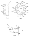
- FIG. 6 shows an example of the burner.
- the burner can have a cone shape, with slots 12 for air entrance and premixing fuel injectors 13 adjacent the slots 12.
- the burners 10 can also have pilot fuel injectors 14 for injecting fuel directly into the combustor 9 (but the pilot fuel injectors 14 are optional); the pilot fuel injected via the pilot fuel injectors 14 undergoes diffusion combustion.
- the pilot fuel injectors 14 can be located around each burner 10, e.g. over a circumference.
- the gas turbine 1 Downstream of the combustion chamber 3 the gas turbine 1 has the turbine 4 that expands the hot gas generated in the combustion chamber to collect mechanical energy, e.g. to activate an electrical generator (not shown).
- Figure 3 shows an example of a combined cycle power plant that further includes a boiler 15 receiving exhaust gas discharged from the turbine 4 to evaporate water and generate superheated steam.
- the superheated steam is expanded in a steam turbine 16 to collect further mechanical energy, e.g. used to activate an electrical generator (the same electrical generator connected to the gas turbine or a different electrical generator).
- the exhaust gas after passing through the boiler 15 are sent to a stack 20 and discharged into the atmosphere.
- the mass flow through the gas turbine is controlled and adjusted via the variable inlet guide vanes 6.
- the air mass flow through the gas turbine is regulated together with the fuel amount supplied into the combustion chamber, such that the gas turbine load is regulated and the combustion occurs efficiently, with limited emissions.
- Adjusting the variable inlet guide vanes 6 causes, in addition to adjusting the mass flow, high stress in the compressor blades downstream of the variable inlet guide vanes 6.
- the stress increases when the opening of the variable inlet guide vanes 6 is reduced (i.e. the amount of air through the gas turbine is reduced).
- the regulation of the variable inlet guide vanes 6 is done only in a limited opening range, e.g. in an opening range between 0 - -20° in order to limit the stress of the compressor blades (0° indicates the reference position with maximum opening and -20° indicates a position closed by 20° with respect to the reference position).
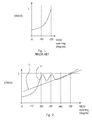
- FIG. 1 shows the relationship between variable inlet guide vanes (VIGV) opening and stress.
- L indicates the stress limit for the compressor blades above which reliable operation is not possible any longer.
- the inventors have found a way to control the load in a broad range (e.g. beyond regulation with variable inlet guide vanes 6) while maintaining the gas turbine operation complying with the emissions requirements and apart from combustion instabilities such as the lean blow off conditions.
- the method comprises (once the fuel amount to be supplied to the combustion chamber is defined on the basis of the load) controlling an oxidizer supply to the combustion chamber and/or a fuel supply to the combustion chamber in order to maintain the flame temperature or a parameter indicative thereof within a given range.
- the given range is a range that allows correct combustion, with limited emissions and reduced risk of flame extinction.
- Controlling the oxidizer supply to the combustion chamber 3 preferably comprises controlling: a variable inlet guide vane opening and/or an oxidizer recirculation to the compressor 2 and/or an oxidizer bypass downstream of the combustion chamber 3.
- controlling the fuel supply to the combustion chamber comprises discontinuing the premixing fuel supply to some burners 10 and increasing the premixing fuel supply to other burners 10.
- burners the operating ones
- these burners operate with a correct fuel/oxidizer ratio, generating a flame with a sufficiently high temperature within the given range, to maintain the emissions within the required values and prevent combustion instabilities such as lean blow off conditions, but the total amount of fuel supplied into the combustion chamber 3 is limited according to the low load conditions.
- the other burners do not operate, i.e. they are not supplied with fuel.
- increasing the premixing fuel supply can be carried out while maintaining substantially constant the total amount of fuel supplied to the gas turbine (because the fuel amount defines the load).
- premixing fuel of circumferentially adjacent burners is increased; this way the blades of the turbine downstream of the combustion chamber 3 are exposed to hot gas having a temperature that is circumferentially substantially uniform.
- the fuel supply to the burners 10IA-10IH can be discontinued, while the fuel supply to the burners 10EA-10EH is increased of the same amount.
- the pilot fuel feed (when provided) is preferably not discontinued when the premixing fuel supply is discontinued.
- the supply of premixing fuel is discontinued while the supply of pilot fuel is not discontinued and the amount of premixing fuel supplied to the burners 10EA-10EH is increased of the same amount as the amount of the premixing fuel discontinued from the burners 10IA-10IH.
- controlling the oxidizer supply to the combustion chamber comprises recirculating a part of the compressed oxidizer from downstream of the compressor 2 to the compressor 2 (i.e. upstream of the compressor or at the compressor, e.g. between the first stage and the last stage of the compressor 2) via the recirculation line 7.
- the amount of flow that passes through the compressor 2 must have a minimum amount, in order to allow safe and reliable operation of the compressor; therefore recirculation of the air allows forwarding to the combustion chamber (and to the turbine) a reduced amount of air while maintaining a correct amount of air through the compressor 2.
- controlling the oxidizer supply to the combustion chamber 3 comprises bypassing a part of the compressed oxidizer from the compressor 2 to downstream of the combustion chamber 3 via the bypass 8.
- the function F indicative of the mechanical stress undergone by compressor blades downstream of the variable inlet guide vanes is indicative of the stress of the blades of the second compressor stage 2b and/or of the third compressor stage 2c; it was ascertained that at these compressor stages the stress is higher.
- the gas turbine is regulated in a load range between 100%-60% of the nominal power by regulating the VIGV opening on the basis of the temperature downstream of the turbine (traditional regulation).
- the gas turbine is regulated in a load range between e.g. 60%-40% of the nominal power by controlling the fuel supplied into the combustion chamber and the discontinuation/increase of the premixing fuel supply to the burners 10 on the basis of the flame temperature (first embodiment described above).
- the gas turbine is regulated in a load range between 100%-60% of the nominal power by regulating the VIGV opening (e.g. in a range 0° - -20°) on the basis of the temperature downstream of the turbine (traditional regulation).
- the gas turbine is further regulated in a load range between e.g. 60%-40% of the nominal power by controlling the fuel supplied into the combustion chamber and the VIGV opening beyond -20° (opening beyond -20° means that the opening is smaller than for a 0° opening; e.g. the control is done in a VIGV opening between -20° - -50°) on the basis of the flame temperature (fourth embodiment described above).
- the gas turbine is regulated in a load range between 100%-60% of the nominal power by regulating the VIGV opening (e.g. in a range 0° - -20°) on the basis of the temperature downstream of the turbine (traditional regulation).
- the gas turbine is further regulated in a load range between e.g. 60%-40% of the nominal power by controlling the fuel supplied into the combustion chamber and the amount of compressed oxidizer that is recirculated (second embodiment above) or is bypassed (third embodiment above) on the basis of the flame temperature.
- control method described above are integrated in order to regulate the gas turbine operation in a broad operating range.
- the gas turbine is regulated in a load range between 100%-60% of the nominal power by regulating the variable inlet guide vane opening (e.g. in a range 0° - -20°) on the basis of the temperature downstream of the turbine (traditional regulation).
- the gas turbine is further regulated in a load range between e.g. 60%-40% by controlling the fuel supplied into the combustion chamber and the variable inlet guide vane opening beyond -20 on the basis of the flame temperature.
- the gas turbine can be further regulated in a load range between e.g. 40%-30% of the nominal power by controlling the fuel supplied into the combustion chamber and the discontinuation/increase of the premixing fuel supply to the burners 10 on the basis of the flame temperature.
- the gas turbine can be further regulated in a load range between 30%-20% by controlling the fuel supplied into the combustion chamber and the amount of compressed oxidizer that is recirculated and/or is bypassed on the basis of the flame temperature.
- gas turbine can be regulated according to any control embodiments or combination of control embodiments described above.
Landscapes
- Engineering & Computer Science (AREA)
- Chemical & Material Sciences (AREA)
- Combustion & Propulsion (AREA)
- Mechanical Engineering (AREA)
- General Engineering & Computer Science (AREA)
- Physics & Mathematics (AREA)
- Fluid Mechanics (AREA)
- Geometry (AREA)
- Control Of Turbines (AREA)
Priority Applications (3)
| Application Number | Priority Date | Filing Date | Title |
|---|---|---|---|
| EP15158140.2A EP3067536A1 (de) | 2015-03-09 | 2015-03-09 | Verfahren zum Betrieb einer Gasturbine |
| US15/065,245 US20160186668A1 (en) | 2015-03-09 | 2016-03-09 | Method for operating a gas turbine |
| CN201610131952.6A CN105952542A (zh) | 2015-03-09 | 2016-03-09 | 用于操作燃气轮机的方法 |
Applications Claiming Priority (1)
| Application Number | Priority Date | Filing Date | Title |
|---|---|---|---|
| EP15158140.2A EP3067536A1 (de) | 2015-03-09 | 2015-03-09 | Verfahren zum Betrieb einer Gasturbine |
Publications (1)
| Publication Number | Publication Date |
|---|---|
| EP3067536A1 true EP3067536A1 (de) | 2016-09-14 |
Family
ID=52627106
Family Applications (1)
| Application Number | Title | Priority Date | Filing Date |
|---|---|---|---|
| EP15158140.2A Withdrawn EP3067536A1 (de) | 2015-03-09 | 2015-03-09 | Verfahren zum Betrieb einer Gasturbine |
Country Status (3)
| Country | Link |
|---|---|
| US (1) | US20160186668A1 (de) |
| EP (1) | EP3067536A1 (de) |
| CN (1) | CN105952542A (de) |
Families Citing this family (4)
| Publication number | Priority date | Publication date | Assignee | Title |
|---|---|---|---|---|
| EP3067530A1 (de) * | 2015-03-09 | 2016-09-14 | General Electric Technology GmbH | Verfahren zum Betrieb einer Gasturbine |
| US10920676B2 (en) | 2016-11-17 | 2021-02-16 | General Electric Company | Low partial load emission control for gas turbine system |
| JP7173897B2 (ja) * | 2019-02-28 | 2022-11-16 | 三菱重工業株式会社 | ガスタービンの運転方法およびガスタービン |
| JP7252861B2 (ja) * | 2019-08-22 | 2023-04-05 | 三菱重工業株式会社 | ガスタービンの燃焼制御装置、燃焼制御方法及びプログラム |
Citations (4)
| Publication number | Priority date | Publication date | Assignee | Title |
|---|---|---|---|---|
| US20030106321A1 (en) * | 2001-12-12 | 2003-06-12 | Von Der Bank Ralf Sebastian | Lean premix burner for a gas turbine and operating method for a lean premix burner |
| US20040011050A1 (en) * | 2000-01-07 | 2004-01-22 | Tsutomu Inoue | Control system for gas-turbine engine |
| US20150059353A1 (en) * | 2013-08-30 | 2015-03-05 | Mitsubishi Hitachi Power Systems, Ltd. | Gas Turbine Combustion System |
| US20150059348A1 (en) * | 2013-08-28 | 2015-03-05 | General Electric Company | System and method for controlling fuel distributions in a combustor in a gas turbine engine |
Family Cites Families (4)
| Publication number | Priority date | Publication date | Assignee | Title |
|---|---|---|---|---|
| US5303542A (en) * | 1992-11-16 | 1994-04-19 | General Electric Company | Fuel supply control method for a gas turbine engine |
| JP4735548B2 (ja) * | 2007-01-17 | 2011-07-27 | 株式会社日立製作所 | 高湿分空気利用ガスタービン及びその運転方法 |
| JP5103454B2 (ja) * | 2009-09-30 | 2012-12-19 | 株式会社日立製作所 | 燃焼器 |
| EP2677239A1 (de) * | 2012-06-19 | 2013-12-25 | Alstom Technology Ltd | Verfahren zum Betrieb einer zwei-stufigen Gasturbinen-Brennkammer |
-
2015
- 2015-03-09 EP EP15158140.2A patent/EP3067536A1/de not_active Withdrawn
-
2016
- 2016-03-09 US US15/065,245 patent/US20160186668A1/en not_active Abandoned
- 2016-03-09 CN CN201610131952.6A patent/CN105952542A/zh active Pending
Patent Citations (4)
| Publication number | Priority date | Publication date | Assignee | Title |
|---|---|---|---|---|
| US20040011050A1 (en) * | 2000-01-07 | 2004-01-22 | Tsutomu Inoue | Control system for gas-turbine engine |
| US20030106321A1 (en) * | 2001-12-12 | 2003-06-12 | Von Der Bank Ralf Sebastian | Lean premix burner for a gas turbine and operating method for a lean premix burner |
| US20150059348A1 (en) * | 2013-08-28 | 2015-03-05 | General Electric Company | System and method for controlling fuel distributions in a combustor in a gas turbine engine |
| US20150059353A1 (en) * | 2013-08-30 | 2015-03-05 | Mitsubishi Hitachi Power Systems, Ltd. | Gas Turbine Combustion System |
Also Published As
| Publication number | Publication date |
|---|---|
| US20160186668A1 (en) | 2016-06-30 |
| CN105952542A (zh) | 2016-09-21 |
Similar Documents
| Publication | Publication Date | Title |
|---|---|---|
| US9752504B2 (en) | Method for operating a gas turbine plant and gas turbine plant for implementing the method | |
| US5634327A (en) | Method of operating a gas-turbine group | |
| CN104981663B (zh) | 操作具有分级和/或连续燃烧的燃气涡轮的方法 | |
| US9708983B2 (en) | Gas turbine with sequential combustion arrangement | |
| US20170058784A1 (en) | System and method for maintaining emissions compliance while operating a gas turbine at turndown condition | |
| EP3135880B1 (de) | Gasturbine mit sequentieller verbrennungsanordnung und brennstoffzusammensetzungssteuerung | |
| US20100281870A1 (en) | System and method for heating fuel for a gas turbine | |
| EP3067536A1 (de) | Verfahren zum Betrieb einer Gasturbine | |
| US20170058770A1 (en) | System and method for decoupling steam production dependency from gas turbine load level | |
| US20160237916A1 (en) | Method of controlling the fuel distribution among different stages of a gas turbine combustion chamber | |
| EP3683426B1 (de) | Verfahren für den betrieb eines gasturbinenkraftwerks und gasturbinenkraftwerk | |
| US20160010566A1 (en) | Method for operating a gas turbine below its rated power | |
| US20170058771A1 (en) | System and method for generating steam during gas turbine low-load conditions | |
| CN104074560A (zh) | 用于燃气轮机联合循环发电机组蒸汽旁路控制的方法 | |
| CN105074170B (zh) | 用于将燃气轮机在其额定功率以下运行的方法 | |
| US20160265443A1 (en) | Method for operating a gas turbine | |
| Teplov et al. | The extension of the operational range of combined-cycle power plant with a triple-pressure heat recovery steam generator | |
| CN109209534B (zh) | 用于启动联合循环发电设备的方法 | |
| EP4261401A1 (de) | Betrieb einer gasturbine mit niedriger last und mel | |
| US20200141323A1 (en) | Method for starting-up and shutting-down a gas turbine in a combined gas and steam power plant |
Legal Events
| Date | Code | Title | Description |
|---|---|---|---|
| PUAI | Public reference made under article 153(3) epc to a published international application that has entered the european phase |
Free format text: ORIGINAL CODE: 0009012 |
|
| AK | Designated contracting states |
Kind code of ref document: A1 Designated state(s): AL AT BE BG CH CY CZ DE DK EE ES FI FR GB GR HR HU IE IS IT LI LT LU LV MC MK MT NL NO PL PT RO RS SE SI SK SM TR |
|
| AX | Request for extension of the european patent |
Extension state: BA ME |
|
| 17P | Request for examination filed |
Effective date: 20170313 |
|
| RBV | Designated contracting states (corrected) |
Designated state(s): AL AT BE BG CH CY CZ DE DK EE ES FI FR GB GR HR HU IE IS IT LI LT LU LV MC MK MT NL NO PL PT RO RS SE SI SK SM TR |
|
| RAP1 | Party data changed (applicant data changed or rights of an application transferred) |
Owner name: ANSALDO ENERGIA IP UK LIMITED |
|
| STAA | Information on the status of an ep patent application or granted ep patent |
Free format text: STATUS: THE APPLICATION IS DEEMED TO BE WITHDRAWN |
|
| 18D | Application deemed to be withdrawn |
Effective date: 20181002 |