EP3067576A1 - Rotule, en particulier une rotule pour une bielle, et bielle munie de cette rotule - Google Patents
Rotule, en particulier une rotule pour une bielle, et bielle munie de cette rotule Download PDFInfo
- Publication number
- EP3067576A1 EP3067576A1 EP16152498.8A EP16152498A EP3067576A1 EP 3067576 A1 EP3067576 A1 EP 3067576A1 EP 16152498 A EP16152498 A EP 16152498A EP 3067576 A1 EP3067576 A1 EP 3067576A1
- Authority
- EP
- European Patent Office
- Prior art keywords
- ball head
- ball
- connecting rod
- ball bearing
- head receptacle
- Prior art date
- Legal status (The legal status is an assumption and is not a legal conclusion. Google has not performed a legal analysis and makes no representation as to the accuracy of the status listed.)
- Withdrawn
Links
- 238000002485 combustion reaction Methods 0.000 claims description 12
- 230000006835 compression Effects 0.000 claims description 12
- 238000007906 compression Methods 0.000 claims description 12
- 230000002349 favourable effect Effects 0.000 description 9
- 238000004519 manufacturing process Methods 0.000 description 4
- 239000002184 metal Substances 0.000 description 4
- 238000005299 abrasion Methods 0.000 description 2
- 230000008092 positive effect Effects 0.000 description 1
- 230000036316 preload Effects 0.000 description 1
Images


Classifications
-
- F—MECHANICAL ENGINEERING; LIGHTING; HEATING; WEAPONS; BLASTING
- F02—COMBUSTION ENGINES; HOT-GAS OR COMBUSTION-PRODUCT ENGINE PLANTS
- F02D—CONTROLLING COMBUSTION ENGINES
- F02D15/00—Varying compression ratio
- F02D15/02—Varying compression ratio by alteration or displacement of piston stroke
-
- F—MECHANICAL ENGINEERING; LIGHTING; HEATING; WEAPONS; BLASTING
- F16—ENGINEERING ELEMENTS AND UNITS; GENERAL MEASURES FOR PRODUCING AND MAINTAINING EFFECTIVE FUNCTIONING OF MACHINES OR INSTALLATIONS; THERMAL INSULATION IN GENERAL
- F16C—SHAFTS; FLEXIBLE SHAFTS; ELEMENTS OR CRANKSHAFT MECHANISMS; ROTARY BODIES OTHER THAN GEARING ELEMENTS; BEARINGS
- F16C9/00—Bearings for crankshafts or connecting-rods; Attachment of connecting-rods
- F16C9/04—Connecting-rod bearings; Attachments thereof
-
- F—MECHANICAL ENGINEERING; LIGHTING; HEATING; WEAPONS; BLASTING
- F02—COMBUSTION ENGINES; HOT-GAS OR COMBUSTION-PRODUCT ENGINE PLANTS
- F02B—INTERNAL-COMBUSTION PISTON ENGINES; COMBUSTION ENGINES IN GENERAL
- F02B75/00—Other engines
- F02B75/04—Engines with variable distances between pistons at top dead-centre positions and cylinder heads
- F02B75/045—Engines with variable distances between pistons at top dead-centre positions and cylinder heads by means of a variable connecting rod length
-
- F—MECHANICAL ENGINEERING; LIGHTING; HEATING; WEAPONS; BLASTING
- F16—ENGINEERING ELEMENTS AND UNITS; GENERAL MEASURES FOR PRODUCING AND MAINTAINING EFFECTIVE FUNCTIONING OF MACHINES OR INSTALLATIONS; THERMAL INSULATION IN GENERAL
- F16C—SHAFTS; FLEXIBLE SHAFTS; ELEMENTS OR CRANKSHAFT MECHANISMS; ROTARY BODIES OTHER THAN GEARING ELEMENTS; BEARINGS
- F16C11/00—Pivots; Pivotal connections
- F16C11/04—Pivotal connections
- F16C11/06—Ball-joints; Other joints having more than one degree of angular freedom, i.e. universal joints
- F16C11/0619—Ball-joints; Other joints having more than one degree of angular freedom, i.e. universal joints the female part comprising a blind socket receiving the male part
-
- F—MECHANICAL ENGINEERING; LIGHTING; HEATING; WEAPONS; BLASTING
- F16—ENGINEERING ELEMENTS AND UNITS; GENERAL MEASURES FOR PRODUCING AND MAINTAINING EFFECTIVE FUNCTIONING OF MACHINES OR INSTALLATIONS; THERMAL INSULATION IN GENERAL
- F16C—SHAFTS; FLEXIBLE SHAFTS; ELEMENTS OR CRANKSHAFT MECHANISMS; ROTARY BODIES OTHER THAN GEARING ELEMENTS; BEARINGS
- F16C11/00—Pivots; Pivotal connections
- F16C11/04—Pivotal connections
- F16C11/06—Ball-joints; Other joints having more than one degree of angular freedom, i.e. universal joints
- F16C11/0619—Ball-joints; Other joints having more than one degree of angular freedom, i.e. universal joints the female part comprising a blind socket receiving the male part
- F16C11/0623—Construction or details of the socket member
-
- F—MECHANICAL ENGINEERING; LIGHTING; HEATING; WEAPONS; BLASTING
- F16—ENGINEERING ELEMENTS AND UNITS; GENERAL MEASURES FOR PRODUCING AND MAINTAINING EFFECTIVE FUNCTIONING OF MACHINES OR INSTALLATIONS; THERMAL INSULATION IN GENERAL
- F16C—SHAFTS; FLEXIBLE SHAFTS; ELEMENTS OR CRANKSHAFT MECHANISMS; ROTARY BODIES OTHER THAN GEARING ELEMENTS; BEARINGS
- F16C11/00—Pivots; Pivotal connections
- F16C11/04—Pivotal connections
- F16C11/06—Ball-joints; Other joints having more than one degree of angular freedom, i.e. universal joints
- F16C11/0685—Manufacture of ball-joints and parts thereof, e.g. assembly of ball-joints
- F16C11/069—Manufacture of ball-joints and parts thereof, e.g. assembly of ball-joints with at least one separate part to retain the ball member in the socket; Quick-release systems
-
- F—MECHANICAL ENGINEERING; LIGHTING; HEATING; WEAPONS; BLASTING
- F16—ENGINEERING ELEMENTS AND UNITS; GENERAL MEASURES FOR PRODUCING AND MAINTAINING EFFECTIVE FUNCTIONING OF MACHINES OR INSTALLATIONS; THERMAL INSULATION IN GENERAL
- F16C—SHAFTS; FLEXIBLE SHAFTS; ELEMENTS OR CRANKSHAFT MECHANISMS; ROTARY BODIES OTHER THAN GEARING ELEMENTS; BEARINGS
- F16C11/00—Pivots; Pivotal connections
- F16C11/04—Pivotal connections
- F16C11/10—Arrangements for locking
- F16C11/103—Arrangements for locking frictionally clamped
- F16C11/106—Arrangements for locking frictionally clamped for ball joints
-
- F—MECHANICAL ENGINEERING; LIGHTING; HEATING; WEAPONS; BLASTING
- F16—ENGINEERING ELEMENTS AND UNITS; GENERAL MEASURES FOR PRODUCING AND MAINTAINING EFFECTIVE FUNCTIONING OF MACHINES OR INSTALLATIONS; THERMAL INSULATION IN GENERAL
- F16C—SHAFTS; FLEXIBLE SHAFTS; ELEMENTS OR CRANKSHAFT MECHANISMS; ROTARY BODIES OTHER THAN GEARING ELEMENTS; BEARINGS
- F16C7/00—Connecting-rods or like links pivoted at both ends; Construction of connecting-rod heads
- F16C7/06—Adjustable connecting-rods
-
- F—MECHANICAL ENGINEERING; LIGHTING; HEATING; WEAPONS; BLASTING
- F16—ENGINEERING ELEMENTS AND UNITS; GENERAL MEASURES FOR PRODUCING AND MAINTAINING EFFECTIVE FUNCTIONING OF MACHINES OR INSTALLATIONS; THERMAL INSULATION IN GENERAL
- F16J—PISTONS; CYLINDERS; SEALINGS
- F16J1/00—Pistons; Trunk pistons; Plungers
- F16J1/10—Connection to driving members
- F16J1/12—Connection to driving members with piston-rods, e.g. rigid connections
-
- F—MECHANICAL ENGINEERING; LIGHTING; HEATING; WEAPONS; BLASTING
- F16—ENGINEERING ELEMENTS AND UNITS; GENERAL MEASURES FOR PRODUCING AND MAINTAINING EFFECTIVE FUNCTIONING OF MACHINES OR INSTALLATIONS; THERMAL INSULATION IN GENERAL
- F16J—PISTONS; CYLINDERS; SEALINGS
- F16J1/00—Pistons; Trunk pistons; Plungers
- F16J1/10—Connection to driving members
- F16J1/14—Connection to driving members with connecting-rods, i.e. pivotal connections
- F16J1/22—Connection to driving members with connecting-rods, i.e. pivotal connections with universal joint, e.g. ball-joint
-
- F—MECHANICAL ENGINEERING; LIGHTING; HEATING; WEAPONS; BLASTING
- F16—ENGINEERING ELEMENTS AND UNITS; GENERAL MEASURES FOR PRODUCING AND MAINTAINING EFFECTIVE FUNCTIONING OF MACHINES OR INSTALLATIONS; THERMAL INSULATION IN GENERAL
- F16J—PISTONS; CYLINDERS; SEALINGS
- F16J7/00—Piston-rods
-
- F—MECHANICAL ENGINEERING; LIGHTING; HEATING; WEAPONS; BLASTING
- F16—ENGINEERING ELEMENTS AND UNITS; GENERAL MEASURES FOR PRODUCING AND MAINTAINING EFFECTIVE FUNCTIONING OF MACHINES OR INSTALLATIONS; THERMAL INSULATION IN GENERAL
- F16C—SHAFTS; FLEXIBLE SHAFTS; ELEMENTS OR CRANKSHAFT MECHANISMS; ROTARY BODIES OTHER THAN GEARING ELEMENTS; BEARINGS
- F16C23/00—Bearings for exclusively rotary movement adjustable for aligning or positioning
- F16C23/10—Bearings, parts of which are eccentrically adjustable with respect to each other
-
- F—MECHANICAL ENGINEERING; LIGHTING; HEATING; WEAPONS; BLASTING
- F16—ENGINEERING ELEMENTS AND UNITS; GENERAL MEASURES FOR PRODUCING AND MAINTAINING EFFECTIVE FUNCTIONING OF MACHINES OR INSTALLATIONS; THERMAL INSULATION IN GENERAL
- F16C—SHAFTS; FLEXIBLE SHAFTS; ELEMENTS OR CRANKSHAFT MECHANISMS; ROTARY BODIES OTHER THAN GEARING ELEMENTS; BEARINGS
- F16C2360/00—Engines or pumps
- F16C2360/22—Internal combustion engines
Definitions
- the invention relates to a ball bearing and a connecting rod with a ball bearing.
- a high compression ratio has a positive effect on the efficiency of the internal combustion engine.
- compression ratio is generally understood the ratio of the entire cylinder space before compression to the remaining cylinder space after compression.
- the compression ratio may only be selected so high that a so-called "knocking" of the internal combustion engine is avoided at full load operation.
- the compression ratio could be selected with higher values without "knocking" occurring.
- the important part load range of an internal combustion engine can be improved if the compression ratio is variably adjustable. For the adjustment of the compression ratio, for example, systems with variable connecting rod length are known.
- a connecting rod in which a pivotable lever is inserted in the small connecting rod eye, in whose central opening an eccentric is inserted.
- the eccentric serves to receive a piston pin.
- the lever forms a shaft-hub connection with the eccentric. Since the connection is heavily loaded during operation of the connecting rod, the demands on the manufacturing tolerances of the connection partners are high.
- the support rods, which are mounted on the upper connecting rod eye, are mounted in a spherical bearing in a ball bearing and screwed there with cross bolts.
- An object of the invention is to provide a heavy-duty ball bearing with a ball head mounted in a ball bearing, which is easy to assemble and is highly resilient and allows manufacturing tolerances.
- Another object is to provide a connecting rod with such a ball bearing.
- the locking ring can be easily inserted into the ball head receptacle.
- the securing ring may be formed symmetrically, in particular along its longitudinal axis, so that a mounting can be carried out confusion.
- the embodiment may also be asymmetrical.
- the ball head is pivotable in the ball head receptacle and at the same time axially pulled out only with high pull-out force from the ball head receptacle.
- the retaining ring may be placed with bias against a wall of the ball head socket. Due to the radial preload an axial securing of the ball head is already possible.
- the ball head receptacle may have an undercut at its open end, which secures the circlip axially in the ball head receptacle.
- Such an undercut is easily produced in terms of production and offers a particularly high level of safety against sliding out of the securing ring and thus of the ball head from the ball head receptacle.
- the ball head receptacle may have a curved bottom part, to which a cylindrical space adjoins in the axial direction.
- the curved bottom part is advantageously adapted in the contact area to the outer contour of the ball head, so that the ball head is easily pivoted.
- the curved bottom part offers a defined end position of the ball head in the axial direction.
- the arched area is advantageously about as deep as the radius of the ball head.
- the cylindrical space provides space for receiving the locking ring and is larger in diameter than the ball head.
- the retaining ring may be interrupted at its periphery.
- the circlip can be reduced for mounting with a suitable tool in the scope and introduced into the ball head receptacle and then expand again in the scope and bear against the wall of the ball head receiving radially biased.
- the inner diameter of the ball head receptacle in the intended contact area with the retaining ring and the outer diameter of the locking ring can be suitably matched to one another.
- the securing ring may have a radially inwardly facing collar at its in the installed state the ball head facing end face. This may be a flanged edge, or one or more inwardly folded wall parts of the locking ring.
- the retaining ring may be, for example, a bent sheet metal part.
- the retaining ring may have a curvature radially inward.
- this curvature be formed symmetrically to a center of a longitudinal axis of the securing ring. This allows a particularly low-abrasion contact between circlip and ball head, so that even higher purity requirements can be met.
- the retaining ring may be formed of plastic.
- the ball head may advantageously be made of metal.
- the pairing metal / plastic is particularly favorable to avoid abrasion.
- a connecting rod with at least one ball bearing is proposed with a arranged on a support rod ball head, wherein the ball head is mounted in a ball head receptacle, and wherein the ball head secured on its outer surface in the ball head receptacle by a locking ring against slipping out of the ball head is.
- the ball bearing is inexpensive to manufacture, easy to assemble and offers a high pull-out force against pulling out of the ball head from the ball head.
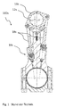
- the well-known connecting rod 100s in FIG. 1 has an upper Pleuellagerauge 12s, which is provided for receiving a piston pin, not shown. This piston pin is firmly inserted in a conventional manner in a combustion chamber piston of the internal combustion engine.
- the upper Pleuellagerauge 12s is separated by a connecting rod of the bottom in the figure, large connecting rod eye.
- the upper Pleuellagerauge 12s is pivotable about a pivot axis by means of a designed as an eccentric bearing member, which is offset parallel to the longitudinal axis of the upper Pleuellagerauges 12s.
- the eccentric is inserted into an opening of a lever 16s.
- the actuating piston 18s are mounted with a ball bearing 10s in recordings and screwed there with cross bolt.
- the adjusting pistons 18s are acted on by a hydraulic pressure prevailing in the hydraulic chambers interacting with the adjusting pistons 18s.
- FIG. 2 shows a first embodiment of a ball bearing 10 according to an embodiment of the invention.
- the ball bearing 10 comprises a ball head 20, which is arranged on a support rod 18 and which is mounted in a ball head receptacle 30 of an outer part 40.
- the ball head 20 is on its outer surface in the Ball head 30 secured by a locking ring 50 against sliding out of the ball head receptacle 30.
- the ball head receptacle 30 comprises a curved bottom part 32, which is adapted to the outer contour of the ball head 20 and on which the ball head 20 can slide in order to allow tilting of the support bar 18.
- a cylindrical space 34 adjoins, in which the securing ring 50 is arranged.
- the ball head receptacle 30 has at its open end an undercut 36, which secures the circlip 50 axially in the ball head receptacle 30. This is a high security against sliding out or pulling out of the locking ring 50 and thus the ball head 20 from the ball head receptacle 30 given.
- the circlip 50 bears with bias against a wall 38 of the ball head receptacle 30.
- the circlip 50 is slotted and can be compressed for assembly and inserted into the ball head receptacle 30.
- the slotted circlip 50 can easily slide over the support rod 18.
- the snap ring 50 is e.g. formed as a sheet metal component and has at its in the installed state the ball head 20 facing end side on a radially inwardly facing collar 52, which limits an axial movement of the ball head 20. At the same time, the ball head can slide with its outer surface on the collar 52 at a tilt.
- FIG. 3 shows a further embodiment of a ball bearing 10 according to an embodiment of the invention.
- the ball bearing 10 comprises a ball head 20, which is arranged on a support rod 18 and which is mounted in a ball head receptacle 30 of an outer part 40.
- the ball head 20 is secured on its outer surface in the ball head receptacle 30 by a securing ring 50 against sliding out of the ball head receptacle 30.
- the ball head receptacle 30 comprises a curved bottom part 32, which is adapted to the outer contour of the ball head 20 and on which the ball head 20 can slide in order to allow tilting of the support bar 18.
- a cylindrical space 34 adjoins, in which the securing ring 50 is arranged.
- the ball head receptacle 30 has at its open end an undercut 36, which secures the circlip 50 axially in the ball head receptacle 30. This is a high security against sliding out or pulling out of the locking ring 50 and thus the ball head 20 from the ball head receptacle 30 given.
- the circlip 50 settles with bias against a wall 38 of the ball head receptacle 30.
- the circlip 50 is slotted and can be compressed for assembly and inserted into the ball head receptacle 30.
- the slotted circlip 50 can easily slide over the support rod 18.
- the snap ring 50 is e.g. formed from plastic and has at its in the installed state the ball head 20 facing end face a radially inwardly facing camber 54, which limits an axial movement of the ball head 20. At the same time, the ball head can slide with its outer surface on the bulge 54 at a tilt.
- the ball bearing 10 is advantageously used for the storage of the support rod 18 of a connecting rod 100, which is used for example in an internal combustion engine with adjustable compression ratio, wherein the connecting rod 100 as described above may comprise means for adjusting the effective connecting rod length. Even at high load, the ball head 20 of the ball bearing 10 is securely held in the ball head receptacle 30.
Landscapes
- Engineering & Computer Science (AREA)
- General Engineering & Computer Science (AREA)
- Mechanical Engineering (AREA)
- Chemical & Material Sciences (AREA)
- Combustion & Propulsion (AREA)
- Shafts, Cranks, Connecting Bars, And Related Bearings (AREA)
Applications Claiming Priority (1)
| Application Number | Priority Date | Filing Date | Title |
|---|---|---|---|
| DE102015103463.8A DE102015103463A1 (de) | 2015-03-10 | 2015-03-10 | Kugellager, insbesondere Pleuelkugellager, sowie Pleuel mit einem Kugellager |
Publications (1)
| Publication Number | Publication Date |
|---|---|
| EP3067576A1 true EP3067576A1 (fr) | 2016-09-14 |
Family
ID=55262693
Family Applications (1)
| Application Number | Title | Priority Date | Filing Date |
|---|---|---|---|
| EP16152498.8A Withdrawn EP3067576A1 (fr) | 2015-03-10 | 2016-01-25 | Rotule, en particulier une rotule pour une bielle, et bielle munie de cette rotule |
Country Status (4)
| Country | Link |
|---|---|
| US (1) | US10018124B2 (fr) |
| EP (1) | EP3067576A1 (fr) |
| CN (1) | CN105972058A (fr) |
| DE (1) | DE102015103463A1 (fr) |
Cited By (3)
| Publication number | Priority date | Publication date | Assignee | Title |
|---|---|---|---|---|
| DE102017116122B3 (de) | 2017-07-18 | 2018-08-23 | Dr. Ing. H.C. F. Porsche Aktiengesellschaft | Verfahren zum Herstellen einer Einheit aus Exzenterstange und Kolben einer Pleuelstange eines Verbrennungsmotors |
| DE102017117028A1 (de) | 2017-07-27 | 2019-01-31 | Dr. Ing. H.C. F. Porsche Aktiengesellschaft | Pleuelstange und Verbrennungsmotor |
| WO2020227749A1 (fr) * | 2019-05-15 | 2020-11-19 | Iwis Motorsysteme Gmbh & Co. Kg | Bielle à liaison par complémentarité de forme |
Families Citing this family (15)
| Publication number | Priority date | Publication date | Assignee | Title |
|---|---|---|---|---|
| DE102017113250A1 (de) * | 2016-12-21 | 2018-06-21 | ECO Holding 1 GmbH | Kolben für eine Pleuelstange und Pleuelstange |
| DE102017108982B4 (de) | 2017-04-26 | 2024-02-15 | Benteler Automobiltechnik Gmbh | Radlenker mit einem Kugelgelenk |
| DE202017007697U1 (de) | 2017-04-28 | 2024-07-15 | ECO Holding 1 GmbH | Pleuel mit einem Kugelgelenk |
| DE102017109172A1 (de) | 2017-04-28 | 2018-10-31 | ECO Holding 1 GmbH | Pleuel mit einem Kugelgelenk sowie Verfahren zur Herstellung einer Kugelgelenkverbindung |
| DE102018103387A1 (de) | 2017-06-23 | 2018-12-27 | ECO Holding 1 GmbH | Pleuel für eine Brennkraftmaschine mit variabler Verdichtung |
| EP3418533B1 (fr) | 2017-06-23 | 2020-04-22 | ECO Holding 1 GmbH | Bielle pour un moteur à combustion interne à compression variable |
| CN109931159A (zh) * | 2017-12-19 | 2019-06-25 | 伊希欧1控股有限公司 | 内燃机的具有调整有效连杆长度的偏心轮调整装置的连杆 |
| DE102018107059A1 (de) | 2017-12-20 | 2019-06-27 | ECO Holding 1 GmbH | Pleuel für eine Brennkraftmaschine mit variabler Verdichtung |
| CN108266453A (zh) * | 2018-03-19 | 2018-07-10 | 江苏可奈力机械制造有限公司 | 一种新型连杆柱塞结构 |
| DE102018115727B3 (de) * | 2018-06-29 | 2019-11-07 | Dr. Ing. H.C. F. Porsche Aktiengesellschaft | Abstützanordnung für ein Exzenterorgan einer Verstellanordnung sowie Verstellanordnung |
| DE102018131049A1 (de) | 2018-12-05 | 2020-06-10 | ECO Holding 1 GmbH | Kugelgelenk sowie Pleuel mit einem Kugelgelenk |
| DE102019117463A1 (de) * | 2019-06-28 | 2020-06-10 | ECO Holding 1 GmbH | Pleuel für eine Brennkraftmaschine mit variabler Verdichtung und Verfahren zur Herstellung eines Pleuels |
| DE102019119187A1 (de) | 2019-07-16 | 2020-07-23 | ECO Holding 1 GmbH | Pleuel für eine Brennkraftmaschine mit variabler Verdichtung |
| DE102021002183B4 (de) | 2021-04-24 | 2023-06-07 | Jan Grinbaum | Kugelgelenk und Verfahren für seine Herstellung |
| WO2025258261A1 (fr) * | 2024-06-14 | 2025-12-18 | ヒーハイスト株式会社 | Palier sphérique |
Citations (18)
| Publication number | Priority date | Publication date | Assignee | Title |
|---|---|---|---|---|
| DE659600C (de) * | 1936-05-24 | 1938-05-09 | Fritz Faudi | Kugelgelenk |
| US2856250A (en) * | 1957-02-13 | 1958-10-14 | Thoma Hans Johannes | Pistons and piston rods |
| US2894548A (en) * | 1956-01-09 | 1959-07-14 | Peck Rudolph | Clamp with interchangeable pressure pad |
| GB900320A (en) * | 1959-03-06 | 1962-07-04 | Wilton Tool Mfg Co Inc | Improvements in clamps or the like for holding work pieces |
| DE2757198A1 (de) * | 1977-12-22 | 1979-06-28 | Ehrenreich Gmbh & Co Kg A | Kugelgelenk |
| DE2934218A1 (de) * | 1979-08-24 | 1981-03-19 | Alfred Teves Gmbh, 6000 Frankfurt | Gelenkverbindung |
| US4601603A (en) * | 1984-08-13 | 1986-07-22 | Nifco Inc. | Ball joint |
| US4666330A (en) * | 1985-12-04 | 1987-05-19 | Tuthill Corporation | Ball joint assembly |
| DE3607149A1 (de) * | 1986-03-05 | 1987-09-10 | Bosch Gmbh Robert | Kugelgelenk |
| US5153976A (en) * | 1992-03-23 | 1992-10-13 | Allied-Signal Inc. | Ball-and-socket assembly and method of making |
| US5247873A (en) * | 1992-01-28 | 1993-09-28 | Cooper Industries, Inc. | Connecting rod assembly with a crosshead |
| DE29702140U1 (de) * | 1997-02-08 | 1997-04-03 | Demmeler Maschinenbau GmbH, 87751 Heimertingen | Spannwerkzeug |
| DE29713483U1 (de) * | 1997-07-29 | 1998-01-08 | Kleinbongartz & Kaiser Werkzeugfabrik, 42853 Remscheid | Schraubzwinge |
| DE19752076A1 (de) * | 1997-11-25 | 1999-05-27 | Schaeffler Waelzlager Ohg | Anbindung einer Kolbenstange am Kolben eines Geberzylinders |
| WO2006110133A1 (fr) * | 2005-04-08 | 2006-10-19 | Federal-Mogul Corporation | Articulation a rotule avec paliers metalliques coupes pour charges de compression |
| DE102005055199A1 (de) | 2005-11-19 | 2007-05-24 | Fev Motorentechnik Gmbh | Hubkolbenverbrennungskraftmaschine mit einstellbar veränderbarem Verdichtungsverhältnis |
| WO2012095203A1 (fr) * | 2011-01-12 | 2012-07-19 | Schaeffler Technologies AG & Co. KG | Articulation oscillante |
| DE102013224270B3 (de) * | 2013-11-27 | 2015-01-08 | Schaeffler Technologies Gmbh & Co. Kg | Vorrichtung zur Veränderung des Verdichtungsverhältnisses einer Zylindereinheit einer Hubkolbenbrennkraftmaschine |
Family Cites Families (8)
| Publication number | Priority date | Publication date | Assignee | Title |
|---|---|---|---|---|
| US3107505A (en) * | 1961-02-15 | 1963-10-22 | Hague Mfg Company | Universal joint |
| DE3607150A1 (de) * | 1986-03-05 | 1987-09-10 | Bosch Gmbh Robert | Kugelgelenk |
| EP1617472A1 (fr) | 2004-07-16 | 2006-01-18 | Axalto SA | Dispositif de protection actif pour la protection d'un circuit contre une attaque mecanique et électromagnétique |
| DE102006052254B4 (de) * | 2006-11-03 | 2012-12-20 | Zf Friedrichshafen Ag | Kugelgelenk |
| DE102008048515A1 (de) * | 2008-09-23 | 2010-03-25 | Schaeffler Kg | Winkelgelenk |
| US8511265B2 (en) * | 2009-06-01 | 2013-08-20 | Steven Don Arnold | Variable stroke and compression ratio engine |
| WO2012133643A1 (fr) * | 2011-03-31 | 2012-10-04 | 武蔵精密工業株式会社 | Procédé de fabrication d'un joint à rotule |
| CN104937238B (zh) * | 2012-12-21 | 2017-11-07 | 博格华纳公司 | 可变压缩比活塞系统 |
-
2015
- 2015-03-10 DE DE102015103463.8A patent/DE102015103463A1/de not_active Withdrawn
- 2015-12-30 US US14/984,923 patent/US10018124B2/en not_active Expired - Fee Related
-
2016
- 2016-01-25 EP EP16152498.8A patent/EP3067576A1/fr not_active Withdrawn
- 2016-02-03 CN CN201610076101.6A patent/CN105972058A/zh active Pending
Patent Citations (18)
| Publication number | Priority date | Publication date | Assignee | Title |
|---|---|---|---|---|
| DE659600C (de) * | 1936-05-24 | 1938-05-09 | Fritz Faudi | Kugelgelenk |
| US2894548A (en) * | 1956-01-09 | 1959-07-14 | Peck Rudolph | Clamp with interchangeable pressure pad |
| US2856250A (en) * | 1957-02-13 | 1958-10-14 | Thoma Hans Johannes | Pistons and piston rods |
| GB900320A (en) * | 1959-03-06 | 1962-07-04 | Wilton Tool Mfg Co Inc | Improvements in clamps or the like for holding work pieces |
| DE2757198A1 (de) * | 1977-12-22 | 1979-06-28 | Ehrenreich Gmbh & Co Kg A | Kugelgelenk |
| DE2934218A1 (de) * | 1979-08-24 | 1981-03-19 | Alfred Teves Gmbh, 6000 Frankfurt | Gelenkverbindung |
| US4601603A (en) * | 1984-08-13 | 1986-07-22 | Nifco Inc. | Ball joint |
| US4666330A (en) * | 1985-12-04 | 1987-05-19 | Tuthill Corporation | Ball joint assembly |
| DE3607149A1 (de) * | 1986-03-05 | 1987-09-10 | Bosch Gmbh Robert | Kugelgelenk |
| US5247873A (en) * | 1992-01-28 | 1993-09-28 | Cooper Industries, Inc. | Connecting rod assembly with a crosshead |
| US5153976A (en) * | 1992-03-23 | 1992-10-13 | Allied-Signal Inc. | Ball-and-socket assembly and method of making |
| DE29702140U1 (de) * | 1997-02-08 | 1997-04-03 | Demmeler Maschinenbau GmbH, 87751 Heimertingen | Spannwerkzeug |
| DE29713483U1 (de) * | 1997-07-29 | 1998-01-08 | Kleinbongartz & Kaiser Werkzeugfabrik, 42853 Remscheid | Schraubzwinge |
| DE19752076A1 (de) * | 1997-11-25 | 1999-05-27 | Schaeffler Waelzlager Ohg | Anbindung einer Kolbenstange am Kolben eines Geberzylinders |
| WO2006110133A1 (fr) * | 2005-04-08 | 2006-10-19 | Federal-Mogul Corporation | Articulation a rotule avec paliers metalliques coupes pour charges de compression |
| DE102005055199A1 (de) | 2005-11-19 | 2007-05-24 | Fev Motorentechnik Gmbh | Hubkolbenverbrennungskraftmaschine mit einstellbar veränderbarem Verdichtungsverhältnis |
| WO2012095203A1 (fr) * | 2011-01-12 | 2012-07-19 | Schaeffler Technologies AG & Co. KG | Articulation oscillante |
| DE102013224270B3 (de) * | 2013-11-27 | 2015-01-08 | Schaeffler Technologies Gmbh & Co. Kg | Vorrichtung zur Veränderung des Verdichtungsverhältnisses einer Zylindereinheit einer Hubkolbenbrennkraftmaschine |
Cited By (5)
| Publication number | Priority date | Publication date | Assignee | Title |
|---|---|---|---|---|
| DE102017116122B3 (de) | 2017-07-18 | 2018-08-23 | Dr. Ing. H.C. F. Porsche Aktiengesellschaft | Verfahren zum Herstellen einer Einheit aus Exzenterstange und Kolben einer Pleuelstange eines Verbrennungsmotors |
| US10557408B2 (en) | 2017-07-18 | 2020-02-11 | Dr. Ing. H.C. F. Porsche Aktiengesellschaft | Method for producing a unit consisting of eccentric rod and piston of a connecting rod of an internal combustion engine |
| DE102017117028A1 (de) | 2017-07-27 | 2019-01-31 | Dr. Ing. H.C. F. Porsche Aktiengesellschaft | Pleuelstange und Verbrennungsmotor |
| DE102017117028B4 (de) * | 2017-07-27 | 2021-06-10 | Dr. Ing. H.C. F. Porsche Aktiengesellschaft | Pleuelstange mit Exzenter-Verstelleinrichtung und Verbrennungsmotor |
| WO2020227749A1 (fr) * | 2019-05-15 | 2020-11-19 | Iwis Motorsysteme Gmbh & Co. Kg | Bielle à liaison par complémentarité de forme |
Also Published As
| Publication number | Publication date |
|---|---|
| US10018124B2 (en) | 2018-07-10 |
| DE102015103463A1 (de) | 2016-09-15 |
| CN105972058A (zh) | 2016-09-28 |
| US20160265448A1 (en) | 2016-09-15 |
Similar Documents
| Publication | Publication Date | Title |
|---|---|---|
| DE102015103463A1 (de) | Kugellager, insbesondere Pleuelkugellager, sowie Pleuel mit einem Kugellager | |
| DE102013014090A1 (de) | Verbrennungsmotor und Pleuelstange | |
| DE102010005606A1 (de) | Nockenfolger zur Betätigung eines Gaswechselventils | |
| DE102015109924A1 (de) | Kolben für eine Pleuelstange und Pleuelstange | |
| EP1716355B1 (fr) | Palier d'axe pour piston d'un moteur a combustion interne | |
| DE102014218961A1 (de) | Rollenstößel und Verfahren zum Herstellen eines Gehäuseelements eines Rollenstößels | |
| EP1347172A2 (fr) | Pompe à piston | |
| DE102015103207A1 (de) | Pleuelstange und Verbrennungsmotor | |
| EP3268641B1 (fr) | Bielle comprenant une articulation à rotule | |
| DE102015103202A1 (de) | Pleuelstange und Verbrennungsmotor | |
| DE102015109580A1 (de) | Einleger und Pleuel für eine variable Verdichtung einer Brennkraftmaschine | |
| DE102016208907A1 (de) | Bogenförmige Anlaufscheibe für ein Zylinderkurbelgehäuse einer Hubkolben-Brennkraftmaschine | |
| WO2021068018A1 (fr) | Bielle à longueur réglable comprenant un dispositif d'étanchéité | |
| EP1920174B1 (fr) | Geometrie d'alesage d'axe de piston continue destinee a un piston d'un moteur a combustion interne | |
| DE102017113250A1 (de) | Kolben für eine Pleuelstange und Pleuelstange | |
| DE102019119854A1 (de) | Pleuel für eine Brennkraftmaschine mit variabler Verdichtung | |
| DE102005037205A1 (de) | Zweiteiliger Ölabstreifring für Verbrennungsmotoren | |
| DE102009018981A1 (de) | Kolben für eine Hubkolbenmaschine | |
| WO2017157649A1 (fr) | Articulation sphérique et bielle avec une articulation sphérique | |
| EP3339602B1 (fr) | Bielle pour un moteur à combustion interne à compression variable | |
| WO2015040126A1 (fr) | Piston puni d'une gorge de segment de piston, en particulier d'une gorge de compression | |
| EP3274574B1 (fr) | Bielle avec liaison arbre-moyeu | |
| DE102019117463A1 (de) | Pleuel für eine Brennkraftmaschine mit variabler Verdichtung und Verfahren zur Herstellung eines Pleuels | |
| DE102018203417A1 (de) | Kolbenanordnung einer Brennkraftmaschine | |
| EP3642513B1 (fr) | Segment de piston racleur d'huile |
Legal Events
| Date | Code | Title | Description |
|---|---|---|---|
| PUAI | Public reference made under article 153(3) epc to a published international application that has entered the european phase |
Free format text: ORIGINAL CODE: 0009012 |
|
| AK | Designated contracting states |
Kind code of ref document: A1 Designated state(s): AL AT BE BG CH CY CZ DE DK EE ES FI FR GB GR HR HU IE IS IT LI LT LU LV MC MK MT NL NO PL PT RO RS SE SI SK SM TR |
|
| AX | Request for extension of the european patent |
Extension state: BA ME |
|
| 17P | Request for examination filed |
Effective date: 20160926 |
|
| RBV | Designated contracting states (corrected) |
Designated state(s): AL AT BE BG CH CY CZ DE DK EE ES FI FR GB GR HR HU IE IS IT LI LT LU LV MC MK MT NL NO PL PT RO RS SE SI SK SM TR |
|
| 17Q | First examination report despatched |
Effective date: 20190425 |
|
| GRAP | Despatch of communication of intention to grant a patent |
Free format text: ORIGINAL CODE: EPIDOSNIGR1 |
|
| RIC1 | Information provided on ipc code assigned before grant |
Ipc: F16J 1/22 20060101ALN20200121BHEP Ipc: F16C 11/06 20060101AFI20200121BHEP Ipc: F16C 7/06 20060101ALN20200121BHEP |
|
| INTG | Intention to grant announced |
Effective date: 20200217 |
|
| RIC1 | Information provided on ipc code assigned before grant |
Ipc: F16C 11/06 20060101AFI20200207BHEP Ipc: F16J 1/22 20060101ALN20200207BHEP Ipc: F16C 7/06 20060101ALN20200207BHEP |
|
| STAA | Information on the status of an ep patent application or granted ep patent |
Free format text: STATUS: THE APPLICATION IS DEEMED TO BE WITHDRAWN |
|
| 18D | Application deemed to be withdrawn |
Effective date: 20200630 |