EP3067589B1 - Dispositif de commande de transmission automatique - Google Patents
Dispositif de commande de transmission automatique Download PDFInfo
- Publication number
- EP3067589B1 EP3067589B1 EP14860834.2A EP14860834A EP3067589B1 EP 3067589 B1 EP3067589 B1 EP 3067589B1 EP 14860834 A EP14860834 A EP 14860834A EP 3067589 B1 EP3067589 B1 EP 3067589B1
- Authority
- EP
- European Patent Office
- Prior art keywords
- engagement
- rotation speed
- clutch
- vehicle
- automatic transmission
- Prior art date
- Legal status (The legal status is an assumption and is not a legal conclusion. Google has not performed a legal analysis and makes no representation as to the accuracy of the status listed.)
- Active
Links
Images



Classifications
-
- F—MECHANICAL ENGINEERING; LIGHTING; HEATING; WEAPONS; BLASTING
- F16—ENGINEERING ELEMENTS AND UNITS; GENERAL MEASURES FOR PRODUCING AND MAINTAINING EFFECTIVE FUNCTIONING OF MACHINES OR INSTALLATIONS; THERMAL INSULATION IN GENERAL
- F16H—GEARING
- F16H61/00—Control functions within control units of change-speed- or reversing-gearings for conveying rotary motion ; Control of exclusively fluid gearing, friction gearing, gearings with endless flexible members or other particular types of gearing
- F16H61/04—Smoothing ratio shift
- F16H61/0403—Synchronisation before shifting
-
- F—MECHANICAL ENGINEERING; LIGHTING; HEATING; WEAPONS; BLASTING
- F16—ENGINEERING ELEMENTS AND UNITS; GENERAL MEASURES FOR PRODUCING AND MAINTAINING EFFECTIVE FUNCTIONING OF MACHINES OR INSTALLATIONS; THERMAL INSULATION IN GENERAL
- F16H—GEARING
- F16H3/00—Toothed gearings for conveying rotary motion with variable gear ratio or for reversing rotary motion
- F16H3/02—Toothed gearings for conveying rotary motion with variable gear ratio or for reversing rotary motion without gears having orbital motion
- F16H3/08—Toothed gearings for conveying rotary motion with variable gear ratio or for reversing rotary motion without gears having orbital motion exclusively or essentially with continuously meshing gears, that can be disengaged from their shafts
- F16H3/087—Toothed gearings for conveying rotary motion with variable gear ratio or for reversing rotary motion without gears having orbital motion exclusively or essentially with continuously meshing gears, that can be disengaged from their shafts characterised by the disposition of the gears
- F16H3/089—Toothed gearings for conveying rotary motion with variable gear ratio or for reversing rotary motion without gears having orbital motion exclusively or essentially with continuously meshing gears, that can be disengaged from their shafts characterised by the disposition of the gears all of the meshing gears being supported by a pair of parallel shafts, one being the input shaft and the other the output shaft, there being no countershaft involved
-
- F—MECHANICAL ENGINEERING; LIGHTING; HEATING; WEAPONS; BLASTING
- F16—ENGINEERING ELEMENTS AND UNITS; GENERAL MEASURES FOR PRODUCING AND MAINTAINING EFFECTIVE FUNCTIONING OF MACHINES OR INSTALLATIONS; THERMAL INSULATION IN GENERAL
- F16H—GEARING
- F16H61/00—Control functions within control units of change-speed- or reversing-gearings for conveying rotary motion ; Control of exclusively fluid gearing, friction gearing, gearings with endless flexible members or other particular types of gearing
- F16H61/04—Smoothing ratio shift
-
- F—MECHANICAL ENGINEERING; LIGHTING; HEATING; WEAPONS; BLASTING
- F16—ENGINEERING ELEMENTS AND UNITS; GENERAL MEASURES FOR PRODUCING AND MAINTAINING EFFECTIVE FUNCTIONING OF MACHINES OR INSTALLATIONS; THERMAL INSULATION IN GENERAL
- F16H—GEARING
- F16H63/00—Control outputs from the control unit to change-speed- or reversing-gearings for conveying rotary motion or to other devices than the final output mechanism
- F16H63/02—Final output mechanisms therefor; Actuating means for the final output mechanisms
- F16H63/30—Constructional features of the final output mechanisms
- F16H63/34—Locking or disabling mechanisms
- F16H63/3416—Parking lock mechanisms or brakes in the transmission
- F16H63/3458—Parking lock mechanisms or brakes in the transmission with electric actuating means, e.g. shift by wire
- F16H63/3466—Parking lock mechanisms or brakes in the transmission with electric actuating means, e.g. shift by wire using electric motors
-
- F—MECHANICAL ENGINEERING; LIGHTING; HEATING; WEAPONS; BLASTING
- F16—ENGINEERING ELEMENTS AND UNITS; GENERAL MEASURES FOR PRODUCING AND MAINTAINING EFFECTIVE FUNCTIONING OF MACHINES OR INSTALLATIONS; THERMAL INSULATION IN GENERAL
- F16H—GEARING
- F16H63/00—Control outputs from the control unit to change-speed- or reversing-gearings for conveying rotary motion or to other devices than the final output mechanism
- F16H63/40—Control outputs from the control unit to change-speed- or reversing-gearings for conveying rotary motion or to other devices than the final output mechanism comprising signals other than signals for actuating the final output mechanisms
- F16H63/50—Signals to an engine or motor
- F16H63/502—Signals to an engine or motor for smoothing gear shifts
-
- B—PERFORMING OPERATIONS; TRANSPORTING
- B60—VEHICLES IN GENERAL
- B60Y—INDEXING SCHEME RELATING TO ASPECTS CROSS-CUTTING VEHICLE TECHNOLOGY
- B60Y2200/00—Type of vehicle
- B60Y2200/90—Vehicles comprising electric prime movers
- B60Y2200/91—Electric vehicles
-
- F—MECHANICAL ENGINEERING; LIGHTING; HEATING; WEAPONS; BLASTING
- F16—ENGINEERING ELEMENTS AND UNITS; GENERAL MEASURES FOR PRODUCING AND MAINTAINING EFFECTIVE FUNCTIONING OF MACHINES OR INSTALLATIONS; THERMAL INSULATION IN GENERAL
- F16H—GEARING
- F16H61/00—Control functions within control units of change-speed- or reversing-gearings for conveying rotary motion ; Control of exclusively fluid gearing, friction gearing, gearings with endless flexible members or other particular types of gearing
- F16H61/04—Smoothing ratio shift
- F16H61/0403—Synchronisation before shifting
- F16H2061/0418—Synchronisation before shifting by using different synchronisation devices simultaneously, e.g. for faster synchronisation
-
- F—MECHANICAL ENGINEERING; LIGHTING; HEATING; WEAPONS; BLASTING
- F16—ENGINEERING ELEMENTS AND UNITS; GENERAL MEASURES FOR PRODUCING AND MAINTAINING EFFECTIVE FUNCTIONING OF MACHINES OR INSTALLATIONS; THERMAL INSULATION IN GENERAL
- F16H—GEARING
- F16H61/00—Control functions within control units of change-speed- or reversing-gearings for conveying rotary motion ; Control of exclusively fluid gearing, friction gearing, gearings with endless flexible members or other particular types of gearing
- F16H61/04—Smoothing ratio shift
- F16H61/0403—Synchronisation before shifting
- F16H2061/0422—Synchronisation before shifting by an electric machine, e.g. by accelerating or braking the input shaft
-
- F—MECHANICAL ENGINEERING; LIGHTING; HEATING; WEAPONS; BLASTING
- F16—ENGINEERING ELEMENTS AND UNITS; GENERAL MEASURES FOR PRODUCING AND MAINTAINING EFFECTIVE FUNCTIONING OF MACHINES OR INSTALLATIONS; THERMAL INSULATION IN GENERAL
- F16H—GEARING
- F16H61/00—Control functions within control units of change-speed- or reversing-gearings for conveying rotary motion ; Control of exclusively fluid gearing, friction gearing, gearings with endless flexible members or other particular types of gearing
- F16H61/04—Smoothing ratio shift
- F16H2061/047—Smoothing ratio shift by preventing or solving a tooth butt situation upon engagement failure due to misalignment of teeth
-
- F—MECHANICAL ENGINEERING; LIGHTING; HEATING; WEAPONS; BLASTING
- F16—ENGINEERING ELEMENTS AND UNITS; GENERAL MEASURES FOR PRODUCING AND MAINTAINING EFFECTIVE FUNCTIONING OF MACHINES OR INSTALLATIONS; THERMAL INSULATION IN GENERAL
- F16H—GEARING
- F16H2306/00—Shifting
- F16H2306/40—Shifting activities
- F16H2306/48—Synchronising of new gear
-
- Y—GENERAL TAGGING OF NEW TECHNOLOGICAL DEVELOPMENTS; GENERAL TAGGING OF CROSS-SECTIONAL TECHNOLOGIES SPANNING OVER SEVERAL SECTIONS OF THE IPC; TECHNICAL SUBJECTS COVERED BY FORMER USPC CROSS-REFERENCE ART COLLECTIONS [XRACs] AND DIGESTS
- Y02—TECHNOLOGIES OR APPLICATIONS FOR MITIGATION OR ADAPTATION AGAINST CLIMATE CHANGE
- Y02T—CLIMATE CHANGE MITIGATION TECHNOLOGIES RELATED TO TRANSPORTATION
- Y02T10/00—Road transport of goods or passengers
- Y02T10/60—Other road transportation technologies with climate change mitigation effect
- Y02T10/72—Electric energy management in electromobility
Definitions
- the present invention relates to an automatic transmission control device equipped with an automatic transmission having an engagement clutch disposed in a vehicle drive system and performing a meshing engagement as an engagement element.
- Patent Document 1 JP 2001-90826 A
- Prior art document EP 0 641 959 A2 suggests an automated mechanical transmission control system and method which are configured to course for both up shifts and downshifts the jaw clutch engagement when an input shaft is rotating at a speed equal to or slightly larger than an exact synchronous speed.
- Document WO 2010/119 504 A1 describes a drive controller for a vehicle having a control means allowing first and second engagement elements to engage under such a state that a differential rotation in a predetermined direction is imparted previously between said first and second engagement elements.
- Prior art document WO 2013/076218 A1 discloses a method and an apparatus for controlling the engagement of an input gear with an output gear which are configured in order to avoid the necessity for a mechanical synchromesh in order to smooth a transition from a low range to a high range and vice versa.
- the present invention has been made in consideration of the above problems, and, aims to provide an automatic control device in which the meshing failure of the engagement clutch may be prevented from occurring and the time until engagement completion may be prevented from being prolonged.
- an automatic transmission having an engagement clutch disposed in a vehicle drive system and operative in meshing engagement as a coupling element and a shift controller that executes a shift control of the automatic transmission are respectively provided.
- the engagement clutch is provided with a first engagement member connected to a transmission input shaft and a second engagement member connected to a transmission output shaft and being capable of meshing with the first engagement member.
- the shift controller is configured to set a target differential rotation speed when engaging the engagement clutch for shifting such that when the first engagement member and the second engagement member mesh each other a predetermined differential rotation is imparted between an input rotation speed representative of the rotation speed of the first engagement member and an output rotation speed representative of the rotation speed of the second engagement member.
- the magnitude of the target differential rotation speed is set according to the magnitude of the acceleration of the vehicle such that, as the magnitude of the acceleration of the vehicle increases, the target differential rotation speed is set larger.
- the shift controller when engaging the engagement clutch for shifting, is configured, when the first engagement member and the second engaging member mesh with each other, such that a target differential rotation speed is set to provide a predetermined differential rotation of the engagement clutch between the input rotation speed and the output rotation speed.
- the trouble may be avoidable to resume meshing operation after shifting the relative position between the first and the second engagement members. As a result, it is possible to prevent the time until engagement completion of the engagement clutch from being prolonged.
- FIG. 1 shows a drive system configuration and a control system configuration of an electric vehicle to which the shift control device in the first embodiment is applied. Below, with reference to FIG. 1 , the overall system configuration is described.
- a driving motor generator 2 As the drive system configuration of the electric vehicle (vehicle), as shown in FIG. 1 , a driving motor generator 2, an automatic transmission 3, and a drive wheel 14 are provided.
- the driving motor generator 2 is of a permanent magnet synchronous motor of three-phase alternating current and serves as a driving source for travel of the electric vehicle.
- the driving motor generator 2 when a positive torque (driving torque) command is output to the inverter (not shown) from a motor controller 28, generates a driving torque using a discharge power from a high voltage battery (not shown) so as to carry out a driving operation to drive the drive wheels 14 (power running).
- a negative torque (generation torque) command is output to the inverter from the motor controller 28, a power generating operation for converting rotational energy from the drive wheels 14 into electrical energy is performed, and the power thus generated is used as charging electric power in the high voltage battery (regeneration).
- a motor shaft of the driving motor generator 2 is connected to a transmission input shaft 6 of the automatic transmission 3.
- the automatic transmission 3 is a constant mesh-type stepped transmission which transmits power in one of two gear pairs of different transmission or speed ratios, in which two stage shifting are performed in which a high gear stage (high speed stage) with a low speed reduction ratio and a low gear stage with high speed reduction ratio.
- the automatic transmission 3 is used for gear shifting when outputting a motor power by passing from the driving motor generator 2 through a transmission input shaft 6 and a transmission output shaft 7 and is configured by a low side transmission mechanism 8 for realizing a low shift stage and a high side transmission mechanism 9 for realizing a high shift stage.
- the transmission input shaft 6 and the transmission output shaft 7 are disposed parallel to each other.
- the low side shift mechanism 8 is used for selecting a low-side transmission path at the time of outputting the motor power and is disposed on the transmission output shaft 7.
- the low side shift mechanism 8 is made up of an engagement clutch 83 (meshing element) which performs a meshing engagement/release of a gear 8a with respect to the transmission output shaft 7 in order for the low speed stage gear pair 80 (gear 8a, gear 8b) to drivingly connect between the transmission input shaft 6 and the transmission output shaft 7.
- the low speed stage gear pair 80 is composed of the gear 8a rotatably supported on the transmission output shaft 7 and the gear 8b which is meshed with the gear 8a and rotates jointly with the transmission input shaft 6.
- the high-side transmission mechanism 9 is intended, when outputting the motor power, for selecting a high-side transmission path and is arranged on the transmission input shaft 6.
- This high-speed side shift mechanism 9 is made up of a friction clutch 9c (engagement element) which performs a frictional engagement/release of a gear 9a with respect to the transmission input shaft 6 in order for the high speed stage gear pair 90 (gear 9a, gear 9b) to drivingly connect between the transmission input shaft 6 and the transmission output shaft 7.
- the high speed stage gear pair is composed of the gear 9a rotatably supported on the transmission input shaft 6 and the gear 9b which is meshed with the gear 9a and rotates jointly with the transmission output shaft 7.
- the motor power of the driving motor generator 2, which has reached the transmission output shaft 7 is configured to be further transmitted via the final drive gear set 11, 12, the differential gear unit 13, and the left and right drive shaft 16 to the drive wheels 14 (only one of the drive wheels is shown in FIG. 1 ).
- a parking gear 17 is fixed to the transmission output shaft 7 in the side opposite to the gear 11, and a parking pole 1 8 is arranged provided on a transmission case (not shown) so as to be able to be meshed with the parking gear 17.
- the transmission output shaft 7 is fixed to the transmission case so as to be unrotatable.
- a shift controller 21, a vehicle speed sensor 22, an accelerator opening sensor 23, a brake stroke sensor 24, a longitudinal acceleration sensor 25, a slider position sensor 26, a sleeve position sensor 27, a motor rotation speed sensor 33, a transmission output rotation speed sensor 34, and the like are provided.
- a motor controller 28, a brake controller 29, an integrated controller 30, a CAN communication line 31, and a range position switch 32 are provided.
- the shift controller 21 is composed of a microcomputer provided with a CPU (Central Processing Unit), a ROM (Read Only Memory), a RAM (Random Access Memory), a backup memory, and an I/O interface.
- the shift controller 21 outputs a shift command or request based on a shift map (not shown), and is further configured, when upshifting to a high gear stage in a state of low gear stage with the engaging clutch 8c in engaged state and the friction clutch 9c released, to perform a switching control to release the engaging clutch 8c and to frictionally connect the friction clutch 9c.
- the shift controller 21 performs a switching control to carry out meshing engagement of the engagement clutch 8c and release of the friction clutch 93. Further, at the time of downshifting, a shift control processing is executed as described below and the meshing engagement of the engagement clutch 8c will be controlled.
- the range position switch 32 is intended to be a switch which detects a range position of the automatic transmission 3, which has been selected in response to a driver's selecting operation with respect to a select lever (not shown).
- the positions detectable are P range (i.e. parking, non-driving, or parking range9, N range (i.e. neutral range), D range (i.e. drive range, forward driving range), R range (i.e. reverse range, reverse driving range), and the like.
- the motor rotation speed sensor 33 is provided for detecting an output rotation speed of the driving motor generator 2. In other words, the rotation speed of the transmission input shaft 6 is detected. That is, the rotation speed of the driving motor generator 2 (motor speed) corresponds to an input rotation speed (hereinafter, referred to as "clutch input rotation speed") to the engagement elements (engagement clutch 8c, friction clutch 9c) provided in the automatic transmission. Thus, the clutch input rotation speed is detected by the motor rotation speed sensor 33.
- the transmission output rotation speed sensor 34 is provided for detecting an output rotation speed of the automatic transmission 3. In other words, the rotation speed of the transmission output shaft 7 is detected. That is, the rotation speed of the transmission output shaft 7 corresponds to an output rotation speed (hereinafter, referred to as "clutch output rotation speed") of the engagement elements (engagement clutch 8c, friction clutch 9c) provided in the automatic transmission.
- the transmission output rotation speed sensor 34 detects the clutch output rotation speed.
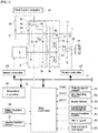
- FIG. 2 shows a detailed configuration of a shift control system of the first embodiment.
- FIG. 3 is an explanatory diagram of the engagement clutch of the first embodiment. Below, with reference to FIGS. 2 and 3 , a detailed configuration of the shift control system in the first embodiment is described.
- an engagement clutch 8c, a friction clutch 9c, a parking gear 17, a driving motor generator 2, a hydraulic brake 15, a shift controller 21 are provided.
- the engagement clutch 8c, the friction clutch 9c, the driving motor generator 2, and the hydraulic brake 15 are subject to control, and depending on conditions, control is executed based on a request from the shift controller 21.
- the engagement clutch 8c is constructed in a clutch of synchronous meshing type, and includes a clutch gear 8a(first engagement member) provided on the gear 8d and a clutch hub (second engagement member) 8e attached to the transmission output shaft 7, and a coupling sleeve 8f (see FIG. 1 ). Further, by driving in stroke the coupling sleeve 8f by the first electric actuator 41, meshing engagement/release between the clutch gear 8d and the clutch hub 8e is performed via the coupling sleeve 8f. Note that, since the gear 8a is meshed with the gear 8b jointly rotatable with the transmission input shaft 6, the clutch gear 8d provided on the gear 8a is coupled to the transmission input shaft 6. In other words, when the clutch gear 8d and the clutch hub 8e are engaged by meshing, the transmission input shaft 6 and the transmission output shaft 7 are coupled.
- the meshing engagement or release of the engagement clutch 8c is determined by the position of the coupling sleeve 8f.
- the shift controller 21 reads the value of the sleeve position sensor 27 and is provided with a first position servo controller 51 (for example, position servo system with PID control) which provides a current to the first electric actuator 41, so that the position of the coupling sleeve 8f is located in the meshing engagement position or the release position.
- a first position servo controller 51 for example, position servo system with PID control
- the coupling sleeve 8f is formed in a cylindrical shape with both ends open and provided at its inner periphery with a plurality of spline portions 8fa constantly fit with clutch teeth (not shown) of the clutch gear 8d (see FIG. 1 ). Further, while maintaining a fitting state between the clutch teeth of the clutch gear 8d and the spline portions 8fa, the coupling sleeve 8f is supported movably axially, i.e., in the left-right direction in FIG. 3A . The axial movement of the coupling sleeve 8f is made by driving the first electric actuator 41 (see FIG. 2 ).
- the clutch hub 8e is formed with a plurality of clutch teeth 8ea on the outer periphery thereof, which may be fit into the spline portions 8fa formed on the inner periphery of the coupling sleeve 8f. That is, the clutch teeth 8ea of the clutch hub 8e will be engageable with the clutch teeth of the clutch gear 8d (not shown) via the coupling sleeve 8f. Furthermore, in the clutch hub 8e, the outer periphery of a tapered cone portion 8eb is fitted with a synchronizer ring 8g movably in the axial direction.
- the synchronizer ring 8g is formed with a plurality of synchro-teeth 8ga which can mesh with a plurality of the spline portions 8fa of the coupling sleeve 8f and key grooves 8gc which constantly mesh with keys 8h provided on the coupling sleeve 8f.
- a gap is provided between the key 8h and the key groove 8gc.
- the synchronizer ring 8g is configured to be movable in the rotational direction relative to the coupling sleeve 8f by the amount of the gap between the key 8h and the key groove 8gc.
- a chamfer portion 8gb of the synchro-teeth 8ga of the synchronizer ring 8g and a chamfer portion 8fb of the spline portion 8fa of the coupling sleeve 8f, as shown in FIG. 3B are brought into an index state, i.e., facing each other when viewed in the axial direction.
- both chamfer portions 8fb, 8gb are brought into contact each other.
- the synchronizer ring 8g further presses the cone portion 8eb to generate the friction torque so that the synchronizer ring 8g, the coupling sleeve 8f, and the clutch hub 8e are synchronized.
- the synchronizer ring 8g rotates in the circumferential direction such that the spline portion 8fa is to mate with synchro-teeth 8ga,.
- the friction clutch 9c includes a driven plate 9d which rotates together with the gear 9a, and a drive plate 9e which rotates together with the transmission input shaft 6 (see FIG. 1 ). Further, by driving a slider 9f to impart a pressing force to both plates 9d, 9e by a second electric actuator 42, the frictional engagement/release is performed.
- the transmission torque capacity of the frictional clutch 9c is determined by a position of the slider 9f.
- the slider 9f is a screw mechanism, so that, when the input of the second electric actuator 42 is 0 (zero), the position is configured to be held.
- the shift controller 21 reads the value of the slider position sensor 26 and is provided with a second position servo controller 52 (for example, position servo system by PID control) so that a slider position for obtaining a desired transmission torque capacity may be achieved.
- the friction clutch 9c rotates jointly with the transmission input shaft 6, and drivingly connects the gear 9a to the transmission input shaft 6 when frictionally engaged, and, when releasing, separates the drive connection between the gear 9a and the transmission input shaft 6.
- the motor generator 2 is placed under a torque control or rotation speed control by a motor controller 28 which receives a command output from the shift controller 21.
- a motor controller 28 which receives a command output from the shift controller 21.
- the driving motor generator 2 will be placed under the torque control or the rotation speed control.
- the hydraulic brake 15 is increased in the braking engagement force by a pump-up operation by a brake hydraulic pressure actuator (not shown) which receives a driving request from the brake controller 29 which in turn receives a request from the shift controller 21.
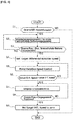
- FIG. 4 shows a flow of a shift control process executed by the shift controller in the first embodiment. Below, based on FIG. 4 , a description is given of each step representing a shift control processing configuration.
- step S1 it is determined whether or not a downshift request from a high gear stage to a low gear stage has been generated.
- YES downshift request present
- NO no downshift request
- the downshift request is output, on the shift map(not shown) which is set based on the accelerator opening and the vehicle speed, when an operating point determined by the accelerator opening and the vehicle speed crosses a downshift line.
- step S2 following the determination that the downshift request is present in step S1, the coupling sleeve 8f of the engagement clutch 8c starts a stroke drive by the first electric actuator 41. Subsequently to the coupling sleeve being displaced immediately before engagement position of the engagement clutch 8c, control proceeds to step S3.
- a position immediately before engagement of the engagement clutch 8c is intended to refer to a position in which the tip position of the spline portion 8fa on the clutch hub side of the coupling sleeve 8f into which the clutch gear 8d fits is positioned immediately before the overlapping with the synchro-teeth 8ga of the synchronizer ring 8g.
- the position in which the distance between the clutch hub side tip of the spline portion 8fa and the synchro-teeth 8ga assumes a very small predetermined value refers to the "position immediately before engagement of the engagement clutch 8c".
- step S4 following the determination that the sleeve position is equal to the position immediately before engagement, a target differential speed to impart a predetermined differential rotation speed is set between the rotation speed of the cutch gear 8d and the rotation speed of the cutch hub 8e. Then control proceeds to step S5.
- the "target differential rotation speed to impart a predetermined differential rotation speed” is intended to refer to a very small rotational speed difference which would not remain the clutch teeth 8ea of the clutch hub 8e and the spline portion 8fa of the coupling sleeve 8f to be opposed to each other, when the coupling sleeve 8f being engaged with the clutch gear 8d will engage with the clutch hub 8e due to a stroke drive.
- the rotational speed difference is set such that, even when the clutch teeth 8ea and the spline 8fa are opposed to each other, the relative position of both components is shifted promptly to engage or mesh each other.
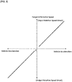
- the target differential speed is set, with reference to a map shown in FIG. 5 , according to a vehicle speed detected by a vehicle speed sensor 22 and vehicle acceleration or vehicle deceleration detected by a longitudinal acceleration sensor 25.
- the rotation speed of the clutch gear 8d representative of a clutch input rotation speed is set to be higher than the rotation speed of the clutch hub 8e representative of the clutch output rotation speed.
- the target differential rotation speed is set greater.
- the target differential rotation speed is set such that the rotation speed of the clutch gear 8d will be lower than the rotation speed of the clutch hub 8e.
- the target differential rotation speed is set greater.
- step S5 following the target differential rotation speed setting in step S4, the rotation speed (motor rotation speed)of the driving motor generator 2representative of the input rotation speed of the automatic transmission is controlled, and control proceeds to step S6.
- the input-side rotation speed of the engagement clutch 8c changes, and the differential rotation speed (difference in rotation speed between the rotation speed of the cutch gear 8d and the rotation speed of the cutch hub 8e) at the engagement clutch 8c will be controlled.
- the motor speed control is performed by a feedback control based on the detected values of the motor rotation speed sensor 33 and transmission output speed sensor 34.
- step S7 following the determination of the actual rotational speed difference being equal to the target difference rotation speed in step S6, in the engagement clutch 8c, the coupling sleeve 8f is allowed to stroke driven by the first electric actuator 41. Then, after the coupling sleeve 8f is displaced to a position of meshing with the clutch hub 8e, control proceeds to step S8.
- step S9 following the determination of the sleeve position being equal to the engagement position in step S8, the target differential speed for engaging the clutch 8c is set to zero, and at the same time, the motor speed control is performed to achieve the target motor differential rotation speed. Subsequently, control ends.
- FIG. 6 is a time chart which shows, in the electric vehicle equipped with the control device of the first embodiment during downshifting, each characteristic including an accelerator pedal opening, a target motor rotation speed, a target input rotation speed of the engagement clutch, a target output rotation speed of the engagement clutch, and a coupling sleeve position, respectively.
- each characteristic including an accelerator pedal opening, a target motor rotation speed, a target input rotation speed of the engagement clutch, a target output rotation speed of the engagement clutch, and a coupling sleeve position, respectively.
- step S1 of the flowchart shown in FIG. 4 control proceeds to step S2.
- the coupling sleeve 8f of the engagement clutch 8c is stroke driven by the first electric actuator 41, and the coupling sleeve 8f is displaced to a position until just before engagement with the clutch hub 8e.
- step S3 when the coupling sleeve 8f has reached the position immediately before engagement, control proceeds through step S3 to S4, in which the target differential rotation speed of the engagement clutch 8c is set to a predetermined differential rotation speed imparting value. Furthermore, in accordance with the target differential speed, the target motor rotational speed of the driving motor generator 2 is set to achieve the target differential rotation speed.
- the target motor rotation speed is set such that the motor rotation speed representative of the automatic transmission input rotation speed exceeds the automatic transmission output rotation speed in order for the motor rotation speed to exceed the output rotation speed (cumulative value obtained by multiplying the automatic transmission input rotation speed by gear ratio of the automatic transmission 3). Subsequently, control proceeds to step S5 to thereby execute the motor rotation speed control.
- step S6 when the differential rotation occurs between a target value of cutch input rotation speed of the engagement clutch 8c and a target value of the cutch output rotation speed, and, at time t4, when it is determined that the actual differential rotation speed has reached the target differential rotation speed, control proceeds through step S6, step S7. Subsequently, the coupling sleeve 8f is stroke driven again to start the displacement toward the engaged position.
- the actual differential speed is calculated by subtracting the rotation speed of the transmission output shaft 7 detected by the transmission output speed sensor 34 from the rotation speed of transmission input shaft 6 detected by the motor rotation speed sensor 33.
- the coupling sleeve 8f is stroke driven, the relative positional relationship between the spline portion 8fa and clutch teeth 8ea continues to change until engagement with the clutch hub 8e so that the tip of the spline portion 8fa may avoid collision with the tip of the clutch teeth 8ea.
- the coupling sleeve 8f and the clutch hub 8e can be engaged smoothly so that it is possible to prevent the occurrence of meshing failure in which both components do not mesh with each other. Also, since the meshing failure is not generated, a wasted time such as redoing of the fastening operation would not be generated. Thus, it is possible to shorten the shift time.
- step S8 and step S9 control proceeds through step S8 and step S9, and the target differential rotation speed of the engagement clutch 8c will be set to zero. Also, in response to the target differential rotation speed being set to zero, in order to achieve the target differential rotation speed, the target motor rotation speed of the driving motor generator 2 is set.
- the motor rotation speed representative of the transmission input speed has been set to the differential rotation higher than the transmission output rotation speed, the motor rotation speed will be reduced to match the output rotation speed (value of transmission input rotation speed multiplied by the gear ratio after shifting of the automatic transmission 3). Accordingly, the motor rotation speed control is executed.
- the coupling sleeve 8f of the engagement clutch 8c has been stroke driven previously until a position immediately before engagement.
- the motor rotation speed control is carried out to reach the target differential rotation speed.
- the friction clutch 9c that is being in frictional engagement is changed to be slip-engaged, and then the engagement operation of engagement clutch 8c is carried out.
- the rotation speed of the clutch gear 8d representative of the input rotation speed is set higher than the rotation speed of the clutch hub 8e representative of the output rotation speed.
- the rotation speed of the clutch gear 8d is set lower than the rotation speed of the clutch hub 8e.
- the target differential rotation speed is set greater.
- the target differential rotation speed is greater, the relative displacement speed between the tip of the spline portion 8fa of the coupling sleeve 8f and the tip of the clutch teeth 8ea of the clutch hub 8e is faster, it is possible to perform the engagement operation in the engagement clutch 8c quickly.
- the target differential rotation speed is smaller, it is possible to suppress a shock (engagement shock) when engaging the coupling sleeve 8f with the clutch hub 8e.
- the automatic transmission control device has been described above based on the first embodiment. However, the detailed configurations are not limited to this embodiment.
- the automatic transmission 3 has an engagement clutch 8c and a friction clutch 9c.
- the automatic transmission may include only an engagement clutch as engaging element.
- the engagement clutch 8c includes a synchronization mechanism.
- the present invention is applicable to a so-called dog clutch which is not provided with such synchronization mechanism.
- the engagement clutch 8c is coupled with the clutch gear 8d representative of a first engagement member meshed with the clutch hub 8e representative of a second engagement member via the coupling sleeve 8f.
- the configuration is not limited to this example.
- the first engagement member may be directly meshed with the second engagement member.
- the "position immediately before the engagement of the engaging clutch 8c" is intended to describe a position of the clutch hub side tip of the spline portion 8fa of the coupling sleeve 8f assumes a position immediately before overlapping when viewed in the axial direction with the synchro-tooth 8ga of the synchronizer ring 8g.
- the configuration is not limited to this example.
- the position in which a gap between the first engagement member and the second engagement member assumes a negligible, predetermined value may be referred to as the "position immediately before the engagement of the engaging clutch 8c".
- the " position immediately before the engagement of the engaging clutch 8c" is defined as such a position in which the first engagement member (or a member such as the coupling sleeve 8f which is subject to meshing with the first engagement member) and the second engagement member may be meshed in a very short time.
- the driving source is comprised of only a driving motor/generator 2.
- the driving force is not limited to this configuration.
- the driving force may include both a motor and an engine, or may be comprised of an engine only.
Landscapes
- Engineering & Computer Science (AREA)
- General Engineering & Computer Science (AREA)
- Mechanical Engineering (AREA)
- Control Of Transmission Device (AREA)
- Hydraulic Clutches, Magnetic Clutches, Fluid Clutches, And Fluid Joints (AREA)
- Electric Propulsion And Braking For Vehicles (AREA)
- Hybrid Electric Vehicles (AREA)
Claims (4)
- Dispositif de commande de transmission automatique,
doté d'une transmission automatique (3) ayant un embrayage d'engagement (8c) et d'une unité de commande de changement de vitesse (21)
dans lequel l'embrayage d'engagement (8c) est disposé dans un système d'entraînement de véhicule et fonctionne selon un engagement par engrènement en tant qu'élément de couplage,
dans lequel l'unité de commande de changement de vitesse (21) est configurée pour exécuter une commande de changement de vitesse de la transmission automatique (3),
dans lequel l'embrayage d'engagement (8c) est doté d'un premier élément d'engagement (8a, 8d) et d'un deuxième élément d'engagement (8e),
dans lequel le premier élément d'engagement (8a, 8d) est relié à un arbre d'entrée de transmission (6) et le deuxième élément d'engagement (8e) est relié à un arbre de sortie de transmission (7) et capable de s'engrener avec le premier élément d'engagement (8a, 8d),
dans lequel l'unité de commande de changement de vitesse (21) est configurée pour définir une vitesse de rotation différentielle cible lors de l'engagement de l'embrayage d'engagement (8c) pour un changement de vitesse de sorte que lorsque le premier élément d'engagement (8a, 8d) et le deuxième élément d'engagement (8e) s'engrènent mutuellement, une rotation différentielle prédéterminée soit communiquée entre une vitesse de rotation d'entrée représentant la vitesse de rotation du premier élément d'engagement (8a, 8d) et une vitesse de rotation de sortie représentant la vitesse de rotation du deuxième élément d'engagement (8e), et
dans lequel l'amplitude de la vitesse de rotation différentielle cible est définie en fonction de l'amplitude de l'accélération du véhicule de sorte que, à mesure que l'amplitude de l'accélération du véhicule augmente, la vitesse de rotation différentielle cible soit définie pour être supérieure. - Dispositif de commande de transmission automatique tel que revendiqué dans la revendication 1, dans lequel l'unité de commande de changement de vitesse (21) est configurée de sorte que, lors de l'engagement de l'embrayage d'engagement (8c) pour effectuer un changement de vitesse à un moment où le véhicule décélère, la vitesse de rotation d'entrée soit définie pour être inférieure à la vitesse de rotation de sortie de sorte que la vitesse de rotation différentielle cible augmente à mesure que l'amplitude de la décélération de véhicule augmente.
- Dispositif de commande de transmission automatique tel que revendiqué dans la revendication 1 ou 2, dans lequel l'unité de commande de changement de vitesse (21) est configurée de sorte que, lors de l'engagement de l'embrayage d'engagement (8c) pour effectuer un changement de vitesse à un moment où le véhicule accélère, la vitesse de rotation d'entrée soit définie pour être supérieure à la vitesse de rotation de sortie de sorte que la vitesse de rotation différentielle cible augmente à mesure que l'amplitude de l'accélération de véhicule augmente.
- Dispositif de commande de transmission automatique tel que revendiqué dans l'une quelconque des revendications précédentes, dans lequel l'unité de commande de changement de vitesse (21) est configurée de sorte que, lors de l'engagement de l'embrayage d'engagement (8c) pour le changement de vitesse, la vitesse de rotation d'entrée de la transmission automatique (3) soit réglée sur la vitesse de rotation différentielle cible après qu'une position de course relative entre le premier élément d'engagement (8a, 8d) et le deuxième élément d'engagement (8e) a été amenée à une position immédiatement avant l'engagement.
Applications Claiming Priority (2)
| Application Number | Priority Date | Filing Date | Title |
|---|---|---|---|
| JP2013230680 | 2013-11-06 | ||
| PCT/JP2014/078191 WO2015068584A1 (fr) | 2013-11-06 | 2014-10-23 | Dispositif de commande de transmission automatique |
Publications (3)
| Publication Number | Publication Date |
|---|---|
| EP3067589A1 EP3067589A1 (fr) | 2016-09-14 |
| EP3067589A4 EP3067589A4 (fr) | 2017-04-26 |
| EP3067589B1 true EP3067589B1 (fr) | 2020-02-26 |
Family
ID=53041366
Family Applications (1)
| Application Number | Title | Priority Date | Filing Date |
|---|---|---|---|
| EP14860834.2A Active EP3067589B1 (fr) | 2013-11-06 | 2014-10-23 | Dispositif de commande de transmission automatique |
Country Status (5)
| Country | Link |
|---|---|
| US (1) | US9695933B2 (fr) |
| EP (1) | EP3067589B1 (fr) |
| JP (1) | JP6056985B2 (fr) |
| CN (1) | CN105637265B (fr) |
| WO (1) | WO2015068584A1 (fr) |
Families Citing this family (11)
| Publication number | Priority date | Publication date | Assignee | Title |
|---|---|---|---|---|
| EP3426948B1 (fr) * | 2016-03-06 | 2021-09-29 | Dana Belgium N.V. | Chaîne cinématique pour un véhicule comprenant un moteur d'entraînement électrique et une servotransmission ayant au moins deux étages de transmission |
| JP6339620B2 (ja) * | 2016-03-31 | 2018-06-06 | 本田技研工業株式会社 | 自動変速機の変速制御装置 |
| WO2018124219A1 (fr) * | 2016-12-27 | 2018-07-05 | アイシン・エーアイ株式会社 | Dispositif de commande de transmission de puissance |
| CN110114597B (zh) * | 2016-12-27 | 2021-02-02 | 爱信艾达株式会社 | 动力传递控制装置 |
| NL2018971B1 (en) * | 2017-05-24 | 2018-12-07 | Punch Powertrain Nv | a shifting method for a transmission, a transmission system, a computer program product, and a vehicle. |
| JP7090984B2 (ja) * | 2018-06-27 | 2022-06-27 | 日野自動車株式会社 | ハイブリッド自動車の変速支援方法及び装置 |
| JP7492896B2 (ja) * | 2020-10-12 | 2024-05-30 | カワサキモータース株式会社 | ギヤ変速機付き車両の制御装置及び制御方法 |
| CN112648308B (zh) * | 2020-12-30 | 2022-04-29 | 蜂巢传动科技河北有限公司 | 基于离合器调节同步器两端速差的控制方法、装置及系统 |
| JP2022146837A (ja) * | 2021-03-22 | 2022-10-05 | 株式会社イケヤフォ-ミュラ | 噛み合いクラッチ機構、摩擦クラッチ機構、及び2段変速装置 |
| DE102021213655A1 (de) * | 2021-12-02 | 2023-06-07 | Zf Friedrichshafen Ag | Kopplungsvorrichtung für ein Kraftfahrzeug |
| CN115789238B (zh) * | 2022-10-28 | 2026-04-10 | 重庆青山工业有限责任公司 | 自动变速器离合器输入转速调速的调度控制方法 |
Family Cites Families (12)
| Publication number | Priority date | Publication date | Assignee | Title |
|---|---|---|---|---|
| US5425284A (en) | 1993-09-07 | 1995-06-20 | Eaton Corporation | Automated mechanical transmission control system/method |
| JP3562401B2 (ja) | 1999-09-22 | 2004-09-08 | 株式会社日立製作所 | 自動変速機の制御装置 |
| JP3685149B2 (ja) * | 2002-04-25 | 2005-08-17 | トヨタ自動車株式会社 | 車両用駆動制御装置 |
| JP4200075B2 (ja) * | 2003-10-10 | 2008-12-24 | 株式会社日立製作所 | 自動車の変速方法,自動車の変速装置,自動車用変速機の制御装置,自動車の変速装置のアクチュエータ制御装置 |
| JP2006038136A (ja) | 2004-07-28 | 2006-02-09 | Toyota Motor Corp | 駆動装置 |
| JP4177384B2 (ja) * | 2006-04-12 | 2008-11-05 | 三菱電機株式会社 | 変速装置 |
| JP2008075718A (ja) * | 2006-09-20 | 2008-04-03 | Mitsubishi Fuso Truck & Bus Corp | 車両用変速制御装置 |
| WO2010119504A1 (fr) * | 2009-04-14 | 2010-10-21 | トヨタ自動車株式会社 | Dispositif de commande d'entraînement de véhicule |
| US8734294B2 (en) * | 2010-11-22 | 2014-05-27 | Toyota Jidosha Kabushiki Kaisha | Control device of vehicle power transmission device |
| JP5664764B2 (ja) * | 2011-03-23 | 2015-02-04 | トヨタ自動車株式会社 | 車両用駆動装置 |
| GB2495564B (en) | 2011-11-22 | 2014-11-05 | Jaguar Land Rover Ltd | A method and a control unit for controlling the engagement of an input gear with an output gear |
| JP2014105826A (ja) | 2012-11-29 | 2014-06-09 | Fuji Heavy Ind Ltd | クラッチ制御装置 |
-
2014
- 2014-10-23 EP EP14860834.2A patent/EP3067589B1/fr active Active
- 2014-10-23 JP JP2015546597A patent/JP6056985B2/ja active Active
- 2014-10-23 CN CN201480056887.4A patent/CN105637265B/zh active Active
- 2014-10-23 WO PCT/JP2014/078191 patent/WO2015068584A1/fr not_active Ceased
- 2014-10-23 US US15/025,290 patent/US9695933B2/en active Active
Non-Patent Citations (1)
| Title |
|---|
| None * |
Also Published As
| Publication number | Publication date |
|---|---|
| WO2015068584A1 (fr) | 2015-05-14 |
| CN105637265A (zh) | 2016-06-01 |
| CN105637265B (zh) | 2018-10-09 |
| JP6056985B2 (ja) | 2017-01-11 |
| JPWO2015068584A1 (ja) | 2017-03-09 |
| EP3067589A1 (fr) | 2016-09-14 |
| US9695933B2 (en) | 2017-07-04 |
| US20160230881A1 (en) | 2016-08-11 |
| EP3067589A4 (fr) | 2017-04-26 |
Similar Documents
| Publication | Publication Date | Title |
|---|---|---|
| EP3067589B1 (fr) | Dispositif de commande de transmission automatique | |
| US9937925B2 (en) | Shift control method for hybrid vehicle with DCT | |
| US20150375750A1 (en) | Automatic transmission control device | |
| WO2014175080A1 (fr) | Dispositif de commande de véhicule hybride | |
| CN104251303A (zh) | 自动变速器控制设备 | |
| JP2014121225A (ja) | 電気自動車の変速制御装置および変速制御方法 | |
| WO2013176074A1 (fr) | Procédé de commande de changement de vitesse pour véhicule électrique et dispositif de commande de changement de vitesse | |
| JP6070294B2 (ja) | 車両の変速制御装置 | |
| EP2937601B1 (fr) | Dispositif de commande de transmission automatique | |
| JP2015087001A (ja) | 自動変速機の制御装置 | |
| JP5972091B2 (ja) | ハイブリッド車両 | |
| EP4316897B1 (fr) | Dispositif d'entraînement de véhicule | |
| WO2014136364A1 (fr) | Dispositif de commande de changement de rapport de véhicule | |
| WO2022118896A1 (fr) | Dispositif d'entraînement pour véhicule | |
| JP2015090197A (ja) | パーキングアクチュエータの制御装置 | |
| EP2815944A1 (fr) | Appareil de commande de véhicule hybride | |
| JP6089802B2 (ja) | 車両の変速制御装置 | |
| JP2022087708A (ja) | 車両用駆動装置 | |
| JP6209834B2 (ja) | 自動変速機の制御装置 | |
| WO2022158537A1 (fr) | Dispositif d'entraînement pour véhicule | |
| JP6384221B2 (ja) | 電動車両の変速制御装置 | |
| JP2014173672A (ja) | 車両の変速制御装置 | |
| JP2014125087A (ja) | 自動変速機の制御装置 | |
| JP5831253B2 (ja) | ハイブリッド車両の制御装置 | |
| JP2015113865A (ja) | 車両用自動変速機 |
Legal Events
| Date | Code | Title | Description |
|---|---|---|---|
| PUAI | Public reference made under article 153(3) epc to a published international application that has entered the european phase |
Free format text: ORIGINAL CODE: 0009012 |
|
| 17P | Request for examination filed |
Effective date: 20160419 |
|
| AK | Designated contracting states |
Kind code of ref document: A1 Designated state(s): AL AT BE BG CH CY CZ DE DK EE ES FI FR GB GR HR HU IE IS IT LI LT LU LV MC MK MT NL NO PL PT RO RS SE SI SK SM TR |
|
| AX | Request for extension of the european patent |
Extension state: BA ME |
|
| DAX | Request for extension of the european patent (deleted) | ||
| A4 | Supplementary search report drawn up and despatched |
Effective date: 20170327 |
|
| RIC1 | Information provided on ipc code assigned before grant |
Ipc: F16H 61/04 20060101AFI20170321BHEP |
|
| STAA | Information on the status of an ep patent application or granted ep patent |
Free format text: STATUS: EXAMINATION IS IN PROGRESS |
|
| 17Q | First examination report despatched |
Effective date: 20171214 |
|
| GRAP | Despatch of communication of intention to grant a patent |
Free format text: ORIGINAL CODE: EPIDOSNIGR1 |
|
| STAA | Information on the status of an ep patent application or granted ep patent |
Free format text: STATUS: GRANT OF PATENT IS INTENDED |
|
| INTG | Intention to grant announced |
Effective date: 20191121 |
|
| GRAS | Grant fee paid |
Free format text: ORIGINAL CODE: EPIDOSNIGR3 |
|
| GRAA | (expected) grant |
Free format text: ORIGINAL CODE: 0009210 |
|
| STAA | Information on the status of an ep patent application or granted ep patent |
Free format text: STATUS: THE PATENT HAS BEEN GRANTED |
|
| RIN1 | Information on inventor provided before grant (corrected) |
Inventor name: KOGA, MASATO Inventor name: MORI, KENICHI Inventor name: TSUKIZAKI, ATSUSHI Inventor name: TOYOTA, RYOHEY Inventor name: TAKAKI, KAZUHIRO Inventor name: KURITA, TAKASHI |
|
| RAP1 | Party data changed (applicant data changed or rights of an application transferred) |
Owner name: NISSAN MOTOR CO., LTD. |
|
| AK | Designated contracting states |
Kind code of ref document: B1 Designated state(s): AL AT BE BG CH CY CZ DE DK EE ES FI FR GB GR HR HU IE IS IT LI LT LU LV MC MK MT NL NO PL PT RO RS SE SI SK SM TR |
|
| REG | Reference to a national code |
Ref country code: GB Ref legal event code: FG4D |
|
| REG | Reference to a national code |
Ref country code: CH Ref legal event code: EP |
|
| REG | Reference to a national code |
Ref country code: AT Ref legal event code: REF Ref document number: 1238025 Country of ref document: AT Kind code of ref document: T Effective date: 20200315 |
|
| REG | Reference to a national code |
Ref country code: IE Ref legal event code: FG4D |
|
| REG | Reference to a national code |
Ref country code: DE Ref legal event code: R096 Ref document number: 602014061671 Country of ref document: DE |
|
| PG25 | Lapsed in a contracting state [announced via postgrant information from national office to epo] |
Ref country code: NO Free format text: LAPSE BECAUSE OF FAILURE TO SUBMIT A TRANSLATION OF THE DESCRIPTION OR TO PAY THE FEE WITHIN THE PRESCRIBED TIME-LIMIT Effective date: 20200526 Ref country code: FI Free format text: LAPSE BECAUSE OF FAILURE TO SUBMIT A TRANSLATION OF THE DESCRIPTION OR TO PAY THE FEE WITHIN THE PRESCRIBED TIME-LIMIT Effective date: 20200226 Ref country code: RS Free format text: LAPSE BECAUSE OF FAILURE TO SUBMIT A TRANSLATION OF THE DESCRIPTION OR TO PAY THE FEE WITHIN THE PRESCRIBED TIME-LIMIT Effective date: 20200226 |
|
| REG | Reference to a national code |
Ref country code: NL Ref legal event code: MP Effective date: 20200226 |
|
| REG | Reference to a national code |
Ref country code: LT Ref legal event code: MG4D |
|
| PG25 | Lapsed in a contracting state [announced via postgrant information from national office to epo] |
Ref country code: HR Free format text: LAPSE BECAUSE OF FAILURE TO SUBMIT A TRANSLATION OF THE DESCRIPTION OR TO PAY THE FEE WITHIN THE PRESCRIBED TIME-LIMIT Effective date: 20200226 Ref country code: BG Free format text: LAPSE BECAUSE OF FAILURE TO SUBMIT A TRANSLATION OF THE DESCRIPTION OR TO PAY THE FEE WITHIN THE PRESCRIBED TIME-LIMIT Effective date: 20200526 Ref country code: LV Free format text: LAPSE BECAUSE OF FAILURE TO SUBMIT A TRANSLATION OF THE DESCRIPTION OR TO PAY THE FEE WITHIN THE PRESCRIBED TIME-LIMIT Effective date: 20200226 Ref country code: GR Free format text: LAPSE BECAUSE OF FAILURE TO SUBMIT A TRANSLATION OF THE DESCRIPTION OR TO PAY THE FEE WITHIN THE PRESCRIBED TIME-LIMIT Effective date: 20200527 Ref country code: SE Free format text: LAPSE BECAUSE OF FAILURE TO SUBMIT A TRANSLATION OF THE DESCRIPTION OR TO PAY THE FEE WITHIN THE PRESCRIBED TIME-LIMIT Effective date: 20200226 Ref country code: IS Free format text: LAPSE BECAUSE OF FAILURE TO SUBMIT A TRANSLATION OF THE DESCRIPTION OR TO PAY THE FEE WITHIN THE PRESCRIBED TIME-LIMIT Effective date: 20200626 |
|
| PG25 | Lapsed in a contracting state [announced via postgrant information from national office to epo] |
Ref country code: NL Free format text: LAPSE BECAUSE OF FAILURE TO SUBMIT A TRANSLATION OF THE DESCRIPTION OR TO PAY THE FEE WITHIN THE PRESCRIBED TIME-LIMIT Effective date: 20200226 |
|
| PG25 | Lapsed in a contracting state [announced via postgrant information from national office to epo] |
Ref country code: RO Free format text: LAPSE BECAUSE OF FAILURE TO SUBMIT A TRANSLATION OF THE DESCRIPTION OR TO PAY THE FEE WITHIN THE PRESCRIBED TIME-LIMIT Effective date: 20200226 Ref country code: CZ Free format text: LAPSE BECAUSE OF FAILURE TO SUBMIT A TRANSLATION OF THE DESCRIPTION OR TO PAY THE FEE WITHIN THE PRESCRIBED TIME-LIMIT Effective date: 20200226 Ref country code: EE Free format text: LAPSE BECAUSE OF FAILURE TO SUBMIT A TRANSLATION OF THE DESCRIPTION OR TO PAY THE FEE WITHIN THE PRESCRIBED TIME-LIMIT Effective date: 20200226 Ref country code: SM Free format text: LAPSE BECAUSE OF FAILURE TO SUBMIT A TRANSLATION OF THE DESCRIPTION OR TO PAY THE FEE WITHIN THE PRESCRIBED TIME-LIMIT Effective date: 20200226 Ref country code: LT Free format text: LAPSE BECAUSE OF FAILURE TO SUBMIT A TRANSLATION OF THE DESCRIPTION OR TO PAY THE FEE WITHIN THE PRESCRIBED TIME-LIMIT Effective date: 20200226 Ref country code: DK Free format text: LAPSE BECAUSE OF FAILURE TO SUBMIT A TRANSLATION OF THE DESCRIPTION OR TO PAY THE FEE WITHIN THE PRESCRIBED TIME-LIMIT Effective date: 20200226 Ref country code: ES Free format text: LAPSE BECAUSE OF FAILURE TO SUBMIT A TRANSLATION OF THE DESCRIPTION OR TO PAY THE FEE WITHIN THE PRESCRIBED TIME-LIMIT Effective date: 20200226 Ref country code: SK Free format text: LAPSE BECAUSE OF FAILURE TO SUBMIT A TRANSLATION OF THE DESCRIPTION OR TO PAY THE FEE WITHIN THE PRESCRIBED TIME-LIMIT Effective date: 20200226 Ref country code: PT Free format text: LAPSE BECAUSE OF FAILURE TO SUBMIT A TRANSLATION OF THE DESCRIPTION OR TO PAY THE FEE WITHIN THE PRESCRIBED TIME-LIMIT Effective date: 20200719 |
|
| REG | Reference to a national code |
Ref country code: AT Ref legal event code: MK05 Ref document number: 1238025 Country of ref document: AT Kind code of ref document: T Effective date: 20200226 |
|
| REG | Reference to a national code |
Ref country code: DE Ref legal event code: R097 Ref document number: 602014061671 Country of ref document: DE |
|
| PLBE | No opposition filed within time limit |
Free format text: ORIGINAL CODE: 0009261 |
|
| STAA | Information on the status of an ep patent application or granted ep patent |
Free format text: STATUS: NO OPPOSITION FILED WITHIN TIME LIMIT |
|
| PG25 | Lapsed in a contracting state [announced via postgrant information from national office to epo] |
Ref country code: IT Free format text: LAPSE BECAUSE OF FAILURE TO SUBMIT A TRANSLATION OF THE DESCRIPTION OR TO PAY THE FEE WITHIN THE PRESCRIBED TIME-LIMIT Effective date: 20200226 Ref country code: AT Free format text: LAPSE BECAUSE OF FAILURE TO SUBMIT A TRANSLATION OF THE DESCRIPTION OR TO PAY THE FEE WITHIN THE PRESCRIBED TIME-LIMIT Effective date: 20200226 |
|
| 26N | No opposition filed |
Effective date: 20201127 |
|
| PG25 | Lapsed in a contracting state [announced via postgrant information from national office to epo] |
Ref country code: PL Free format text: LAPSE BECAUSE OF FAILURE TO SUBMIT A TRANSLATION OF THE DESCRIPTION OR TO PAY THE FEE WITHIN THE PRESCRIBED TIME-LIMIT Effective date: 20200226 Ref country code: SI Free format text: LAPSE BECAUSE OF FAILURE TO SUBMIT A TRANSLATION OF THE DESCRIPTION OR TO PAY THE FEE WITHIN THE PRESCRIBED TIME-LIMIT Effective date: 20200226 |
|
| REG | Reference to a national code |
Ref country code: CH Ref legal event code: PL |
|
| PG25 | Lapsed in a contracting state [announced via postgrant information from national office to epo] |
Ref country code: MC Free format text: LAPSE BECAUSE OF FAILURE TO SUBMIT A TRANSLATION OF THE DESCRIPTION OR TO PAY THE FEE WITHIN THE PRESCRIBED TIME-LIMIT Effective date: 20200226 Ref country code: LU Free format text: LAPSE BECAUSE OF NON-PAYMENT OF DUE FEES Effective date: 20201023 |
|
| REG | Reference to a national code |
Ref country code: BE Ref legal event code: MM Effective date: 20201031 |
|
| PG25 | Lapsed in a contracting state [announced via postgrant information from national office to epo] |
Ref country code: CH Free format text: LAPSE BECAUSE OF NON-PAYMENT OF DUE FEES Effective date: 20201031 Ref country code: BE Free format text: LAPSE BECAUSE OF NON-PAYMENT OF DUE FEES Effective date: 20201031 Ref country code: LI Free format text: LAPSE BECAUSE OF NON-PAYMENT OF DUE FEES Effective date: 20201031 |
|
| PG25 | Lapsed in a contracting state [announced via postgrant information from national office to epo] |
Ref country code: IE Free format text: LAPSE BECAUSE OF NON-PAYMENT OF DUE FEES Effective date: 20201023 |
|
| PG25 | Lapsed in a contracting state [announced via postgrant information from national office to epo] |
Ref country code: TR Free format text: LAPSE BECAUSE OF FAILURE TO SUBMIT A TRANSLATION OF THE DESCRIPTION OR TO PAY THE FEE WITHIN THE PRESCRIBED TIME-LIMIT Effective date: 20200226 Ref country code: MT Free format text: LAPSE BECAUSE OF FAILURE TO SUBMIT A TRANSLATION OF THE DESCRIPTION OR TO PAY THE FEE WITHIN THE PRESCRIBED TIME-LIMIT Effective date: 20200226 Ref country code: CY Free format text: LAPSE BECAUSE OF FAILURE TO SUBMIT A TRANSLATION OF THE DESCRIPTION OR TO PAY THE FEE WITHIN THE PRESCRIBED TIME-LIMIT Effective date: 20200226 |
|
| PG25 | Lapsed in a contracting state [announced via postgrant information from national office to epo] |
Ref country code: MK Free format text: LAPSE BECAUSE OF FAILURE TO SUBMIT A TRANSLATION OF THE DESCRIPTION OR TO PAY THE FEE WITHIN THE PRESCRIBED TIME-LIMIT Effective date: 20200226 Ref country code: AL Free format text: LAPSE BECAUSE OF FAILURE TO SUBMIT A TRANSLATION OF THE DESCRIPTION OR TO PAY THE FEE WITHIN THE PRESCRIBED TIME-LIMIT Effective date: 20200226 |
|
| PGFP | Annual fee paid to national office [announced via postgrant information from national office to epo] |
Ref country code: GB Payment date: 20250923 Year of fee payment: 12 |
|
| PGFP | Annual fee paid to national office [announced via postgrant information from national office to epo] |
Ref country code: FR Payment date: 20250923 Year of fee payment: 12 |
|
| PGFP | Annual fee paid to national office [announced via postgrant information from national office to epo] |
Ref country code: DE Payment date: 20250923 Year of fee payment: 12 |