EP3067603B1 - Hydraulisches ventil - Google Patents
Hydraulisches ventil Download PDFInfo
- Publication number
- EP3067603B1 EP3067603B1 EP15158775.5A EP15158775A EP3067603B1 EP 3067603 B1 EP3067603 B1 EP 3067603B1 EP 15158775 A EP15158775 A EP 15158775A EP 3067603 B1 EP3067603 B1 EP 3067603B1
- Authority
- EP
- European Patent Office
- Prior art keywords
- valve
- hydraulic
- flow path
- temperature sensor
- insert
- Prior art date
- Legal status (The legal status is an assumption and is not a legal conclusion. Google has not performed a legal analysis and makes no representation as to the accuracy of the status listed.)
- Active
Links
Images



Classifications
-
- F—MECHANICAL ENGINEERING; LIGHTING; HEATING; WEAPONS; BLASTING
- F16—ENGINEERING ELEMENTS AND UNITS; GENERAL MEASURES FOR PRODUCING AND MAINTAINING EFFECTIVE FUNCTIONING OF MACHINES OR INSTALLATIONS; THERMAL INSULATION IN GENERAL
- F16K—VALVES; TAPS; COCKS; ACTUATING-FLOATS; DEVICES FOR VENTING OR AERATING
- F16K37/00—Special means in or on valves or other cut-off apparatus for indicating or recording operation thereof, or for enabling an alarm to be given
- F16K37/0058—Optical means, e.g. light transmission, observation ports
-
- F—MECHANICAL ENGINEERING; LIGHTING; HEATING; WEAPONS; BLASTING
- F16—ENGINEERING ELEMENTS AND UNITS; GENERAL MEASURES FOR PRODUCING AND MAINTAINING EFFECTIVE FUNCTIONING OF MACHINES OR INSTALLATIONS; THERMAL INSULATION IN GENERAL
- F16K—VALVES; TAPS; COCKS; ACTUATING-FLOATS; DEVICES FOR VENTING OR AERATING
- F16K37/00—Special means in or on valves or other cut-off apparatus for indicating or recording operation thereof, or for enabling an alarm to be given
- F16K37/0025—Electrical or magnetic means
- F16K37/005—Electrical or magnetic means for measuring fluid parameters
-
- F—MECHANICAL ENGINEERING; LIGHTING; HEATING; WEAPONS; BLASTING
- F16—ENGINEERING ELEMENTS AND UNITS; GENERAL MEASURES FOR PRODUCING AND MAINTAINING EFFECTIVE FUNCTIONING OF MACHINES OR INSTALLATIONS; THERMAL INSULATION IN GENERAL
- F16K—VALVES; TAPS; COCKS; ACTUATING-FLOATS; DEVICES FOR VENTING OR AERATING
- F16K11/00—Multiple-way valves, e.g. mixing valves; Pipe fittings incorporating such valves
- F16K11/02—Multiple-way valves, e.g. mixing valves; Pipe fittings incorporating such valves with all movable sealing faces moving as one unit
- F16K11/04—Multiple-way valves, e.g. mixing valves; Pipe fittings incorporating such valves with all movable sealing faces moving as one unit comprising only lift valves
-
- F—MECHANICAL ENGINEERING; LIGHTING; HEATING; WEAPONS; BLASTING
- F16—ENGINEERING ELEMENTS AND UNITS; GENERAL MEASURES FOR PRODUCING AND MAINTAINING EFFECTIVE FUNCTIONING OF MACHINES OR INSTALLATIONS; THERMAL INSULATION IN GENERAL
- F16K—VALVES; TAPS; COCKS; ACTUATING-FLOATS; DEVICES FOR VENTING OR AERATING
- F16K27/00—Construction of housing; Use of materials therefor
-
- F—MECHANICAL ENGINEERING; LIGHTING; HEATING; WEAPONS; BLASTING
- F16—ENGINEERING ELEMENTS AND UNITS; GENERAL MEASURES FOR PRODUCING AND MAINTAINING EFFECTIVE FUNCTIONING OF MACHINES OR INSTALLATIONS; THERMAL INSULATION IN GENERAL
- F16K—VALVES; TAPS; COCKS; ACTUATING-FLOATS; DEVICES FOR VENTING OR AERATING
- F16K31/00—Actuating devices; Operating means; Releasing devices
- F16K31/02—Actuating devices; Operating means; Releasing devices electric; magnetic
-
- F—MECHANICAL ENGINEERING; LIGHTING; HEATING; WEAPONS; BLASTING
- F16—ENGINEERING ELEMENTS AND UNITS; GENERAL MEASURES FOR PRODUCING AND MAINTAINING EFFECTIVE FUNCTIONING OF MACHINES OR INSTALLATIONS; THERMAL INSULATION IN GENERAL
- F16K—VALVES; TAPS; COCKS; ACTUATING-FLOATS; DEVICES FOR VENTING OR AERATING
- F16K51/00—Other details not peculiar to particular types of valves or cut-off apparatus
-
- F—MECHANICAL ENGINEERING; LIGHTING; HEATING; WEAPONS; BLASTING
- F24—HEATING; RANGES; VENTILATING
- F24D—DOMESTIC- OR SPACE-HEATING SYSTEMS, e.g. CENTRAL HEATING SYSTEMS; DOMESTIC HOT-WATER SUPPLY SYSTEMS; ELEMENTS OR COMPONENTS THEREFOR
- F24D2220/00—Components of central heating installations excluding heat sources
- F24D2220/02—Fluid distribution means
- F24D2220/0264—Hydraulic balancing valves
-
- F—MECHANICAL ENGINEERING; LIGHTING; HEATING; WEAPONS; BLASTING
- F24—HEATING; RANGES; VENTILATING
- F24D—DOMESTIC- OR SPACE-HEATING SYSTEMS, e.g. CENTRAL HEATING SYSTEMS; DOMESTIC HOT-WATER SUPPLY SYSTEMS; ELEMENTS OR COMPONENTS THEREFOR
- F24D3/00—Hot-water central heating systems
- F24D3/10—Feed-line arrangements, e.g. providing for heat-accumulator tanks, expansion tanks ; Hydraulic components of a central heating system
- F24D3/1058—Feed-line arrangements, e.g. providing for heat-accumulator tanks, expansion tanks ; Hydraulic components of a central heating system disposition of pipes and pipe connections
- F24D3/1066—Distributors for heating liquids
Definitions
- the invention relates to a hydraulic valve, in particular a hydraulic valve for a heating and / or cooling system.
- valves which are used to regulate the flow of a liquid heat carrier, such as water, in a heating and / or cooling system.
- a liquid heat carrier such as water
- Such valves usually have a movable valve element, which is moved by an electric drive.
- the heat supply or removal is usually detected via the load circuits connected to the valves. For this purpose, a temperature measurement in the respective load circuit is usually required.
- EP 0 679 821 A1 disclose various hydraulic valve assemblies, each having a valve housing with a valve insert disposed in the interior of the valve housing.
- US 2010/0305883 A1 discloses a pressure relief valve with an integrated temperature sensor.
- the hydraulic valve according to the invention is preferably provided or adapted for use in a cooling and / or heating system and serves to regulate the flow of a liquid Medium, in particular a heat carrier such as water.
- the hydraulic valve has a valve housing, in which at least one first flow path is defined, through which said medium, for example a heat transfer medium, can flow.
- a valve insert is arranged in the interior of the valve housing, which has a movable valve element.
- the valve insert may be removably inserted into the valve housing, but also firmly connected to the valve housing, for. B. be shed.
- the valve member is located in said first flow path to change the flow area of this flow path.
- the valve element is arranged so that the flow path can also be completely closed. By moving the valve member, the flow through the flow path can be regulated.
- the valve element is driven to its movement by an electric drive, for example an electromotive, electromagnetic or electrothermal drive.
- an infrared temperature sensor is also provided on or in the valve housing.
- This infrared temperature sensor is directed to face a surface of said valve core or a surface of a heat conductor connected to the valve core.
- the infrared temperature sensor can detect the temperature of this surface on the valve core or the heat conductor. Since the valve insert is in heat-conducting connection with the medium flowing through the valve or the valve insert, the temperature of this medium can be indirectly detected by the infrared temperature sensor on the surface at least approximately.
- a heat conductor connected to the valve insert is also in heat-conducting connection via the valve insert with the medium flowing through the valve, so that at the surface of the heat conductor of the infrared temperature sensor indirectly at least approximately the temperature of the medium flowing through the flow path, can be detected.
- the use of such an infrared temperature sensor has the advantage that it is possible to dispense with a direct temperature measurement in the flow path. It is thus not necessary to arrange a temperature sensor directly in the flow path, so that no sealing of a temperature sensor with respect to the flow path is required.
- the temperature sensor that is to say the infrared temperature sensor, is located rather outside the flow path and thus also protected from the medium flowing in the flow path, in particular from moisture.
- the infrared temperature sensor can be arranged completely in a dry area of the valve housing.
- a second flow path separated from the first flow path is formed in the valve housing.
- a second valve insert may be located with a second movable valve element.
- the second flow path is free of valves and has a constant, unchangeable flow cross-section.
- the design of a valve with two flow paths is particularly suitable for the connection of heating or cooling circuits in a heating and / or cooling system. These heating and / or cooling circuits (load circuits) have a flow and a return. The flow can be connected to the second flow path while the return is connected to the first flow path.
- Regulating the flow cross section in the first flow path thus regulates the flow through the return flow and thus the flow through the entire load circuit.
- the temperature measurement on the first flow path then serves to detect the return temperature of the load circuit, which is usually used in such systems for detecting the heat demand and for regulating the flow becomes.
- the valve core located in the first flow path is thermally insulated from the second flow path so as to be in heat-conductive communication with only the medium in the first flow path is detected by the infrared temperature sensor in the manner described, the temperature in the first flow path and not the temperature in the second flow path. It is to be understood that, conversely, the first flow path could serve as a feed and the second flow path as a return.
- the valve housing is preferably made of plastic or a plastic composite material.
- the valve housing is made as a one-piece component, for example by injection molding. This allows a cost-effective production of the valve housing, even if this has a complex shape.
- a plastic composite material may be a fiber reinforced plastic.
- the material of the valve housing is preferably a material of low thermal thermal conductivity or thermally insulating. This prevents the temperature of the valve insert, which is detected by the infrared temperature sensor, from being influenced by heat supply or removal via the valve housing.
- the valve core, on which the surface is located, to which the infrared temperature sensor is directed or the heat conductor made of a material having a greater thermal conductivity than the material of the valve housing.
- the valve insert and / or the heat conductor are preferably made of a good heat-conducting material, while the valve housing is preferably made of a thermally insulating material. This ensures that the temperature is on the surface to which the infrared temperature sensor is directed depends essentially only on the temperature of the medium flowing through the first flow path and is not affected by heat supply and / or removal via the valve housing.
- the valve insert and / or the heat conductor can be thermally insulated from the valve housing. That is, it may be, for example, a thermally insulating material between the heat conductor and the valve housing and / or disposed between the valve core and the valve housing for thermal insulation. For example, it is also possible to provide a thermally insulating coating on the valve housing and / or the valve insert or the heat conductor.
- the thermally insulating material may be, for example, a plastic material having thermally insulating properties.
- the valve core is at least in a portion on which the surface is located, to which the infrared temperature sensor is directed, or with which the heat conductor is in contact, made of metal or a heat-conductive plastic composite material. That is, the valve core is thermally conductive so as to make a heat conductive connection from the medium flowing through the first flow path to the surface to which the infrared temperature sensor is directed. Alternatively, the valve insert produces a heat-conducting connection between the medium and a bearing surface to the heat conductor.
- the heat conductor itself is preferably also made of a good heat-conducting material, in particular of metal or a thermally conductive plastic composite material.
- Such a plastic composite material may be, for example, a plastic material to which heat-conductive particles, such as metal particles are added.
- the valve housing is preferably made of a poorer heat-conducting plastic, that is, a thermally insulating plastic.
- the component or that portion of the valve insert, on which the surface is located, to which the infrared temperature sensor is directed, or with which the heat conductor is in contact is preferably formed such that the component or the section in one of the Surface or the heat conductor spaced area comes into direct contact with a fluid in a flow path, preferably the first flow path.
- a fluid in a flow path preferably the first flow path.
- the valve core may be connected to the first flow path or, if present, also to the second flow path, depending on which of the flow paths the valve core is located in.
- both valve inserts can be designed in a corresponding manner, so that with two corresponding infrared temperature sensors, the temperatures in both flow paths can be detected.
- that component of the valve insert or that portion of the valve core on which the surface is located, to which the infrared temperature sensor is directed, or with which the heat conductor is in contact is located outside a flow path, preferably the first flow path, in a sealed relative to this flow path area.
- the valve core forms a bridge between the wet area of the valve in which the fluid or medium whose temperature is to be detected flows and a dry area of the valve housing in which the infrared temperature sensor is located.
- the valve insert transmits in the manner described above, the heat from the fluid or medium to a surface or a heat conductor, on which the infrared temperature sensor is directed to the temperature measurement.
- the valve insert has a carrier element, in or on which the valve element is movably mounted, wherein the carrier element is preferably made of metal or a plastic composite material, in particular a thermally conductive plastic composite material.
- a plastic composite material can be, for example, a plastic material with embedded heat-conducting particles, for example metal particles.
- the support element may be as a heat-conducting element between the medium or fluid whose temperature is to be determined, and the surface to which the infrared temperature sensor directed or the heat manager.
- the surface to which the infrared temperature sensor is directed, formed directly on the support member or the heat conductor is connected to the support member in heat-conducting connection or heat-conducting system.
- the heat conductor is heat-conducting to the valve core, in particular its support element is present, may be introduced between the heat conductor and the valve core or support member nor a heat conductive medium such as a thermal grease to improve the heat transfer.
- valve insert and in particular a carrier element of the valve insert are preferably inserted into a valve receptacle of the valve housing, wherein at least one seal is preferably arranged between the valve insert and the valve housing or between the carrier element and the valve housing.
- a seal may for example be formed by one or more O-rings.
- the seal serves to seal the flow path or the wet area of the valve housing with respect to the dry area in which the electric drive and electrical or electronic components, such as the infrared temperature sensor, are located.
- the valve insert may be a component, which is used after the manufacture of the valve housing in this and connected thereto.
- the valve insert is detachably or removably inserted into the valve housing, so that it can optionally be replaced again.
- the valve insert is made of metal, it can be inserted, for example, before the injection molding of a valve housing made of plastic in the tool so that it is at least partially enclosed by the plastic of the valve housing. So a solid and tight connection between the valve core and the valve body can be created.
- the valve insert or its carrier element is also made of plastic, it is possible, for example, the To manufacture the valve insert together with the valve housing in two-component injection molding.
- valve core or its support member when the valve core or its support member is poured into the valve body, it is easily possible to pour this valve core or its support member into contact with the flow path and fluid therein on one side, however on the other hand, the surface to which the temperature sensor is directed may lie in a dry area of the valve housing.
- the valve element is preferably mounted on a spindle drive or gear drive, wherein the spindle drive or gear drive are preferably located or fastened in the carrier element. About the spindle drive or gear drive, the valve element is moved, in particular moved linearly.
- a drive can serve, in particular, to convert a rotary drive movement, as provided, for example, by an electric drive motor, into a linear movement of the valve element.
- the valve housing preferably has an electronics receiving space in which the infrared temperature sensor, preferably on a printed circuit board, is arranged.
- further electrical and / or electronic components may be arranged in the electronics receiving space.
- such components can be arranged with the infrared temperature sensor on the same circuit board.
- the electronics receiving space accommodates particularly preferred electronic components, which serve to control an electric drive for the valve element.
- a circuit board is arranged in the electronics receiving space, which carries in addition to the infrared temperature sensor all other electrical and electronic components for the valve, so that a very simple assembly of these electrical and electronic components is possible.
- On the circuit board are further preferably also the required electrical connections for electrical contacting of the valve with a power supply and optionally formed an external control device.
- the electronics receiving space is preferably separated from the valve receptacle by a wall, which is further preferably formed integrally with the valve housing.
- the wall between the valve receptacle and the electronics receiving space is completely closed, so that the wall can prevent a possible ingress of moisture from the valve receiving space into the electronics receiving space.
- the valve insert is inserted in the valve seat.
- the wall separating the valve receiving space from the electronics receiving space is preferably located in a portion of the valve seat which is separated from the flow path by an inserted and sealed valve core, that is, in a dry portion of the valve seat.
- the wall preferably does not serve the direct sealing of the electronics receiving space with respect to the flow path.
- a window is formed in the wall through which an optical connection is made from the infrared temperature sensor to the surface of the valve core, or the described heat conductor extends through the wall.
- a window may be formed, for example, of glass or a transparent plastic material.
- a material closing the window or element is tightly connected to the other parts of the valve housing, in particular materially connected.
- a transparent window can be manufactured together with the valve housing by injection molding.
- the material forming the window with into the valve housing be poured. If the window is closed by a transparent material, the material is chosen so that it is sufficiently transparent to the wavelengths to be detected, that is to say in the infrared range.
- the window may be formed as an opening.
- one or more openings may be provided in the wall through which the heat conductor extends.
- the heat conductor can be sealed against the edges of the openings.
- this is not mandatory. It would also be possible to pour the heat conductor into the plastic material of the wall, so that a tight and cohesive connection between the heat conductor and the valve housing is provided.
- valve core when the valve core is poured into the valve housing when casting the valve housing as described above, it is possible to insert a portion of the valve core having the surface to which the temperature sensor is directed into the wall between Include valve receptacle and electronics receiving space that the valve insert extends through this wall and the surface is located in the electronics receiving space, while the remainder of the valve core is disposed in the valve receptacle. This creates a heat-conducting connection through the wall which separates the valve holder and the electronics holder.
- a hydraulic distributor for use in a hydraulic heating and / or cooling system, which has one or more hydraulic valves as described above.
- a hydraulic distributor is particularly preferably adapted for use in a hydraulic heating and / or cooling system.
- Such a hydraulic distributor can serve in the heating and / or cooling system, for example, to connect a plurality of load circuits with a heat and / or cold source, that the flow a heat carrier, in particular water, can be individually regulated by the load circuits via the valves in the hydraulic distributor.
- a hydraulic distributor is of modular construction in that a desired number of hydraulic valves are combined to form such a hydraulic distributor.
- the individual valves are thermally insulated from each other or the valve housing, as described above, thermally insulating properties.
- the valve inserts relative to the valve housings can be thermally insulated. This ensures that the temperature measurement in one of the hydraulic valves is not affected by temperature changes in another of the hydraulic valves.
- the hydraulic distributor is designed such that the hydraulic distributor has a plurality of the described hydraulic valves, wherein these are connected to one another in such a way that at least the first flow paths of the hydraulic valves are connected to one another.
- the hydraulic valves in a preferred embodiment have two flow paths
- the valves can also be joined so that both the first and the second flow paths of the individual valves are interconnected so that a continuous first flow channel and a continuous second flow channel, which extend through all the valves are formed.
- the individual valves can accordingly have hydraulic connections to the first flow channel and / or the second flow channel, so that a respective load circuit can be connected to the valves and this is connected via the valves to the continuous flow channels.
- only one flow path is provided in the manifold (s), it may be in a heating and / or cooling system serve as a forward or as a return. If two flow paths are provided, one preferably serves as a flow and as a return.
- the hydraulic valve shown is intended for use in a hydraulic heating and / or cooling system in which a liquid heat carrier, in particular water, is used to transport heat from a heat source, such as a boiler, to an object to be heated, or vice versa Direction to dissipate heat from an object to be cooled to a cooling device.
- a combined heating and / or cooling system is possible. Such can, for example, heat in winter and cool in summer.
- the illustrated hydraulic valve 2 serves to flow through a load circuit in such a heating and / or cooling system to regulate.
- the hydraulic valve 2 shown is designed such that a plurality of such valves 2 to a hydraulic heating and / or cooling system distributor, as in Fig. 5 is shown, can be joined together.
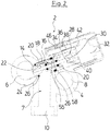
- the Fig. 1 and 2 show a first embodiment of such a hydraulic valve 2.
- the valve has a valve housing 4, which may be made for example as an injection molded part made of plastic.
- the valve housing 4 defines in its interior a first flow channel 6 and a second flow channel 8.
- the flow channels 6 and 8 are formed as straight channels which extend side by side, parallel to each other in this example, from a first to a second opposite end of the valve housing 4 ,
- a first hydraulic port 10 branches off from the first flow channel 6, and a second hydraulic port 12 branches off from the second flow channel 8.
- the connection from the second flow channel 8 to the second hydraulic port 12 is formed with a fixed unchangeable cross section, while in the connection of the first flow path 6 to the first hydraulic port 10, a valve element 14 is located.
- connection from the first flow channel 6 to the first hydraulic port 10 forms a first flow path 7, while the connection from the second flow channel 8 to the second hydraulic port 12 forms a second flow path 9.
- the valve element 14 is, as described below, movable to regulate the flow cross-section through the first flow path 7 to the first hydraulic port 10 and preferably completely close.
- the second flow channel and the second flow path 9 preferably form a flow, while the first flow channel and the first flow path 7 form a return.
- the return of a load circuit is correspondingly connected to the first hydraulic connection 10, while the flow of the load circuit is connected to the second hydraulic connection 12.
- the cross section in the return from the first hydraulic port into the first flow channel 6 through the valve element 14 is adjustable.
- valve element 14 is located on a valve insert 16, which is inserted into a valve seat 18 in the valve housing 4.
- the valve receptacle 18 is open to the outside, so that the valve insert 16 inserted from the outside into the valve housing 4 and from this, for example, for maintenance purposes, can also be removed again.
- the valve insert 16 has a substantially tubular carrier element 20, in which a spindle drive 22 is mounted as part of the valve core 16.
- a spindle drive 22 is mounted as part of the valve core 16.
- a valve seat 24 against which the valve member 14 seals and from which the valve member 14 can be linearly moved to open the flow passage.
- the valve insert 16 is sealed with two O-rings 26 with respect to the inner wall of the valve seat 18, wherein the first flow path 7 extends through a region between the two O-rings 26.
- the tubular support element 20 has an opening, so that a flow passage is formed to the valve seat 24.
- valve insert 16 At its end facing away from the valve element 14, the valve insert 16 has a coupling 28, via which the spindle 30 is coupled to a drive motor 32.
- the valve housing 4 also has an electronics receiving space 34, which is closed at its top by a removable cover 36. Inside the electronics receiving space 34 under the cover 36, a circuit board 38 is arranged, which carries electrical and electronic components for controlling or regulating the drive motor 32. For this purpose, the printed circuit board 38 is connected via a connecting plug 40 to a connecting element 42 of the drive motor 32. Furthermore, the printed circuit board 38 has electrical connections 44 for electrical connection and for data communication with an external control device. In this case, the electrical connections 44 are preferably designed for connection to the electrical connections 44 of a further valve 2.
- an infrared temperature sensor 46 is arranged on the printed circuit board 38. This is directed so that it looks towards the bottom of the electronics receiving space 34 and the valve seat 18 located therebelow.
- the carrier element 20 of the valve core 16 is preferably made of metal, for example brass, and in direct contact with the medium, in particular water, which flows through the first hydraulic port 10 and the gap between valve element 14 and valve seat 24 in the first flow path 7. As a result, the temperature of this medium is transferred to the carrier element 20.
- the carrier element 20 is in its dry region, that is in a region outside the O-rings 26 on a side facing away from the valve element 14 in contact with a bow-shaped heat conductor 48.
- This heat conductor 48th is also made of metal, preferably formed of brass and lies with its two free legs 50 at two diametrically opposed contact surfaces 52 on the outside of the support member 20 heat-conducting.
- the carrier element 20 is formed in two parts, but it is to be understood that the carrier element 20 could also be formed in one piece or from more than two parts.
- all parts of the carrier element 20 are thermally conductive and thermally conductive in connection with each other, so that the temperature of the medium, which flows the first flow path 7 in the interior of the support member 20, is transmitted to the contact surfaces 52 out. From the contact surfaces 52, the heat is transferred to the legs 50 of the heat conductor 48th
- the free legs 50 of the heat conductor 48 extend through holes 54 in the wall 56, which separates the electronics receiving space 34 of the valve seat 18.
- the wall 56 forms the bottom of the electronics receiving space 34.
- the temperature sensor 46 is outside the wet Area of the valve protected inside the electronics receiving space 34th
- Fig. 3 is different from the one based on Fig. 1 and 2 described embodiment in that the second flow channel 8 and the associated second hydraulic port 12 omitted. All other parts are designed in the same way, so that reference is made to the preceding description.
- a valve 2 ' as it is in Fig. 3 is shown, for example, in the return of a heating or load circuit, while the flow can be performed separately through a separate distributor.
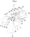
- Fig. 4 shows a third preferred embodiment, in which the valve 2 shown "similar to the valve according to Fig. 1 and 2 is trained.
- the window 60 may be formed as an opening in the wall 56, but also be sealed with a transparent material, such as glass or a transparent plastic, the material of the window 60 is then transparent to the wavelengths to be detected, in particular infrared radiation.
- the support member 20 could also be shaped to extend through the wall 56.
- Such a carrier element For example, could be poured directly into the wall 56.
- the carrier element 20 of the valve insert 16 is made of heat-conducting metal, while the valve housing 4 is made of a poorer heat-conducting, that is thermally insulating plastic material, optionally a plastic composite material. This ensures that a heat supply and / or removal via the valve housing 4 can not substantially influence the described temperature measurement, since such a heat supply or removal via the valve housing 4 is low in comparison to the heat conduction via the valve core 16.
- Fig. 5 shows the combination of several valves 2, which lined up a hydraulic distributor, for example, form a heating and / or cooling system.
- the valves 2 are shown, but it is to be understood that in a corresponding manner, the valves 2 'or 2 "according to Fig. 3 and 4 could be strung together.
- the juxtaposed valves 2 are identical and lined up so that their respective flow channels 6 and flow channels 8 (if present) are aligned with each other, so that 6 and 8 continuous flow channels are formed by the flow channels.
- Each valve 2 serves to connect a load circuit via its first hydraulic connection 10 and its second hydraulic connection 12. In the case of the embodiment according to FIG Fig. 3 If only a first hydraulic port 10 and a first flow channel 6 were provided.
- a main module 62 which produces the supply or discharge to the first and second flow channels 6 and 8 and to a feed port 64 and a return port 66 has.
- a circulation pump unit 68 is arranged, which is preferably in the flow path from the flow port 64 to the second flow channel 8 in the valves 2, which forms the flow.
- the circulating pump unit 68 has an electronics housing 70, in which a control device for controlling the circulating pump unit 68 and / or for controlling the individual valves 2 is located.
- the control electronics is connected to the electrical terminals 44 of the circuit boards 38, on which the electronic components for driving the drive motor 32 of each valve 2 are located.
- the row of valves 2 is closed by a closure module 72.
- the closure module 72 in particular closes the flow channels 6 and 8 at the end of the hydraulic distributor.
Landscapes
- Engineering & Computer Science (AREA)
- General Engineering & Computer Science (AREA)
- Mechanical Engineering (AREA)
- Temperature-Responsive Valves (AREA)
- Valve Housings (AREA)
- Control Of Transmission Device (AREA)
- Indication Of The Valve Opening Or Closing Status (AREA)
Priority Applications (5)
| Application Number | Priority Date | Filing Date | Title |
|---|---|---|---|
| DK15158775.5T DK3067603T3 (da) | 2015-03-12 | 2015-03-12 | Hydraulisk ventil |
| EP15158775.5A EP3067603B1 (de) | 2015-03-12 | 2015-03-12 | Hydraulisches ventil |
| US15/066,242 US10119629B2 (en) | 2015-03-12 | 2016-03-10 | Hydraulic valve |
| CN201610137873.6A CN105972304B (zh) | 2015-03-12 | 2016-03-11 | 液压阀 |
| RU2016108664A RU2645389C2 (ru) | 2015-03-12 | 2016-03-11 | Гидравлический клапан |
Applications Claiming Priority (1)
| Application Number | Priority Date | Filing Date | Title |
|---|---|---|---|
| EP15158775.5A EP3067603B1 (de) | 2015-03-12 | 2015-03-12 | Hydraulisches ventil |
Publications (2)
| Publication Number | Publication Date |
|---|---|
| EP3067603A1 EP3067603A1 (de) | 2016-09-14 |
| EP3067603B1 true EP3067603B1 (de) | 2019-04-24 |
Family
ID=52684054
Family Applications (1)
| Application Number | Title | Priority Date | Filing Date |
|---|---|---|---|
| EP15158775.5A Active EP3067603B1 (de) | 2015-03-12 | 2015-03-12 | Hydraulisches ventil |
Country Status (5)
| Country | Link |
|---|---|
| US (1) | US10119629B2 (da) |
| EP (1) | EP3067603B1 (da) |
| CN (1) | CN105972304B (da) |
| DK (1) | DK3067603T3 (da) |
| RU (1) | RU2645389C2 (da) |
Families Citing this family (2)
| Publication number | Priority date | Publication date | Assignee | Title |
|---|---|---|---|---|
| US10151405B1 (en) * | 2012-11-09 | 2018-12-11 | Praxair Technology, Inc. | Valve integrated pressure regulator with shroud and digital display for gas cylinders |
| DE102020109767A1 (de) * | 2020-04-08 | 2021-10-14 | Grohe Ag | Anschlusskörper für einen Unterputzeinbaukörper |
Family Cites Families (7)
| Publication number | Priority date | Publication date | Assignee | Title |
|---|---|---|---|---|
| SU932059A1 (ru) * | 1980-07-09 | 1982-05-30 | Всесоюзное Научно-Производственное Объединение "Радуга" | Гидравлический клапан |
| FR2719101B1 (fr) * | 1994-04-25 | 1996-06-28 | Chaffoteaux Et Maury | Perfectionnements aux vannes à trois voies à commande électrique. |
| DE20103992U1 (de) * | 2001-03-07 | 2001-05-31 | Grundfos A/S, Bjerringbro | Ventileinsatz für ein Dreiwege-Sitzventil zum Umschalten zwischen zwei Warmwasserkreisen einer Heizungsanlage mit einer Kreiselpumpe |
| EP1367306A1 (de) * | 2002-05-31 | 2003-12-03 | Grundfos a/s | Ventileinsatz |
| US6979503B2 (en) * | 2003-04-04 | 2005-12-27 | Texaco Inc. | Method and apparatus for burst disk identification |
| US8000909B2 (en) * | 2009-05-27 | 2011-08-16 | Dresser, Inc. | System and method for monitoring and controlling pressure relief valve performance |
| US9458612B2 (en) * | 2013-03-15 | 2016-10-04 | Delta Faucet Company | Integrated solenoid valve for an electronic faucet |
-
2015
- 2015-03-12 DK DK15158775.5T patent/DK3067603T3/da active
- 2015-03-12 EP EP15158775.5A patent/EP3067603B1/de active Active
-
2016
- 2016-03-10 US US15/066,242 patent/US10119629B2/en active Active
- 2016-03-11 CN CN201610137873.6A patent/CN105972304B/zh not_active Expired - Fee Related
- 2016-03-11 RU RU2016108664A patent/RU2645389C2/ru active
Non-Patent Citations (1)
| Title |
|---|
| None * |
Also Published As
| Publication number | Publication date |
|---|---|
| DK3067603T3 (da) | 2019-07-29 |
| RU2645389C2 (ru) | 2018-02-21 |
| EP3067603A1 (de) | 2016-09-14 |
| US10119629B2 (en) | 2018-11-06 |
| RU2016108664A (ru) | 2017-09-14 |
| CN105972304A (zh) | 2016-09-28 |
| CN105972304B (zh) | 2019-02-05 |
| US20160265689A1 (en) | 2016-09-15 |
Similar Documents
| Publication | Publication Date | Title |
|---|---|---|
| DE60319637T2 (de) | Mit Gewinde versehenes abnehmbares Heizelement für eine Heisskanal-Düse | |
| EP2312224B1 (de) | Wärmepumpe mit einem Hydraulikmodul | |
| EP1223017B1 (de) | Heisskanaldüse | |
| EP2440006B1 (de) | Elektrische Heizvorrichtung | |
| EP1101519A1 (de) | Kraftstofffilter | |
| DE102009038978A1 (de) | Vorrichtung zum Erwärmen von Flüssigkeiten | |
| AT510023B1 (de) | Extrusionsdüse | |
| DE102011084243A1 (de) | Mechatronisches Strömungsmessgerät | |
| WO2016030127A1 (de) | Temperiereinrichtung | |
| WO2014090946A2 (de) | Aktuator | |
| DE102012206495B4 (de) | Anordnung und Verfahren zur Temperierung eines Akkumulators | |
| DE202016107242U1 (de) | Sensoreinrichtung zur Bestimmung eines Massenstroms eines flüssigen Heißschmelzklebstoffes | |
| EP3067628A1 (de) | Hydraulisches ventil | |
| WO2014090953A2 (de) | Aktuator | |
| EP3067603B1 (de) | Hydraulisches ventil | |
| EP3553450B1 (de) | Wärmetauscher-einheit | |
| WO2009071157A2 (de) | Spritzgiessdüse | |
| EP2957157B1 (de) | Kombinierter kabel- und luftkanal für die schaltschrankklimatisierung sowie ein entsprechender schaltschrank | |
| DE102013207632A1 (de) | Kunststoffverarbeitungsmaschine, insbesondere Spritzgießmaschine mit einer im Bereich der Einfüllzone angeordneten Temperiereinrichtung | |
| EP3394695A1 (de) | Aktuatoreinheit sowie baugruppeneinheit mit zumindest einer solchen aktuatoreinheit und zumindest einer massenstromregel- oder ventileinheit | |
| EP1884723B1 (de) | Baueinheit | |
| DE10203239A1 (de) | Kühlbaustein | |
| DE20310275U1 (de) | Verteilereinheit für flüssige Temperiermedien, insbesondere von Temperiersystemen für Spritzgießwerkzeuge | |
| DE9411682U1 (de) | Vorrichtung zur Isolierung von Komponenten eines Wärme- oder Kältekreislaufes | |
| EP3818922A1 (de) | Kühlvorrichtung für ein endoskop oder exoskop |
Legal Events
| Date | Code | Title | Description |
|---|---|---|---|
| PUAI | Public reference made under article 153(3) epc to a published international application that has entered the european phase |
Free format text: ORIGINAL CODE: 0009012 |
|
| AK | Designated contracting states |
Kind code of ref document: A1 Designated state(s): AL AT BE BG CH CY CZ DE DK EE ES FI FR GB GR HR HU IE IS IT LI LT LU LV MC MK MT NL NO PL PT RO RS SE SI SK SM TR |
|
| AX | Request for extension of the european patent |
Extension state: BA ME |
|
| STAA | Information on the status of an ep patent application or granted ep patent |
Free format text: STATUS: REQUEST FOR EXAMINATION WAS MADE |
|
| 17P | Request for examination filed |
Effective date: 20170214 |
|
| RBV | Designated contracting states (corrected) |
Designated state(s): AL AT BE BG CH CY CZ DE DK EE ES FI FR GB GR HR HU IE IS IT LI LT LU LV MC MK MT NL NO PL PT RO RS SE SI SK SM TR |
|
| GRAP | Despatch of communication of intention to grant a patent |
Free format text: ORIGINAL CODE: EPIDOSNIGR1 |
|
| STAA | Information on the status of an ep patent application or granted ep patent |
Free format text: STATUS: GRANT OF PATENT IS INTENDED |
|
| INTG | Intention to grant announced |
Effective date: 20181019 |
|
| GRAS | Grant fee paid |
Free format text: ORIGINAL CODE: EPIDOSNIGR3 |
|
| GRAJ | Information related to disapproval of communication of intention to grant by the applicant or resumption of examination proceedings by the epo deleted |
Free format text: ORIGINAL CODE: EPIDOSDIGR1 |
|
| GRAL | Information related to payment of fee for publishing/printing deleted |
Free format text: ORIGINAL CODE: EPIDOSDIGR3 |
|
| STAA | Information on the status of an ep patent application or granted ep patent |
Free format text: STATUS: REQUEST FOR EXAMINATION WAS MADE |
|
| GRAR | Information related to intention to grant a patent recorded |
Free format text: ORIGINAL CODE: EPIDOSNIGR71 |
|
| STAA | Information on the status of an ep patent application or granted ep patent |
Free format text: STATUS: GRANT OF PATENT IS INTENDED |
|
| GRAA | (expected) grant |
Free format text: ORIGINAL CODE: 0009210 |
|
| STAA | Information on the status of an ep patent application or granted ep patent |
Free format text: STATUS: THE PATENT HAS BEEN GRANTED |
|
| INTC | Intention to grant announced (deleted) | ||
| INTG | Intention to grant announced |
Effective date: 20190312 |
|
| AK | Designated contracting states |
Kind code of ref document: B1 Designated state(s): AL AT BE BG CH CY CZ DE DK EE ES FI FR GB GR HR HU IE IS IT LI LT LU LV MC MK MT NL NO PL PT RO RS SE SI SK SM TR |
|
| REG | Reference to a national code |
Ref country code: GB Ref legal event code: FG4D Free format text: NOT ENGLISH |
|
| REG | Reference to a national code |
Ref country code: CH Ref legal event code: EP |
|
| REG | Reference to a national code |
Ref country code: AT Ref legal event code: REF Ref document number: 1124546 Country of ref document: AT Kind code of ref document: T Effective date: 20190515 Ref country code: IE Ref legal event code: FG4D Free format text: LANGUAGE OF EP DOCUMENT: GERMAN |
|
| REG | Reference to a national code |
Ref country code: DE Ref legal event code: R096 Ref document number: 502015008768 Country of ref document: DE |
|
| REG | Reference to a national code |
Ref country code: DK Ref legal event code: T3 Effective date: 20190724 |
|
| REG | Reference to a national code |
Ref country code: NL Ref legal event code: FP |
|
| REG | Reference to a national code |
Ref country code: LT Ref legal event code: MG4D |
|
| PG25 | Lapsed in a contracting state [announced via postgrant information from national office to epo] |
Ref country code: HR Free format text: LAPSE BECAUSE OF FAILURE TO SUBMIT A TRANSLATION OF THE DESCRIPTION OR TO PAY THE FEE WITHIN THE PRESCRIBED TIME-LIMIT Effective date: 20190424 Ref country code: SE Free format text: LAPSE BECAUSE OF FAILURE TO SUBMIT A TRANSLATION OF THE DESCRIPTION OR TO PAY THE FEE WITHIN THE PRESCRIBED TIME-LIMIT Effective date: 20190424 Ref country code: NO Free format text: LAPSE BECAUSE OF FAILURE TO SUBMIT A TRANSLATION OF THE DESCRIPTION OR TO PAY THE FEE WITHIN THE PRESCRIBED TIME-LIMIT Effective date: 20190724 Ref country code: PT Free format text: LAPSE BECAUSE OF FAILURE TO SUBMIT A TRANSLATION OF THE DESCRIPTION OR TO PAY THE FEE WITHIN THE PRESCRIBED TIME-LIMIT Effective date: 20190824 Ref country code: AL Free format text: LAPSE BECAUSE OF FAILURE TO SUBMIT A TRANSLATION OF THE DESCRIPTION OR TO PAY THE FEE WITHIN THE PRESCRIBED TIME-LIMIT Effective date: 20190424 Ref country code: FI Free format text: LAPSE BECAUSE OF FAILURE TO SUBMIT A TRANSLATION OF THE DESCRIPTION OR TO PAY THE FEE WITHIN THE PRESCRIBED TIME-LIMIT Effective date: 20190424 Ref country code: LT Free format text: LAPSE BECAUSE OF FAILURE TO SUBMIT A TRANSLATION OF THE DESCRIPTION OR TO PAY THE FEE WITHIN THE PRESCRIBED TIME-LIMIT Effective date: 20190424 Ref country code: ES Free format text: LAPSE BECAUSE OF FAILURE TO SUBMIT A TRANSLATION OF THE DESCRIPTION OR TO PAY THE FEE WITHIN THE PRESCRIBED TIME-LIMIT Effective date: 20190424 |
|
| PG25 | Lapsed in a contracting state [announced via postgrant information from national office to epo] |
Ref country code: BG Free format text: LAPSE BECAUSE OF FAILURE TO SUBMIT A TRANSLATION OF THE DESCRIPTION OR TO PAY THE FEE WITHIN THE PRESCRIBED TIME-LIMIT Effective date: 20190724 Ref country code: RS Free format text: LAPSE BECAUSE OF FAILURE TO SUBMIT A TRANSLATION OF THE DESCRIPTION OR TO PAY THE FEE WITHIN THE PRESCRIBED TIME-LIMIT Effective date: 20190424 Ref country code: PL Free format text: LAPSE BECAUSE OF FAILURE TO SUBMIT A TRANSLATION OF THE DESCRIPTION OR TO PAY THE FEE WITHIN THE PRESCRIBED TIME-LIMIT Effective date: 20190424 Ref country code: GR Free format text: LAPSE BECAUSE OF FAILURE TO SUBMIT A TRANSLATION OF THE DESCRIPTION OR TO PAY THE FEE WITHIN THE PRESCRIBED TIME-LIMIT Effective date: 20190725 Ref country code: LV Free format text: LAPSE BECAUSE OF FAILURE TO SUBMIT A TRANSLATION OF THE DESCRIPTION OR TO PAY THE FEE WITHIN THE PRESCRIBED TIME-LIMIT Effective date: 20190424 |
|
| PG25 | Lapsed in a contracting state [announced via postgrant information from national office to epo] |
Ref country code: IS Free format text: LAPSE BECAUSE OF FAILURE TO SUBMIT A TRANSLATION OF THE DESCRIPTION OR TO PAY THE FEE WITHIN THE PRESCRIBED TIME-LIMIT Effective date: 20190824 |
|
| REG | Reference to a national code |
Ref country code: DE Ref legal event code: R097 Ref document number: 502015008768 Country of ref document: DE |
|
| PG25 | Lapsed in a contracting state [announced via postgrant information from national office to epo] |
Ref country code: RO Free format text: LAPSE BECAUSE OF FAILURE TO SUBMIT A TRANSLATION OF THE DESCRIPTION OR TO PAY THE FEE WITHIN THE PRESCRIBED TIME-LIMIT Effective date: 20190424 Ref country code: EE Free format text: LAPSE BECAUSE OF FAILURE TO SUBMIT A TRANSLATION OF THE DESCRIPTION OR TO PAY THE FEE WITHIN THE PRESCRIBED TIME-LIMIT Effective date: 20190424 Ref country code: CZ Free format text: LAPSE BECAUSE OF FAILURE TO SUBMIT A TRANSLATION OF THE DESCRIPTION OR TO PAY THE FEE WITHIN THE PRESCRIBED TIME-LIMIT Effective date: 20190424 Ref country code: SK Free format text: LAPSE BECAUSE OF FAILURE TO SUBMIT A TRANSLATION OF THE DESCRIPTION OR TO PAY THE FEE WITHIN THE PRESCRIBED TIME-LIMIT Effective date: 20190424 |
|
| PG25 | Lapsed in a contracting state [announced via postgrant information from national office to epo] |
Ref country code: SM Free format text: LAPSE BECAUSE OF FAILURE TO SUBMIT A TRANSLATION OF THE DESCRIPTION OR TO PAY THE FEE WITHIN THE PRESCRIBED TIME-LIMIT Effective date: 20190424 Ref country code: IT Free format text: LAPSE BECAUSE OF FAILURE TO SUBMIT A TRANSLATION OF THE DESCRIPTION OR TO PAY THE FEE WITHIN THE PRESCRIBED TIME-LIMIT Effective date: 20190424 |
|
| PLBE | No opposition filed within time limit |
Free format text: ORIGINAL CODE: 0009261 |
|
| STAA | Information on the status of an ep patent application or granted ep patent |
Free format text: STATUS: NO OPPOSITION FILED WITHIN TIME LIMIT |
|
| PG25 | Lapsed in a contracting state [announced via postgrant information from national office to epo] |
Ref country code: TR Free format text: LAPSE BECAUSE OF FAILURE TO SUBMIT A TRANSLATION OF THE DESCRIPTION OR TO PAY THE FEE WITHIN THE PRESCRIBED TIME-LIMIT Effective date: 20190424 |
|
| 26N | No opposition filed |
Effective date: 20200127 |
|
| PG25 | Lapsed in a contracting state [announced via postgrant information from national office to epo] |
Ref country code: SI Free format text: LAPSE BECAUSE OF FAILURE TO SUBMIT A TRANSLATION OF THE DESCRIPTION OR TO PAY THE FEE WITHIN THE PRESCRIBED TIME-LIMIT Effective date: 20190424 |
|
| PG25 | Lapsed in a contracting state [announced via postgrant information from national office to epo] |
Ref country code: MC Free format text: LAPSE BECAUSE OF FAILURE TO SUBMIT A TRANSLATION OF THE DESCRIPTION OR TO PAY THE FEE WITHIN THE PRESCRIBED TIME-LIMIT Effective date: 20190424 |
|
| REG | Reference to a national code |
Ref country code: CH Ref legal event code: PL |
|
| REG | Reference to a national code |
Ref country code: BE Ref legal event code: MM Effective date: 20200331 |
|
| PG25 | Lapsed in a contracting state [announced via postgrant information from national office to epo] |
Ref country code: LU Free format text: LAPSE BECAUSE OF NON-PAYMENT OF DUE FEES Effective date: 20200312 |
|
| PG25 | Lapsed in a contracting state [announced via postgrant information from national office to epo] |
Ref country code: IE Free format text: LAPSE BECAUSE OF NON-PAYMENT OF DUE FEES Effective date: 20200312 Ref country code: CH Free format text: LAPSE BECAUSE OF NON-PAYMENT OF DUE FEES Effective date: 20200331 Ref country code: LI Free format text: LAPSE BECAUSE OF NON-PAYMENT OF DUE FEES Effective date: 20200331 |
|
| PG25 | Lapsed in a contracting state [announced via postgrant information from national office to epo] |
Ref country code: BE Free format text: LAPSE BECAUSE OF NON-PAYMENT OF DUE FEES Effective date: 20200331 |
|
| REG | Reference to a national code |
Ref country code: AT Ref legal event code: MM01 Ref document number: 1124546 Country of ref document: AT Kind code of ref document: T Effective date: 20200312 |
|
| PG25 | Lapsed in a contracting state [announced via postgrant information from national office to epo] |
Ref country code: AT Free format text: LAPSE BECAUSE OF NON-PAYMENT OF DUE FEES Effective date: 20200312 |
|
| PG25 | Lapsed in a contracting state [announced via postgrant information from national office to epo] |
Ref country code: MT Free format text: LAPSE BECAUSE OF FAILURE TO SUBMIT A TRANSLATION OF THE DESCRIPTION OR TO PAY THE FEE WITHIN THE PRESCRIBED TIME-LIMIT Effective date: 20190424 Ref country code: CY Free format text: LAPSE BECAUSE OF FAILURE TO SUBMIT A TRANSLATION OF THE DESCRIPTION OR TO PAY THE FEE WITHIN THE PRESCRIBED TIME-LIMIT Effective date: 20190424 |
|
| PG25 | Lapsed in a contracting state [announced via postgrant information from national office to epo] |
Ref country code: MK Free format text: LAPSE BECAUSE OF FAILURE TO SUBMIT A TRANSLATION OF THE DESCRIPTION OR TO PAY THE FEE WITHIN THE PRESCRIBED TIME-LIMIT Effective date: 20190424 |
|
| REG | Reference to a national code |
Ref country code: DE Ref legal event code: R082 Ref document number: 502015008768 Country of ref document: DE |
|
| PGFP | Annual fee paid to national office [announced via postgrant information from national office to epo] |
Ref country code: FR Payment date: 20230324 Year of fee payment: 9 Ref country code: DK Payment date: 20230323 Year of fee payment: 9 |
|
| PGFP | Annual fee paid to national office [announced via postgrant information from national office to epo] |
Ref country code: GB Payment date: 20230322 Year of fee payment: 9 Ref country code: DE Payment date: 20230321 Year of fee payment: 9 |
|
| PGFP | Annual fee paid to national office [announced via postgrant information from national office to epo] |
Ref country code: NL Payment date: 20230321 Year of fee payment: 9 |
|
| REG | Reference to a national code |
Ref country code: DE Ref legal event code: R119 Ref document number: 502015008768 Country of ref document: DE |
|
| REG | Reference to a national code |
Ref country code: DK Ref legal event code: EBP Effective date: 20240331 |
|
| REG | Reference to a national code |
Ref country code: NL Ref legal event code: MM Effective date: 20240401 |
|
| GBPC | Gb: european patent ceased through non-payment of renewal fee |
Effective date: 20240312 |
|
| PG25 | Lapsed in a contracting state [announced via postgrant information from national office to epo] |
Ref country code: NL Free format text: LAPSE BECAUSE OF NON-PAYMENT OF DUE FEES Effective date: 20240401 |
|
| PG25 | Lapsed in a contracting state [announced via postgrant information from national office to epo] |
Ref country code: NL Free format text: LAPSE BECAUSE OF NON-PAYMENT OF DUE FEES Effective date: 20240401 |
|
| PG25 | Lapsed in a contracting state [announced via postgrant information from national office to epo] |
Ref country code: DE Free format text: LAPSE BECAUSE OF NON-PAYMENT OF DUE FEES Effective date: 20241001 |
|
| PG25 | Lapsed in a contracting state [announced via postgrant information from national office to epo] |
Ref country code: GB Free format text: LAPSE BECAUSE OF NON-PAYMENT OF DUE FEES Effective date: 20240312 |
|
| PG25 | Lapsed in a contracting state [announced via postgrant information from national office to epo] |
Ref country code: FR Free format text: LAPSE BECAUSE OF NON-PAYMENT OF DUE FEES Effective date: 20240331 |
|
| PG25 | Lapsed in a contracting state [announced via postgrant information from national office to epo] |
Ref country code: GB Free format text: LAPSE BECAUSE OF NON-PAYMENT OF DUE FEES Effective date: 20240312 Ref country code: FR Free format text: LAPSE BECAUSE OF NON-PAYMENT OF DUE FEES Effective date: 20240331 Ref country code: DE Free format text: LAPSE BECAUSE OF NON-PAYMENT OF DUE FEES Effective date: 20241001 |
|
| PG25 | Lapsed in a contracting state [announced via postgrant information from national office to epo] |
Ref country code: DK Free format text: LAPSE BECAUSE OF NON-PAYMENT OF DUE FEES Effective date: 20240331 |