EP3067683A1 - Dispositif et procédé de détection d'état de roulement - Google Patents
Dispositif et procédé de détection d'état de roulement Download PDFInfo
- Publication number
- EP3067683A1 EP3067683A1 EP14860113.1A EP14860113A EP3067683A1 EP 3067683 A1 EP3067683 A1 EP 3067683A1 EP 14860113 A EP14860113 A EP 14860113A EP 3067683 A1 EP3067683 A1 EP 3067683A1
- Authority
- EP
- European Patent Office
- Prior art keywords
- bearing
- state
- state detection
- detection device
- actual
- Prior art date
- Legal status (The legal status is an assumption and is not a legal conclusion. Google has not performed a legal analysis and makes no representation as to the accuracy of the status listed.)
- Granted
Links
Images


Classifications
-
- G—PHYSICS
- G01—MEASURING; TESTING
- G01M—TESTING STATIC OR DYNAMIC BALANCE OF MACHINES OR STRUCTURES; TESTING OF STRUCTURES OR APPARATUS, NOT OTHERWISE PROVIDED FOR
- G01M13/00—Testing of machine parts
- G01M13/04—Bearings
- G01M13/045—Acoustic or vibration analysis
-
- B—PERFORMING OPERATIONS; TRANSPORTING
- B61—RAILWAYS
- B61C—LOCOMOTIVES; MOTOR RAILCARS
- B61C9/00—Locomotives or motor railcars characterised by the type of transmission system used; Transmission systems specially adapted for locomotives or motor railcars
- B61C9/38—Transmission systems in or for locomotives or motor railcars with electric motor propulsion
- B61C9/48—Transmission systems in or for locomotives or motor railcars with electric motor propulsion with motors supported on vehicle frames and driving axles, e.g. axle or nose suspension
-
- B—PERFORMING OPERATIONS; TRANSPORTING
- B61—RAILWAYS
- B61K—AUXILIARY EQUIPMENT SPECIALLY ADAPTED FOR RAILWAYS, NOT OTHERWISE PROVIDED FOR
- B61K9/00—Railway vehicle profile gauges; Detecting or indicating overheating of components; Apparatus on locomotives or cars to indicate bad track sections; General design of track recording vehicles
-
- F—MECHANICAL ENGINEERING; LIGHTING; HEATING; WEAPONS; BLASTING
- F16—ENGINEERING ELEMENTS AND UNITS; GENERAL MEASURES FOR PRODUCING AND MAINTAINING EFFECTIVE FUNCTIONING OF MACHINES OR INSTALLATIONS; THERMAL INSULATION IN GENERAL
- F16C—SHAFTS; FLEXIBLE SHAFTS; ELEMENTS OR CRANKSHAFT MECHANISMS; ROTARY BODIES OTHER THAN GEARING ELEMENTS; BEARINGS
- F16C19/00—Bearings with rolling contact, for exclusively rotary movement
- F16C19/52—Bearings with rolling contact, for exclusively rotary movement with devices affected by abnormal or undesired conditions
-
- G—PHYSICS
- G01—MEASURING; TESTING
- G01M—TESTING STATIC OR DYNAMIC BALANCE OF MACHINES OR STRUCTURES; TESTING OF STRUCTURES OR APPARATUS, NOT OTHERWISE PROVIDED FOR
- G01M13/00—Testing of machine parts
- G01M13/04—Bearings
-
- G—PHYSICS
- G01—MEASURING; TESTING
- G01M—TESTING STATIC OR DYNAMIC BALANCE OF MACHINES OR STRUCTURES; TESTING OF STRUCTURES OR APPARATUS, NOT OTHERWISE PROVIDED FOR
- G01M17/00—Testing of vehicles
- G01M17/08—Railway vehicles
- G01M17/10—Suspensions, axles or wheels
-
- F—MECHANICAL ENGINEERING; LIGHTING; HEATING; WEAPONS; BLASTING
- F16—ENGINEERING ELEMENTS AND UNITS; GENERAL MEASURES FOR PRODUCING AND MAINTAINING EFFECTIVE FUNCTIONING OF MACHINES OR INSTALLATIONS; THERMAL INSULATION IN GENERAL
- F16C—SHAFTS; FLEXIBLE SHAFTS; ELEMENTS OR CRANKSHAFT MECHANISMS; ROTARY BODIES OTHER THAN GEARING ELEMENTS; BEARINGS
- F16C2326/00—Articles relating to transporting
- F16C2326/10—Railway vehicles
-
- Y—GENERAL TAGGING OF NEW TECHNOLOGICAL DEVELOPMENTS; GENERAL TAGGING OF CROSS-SECTIONAL TECHNOLOGIES SPANNING OVER SEVERAL SECTIONS OF THE IPC; TECHNICAL SUBJECTS COVERED BY FORMER USPC CROSS-REFERENCE ART COLLECTIONS [XRACs] AND DIGESTS
- Y02—TECHNOLOGIES OR APPLICATIONS FOR MITIGATION OR ADAPTATION AGAINST CLIMATE CHANGE
- Y02T—CLIMATE CHANGE MITIGATION TECHNOLOGIES RELATED TO TRANSPORTATION
- Y02T30/00—Transportation of goods or passengers via railways, e.g. energy recovery or reducing air resistance
Definitions
- the present invention relates to a bearing state detection device and a bearing state detection method configured to detect a state of a bearing of a gear device configuring a truck of a railroad vehicle.
- a rotation device for vibration detection of abnormality in a bearing of a truck of a railroad vehicle disclosed in Patent Document 1 is a device for detecting, with high precision, abnormality in a journal bearing attached to a wheel axle of the truck of the railroad vehicle or a bearing of a reduction gear device and the like in a non-disassembling manner by vibration inspection.
- the wheel axle is rotated at load conditions close to an actual traveling, and damage vibration generated by a roller in the journal bearing or the reduction gear device is detected by a vibration measurement sensor, so that the vibration of the bearing is measured.
- the device disclosed in Patent Document 1 is configured to detect the damage vibration by rotating the wheel axle of the truck of the railroad vehicle at the load conditions close to the actual traveling.
- the railroad vehicle travels while additionally receiving loads which are not reproduced in the device of Patent Document 1. That is, the loads which are to be applied to the railroad vehicle during the actual traveling includes various parameters including environmental factors such as wind, temperature and the like and factors relating to a railway track. Therefore, according to the device of Patent Document 1, even when rotating the wheel axle at the load conditions close to the actual traveling, since the damage vibration based on the loads which are to be actually applied to the bearing during the actual traveling is not detected, an actual state of the bearing may not be detected depending on a location or extent of the damage to the bearing.
- An object of the present invention is to provide a bearing state detection device and a bearing state detection method capable of detecting, with high precision, an actual state of damage to a bearing of a gear device configuring a truck of a railroad vehicle.
- the bearing state detection device and the bearing state detection method of the present invention it is possible to detect, with high precision, the actual state of the damage to the bearing of the gear device configuring the truck of the railroad vehicle.
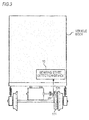
- the bearing state detection device which is to be described later is a device configured to detect a state of a bearing of a gear device configuring a truck of a railroad vehicle and is to be mounted on the railroad vehicle.
- FIG. 1 is a schematic view of a truck of a railroad vehicle as seen from a front direction.
- FIG. 2 is a schematic view of the truck of the railroad vehicle as seen from below.
- the truck of the railroad vehicle mainly includes a gear device (also referred to as "drive device") 111, an electric motor 113, a truck frame 115, ajoint 117, an axle 119, wheels 121 and bearings 123.
- gear device also referred to as "drive device”
- the gear device 111 configured to function as a speed reducer has a small gear (also referred to as "pinion") 131 and a large gear 133 configured to mesh with each other.
- the small gear 131 and the large gear 133 are respectively spur gears.
- the gear device 111 has bearings 135 configured to rotatably support a shaft of the small gear 131. By the bearings 135, the shaft of the small gear 131 is prevented from whirling.
- a housing of the bearing 135 is fixed to a housing of the gear device 111.
- the electric motor 113 which is a driving source of the railroad vehicle, is fixed to the truck frame 115.
- a rotary shaft 125 of the electric motor 113 is coupled to the shaft of the small gear 131 of the gear device 111 via the joint 117. Therefore, a rotational force of the electric motor 113 is transmitted to the small gear 131 of the gear device 111 via the joint 117.
- the large gear 133 of the gear device 111 is fitted coaxially with the axle 119.
- the wheels 121 are also fitted to the axle 119. Therefore, the rotational force transmitted from the electric motor 113 to the small gear 131 of the gear device 111 is transmitted to the wheels 121 via the large gear 133 and the axle 119.
- the bearing 123 is to rotatably support the axle 119.
- a shaft spring 127 for absorbing vibrations (hereinafter, referred to as "traveling vibrations"), which are generated as the railroad vehicle travels, is mounted between the bearing 123 and the truck frame 115.
- traveling vibrations which are generated as the railroad vehicle travels.
- the traveling vibrations generated during the actual traveling of the railroad vehicle include various factors like environmental factors such as winds to blow to the railroad vehicle and factors relating to a railway track.
- the loads are continuously applied to the bearing 135, damages such as creep, seizing of a collar, pocket wear and the like may be caused to the bearing 135.
- the bearing 135 is damaged, parameters such as vibration, temperature, torque, displacement, Acoustic Emission (AE), rotation speed and the like and temporal changes thereof in the small gear 131 of the gear device 111 appear as differences from those at a normal state.
- a bearing state detection device of the embodiment is mounted to the railroad vehicle and is configured to detect an actual state relating to the damage to the bearing 135 based on a change of a parameter corresponding to the damage to the bearing 135 during the actual traveling of the railroad vehicle.
- a bearing state detection device 10 of the embodiment is provided in the railroad vehicle including the truck.
- the bearing state detection device 10 is input with a measured value of a sensor 20 configured to measure at least one of parameters such as vibration, temperature, torque, displacement, Acoustic Emission (AE), rotation speed and the like.
- the sensor 20 is provided in the vicinity of the bearing 135 of the gear device 111.
- the sensor 20 may be a microphone (not shown) configured to collect sounds in the vicinity of the bearing 135 of the gear device 111.
- the transmission of information from the sensor 20 to the bearing state detection device 10 may be performed by wired or wireless communication.
- the damage to the bearing 135 is caused by creep, seizing of a collar, pocket wear, and the like.
- creep occurs, an end surface of the housing is worn, so that a bearing clearance increases and whirling of the shaft increases. Thereafter, when a rolling element collides more frequently in a pocket, a holder is ruptured.
- the bearing clearance increases and the whirling of the shaft increases.
- the holder is ruptured.
- the pocket wear progresses, the whirling of the holder increases, and when the collision frequency of the rolling element in the pocket increases, the holder is ruptured.
- the bearing 135 is finally damaged and the rolling element is separated, for example.
- the bearing 135 undergoes stages from the damage to the rupture. However, the parameters indicated by the information from the sensor 20 are changed depending on the contents or extents thereof.
- the sensor 20 measures torque of the bearing 135. As shown by test data of FIG. 4 , when oil supply to the bearing 135 is stopped at a state where the rotation speed of the bearing 135 is kept at a constant value, the measured value of the sensor 20 once decreases and then sharply increases, and the seizing occurs in the bearing 135. Also, in a test example of FIG. 5 , the sensor 20 measures temperatures of the bearing 135. As shown by test data of FIG. 5 , when the oil supply to the bearing 135 is stopped at a state where the rotation speed of the bearing 135 is kept at a constant value, the measured value of the sensor 20 increases with a characteristic curve, and the seizing occurs in the bearing 135.
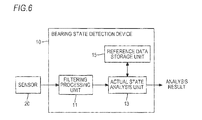
- FIG. 6 is a block diagram showing an internal configuration of the bearing state detection device 10 according to an embodiment. As shown in FIG. 6 , the bearing state detection device 10 has a filtering processing unit 11, an actual state analysis unit 13 and a reference data storage unit 15.
- the filtering processing unit 11 is configured to remove parameters except for parameters relating to the bearing 135 by filtering the measured values of the sensor 20. That is, the measured values of the sensor 20 include not only parameters relating to states of the bearing 135 but also parameters relating to the other constitutional elements such as the electric motor 113, the axle 119 and the like. In this embodiment, the parameters relating to the constitutional elements except for the bearing 135 are removed so as to detect the actual state relating to the damage to the bearing 135.
- the actual state analysis unit 1 is configured to analyze the actual state relating to the damage to the bearing 135 by analyzing the filtered measured values. Meanwhile, in the analysis processing, "ACOUS NAVI" (registered trademark) developed as a bearing abnormality sound analysis system may be used.
- the actual state analysis unit 13 is configured to store, as reference data, a result obtained by analyzing the measured values filtered at the normal state of the bearing 135 in the reference data storage unit 15 during the actual traveling of the railroad vehicle.
- the actual state analysis unit 13 is configured to compare the analysis result of the filtered measured values with reference data and determine that the bearing 135 is damaged when there is a difference between both the data.
- the actual state analysis unit 13 is configured to determine whether the bearing 135 is abnormal by comparing data (for example, effective value or frequency power spectrum), which is obtained by analyzing a vibration measurement signal obtained from the sensor 20 provided in the vicinity of the bearing 135 of the gear device 111, with the data in a predetermined frequency band, which is obtained at the normal state, during the constant speed inertia traveling of the railroad vehicle, in which the vibrations of the constitutional elements (the small gear 131 and the like) except for the bearing 135 are relatively less.
- the predetermined frequency band is characteristic frequencies of the gear device 111.
- the actual state analysis unit 13 determines that the bearing 135 is normal.
- the reference data storage unit 15 is configured to store therein the reference data obtained by analyzing the measured values filtered at the normal state of the bearing 135. In the meantime, the reference data is data obtained during the actual traveling of the railroad vehicle.
- FIG. 7 is a schematic view of the actual machine driving device testing machine 130 for verifying the effects of the bearing state detection device 10 according to the embodiment.
- the actual machine driving device testing machine 130 has a gear device (also referred to as "drive device”) 111a, a motor (an electric motor) 113a, a generator 140 and a vibration sensor 20a.
- the gear device 111a is configured to function as a speed reducer and has a small gear (also referred to as "pinion”) 131a and a large gear 133a configured to mesh with each other.
- the small gear 131a and the large gear 133a are respectively spur gears.
- the gear device 111a has two bearings 135a, 135b configured to rotatably support a shaft of the small gear 131a and two bearings 141a, 141b configured to rotatably support a shaft of the large gear 133a.
- the bearings 135a, 135b are arranged at both sides of the small gear 131a so as to sandwich the small gear therebetween, and the bearings 141a, 141 b are arranged at both sides of the large gear 133a so as to sandwich the large gear therebetween.
- a housing (not shown) of each of the bearings 135a, 135b and the bearings 141a, 141b is fixed to a housing of the gear device 111a.
- the bearings 135a, 135b By the bearings 135a, 135b, the shaft of the small gear 131a is prevented from whirling, and by the bearings 141a, 141 b, the shaft of the large gear 133a is prevented from whirling.
- a rotational force of the motor 113a is transmitted to the small gear 131a of the gear device 111a.
- the rotational force transmitted from the motor 113a to the small gear 131a is transmitted to the generator 140 via the large gear 133a. Therefore, the motor 113a operates, so that power is generated from the generator 140.
- the vibration sensor 20a is equivalent to the sensor 20, and is transmitted in the vicinity of the bearings 135a, 135b of the gear device 111a.
- the vibration sensor 20a is used to detect vibrations caused due to the seizing of collars of the bearing 135a, 135b, the pocket wear, the whirling of a holder (which is one of components of the bearing and is configured to hold a plurality of rolling elements at a constant interval), and the like.
- a measured value of the vibration sensor 20a is input to the bearing state detection device 10.
- the bearing 135b was set as a bearing of which an extent of damage was low, and the bearing 135a was set as a normal bearing. Also, the test was performed at conditions that the number of rotations was set to 5680 min -1 equivalent to 320 km/h traveling of the actual machine and the load (torque) to the bearing was set to 736 N ⁇ m. In the meantime, both the bearings 141a, 141b were all normal products.
- FIGS. 8A to 8C show vibration analysis results when damage to the bearing of the actual machine driving device testing machine 130 occurs.
- FIG. 8A shows intensities (vibration level [dB]) of the bearing 135b (the damaged product) and the bearing 135a (the normal product), and a horizontal axis indicates a frequency [Hz] and a vertical axis indicates an intensity [dB].
- FFT Fast Fourier Transform
- FIG. 8B shows respective processing (filtering processing, absolute value detection processing and envelope detection processing) of the vibration analysis.
- FIG. 8C shows a vibration analysis result of the bearing 135b (the damaged product), and a horizontal axis indicates a frequency [Hz] and a vertical axis indicates an intensity [dB].
- the characteristic frequency component "fc" which is the revolution period of the holder, appeared.
- the intensity thereof was weak and the number of the characteristic frequency components (the number of "fc") was small.
- FIG. 9 shows a relation between a position of the damage to the bearing and a specific frequency component [Hz].
- the specific frequency component [Hz] is expressed by an equation indicated by Zfi
- the specific frequency component [Hz] is expressed by an equation indicated by Zfc
- the specific frequency component [Hz] is expressed by an equation indicated by 2fb.
- Z indicates the number of the rolling elements
- fr indicates the rotation speed of the inner ring [Hz]
- fc indicates the rotation speed of the holder [Hz]
- dm indicates a pitch circle diameter
- Da indicates a diameter of the rolling element, and
- ⁇ indicates a contact angle.
- the abnormalities such as the seizing of the collar of the bearing 135b, the pocket wear of the holder of the bearing 135b, the whirling of the holder of the bearing 135b and the like could be detected by performing the vibration analysis in which the FFT vibration analysis processing, the filtering processing and the absolute value detection processing were performed and then the envelope processing was performed through the detection by the vibration sensor 20a. Also, it is possible to calculate an occurrence frequency resulting from the meshing between the small gear 131a and the large gear 133a.
- the bearing state detection device 10 of the embodiment is configured to detect the actual state of the damage to the bearing 135 by determining whether there is a change in the parameters as a result of the damage to the bearing 135, based on the information from the sensor 20 obtained during the actual traveling of the railroad vehicle.
- a sign relating to the abnormality of the bearing 135 is diagnosed, it is possible to rapidly detect an abnormal state of the bearing 135 with high precision.
- it is possible to detect a possibility of the damage before the bearing 135 reaches the rupture it is possible to take action at a stage before periodic maintenance. Therefore, it is possible to highly improve the safety and reliability of the gear device 111 including the bearing 135.
- the present invention is not limited to the configuration of the above embodiment, and any configuration can be applied inasmuch as it can implement the functions defined in the claims or the functions of the configuration of the embodiment.
Landscapes
- Engineering & Computer Science (AREA)
- Physics & Mathematics (AREA)
- Mechanical Engineering (AREA)
- General Physics & Mathematics (AREA)
- General Engineering & Computer Science (AREA)
- Acoustics & Sound (AREA)
- Chemical & Material Sciences (AREA)
- Combustion & Propulsion (AREA)
- Transportation (AREA)
- Testing Of Devices, Machine Parts, Or Other Structures Thereof (AREA)
- Rolling Contact Bearings (AREA)
Applications Claiming Priority (3)
| Application Number | Priority Date | Filing Date | Title |
|---|---|---|---|
| JP2013229107 | 2013-11-05 | ||
| JP2014221953A JP6413642B2 (ja) | 2013-11-05 | 2014-10-30 | 軸受状態検知装置及び軸受状態検知方法 |
| PCT/JP2014/079360 WO2015068737A1 (fr) | 2013-11-05 | 2014-11-05 | Dispositif et procédé de détection d'état de roulement |
Publications (3)
| Publication Number | Publication Date |
|---|---|
| EP3067683A1 true EP3067683A1 (fr) | 2016-09-14 |
| EP3067683A4 EP3067683A4 (fr) | 2016-11-02 |
| EP3067683B1 EP3067683B1 (fr) | 2019-10-09 |
Family
ID=53041514
Family Applications (1)
| Application Number | Title | Priority Date | Filing Date |
|---|---|---|---|
| EP14860113.1A Active EP3067683B1 (fr) | 2013-11-05 | 2014-11-05 | Dispositif et procédé de détection d'état de roulement |
Country Status (5)
| Country | Link |
|---|---|
| US (1) | US20160282223A1 (fr) |
| EP (1) | EP3067683B1 (fr) |
| JP (1) | JP6413642B2 (fr) |
| CN (1) | CN105765362A (fr) |
| WO (1) | WO2015068737A1 (fr) |
Cited By (1)
| Publication number | Priority date | Publication date | Assignee | Title |
|---|---|---|---|---|
| JP2015111113A (ja) * | 2013-11-05 | 2015-06-18 | 日本精工株式会社 | 軸受状態検知装置及び軸受状態検知方法 |
Families Citing this family (12)
| Publication number | Priority date | Publication date | Assignee | Title |
|---|---|---|---|---|
| US10775271B2 (en) | 2012-08-22 | 2020-09-15 | Ge Global Sourcing Llc | System for determining conicity of a wheel based on measured vibrations |
| CN107843429B (zh) * | 2016-09-19 | 2021-08-31 | 舍弗勒技术股份两合公司 | 轴承状态监测控制方法及控制装置、监测设备、监测方法 |
| EP3444585B1 (fr) * | 2017-08-17 | 2020-05-27 | ALSTOM Transport Technologies | Procédé pour déterminer l'état d'un palier, module pour déterminer l'état d'un palier, véhicule ferroviaire et système |
| JP7016298B2 (ja) * | 2018-07-11 | 2022-02-21 | 公益財団法人鉄道総合技術研究所 | 検出器 |
| JP6507297B1 (ja) * | 2018-09-07 | 2019-04-24 | オークマ株式会社 | 転がり軸受の異常診断方法及び異常診断装置、異常診断プログラム |
| JP7306968B2 (ja) * | 2019-11-06 | 2023-07-11 | 株式会社日本製鋼所 | 異常検知装置、異常検知方法及びコンピュータプログラム |
| JP7306967B2 (ja) * | 2019-11-06 | 2023-07-11 | 株式会社日本製鋼所 | 異常検知装置、異常検知方法及びコンピュータプログラム |
| JP7242518B2 (ja) * | 2019-12-16 | 2023-03-20 | 株式会社東芝 | 非破壊検査方法及び非破壊検査システム |
| JP7631996B2 (ja) * | 2021-03-31 | 2025-02-19 | 日本精工株式会社 | 軸受状態診断装置 |
| JP7584602B2 (ja) * | 2022-03-01 | 2024-11-15 | 三菱電機株式会社 | 転がり軸受の異常診断方法 |
| JP7471523B2 (ja) * | 2022-03-01 | 2024-04-19 | 三菱電機株式会社 | 転がり軸受の異常検知装置、転がり軸受の異常診断装置、及び列車異常監視システム |
| DE102023200663A1 (de) * | 2023-01-27 | 2024-08-01 | Siemens Mobility GmbH | Verfahren zur Ermittlung des Zustands einer beweglichen Komponente in einem Fahrzeug |
Family Cites Families (15)
| Publication number | Priority date | Publication date | Assignee | Title |
|---|---|---|---|---|
| JP2901666B2 (ja) | 1989-11-10 | 1999-06-07 | 光洋精工株式会社 | 鉄道車両用軸受装置の診断装置 |
| JP3284967B2 (ja) | 1998-04-23 | 2002-05-27 | 住友金属工業株式会社 | 鉄道車両用駆動装置 |
| US6967586B2 (en) * | 2000-10-20 | 2005-11-22 | Sankyo Seiki Mfg. Co., Ltd. | Bearing test method, bearing test device, bearing monitoring device and storage device |
| EP1624206B1 (fr) * | 2003-05-13 | 2010-03-17 | JTEKT Corporation | Systeme et procede de gestion pour un roulement |
| JP4427400B2 (ja) | 2004-07-05 | 2010-03-03 | 住金関西工業株式会社 | 鉄道車両台車のベアリング異常の振動検出用回転装置 |
| JP2006077938A (ja) * | 2004-09-13 | 2006-03-23 | Nsk Ltd | 異常診断装置 |
| WO2006030786A1 (fr) * | 2004-09-13 | 2006-03-23 | Nsk Ltd. | Dispositif de diagnostic d’anomalie et procede de diagnostic d’anomalie |
| JP4527585B2 (ja) * | 2005-03-30 | 2010-08-18 | 財団法人鉄道総合技術研究所 | 軸受監視システム、及び軸受監視プログラム |
| JP4802975B2 (ja) | 2006-10-30 | 2011-10-26 | 住友金属工業株式会社 | 鉄道車両用歯車装置の温度予測方法 |
| JP4997936B2 (ja) * | 2006-11-28 | 2012-08-15 | 日本精工株式会社 | 転がり軸受の異常診断装置および乗物 |
| MX2009013288A (es) * | 2007-06-04 | 2010-02-24 | Eaton Corp | Sistema y metodo para deteccion de falla de cojinete usando cancelacion de ruido de corriente del estator. |
| JP5455298B2 (ja) * | 2007-11-06 | 2014-03-26 | オークマ株式会社 | 軸受状態診断装置 |
| JP4961417B2 (ja) * | 2008-12-17 | 2012-06-27 | 株式会社テイエルブイ | 機器状態情報収集方法、及び、それに用いる機器状態情報収集キット |
| JP5725833B2 (ja) * | 2010-01-04 | 2015-05-27 | Ntn株式会社 | 転がり軸受の異常診断装置、風力発電装置および異常診断システム |
| JP6413642B2 (ja) * | 2013-11-05 | 2018-10-31 | 日本精工株式会社 | 軸受状態検知装置及び軸受状態検知方法 |
-
2014
- 2014-10-30 JP JP2014221953A patent/JP6413642B2/ja not_active Ceased
- 2014-11-05 WO PCT/JP2014/079360 patent/WO2015068737A1/fr not_active Ceased
- 2014-11-05 EP EP14860113.1A patent/EP3067683B1/fr active Active
- 2014-11-05 US US15/034,226 patent/US20160282223A1/en not_active Abandoned
- 2014-11-05 CN CN201480060682.3A patent/CN105765362A/zh active Pending
Cited By (1)
| Publication number | Priority date | Publication date | Assignee | Title |
|---|---|---|---|---|
| JP2015111113A (ja) * | 2013-11-05 | 2015-06-18 | 日本精工株式会社 | 軸受状態検知装置及び軸受状態検知方法 |
Also Published As
| Publication number | Publication date |
|---|---|
| JP2015111113A (ja) | 2015-06-18 |
| EP3067683A4 (fr) | 2016-11-02 |
| CN105765362A (zh) | 2016-07-13 |
| EP3067683B1 (fr) | 2019-10-09 |
| JP6413642B2 (ja) | 2018-10-31 |
| WO2015068737A1 (fr) | 2015-05-14 |
| US20160282223A1 (en) | 2016-09-29 |
Similar Documents
| Publication | Publication Date | Title |
|---|---|---|
| EP3067683B1 (fr) | Dispositif et procédé de détection d'état de roulement | |
| EP2522977B1 (fr) | Dispositif de diagnostic d'anomalie pour un roulement, générateur d'énergie éolienne électrique et système de diagnostic d'anomalie | |
| CN104990709B (zh) | 用于检测机车轴承故障的方法 | |
| US9459179B2 (en) | Method and device for monitoring a drive train of a wind power plant | |
| US9728016B2 (en) | Wheel monitoring system and method | |
| KR102624536B1 (ko) | 고장 진단 장치 및 이러한 고장 진단 장치를 구비하는 차량용 휠베어링 | |
| JP7027782B2 (ja) | 転がり軸受の異常診断装置 | |
| US11148689B2 (en) | Vehicle monitoring system | |
| WO2006030786A1 (fr) | Dispositif de diagnostic d’anomalie et procede de diagnostic d’anomalie | |
| EP2730898B1 (fr) | Roulement à billes, boîtier comprenant un ensemble de roulements, procédé associé et programme informatique | |
| JP2014530347A (ja) | 自動車用シャシシステムにおける構成部品の欠陥診断方法及び装置 | |
| CN105452835A (zh) | 轴承装置振动分析方法、轴承装置振动分析器以及滚动轴承状态监视系统 | |
| WO2017145687A1 (fr) | Dispositif de diagnostic d'anomalie et procédé de diagnostic d'anomalie | |
| CN109278796A (zh) | 一种车载式车轮不圆度检测系统 | |
| KR20110131411A (ko) | 허브 베어링 검사 방법 | |
| KR101495841B1 (ko) | 전동 열차의 진동 측정 장치 | |
| JP6714844B2 (ja) | 異常診断方法 | |
| CN102798413B (zh) | 一种铁道动态检测系统 | |
| TW201917282A (zh) | 風力發電系統 | |
| JP3566002B2 (ja) | 転がり軸受の診断方法および転がり軸受装置 | |
| EP3556636A2 (fr) | Système et procédé de traitement de signal de capteur | |
| KR20150044141A (ko) | 철도차량용 감속장치의 이상유무 감지장치 및 감지방법 | |
| Wei et al. | Study on wheel-flat detection method based on vehicle system acceleration measurement | |
| Vyplaven et al. | Analysis of Frequency and Time Characteristics of the Vibration Acceleration Signal of Traction Electric Motor of Motor Car | |
| JP2021018106A (ja) | 軸受異常予知装置および軸受異常予知方法 |
Legal Events
| Date | Code | Title | Description |
|---|---|---|---|
| PUAI | Public reference made under article 153(3) epc to a published international application that has entered the european phase |
Free format text: ORIGINAL CODE: 0009012 |
|
| 17P | Request for examination filed |
Effective date: 20160429 |
|
| AK | Designated contracting states |
Kind code of ref document: A1 Designated state(s): AL AT BE BG CH CY CZ DE DK EE ES FI FR GB GR HR HU IE IS IT LI LT LU LV MC MK MT NL NO PL PT RO RS SE SI SK SM TR |
|
| AX | Request for extension of the european patent |
Extension state: BA ME |
|
| A4 | Supplementary search report drawn up and despatched |
Effective date: 20160930 |
|
| RIC1 | Information provided on ipc code assigned before grant |
Ipc: G01M 99/00 20110101AFI20160926BHEP Ipc: B61C 9/38 20060101ALI20160926BHEP Ipc: F16C 19/52 20060101ALI20160926BHEP Ipc: F16C 19/00 20060101ALI20160926BHEP Ipc: F16C 41/00 20060101ALI20160926BHEP |
|
| DAX | Request for extension of the european patent (deleted) | ||
| STAA | Information on the status of an ep patent application or granted ep patent |
Free format text: STATUS: EXAMINATION IS IN PROGRESS |
|
| 17Q | First examination report despatched |
Effective date: 20190219 |
|
| GRAP | Despatch of communication of intention to grant a patent |
Free format text: ORIGINAL CODE: EPIDOSNIGR1 |
|
| STAA | Information on the status of an ep patent application or granted ep patent |
Free format text: STATUS: GRANT OF PATENT IS INTENDED |
|
| INTG | Intention to grant announced |
Effective date: 20190613 |
|
| GRAS | Grant fee paid |
Free format text: ORIGINAL CODE: EPIDOSNIGR3 |
|
| GRAA | (expected) grant |
Free format text: ORIGINAL CODE: 0009210 |
|
| STAA | Information on the status of an ep patent application or granted ep patent |
Free format text: STATUS: THE PATENT HAS BEEN GRANTED |
|
| AK | Designated contracting states |
Kind code of ref document: B1 Designated state(s): AL AT BE BG CH CY CZ DE DK EE ES FI FR GB GR HR HU IE IS IT LI LT LU LV MC MK MT NL NO PL PT RO RS SE SI SK SM TR |
|
| REG | Reference to a national code |
Ref country code: GB Ref legal event code: FG4D |
|
| REG | Reference to a national code |
Ref country code: CH Ref legal event code: EP |
|
| REG | Reference to a national code |
Ref country code: DE Ref legal event code: R096 Ref document number: 602014055052 Country of ref document: DE |
|
| REG | Reference to a national code |
Ref country code: IE Ref legal event code: FG4D |
|
| REG | Reference to a national code |
Ref country code: AT Ref legal event code: REF Ref document number: 1189397 Country of ref document: AT Kind code of ref document: T Effective date: 20191115 |
|
| REG | Reference to a national code |
Ref country code: NL Ref legal event code: MP Effective date: 20191009 |
|
| REG | Reference to a national code |
Ref country code: LT Ref legal event code: MG4D |
|
| REG | Reference to a national code |
Ref country code: AT Ref legal event code: MK05 Ref document number: 1189397 Country of ref document: AT Kind code of ref document: T Effective date: 20191009 |
|
| PG25 | Lapsed in a contracting state [announced via postgrant information from national office to epo] |
Ref country code: LT Free format text: LAPSE BECAUSE OF FAILURE TO SUBMIT A TRANSLATION OF THE DESCRIPTION OR TO PAY THE FEE WITHIN THE PRESCRIBED TIME-LIMIT Effective date: 20191009 Ref country code: NO Free format text: LAPSE BECAUSE OF FAILURE TO SUBMIT A TRANSLATION OF THE DESCRIPTION OR TO PAY THE FEE WITHIN THE PRESCRIBED TIME-LIMIT Effective date: 20200109 Ref country code: PL Free format text: LAPSE BECAUSE OF FAILURE TO SUBMIT A TRANSLATION OF THE DESCRIPTION OR TO PAY THE FEE WITHIN THE PRESCRIBED TIME-LIMIT Effective date: 20191009 Ref country code: AT Free format text: LAPSE BECAUSE OF FAILURE TO SUBMIT A TRANSLATION OF THE DESCRIPTION OR TO PAY THE FEE WITHIN THE PRESCRIBED TIME-LIMIT Effective date: 20191009 Ref country code: ES Free format text: LAPSE BECAUSE OF FAILURE TO SUBMIT A TRANSLATION OF THE DESCRIPTION OR TO PAY THE FEE WITHIN THE PRESCRIBED TIME-LIMIT Effective date: 20191009 Ref country code: PT Free format text: LAPSE BECAUSE OF FAILURE TO SUBMIT A TRANSLATION OF THE DESCRIPTION OR TO PAY THE FEE WITHIN THE PRESCRIBED TIME-LIMIT Effective date: 20200210 Ref country code: NL Free format text: LAPSE BECAUSE OF FAILURE TO SUBMIT A TRANSLATION OF THE DESCRIPTION OR TO PAY THE FEE WITHIN THE PRESCRIBED TIME-LIMIT Effective date: 20191009 Ref country code: GR Free format text: LAPSE BECAUSE OF FAILURE TO SUBMIT A TRANSLATION OF THE DESCRIPTION OR TO PAY THE FEE WITHIN THE PRESCRIBED TIME-LIMIT Effective date: 20200110 Ref country code: FI Free format text: LAPSE BECAUSE OF FAILURE TO SUBMIT A TRANSLATION OF THE DESCRIPTION OR TO PAY THE FEE WITHIN THE PRESCRIBED TIME-LIMIT Effective date: 20191009 Ref country code: BG Free format text: LAPSE BECAUSE OF FAILURE TO SUBMIT A TRANSLATION OF THE DESCRIPTION OR TO PAY THE FEE WITHIN THE PRESCRIBED TIME-LIMIT Effective date: 20200109 Ref country code: LV Free format text: LAPSE BECAUSE OF FAILURE TO SUBMIT A TRANSLATION OF THE DESCRIPTION OR TO PAY THE FEE WITHIN THE PRESCRIBED TIME-LIMIT Effective date: 20191009 Ref country code: SE Free format text: LAPSE BECAUSE OF FAILURE TO SUBMIT A TRANSLATION OF THE DESCRIPTION OR TO PAY THE FEE WITHIN THE PRESCRIBED TIME-LIMIT Effective date: 20191009 |
|
| PG25 | Lapsed in a contracting state [announced via postgrant information from national office to epo] |
Ref country code: HR Free format text: LAPSE BECAUSE OF FAILURE TO SUBMIT A TRANSLATION OF THE DESCRIPTION OR TO PAY THE FEE WITHIN THE PRESCRIBED TIME-LIMIT Effective date: 20191009 Ref country code: RS Free format text: LAPSE BECAUSE OF FAILURE TO SUBMIT A TRANSLATION OF THE DESCRIPTION OR TO PAY THE FEE WITHIN THE PRESCRIBED TIME-LIMIT Effective date: 20191009 Ref country code: IS Free format text: LAPSE BECAUSE OF FAILURE TO SUBMIT A TRANSLATION OF THE DESCRIPTION OR TO PAY THE FEE WITHIN THE PRESCRIBED TIME-LIMIT Effective date: 20200224 |
|
| PG25 | Lapsed in a contracting state [announced via postgrant information from national office to epo] |
Ref country code: AL Free format text: LAPSE BECAUSE OF FAILURE TO SUBMIT A TRANSLATION OF THE DESCRIPTION OR TO PAY THE FEE WITHIN THE PRESCRIBED TIME-LIMIT Effective date: 20191009 |
|
| REG | Reference to a national code |
Ref country code: CH Ref legal event code: PL |
|
| REG | Reference to a national code |
Ref country code: DE Ref legal event code: R097 Ref document number: 602014055052 Country of ref document: DE |
|
| PG2D | Information on lapse in contracting state deleted |
Ref country code: IS |
|
| PG25 | Lapsed in a contracting state [announced via postgrant information from national office to epo] |
Ref country code: CZ Free format text: LAPSE BECAUSE OF FAILURE TO SUBMIT A TRANSLATION OF THE DESCRIPTION OR TO PAY THE FEE WITHIN THE PRESCRIBED TIME-LIMIT Effective date: 20191009 Ref country code: MC Free format text: LAPSE BECAUSE OF FAILURE TO SUBMIT A TRANSLATION OF THE DESCRIPTION OR TO PAY THE FEE WITHIN THE PRESCRIBED TIME-LIMIT Effective date: 20191009 Ref country code: EE Free format text: LAPSE BECAUSE OF FAILURE TO SUBMIT A TRANSLATION OF THE DESCRIPTION OR TO PAY THE FEE WITHIN THE PRESCRIBED TIME-LIMIT Effective date: 20191009 Ref country code: LI Free format text: LAPSE BECAUSE OF NON-PAYMENT OF DUE FEES Effective date: 20191130 Ref country code: DK Free format text: LAPSE BECAUSE OF FAILURE TO SUBMIT A TRANSLATION OF THE DESCRIPTION OR TO PAY THE FEE WITHIN THE PRESCRIBED TIME-LIMIT Effective date: 20191009 Ref country code: LU Free format text: LAPSE BECAUSE OF NON-PAYMENT OF DUE FEES Effective date: 20191105 Ref country code: CH Free format text: LAPSE BECAUSE OF NON-PAYMENT OF DUE FEES Effective date: 20191130 Ref country code: RO Free format text: LAPSE BECAUSE OF FAILURE TO SUBMIT A TRANSLATION OF THE DESCRIPTION OR TO PAY THE FEE WITHIN THE PRESCRIBED TIME-LIMIT Effective date: 20191009 Ref country code: IS Free format text: LAPSE BECAUSE OF FAILURE TO SUBMIT A TRANSLATION OF THE DESCRIPTION OR TO PAY THE FEE WITHIN THE PRESCRIBED TIME-LIMIT Effective date: 20200209 |
|
| PLBE | No opposition filed within time limit |
Free format text: ORIGINAL CODE: 0009261 |
|
| STAA | Information on the status of an ep patent application or granted ep patent |
Free format text: STATUS: NO OPPOSITION FILED WITHIN TIME LIMIT |
|
| REG | Reference to a national code |
Ref country code: BE Ref legal event code: MM Effective date: 20191130 |
|
| PG25 | Lapsed in a contracting state [announced via postgrant information from national office to epo] |
Ref country code: IT Free format text: LAPSE BECAUSE OF FAILURE TO SUBMIT A TRANSLATION OF THE DESCRIPTION OR TO PAY THE FEE WITHIN THE PRESCRIBED TIME-LIMIT Effective date: 20191009 Ref country code: SK Free format text: LAPSE BECAUSE OF FAILURE TO SUBMIT A TRANSLATION OF THE DESCRIPTION OR TO PAY THE FEE WITHIN THE PRESCRIBED TIME-LIMIT Effective date: 20191009 Ref country code: SM Free format text: LAPSE BECAUSE OF FAILURE TO SUBMIT A TRANSLATION OF THE DESCRIPTION OR TO PAY THE FEE WITHIN THE PRESCRIBED TIME-LIMIT Effective date: 20191009 |
|
| 26N | No opposition filed |
Effective date: 20200710 |
|
| PG25 | Lapsed in a contracting state [announced via postgrant information from national office to epo] |
Ref country code: IE Free format text: LAPSE BECAUSE OF NON-PAYMENT OF DUE FEES Effective date: 20191105 |
|
| PG25 | Lapsed in a contracting state [announced via postgrant information from national office to epo] |
Ref country code: SI Free format text: LAPSE BECAUSE OF FAILURE TO SUBMIT A TRANSLATION OF THE DESCRIPTION OR TO PAY THE FEE WITHIN THE PRESCRIBED TIME-LIMIT Effective date: 20191009 Ref country code: BE Free format text: LAPSE BECAUSE OF NON-PAYMENT OF DUE FEES Effective date: 20191130 |
|
| PG25 | Lapsed in a contracting state [announced via postgrant information from national office to epo] |
Ref country code: CY Free format text: LAPSE BECAUSE OF FAILURE TO SUBMIT A TRANSLATION OF THE DESCRIPTION OR TO PAY THE FEE WITHIN THE PRESCRIBED TIME-LIMIT Effective date: 20191009 |
|
| PG25 | Lapsed in a contracting state [announced via postgrant information from national office to epo] |
Ref country code: MT Free format text: LAPSE BECAUSE OF FAILURE TO SUBMIT A TRANSLATION OF THE DESCRIPTION OR TO PAY THE FEE WITHIN THE PRESCRIBED TIME-LIMIT Effective date: 20191009 Ref country code: HU Free format text: LAPSE BECAUSE OF FAILURE TO SUBMIT A TRANSLATION OF THE DESCRIPTION OR TO PAY THE FEE WITHIN THE PRESCRIBED TIME-LIMIT; INVALID AB INITIO Effective date: 20141105 |
|
| PG25 | Lapsed in a contracting state [announced via postgrant information from national office to epo] |
Ref country code: TR Free format text: LAPSE BECAUSE OF FAILURE TO SUBMIT A TRANSLATION OF THE DESCRIPTION OR TO PAY THE FEE WITHIN THE PRESCRIBED TIME-LIMIT Effective date: 20191009 |
|
| PG25 | Lapsed in a contracting state [announced via postgrant information from national office to epo] |
Ref country code: MK Free format text: LAPSE BECAUSE OF FAILURE TO SUBMIT A TRANSLATION OF THE DESCRIPTION OR TO PAY THE FEE WITHIN THE PRESCRIBED TIME-LIMIT Effective date: 20191009 |
|
| PGFP | Annual fee paid to national office [announced via postgrant information from national office to epo] |
Ref country code: FR Payment date: 20250930 Year of fee payment: 12 |
|
| PGFP | Annual fee paid to national office [announced via postgrant information from national office to epo] |
Ref country code: DE Payment date: 20250930 Year of fee payment: 12 |
|
| PGFP | Annual fee paid to national office [announced via postgrant information from national office to epo] |
Ref country code: GB Payment date: 20251001 Year of fee payment: 12 |