EP3068061A1 - Verfahren und vorrichtung zur übertragung von steuerinformationen für d2d-kommunikationen - Google Patents
Verfahren und vorrichtung zur übertragung von steuerinformationen für d2d-kommunikationen Download PDFInfo
- Publication number
- EP3068061A1 EP3068061A1 EP14859528.3A EP14859528A EP3068061A1 EP 3068061 A1 EP3068061 A1 EP 3068061A1 EP 14859528 A EP14859528 A EP 14859528A EP 3068061 A1 EP3068061 A1 EP 3068061A1
- Authority
- EP
- European Patent Office
- Prior art keywords
- channel sensing
- sensing signal
- resource
- terminal
- data
- Prior art date
- Legal status (The legal status is an assumption and is not a legal conclusion. Google has not performed a legal analysis and makes no representation as to the accuracy of the status listed.)
- Granted
Links
Images








Classifications
-
- H—ELECTRICITY
- H04—ELECTRIC COMMUNICATION TECHNIQUE
- H04W—WIRELESS COMMUNICATION NETWORKS
- H04W72/00—Local resource management
- H04W72/20—Control channels or signalling for resource management
- H04W72/25—Control channels or signalling for resource management between terminals via a wireless link, e.g. sidelink
-
- H—ELECTRICITY
- H04—ELECTRIC COMMUNICATION TECHNIQUE
- H04W—WIRELESS COMMUNICATION NETWORKS
- H04W74/00—Wireless channel access
- H04W74/002—Transmission of channel access control information
-
- H—ELECTRICITY
- H04—ELECTRIC COMMUNICATION TECHNIQUE
- H04W—WIRELESS COMMUNICATION NETWORKS
- H04W74/00—Wireless channel access
- H04W74/08—Non-scheduled access, e.g. ALOHA
- H04W74/0808—Non-scheduled access, e.g. ALOHA using carrier sensing, e.g. carrier sense multiple access [CSMA]
- H04W74/0816—Non-scheduled access, e.g. ALOHA using carrier sensing, e.g. carrier sense multiple access [CSMA] with collision avoidance
-
- H—ELECTRICITY
- H04—ELECTRIC COMMUNICATION TECHNIQUE
- H04L—TRANSMISSION OF DIGITAL INFORMATION, e.g. TELEGRAPHIC COMMUNICATION
- H04L67/00—Network arrangements or protocols for supporting network services or applications
- H04L67/01—Protocols
- H04L67/10—Protocols in which an application is distributed across nodes in the network
-
- H—ELECTRICITY
- H04—ELECTRIC COMMUNICATION TECHNIQUE
- H04W—WIRELESS COMMUNICATION NETWORKS
- H04W72/00—Local resource management
- H04W72/20—Control channels or signalling for resource management
-
- H—ELECTRICITY
- H04—ELECTRIC COMMUNICATION TECHNIQUE
- H04W—WIRELESS COMMUNICATION NETWORKS
- H04W74/00—Wireless channel access
- H04W74/08—Non-scheduled access, e.g. ALOHA
- H04W74/0808—Non-scheduled access, e.g. ALOHA using carrier sensing, e.g. carrier sense multiple access [CSMA]
-
- H—ELECTRICITY
- H04—ELECTRIC COMMUNICATION TECHNIQUE
- H04W—WIRELESS COMMUNICATION NETWORKS
- H04W76/00—Connection management
- H04W76/10—Connection setup
- H04W76/14—Direct-mode setup
-
- H—ELECTRICITY
- H04—ELECTRIC COMMUNICATION TECHNIQUE
- H04W—WIRELESS COMMUNICATION NETWORKS
- H04W92/00—Interfaces specially adapted for wireless communication networks
- H04W92/16—Interfaces between hierarchically similar devices
- H04W92/18—Interfaces between hierarchically similar devices between terminal devices
Definitions
- the present invention relates to a method and apparatus for transmitting control information for device-to-device (D2D) communication, and more particularly, to a method and apparatus for creating and transmitting control information required to support terminals in smoothly performing D2D communication with each other.
- D2D device-to-device
- radio resources used in a transmitting terminal may employ one of the following two methods.
- One method refers to a central resource allocation that allows a transmitting terminal to receive radio resources that it will use from a particular resource allocating entity.
- the particular resource allocating entity may serve as a base station in cellular communication.
- networks do not normally provide services, a particular terminal may perform the resource allocation function. In this case, it is ideal to schedule radio resources of terminals in the coverage of the resource allocation terminal, thereby performing D2D communication without a conflict of radio resources, which may be advantageous.
- the other method refers to a distribution resource allocating method that allows a transmitting terminal to select radio resources that it will use for itself.
- the process of selecting radio resources in a transmitting terminal may be performed via the Channel Sense Multiple Access/Collision Avoidance (CSMA/CA). That is, a transmitting terminal performs a channel sensing process through a radio resource region set for D2D communication in order to determine whether a corresponding radio resource is currently used for D2D communication with other terminals. When the transmitting terminal ascertains that a corresponding radio resource is occupied by other terminals, it continues performing a channel sensing process to search for available radio resources, without using the radio resource.
- CSMA/CA Channel Sense Multiple Access/Collision Avoidance
- the transmitting terminal when it ascertains that a corresponding radio resource is empty (not occupied), it may transmit its signals via the radio resource.
- the transmitting terminal in use of radio resources always needs to transmit a channel sensing signal for indicating that it is using the radio resources to other terminals performing a channel sensing process.
- a channel sensing signal is set to have a sequence-based signal structure, similar to a random access preamble, a Reference Signal (RS), etc.
- the random back-off refers to a procedure performed in such a way that: when terminals ascertain that a radio resource is empty via a channel sensing process, they respectively continue performing a channel sensing process for back-off times randomly selected. When the terminal does detect a channel sensing signal transmitted from other terminals and thus ascertains that a corresponding radio resource is empty, it starts transmission, or otherwise stops the back-off.
- the distribution resource allocating method may also employ another method as follows.
- the method may include resource information that a transmitting terminal uses in transmitting data in a scheduling assignment (SA) signal and transmit it.
- Receiving terminals receive the SA signal, identify resources transmitting data of the transmitting terminal, and receive data via a corresponding resource.
- the resource region through which terminals are capable of transmitting/receiving SA signals may be preset.
- the settings of the resource region through which terminals are capable of transmitting/receiving SA signals may be known to individual terminals from a base station via system information or by upper layer signaling according to terminals. Alternatively, the range of resources may be set to be fixed and stored in memory devices of individual terminals.
- the resource region capable of transmission/reception of SA may be set to have a time period and/or a frequency and may exist periodically, according to the settings. On time domain, the resource region capable of transmission/reception of SA may be followed by a resource region capable of transmitting/receiving data related to a resource region capable of transmission/reception of a corresponding SA. Each of the transmitting terminals is capable of selecting a resource to transmit it SA from the resource region capable of transmitting/receiving SA signals.
- a second method of sharing data resources via scheduling assignment includes: explicitly informing a receiving terminal of a data resource related to SA signals of individual transmitting terminals; decoding the SA signals in the receiving terminal; and informing the receiving terminal of a location of a data resource related to a corresponding SA from the location of a corresponding SA resource.
- a device-to-device (D2D) communication method of a transmitting terminal includes: determining whether transmission data corresponds to the last transmission data; creating, when transmission data is the last transmission data, a first channel sensing signal containing information indicating that transmission data is the last transmission data; and transmitting the transmission data and the first channel sensing signal.
- D2D device-to-device
- the method may further include: determining whether transmission data is for a data service; creating, when the transmission data is for a data service but not the last transmission data, a fourth channel sensing signal containing information indicating that transmission data is for a data service; and transmitting the transmission data and the fourth channel sensing signal.
- a device-to-device (D2D) communication method of a receiving terminal includes: detecting a channel sensing signal containing a condition as to whether data received from a transmitting terminal corresponds to the last transmission data of the transmitting terminal; determining whether a next communication resource is available, using the channel sensing signal; and performing transmission of the data and the channel sensing signal when a next communication resource is available.
- D2D device-to-device
- the decoding of the received packet may include: detecting a channel sensing signal containing a condition as to whether the packet received from the transmitting terminal corresponds to the initial transmission packet; determining whether the received packet corresponds to the initial transmission packet, using the channel sensing signal; and decoding the received packet and packets successively received thereafter when the received packet corresponds to the initial transmission packet.
- the decoding of the received packet may further include: detecting a channel sensing signal containing IR version information regarding the packet received from the transmitting terminal; and decoding the received packet, using the IR version.
- the size of the resource of the channel sensing signal is identical to that of the transmission resource.
- a transmitting terminal for supporting device-to-device (D2D) communication includes: a communication unit for communicating with other terminals; and a controller for: creating a channel sensing signal containing resource allocation information; and controlling the transmission of the data and the channel sensing signal via a transmission resource of a size corresponding to the resource allocation information.
- D2D device-to-device
- a device-to-device (D2D) communication method of a receiving terminal includes: receiving, from a transmitting terminal, a scheduling assignment (SA) signal by performing an energy sensing of a transmittable/receivable resource of an SA signal; detecting, from the SA signal, a condition as to whether the transmitting terminal continues to occupy a transmittable/receivable resource of an SA signal next to a transmittable/receivable resource of the SA signal; and determining whether the transmittable/receivable resource of the next SA signal is available, using the detected resource.
- SA scheduling assignment
- the reception of an SA signal includes: receiving an SA signal via an SA monitoring.
- D2D communication can be performed using information regarding the required data resources.
- the channel sensing signal may be designed as a structure of a sequence format. As the channel sensing signal is set to have a sequence correlation, the channel sensing process can be simply performed. When the channel sensing signal is created, control information may be transmitted by the methods as follows.
- a second method refers to a method applying a variable corresponding to control information to an input variable of a generating function used when a sequence is created.
- DM RS LTE uplink Demodulation Reference Signal
- r u , v ( n ) as a base sequence is divided into two groups, wherein u denotes a group index having values of 0 to 29 and v denotes a base sequence index in the group.
- the base sequence has a format of Zadoff-Chu (ZC) sequence.
- it may employ an equation for generating LTE random access preamble sequence, described in the following Equation 2.
- x u , v n x u n + C v mod N ZC
- a receiving terminal is capable of recognizing control information in such a way that it: takes correlations with sequences which can be generated, using the method described above in detecting a channel sensing signal; and ascertains that a control information state value corresponding to the sequence having the largest correlation has been received.
- values that can be assigned to the input values may be restricted to the number required to express the states of control information.
- the embodiment to achieve the objectives described in the section of technical problem provides a method of transmitting channel sensing signals for D2D communication.
- the method includes: creating a channel sensing signal to be transmitted by a terminal, based on D2D communication-related control information; transmitting the crated channel sensing signal; and receiving, by a receiving terminal, the channel sensing signal and recognizing the D2D communication-related control information.
- the D2D communication-related control information may contain at least one of the following:
- the embodiment according to the present invention to achieve the objectives described in the section of technical problem is a method of recognizing D2D communication-related information by a terminal receiving a channel sensing signal for D2D communication, including: recognizing, by a receiving terminal, a type of a service transmitted by a current transmitting terminal, and a condition as to whether it is the last transmission, based on a channel sensing signal; and performing a channel sensing process and a signal transmitting process when the transmitting terminal empties a corresponding resource.
- the embodiment according to the present invention to achieve the objectives described in the section of technical problem is a method of recognizing D2D communication-related information by a terminal receiving a channel sensing signal for D2D communication, including: recognizing, by a receiving terminal, a type of a service transmitted by a current transmitting terminal; and implicitly recognizing the size of transmitted information, based on the type of service.
- the embodiment according to the present invention to achieve the objectives described in the section of technical problem is a method of recognizing D2D communication-related information by a terminal receiving a channel sensing signal for D2D communication, including: recognizing, by a receiving terminal, Incremental Redundancy (IR) version identification information regarding currently received packet, based on a channel sensing signal; and applying the IR version identification information to a decoding process.
- IR Incremental Redundancy
- the embodiment according to the present invention to achieve the objectives described in the section of technical problem is a method of recognizing D2D communication-related information by a terminal receiving a channel sensing signal for D2D communication, including: recognizing, by a receiving terminal, information regarding a frequency resource used by a transmitting terminal, based on a channel sensing signal; and decoding, by the receiving terminal, the transmitting terminal signals.
- the embodiment according to the present invention to achieve the objectives described in the section of technical problem is a method of recognizing D2D communication-related information by a terminal receiving a channel sensing signal for D2D communication, including: recognizing, by a receiving terminal, information regarding a priority of a transmitting terminal, based on a channel sensing signal; and comparing, by the receiving terminal, the priority of a transmitting terminal with that of the receiving terminal.
- a D2D communication method of a transmitting terminal is implemented in such a way as to contain, in a scheduling assignment (SA) signal, information indicating whether a resource currently used for transmission of a corresponding SA signal will continue to be used in the next SA transmittable/receivable resource region, or information indicating the number of times that the currently used resource will continue to be used during a cycle of an SA transmittable/receivable resource region.
- SA scheduling assignment
- receiving terminals may discover whether a resource occupied by SA signals, received when the next SA transmittable/receivable resource region appears, will be used, from the currently received SA signals. Therefore, the receiving terminals may use the information when a terminal that will transmit the next SA signal selects a resource.
- a terminal planning to transmit SA signals via an SA transmittable/receivable resource is capable of determining its SA transmittable resource via an energy sensing or SA monitoring process.
- the energy sensing process needs to be performed before a corresponding SA transmittable/receivable resource region.
- the terminal is capable of attempting to receive an SA signal in the SA transmittable/receivable resource.
- a channel sensing process may be performed for a previous SA transmittable/receivable resource region, not a data region; however, if the terminal does not employing the method, it may not precisely discover whether a resource that has been occupied by SA and data can be used in a current SA transmittable/receivable resource region.
- a method of indicating an SA related-data resource via SA of individual transmitting terminals employs a method of indicating a data resource explicitly related to SA by SA
- at least one particular value of the values of information related to data resources including SA may indicate that a resource to which a corresponding SA is assigned has been related to a data resource according to a pre-defined rule. That is, the method of indicating an SA related-data resource may be implemented with using both an explicitly SA indicating method and an implicitly SA indicating method.
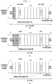
- Fig. 1 illustrates diagrams showing describe examples of a channel sensing signal design according to an embodiment of the present invention.
- the frame structure is an LTE uplink.
- one subframe 100 has 1 ms in length of time and is divided into two slots, slot 0 (indicated by reference number 101) and slot 1 (indicated by reference number 102).
- Each slot has seven Single Carrier - Frequency Division Multiple Access (SC-FDMA) symbols 103. It is assumed that the first SC-FDMA symbol and the last SC-FDMA symbol of a sub-frame are used as Guard Period (GP).
- GP is set for switching between transmission and reception in a terminal, considering the half-duplex in D2D communication.
- the SC-FDMA symbol in the center of each slot transmits a reference signal that a terminal uses for modulation over a frequency domain, i.e., Demodulation Reference Signal (DM RS).
- DM RS Demodulation Reference Signal
- Diagram (a) of Fig. 1 is a first example showing a sub-frame using a channel sensing signal of an RS structure or a preamble which, which differs from the DM RS.
- the channel sensing signal 104 may be transmitted via an SC-FDMA symbol next to the GP of slot 0.
- Diagram (b) of Fig. 1 is a second example showing a sub-frame that uses a channel sensing signal of an RS structure or a preamble which, which differs from the DM RS and, and that transmits a channel sensing signal 105 over the two SC-FDMA symbols between the TP of slot 0 and the DM RS.
- the channel sensing signal 105 may be designed: to have preambles or RS sequences according to SC-FDMA symbols, individual, respectively; or to have a length of one preamble or RS sequence so that it can be transmitted via two SC-FDMA symbols.
- SC-FDMA symbols of a channel sensing signal may not be limited to the examples described above.
- SC-FDMA symbols of a channel sensing signal may be transmitted via any slot 0 or slot 1.
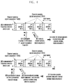
- Channel sensing signal sequence 1 (indicated by reference number 200) is defined as the last transmission sub-frame of the sub-frames transmitted by a current transmitting terminal.
- Channel sensing signal sequence 2 (indicated by reference number 201) is defined as one of the sub-frame transmitted by a current transmitting terminal, indicating that it will continue transmitting data.
- D2D terminals transmit data via the overall frequency domain set for D2D communication resources.
- the top of the diagram shows a first example of a D2D communication method when terminals A, B, and C (corresponding to UE A, UE B, UE C, respectively in Fig. 2 ) use data services via D2D communication. It is assumed that terminal A uses a D2D communication resource and terminals A, B, and C have data to be transmitted.
- terminal A When using a data service generally, terminal A transmits its data via successive sub-frames. When transmitting the last sub-frame of the successive sub-frames, terminal A transmits channel sensing signal sequence 1 along therewith, thereby informing other terminals that it does not use the other sub-frames after the last sub-frame. After that, terminal A transmits channel sensing signal sequence 2 via other sub-frames except for the last sub-frame, thereby informing other terminals that it will use sub-frames after the sequence 2. This makes other terminals (i.e., terminal B and terminal C) performing a channel sensing process recognize a time when the currently used D2D communication resources are empty.
- terminal C since terminal C has a smaller length of back-off section than terminal B at a time point that transmission of terminal A is ended, it transmits data earlier than terminal B.
- terminal B When the length of back-off section is randomly set at another back-off start time point that terminal C ends the transmission, terminal B has a smaller length of back-off section than terminal A, thereby performing transmission of data.
- terminals can recognize a time when data transmission is ended, without employing an additional channel for the transmission of control information regarding a data transmission length.
- a setting of resources to be used by individual terminals is determined in semi-persistent scheduling mode. For example, when terminal A transmits voice data via one sub-frame, it uses sub-frames after its cycle length. Therefore, when using voice services, since a terminal uses sub-frames not successively but with a specific cycle, other terminals may use sub-frames between the specific cycles.
- terminal A transmits its voice data along with channel sensing signal sequence 1 via one sub-frame.
- Terminal A uses channel sensing signal sequence 1 and this is because the voice data transmitted by terminal A does not use successive sub-frames as the first example of Fig. 2 . That is, after using one frame, the voice data transmitted by terminal A does not use sub-frames until the next cycle.
- terminal B and terminal C detect the channel sensing signal sequence 1 and ascertain that the next sub-frame has not been used, they perform a random back-off process and a voice data transmission, as the first example of Fig. 2 .
- terminal C since terminal C has a smaller length of back-off section than terminal B at a time point that transmission of terminal A is ended, it transmit data earlier than terminal B.
- terminal A Ascertains that the next transmission cycle of voice data arrives, it may transmit its voice data along with channel sensing signal sequence 1 via one sub-frame.
- terminal B When the length of back-off section is randomly set at a time point that the transmission of terminal A is ended, terminal B has a smaller length of back-off section than terminal C, thereby performing transmission of voice data.
- Another method according to the embodiment may be implemented in such a way as to: predefine a number of resource settings for supporting voice services and inform other terminals a resource setting in use via a channel sensing signal sequence.
- other terminals since other terminals can estimate a resource that the current transmitting terminal will use later, they transmit their signals via other resources excluding the resource estimated to be in use, thereby reducing a conflict of transmitting terminal resources.
- Channel sensing signal sequence 1 (indicated by reference number 300) is defined to indicate that a sub-frame transmitted by a current transmitting terminal provides a voice service.
- Channel sensing signal sequence 2 (indicated by reference number 301) is defined to indicate that a sub-frame transmitted by a current transmitting terminal provides a data service.
- Channel sensing signal sequence 3 (indicated by reference number 303) is defined to indicate that a sub-frame transmitted by a current transmitting terminal is the last transmission sub-frame.
- D2D terminals transmit data via the overall frequency domain set for D2D communication resources.
- the top of the diagram shows a first example of a D2D communication method when terminals A, B, and C (corresponding to UE A, UE B, UE C, respectively in Fig. 3 ) use data services via D2D communication. It is assumed that terminal A uses a D2D communication resource and terminals A, B, and C have data to be transmitted.
- the first example of Fig. 3 is similar to that of Fig. 2 in terms of the operations of terminals A, B, and C. However, there is a difference between the first example of Fig. 3 and that of Fig. 2 as follows: when the sub-frame transmitted by a terminal is not the last sub-frame, a channel sensing signal sequence transmitted along with the sub-frame indicates a state using successive sub-frames and a service type of data transmitted via the current sub-frame.
- terminal A transmits its data via successive sub-frames.
- terminal A transmits channel sensing signal sequence 3 (302) along therewith, thereby informing other terminals that it does not use the other sub-frames after the last sub-frame.
- terminal A transmits channel sensing signal sequence 2 (302) via other sub-frames except for the last sub-frame, thereby informing other terminals (i.e., terminal B and terminal C) that the sub-frames transmitted by terminal A after the sequence 2 are for a data service.
- FIG. 3 the bottom of the diagram shows a second example of a D2D communication method when terminals A, B, and C (corresponding to UE A, UE B, UE C, respectively in Fig. 3 ) use voice services via D2D communication. It is assumed that terminal A uses a D2D communication resource and terminals A, B, and C have data to be transmitted.
- the second example of Fig. 3 is similar to that of Fig. 2 in terms of the operations of terminals A, B, C. However, there is a difference between the second example of Fig. 3 and that of Fig.
- the present disclosure described an example a data service and another example using a voice service separately, it should be understood that the present invention may also be applied to an environment simultaneously using a data service and a voice service.
- the maximum number of successively transmittable sub-frames for data service may be set to be less than the sub-frame cycle set for voice service.
- Channel sensing signal sequence 1 (indicated by reference number 400) is defined to indicate that a packet transmitted by a current transmitting terminal is the initial transmission.
- Channel sensing signal sequence 2 (indicated by reference number 401) is defined to indicate that a packet transmitted by a current transmitting terminal is not the initial transmission.
- D2D terminals transmit data via the overall frequency domain set for D2D communication resources.
- the top of the diagram shows a first example of an operation of terminal B (corresponding to UE B in Fig. 4 ) when terminal B participates in a new D2D communication group or terminal B does not detect a packet that current transmitting terminal A (corresponding to UE A in Fig. 4 ) has transmitted.
- the terminal B may receive the second packet and thereafter that terminal A is transmitting.
- the terminal B is capable of receiving a channel sensing signal sequence 2 (indicated by reference number 401), along with the second packet transmitted by terminal A.
- the terminal B is capable of recognizing that the currently received packet is not a packet by the initial transmission, by detecting channel sensing signal sequence 2 (401). Since channel sensing signal sequence 2 (401) means a presence of a packet which has been lost before a packet that terminal B receives, terminal B does not decode packets where channel sensing signal sequence 2 (401) is detected.
- the bottom of the diagram shows a second example of an operation of terminal B (corresponding to UE B in Fig. 4 ) when terminal B does not completely detect packets that current transmitting terminal A (corresponding to UE A in Fig. 4 ) is transmitting.
- the terminal B may receive the first packet and thereafter that terminal A is transmitting.
- the terminal B is capable of receiving a channel sensing signal sequence 1 (indicated by reference number 400), along with the first packet transmitted by terminal A.
- the terminal B is capable of recognizing that the currently received packet is a packet by the initial transmission, by detecting channel sensing signal sequence 1 (400). Since channel sensing signal sequence 1 (400) means there has been no lost packet, terminal B decodes packets where channel sensing signal sequence 2 (401) is detected.
- the embodiment enables a receiving terminal to recognize a condition as to whether a packet has been lost, without employing an additional channel for transmitting control information, thereby preventing the terminal from performing an unnecessary decoding process.
- Fig. 5 illustrates diagrams that describe another example of a method of performing D2D communication when a channel sensing signal contains transmission packet identification information according to an embodiment the present invention.
- terminal A when terminal A (corresponding UE A in Fig. 5 ) transmits its data, it may transmit IR versions that differ from each other, via each of the four successive sub-frames, instead of a sub-frame.
- a receiving terminal identifies an IR version of a currently received sub-frame, by detecting a channel sensing signal sequence, and decodes a corresponding packet, based on the IR version.
- the embodiment can provide useful control information to a decoding process of a receiving terminal, without employing an addition control channel.
- Fig. 6 illustrates a diagram that describes a method of performing D2D communication when a channel sensing signal contains transmission packet identification information and MCS information according to an embodiment of the present invention.
- Channel sensing signal sequence 1 (indicated by reference number 600) is defined to indicate that a packet transmitted by a current transmitting terminal is the initial transmission.
- Channel sensing signal sequence 2 (indicated by reference number 601) is defined to indicate that a packet transmitted by a current transmitting terminal is not the initial transmission.
- Channel sensing signal sequence 1' (indicated by reference number 602) is defined as MCS level 0.
- Channel sensing signal sequence 2' (indicated by reference number 603) is defined as MCS level 1.
- D2D terminals transmit data via the overall frequency domain set for D2D communication resources, and available MCS levels are level 0 and level 1.
- the initial transmission sub-frame uses MCS level of 0 and successive sub-frames use MCS level of 1; however, it should be understood that MCS levels of 0 and 1 may be applied to any sub-frames with limitation.
- terminal B may realizes a presence of a packet that has been lost before its received packet. Therefore, terminal B may not decode packets where channel sensing signal sequence 2 (601) is detected.
- the embodiment can inform a receiving terminal of a number of types of control information, using channel sensing signal sequences, without employing a number of control channels.
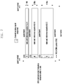
- a number of terminals share D2D communication frequency resources set in sub-frames in Frequency Division Multiplex (FDM). It is also assumed that the number of successive RBs that terminals can use is set to 1, 2, or 4, and individual terminals transmit data via a frequency resource of a size corresponding to one of the three settings.
- FDM Frequency Division Multiplex
- the first section of N SC-FDMA symbols 700 in a sub-frame may be used as a channel sensing signal region.
- the size of a frequency resource occupied by a channel sensing signal is identical to that of the frequency resource that a transmitting terminal uses for data transmission. That is, when a terminal sets a frequency resource to a size corresponding to one of the number of RBs, 1, 2, and 4, to transmit data, the channel sensing signal is also designed in such a way that the sequence has a length occupying 1, 2, or 4 RBs on the frequency domain. Therefore, according to the embodiment, a channel sensing signal indicates a frequency resource for data transmission via the length of a specific sequence.
- the receiving terminal may recognize that data of terminal B is transmitted to a region of 2 RBs, based on the detected RB location.
- a receiving terminal takes a correlation on a channel sensing signal region with a channel sensing sequence (703) of 4 RBs, and thus detects a channel sensing signal of terminal C and the corresponding data transmission frequency resource.
- the embodiment can indicate frequency resource allocating information obtained from a channel sensing signal, without employing an additional control channel.
- Fig. 8 illustrates a diagram showing another example of a frame structure when a channel sensing signal contains information regarding transmission frequency resources according to an embodiment of the present invention.
- the first section of N SC-FDMA symbols 800 in a sub-frame may be used as a channel sensing signal region.
- the sizes of frequency resource occupied by channel sensing signals are identical to each other.
- the embodiment is described, based on three channel sensing signal sequences 1, 2, and 3.
- Channel sensing signal sequence 1 (801) is defined to indicate that the size of transmission data by a corresponding terminal is 1 RB
- channel sensing signal sequence 2 (802) is defined to indicate that the size of transmission data by a corresponding terminal is 2 RBs
- channel sensing signal sequence 3 (803) is defined to indicate that the size of transmission data by a corresponding terminal is 4 RBs.
- a receiving terminal attempts to perform blind detection on the channel sensing signal region.
- a receiving terminal takes a correlation on a channel sensing signal region with a channel sensing sequence 1 (801), and thus detects a channel sensing signal of terminal A.
- the receiving terminal may recognize that data of terminal A is transmitted to a region of 1 RB, based on the detected RB location.
- a receiving terminal takes a correlation on a channel sensing signal region with a channel sensing sequence 2 (802), and thus detects a channel sensing signal of terminal B.
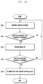
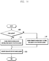
- Fig. 9 is a flowchart that describes a method of performing operations in a transmitting terminal when a channel sensing signal contains information as to whether it is the last transmission according to an embodiment of the present invention.
- Fig. 10 is a flowchart that describes a method of performing operations in a receiving terminal that needs to perform the data transmission when a channel sensing signal contains information as to whether it is the last transmission according to an embodiment of the present invention.
- a receiving terminal that needs data transmission performs a channel sensing process to attempt to detect a channel sensing signal in operation 1000.
- the receiving terminal detects a channel sensing signal transmitted from a current transmitting terminal and determines whether the next resource, i.e., the next sub-frame, is available, based on the detected channel sensing signal in operation 1001.
- the receiving terminal determines that the next resource is available in operation 1001, it performs a random back-off process from the end of the current sub-frame to perform a channel sensing process during the randomly set back-off time in operation 1002.
- the receiving terminal when the receiving terminal ascertains that a corresponding resource is available, based on the result of the channel sensing process, in operation 1003, it is capable of transmitting its channel sensing signal along with data in operation 1004.
- the receiving terminal when the receiving terminal ascertains that the next resource is not available, based on the detection of the channel sensing signal in operation 1001, it returns to and performs a channel sensing process in operation 1000.
- the receiving terminal when the receiving terminal ascertains that a corresponding resource is not available, based on the result of the random back-off process, in operation 1003, it returns to and performs a channel sensing process in operation 1000.
- Fig. 11 is a flowchart that describes a method of performing operations in a transmitting terminal when a channel sensing signal contains transmission packet identification information according to an embodiment of the present invention.
- Fig. 12 is a flowchart that describes a method of performing operations in a receiving terminal when a channel sensing signal contains transmission packet identification information according to an embodiment of the present invention.
- the receiving terminal when the receiving terminal ascertains that the received packet is not a packet by the initial transmission in operation 1201, which means that there is a packet that has been lost, it returns to operation 1200, without decoding the currently received packet and packets successively received thereafter.
- Fig. 13 shows block diagrams of a D2D transmitting terminal and a D2D receiving terminal according to an embodiment of the present invention. More specifically, diagram (a) of Fig. 13 is a block diagram showing a transmitting terminal and diagram (b) of Fig. 13 is a block diagram showing a receiving terminal.
- the transmitting terminal may further include a channel sensing signal creating unit 1301.
- the channel sensing signal creating unit 1301 is capable of creating channel sensing signal sequences based on control information from the controller 1300.
- the communication unit 1302 performs transmission/reception of signals according to operations of the embodiments described above. For example, the communication unit 1302 carries the created channel sensing signal sequence on a channel sensing signal transmission resource, multiplexes it with a data channel crated based on the control information, and transmits them together.
- the communication unit 1302 may be configured to include a D2D transmitting unit.
- the D2D transmitting unit carries the created channel sensing signal sequence on a channel sensing signal transmission resource, multiplexes it with a data channel created based on the control information, and transmits them together.
- the receiving terminal is capable of including a controller 1305 and communication units 1303 and 1307.
- the communication units 1303 and 1307 may be configured to be a D2D receiving unit and a D2D transmitting unit, respectively.
- the controller 1305 controls the receiving terminal to perform operations for the embodiments described above.
- the controller 1305 controls the D2D receiving unit 1303 to: receive D2D signals from the transmitting terminal; separate channel sensing signals from the D2D signals; detect channel sensing signals; and precisely decode the received data based on the channel sensing signals.
- the controller 1305 creates a channel sensing signal sequence, and the D2D transmitting unit carries the created channel sensing signal sequence on a channel sensing signal transmission resource, multiplexes it with a data channel crated based on the control information, and transmits them together.
- the communication units 1303 and 1307 perform reception/transmission of signals according to operations of the embodiments described above.
- the communication unit is capable of receiving D2D signals from the transmitting terminal.
- the communication unit is also capable of carrying the created channel sensing signal sequence on a channel sensing signal transmission resource, multiplexing it with a data channel crated based on the control information, and transmitting them together.
- the receiving terminal may further include a channel sensing signal detecting unit 1304 and a channel sensing signal creating unit 1306.
- the D2D receiving unit 1303 receives D2D signals from the transmitting terminal and separates a channel sensing signal therefrom.
- the channel sensing signal detecting unit 1304 detects the channel sensing signal to obtain control information and transfers the obtained control information to the controller 1305.
- the controller 1305 controls the D2D receiving unit 1303 to precisely decode the received data based on the control information.
- the controller 1305 determines whether it transmits data, based on the control information obtained from the channel sensing signal detecting unit 1304, and controls the channel sensing signal creating unit 1306 and the D2D transmitting unit 1307 to transmit the data and the channel sensing signal. After that, the channel sensing signal creating unit 1306 creates a channel sensing signal sequence based on the control information, and the D2D transmitting unit 1307 carries the created channel sensing signal sequence on a channel sensing signal transmission resource, multiplexes it with a data channel created based on the control information, and transmits them together.
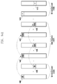
- Figs. 14a to 14c show diagrams that describe a method of performing D2D communication when a scheduling assignment (SA) signal contains resource occupation information according to an embodiment of the present invention.
- the data 1401 and 1402 is transmitted with two times of repletion as shown in Fig. 14a .
- the data 1404 and 1405 transmitted by terminal B is transmitted, via the same frequency resource as the SA 1403 related to the data, with two times of repletion, according to a pre-defined rule. It should be understood that the cycle and the number of data repetition transmission are not limited to the embodiment but may be set to any values, respectively.
- the terminal A and terminal B occupies specific resources in an SA transmittable/receivable resource region 1406 before a terminal (e.g., terminal C) transmits SA and data and a data resource region 1407 before terminal C transmits SA and data.
- terminal C planning to a new SA may perform an energy sensing process before the SA transmittable/receivable resource region 1408.
- terminal C may perform an energy sensing process for the data resource region 1407 that terminal A and terminal B occupy in order to transmit data.
- the terminal C ascertains that there is a terminal occupying resource 1409 and resource 1410, based on the result of the energy sensing process. In this case, the terminal C may not apply the two resources, i.e., resource 1409 and resource 1410, to the SA transmission. However, the terminal C planning to transmit SA does not determine whether the terminal A or terminal B will continue to occupy the SA resource region and data resource region, by performing only the energy sensing process for the data resource region 1408 occupied by the terminal A or terminal B. Therefore, when the terminal A or terminal B ends the resource occupation, terminal C planning to transmit SA may miss available resources, which is disadvantageous.
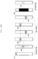
- Fig. 14b is a diagram when an SA signal of individual transmitting terminals explicitly notifies the related data resource.
- a terminal e.g., terminal C
- the data uses a frequency resource according to resource allocation information notified by the related SA and is transmitted with two times of repetition.
- the data 1412 and 1413 transmitted by terminal A is transmitted with two times of repetition, using a frequency resource according to resource allocation information notified by the related SA 1411.
- the data 1415 and 1416 transmitted by terminal B is transmitted with two times of repetition, using a frequency resource according to resource allocation information notified by the related SA 1414. It should be understood that the cycle and the number of data repetition transmission are not limited to the embodiment but may be set to any values, respectively.
- a terminal (e.g., terminal C) planning to transmit a new SA is capable of performing an energy sensing process in a resource region before a transmittable/receivable resource region 1408 to which terminal C plans to a corresponding SA.
- useful information for selecting an SA transmission resource by terminal C may not be obtained from a data resource region 1407 that terminal A and terminal B occupy and transmit data to before terminal C transmits SA and data. This is because the data resource is not related to a resource of the related SA. Therefore, terminal C planning to a new SA needs to perform a channel sensing process for an SA transmittable/receivable resource region 1406 before a transmittable/receivable resource region 1408 to which terminal C plans to a corresponding SA.
- the terminal C ascertains that there is a terminal occupying resource 1417 and resource 1418, based on the result of the channel sensing process. In this case, the terminal C may not apply the two resources, i.e., resource 1417 and resource 1418, to the SA transmission. However, the terminal C planning to transmit SA does not determine whether the terminal A or terminal B will continue to occupy the SA resource region and data resource region, by performing only the energy sensing process for the data resource region 1408 occupied by the terminal A or terminal B. Therefore, when the terminal A or terminal B ends the resource occupation, terminal C planning to transmit SA may miss available resources, which is disadvantageous.
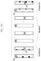
- Fig. 14c shows a diagram that describes a method of performing D2D communication when a scheduling assignment (SA) signal contains resource occupation information according to an embodiment of the present invention.
- the data resource may be determined according to resource allocation information explicitly notified by the related SA or may be implicitly determined according to resources of the related SA. Since it detailed description was already explained above, it is omitted below. It should be understood that the cycle and the number of data repetition transmission are not limited to the embodiment but may be set to any values, respectively.
- the SA 1420 of terminal A may contain information (e.g., 1 bit of information) indicating a condition as to whether it continues to occupy a resource in the next SA transmittable/receivable resource region 1408.
- terminal C plans to transmit a new SA in an SA transmittable/receivable resource region 1408 next to the resource regions 1406 and 1407 that terminal A and terminal B has occupied and transmitted SA and data to, it may perform an energy sensing process or an SA monitoring process before the SA transmittable/receivable resource region 1408.
- terminal C When terminal C ascertains that the next SA transmittable/receivable resource region exists in the currently received SA and SAs thereafter, based on the result of the energy sensing process or the SA monitoring process, it may discover a condition as to whether resources occupied by the received SAs will continue to be used. That is, when information regarding a condition as to whether terminal A continues to occupy resources, contained in SA 1420 transmitted by terminal A, indicates that terminal A will continue to occupy resources, a receiving terminal (i.e., terminal C) may discover that resource 1421 cannot be used in the next SA transmittable/receivable resource region 1408.
- the SA may contain information regarding the number of cycles of an SA transmittable/receivable resource region that resources will continue to occupy, instead of a condition as to whether to occupy the next SA transmittable/receivable resource.
- the SA 1422 of terminal B may contain information indicating a condition as to whether it continues to occupy a resource in the next SA transmittable/receivable resource region 1408.
- information indicating a condition as to whether terminal B continues to occupy resources, contained in the SA 1422 indicates that terminal B does not occupy resources
- a receiving terminal i.e., terminal C may discover that resource 1423 can be used in the next transmittable/receivable resource region 1408.
- the embodiment is implemented in such a way that one bit of information indicates a condition as to whether a terminal will continue to occupy an SA resource, it should be understood that the present invention is not limited to the embodiment. It may also be modified in such a way as to indicate a condition as to whether a terminal will continue to occupy resources in a number of SA transmittable/receivable resource regions, using two or more bits.
Landscapes
- Engineering & Computer Science (AREA)
- Computer Networks & Wireless Communication (AREA)
- Signal Processing (AREA)
- Mobile Radio Communication Systems (AREA)
Applications Claiming Priority (3)
| Application Number | Priority Date | Filing Date | Title |
|---|---|---|---|
| KR20130135731 | 2013-11-08 | ||
| KR1020140048635A KR102193118B1 (ko) | 2013-11-08 | 2014-04-23 | 기기 대 기기 통신을 위한 제어 정보 전송 방법 및 장치 |
| PCT/KR2014/010760 WO2015069080A1 (ko) | 2013-11-08 | 2014-11-10 | 기기 대 기기 통신을 위한 제어 정보 전송 방법 및 장치 |
Publications (3)
| Publication Number | Publication Date |
|---|---|
| EP3068061A1 true EP3068061A1 (de) | 2016-09-14 |
| EP3068061A4 EP3068061A4 (de) | 2017-12-20 |
| EP3068061B1 EP3068061B1 (de) | 2020-03-25 |
Family
ID=53390199
Family Applications (1)
| Application Number | Title | Priority Date | Filing Date |
|---|---|---|---|
| EP14859528.3A Active EP3068061B1 (de) | 2013-11-08 | 2014-11-10 | Verfahren und vorrichtung zur übertragung von steuerinformationen für d2d-kommunikationen |
Country Status (4)
| Country | Link |
|---|---|
| US (1) | US10334625B2 (de) |
| EP (1) | EP3068061B1 (de) |
| KR (1) | KR102193118B1 (de) |
| ES (1) | ES2784622T3 (de) |
Cited By (2)
| Publication number | Priority date | Publication date | Assignee | Title |
|---|---|---|---|---|
| WO2017184362A1 (en) * | 2016-04-20 | 2017-10-26 | Qualcomm Incorporated | Resource access priority for synchronous transmissions |
| EP3735061A1 (de) * | 2013-08-07 | 2020-11-04 | Interdigital Patent Holdings, Inc. | Verteilte planung für maschine-zu-maschine-kommunikationen |
Families Citing this family (12)
| Publication number | Priority date | Publication date | Assignee | Title |
|---|---|---|---|---|
| US10491354B2 (en) * | 2015-06-23 | 2019-11-26 | Electronics And Telecommunications Research Institute | Method and apparatus for transmitting data in direct device-to-device communication |
| KR102607062B1 (ko) * | 2015-06-23 | 2023-11-30 | 한국전자통신연구원 | 단말간 직접 통신에서의 데이터 전송 방법 및 장치 |
| KR102011823B1 (ko) * | 2015-07-03 | 2019-08-19 | 엘지전자 주식회사 | 단말 간 신호를 전송하는 방법 및 이를 위한 장치 |
| AU2015414016B2 (en) * | 2015-11-05 | 2020-11-12 | Panasonic Intellectual Property Corporation Of America | Wireless device and wireless communication method |
| JP6803458B2 (ja) * | 2016-08-11 | 2020-12-23 | 華為技術有限公司Huawei Technologies Co.,Ltd. | リソースエネルギを決定する方法および装置 |
| CN108966355B (zh) * | 2017-05-24 | 2021-06-08 | 华为技术有限公司 | 信道侦听方法、网络侧设备及终端 |
| WO2019058436A1 (ja) * | 2017-09-19 | 2019-03-28 | 株式会社Nttドコモ | ユーザ装置 |
| FR3081279A1 (fr) * | 2018-05-18 | 2019-11-22 | Orange | Procede centralise d'allocation de ressources de transmission a des terminaux d2d dans un reseau d'acces cellulaire. |
| US20230139912A1 (en) * | 2020-05-29 | 2023-05-04 | Qualcomm Incorporated | Channel busy measurements in sidelink communications |
| CN116033566A (zh) * | 2021-10-21 | 2023-04-28 | 中兴通讯股份有限公司 | 资源指示方法、节点和存储介质 |
| EP4380090A1 (de) * | 2022-12-02 | 2024-06-05 | Nxp B.V. | Vorrichtung zur kommunikation und erfassung |
| CN120050143B (zh) * | 2025-04-24 | 2025-07-18 | 杰创智能科技股份有限公司 | 5g共享信道参数估计方法、装置、电子设备和存储介质 |
Family Cites Families (17)
| Publication number | Priority date | Publication date | Assignee | Title |
|---|---|---|---|---|
| US8411619B2 (en) | 2007-09-21 | 2013-04-02 | Lg Electronics Inc. | Method of packet reordering and packet retransmission |
| WO2010000309A1 (en) * | 2008-07-01 | 2010-01-07 | Telefonaktiebolaget L M Ericsson (Publ) | Method and arrangement in a telecommunication system |
| US8908583B2 (en) | 2010-04-22 | 2014-12-09 | Lg Electronics Inc. | Method and device for allocating resources in wireless communication system |
| EP2617258B1 (de) | 2010-09-14 | 2019-03-27 | Nokia Technologies Oy | D2d-kommunikationsverfahren: beaconing, übertragung, konfliktauflösung |
| US8958307B2 (en) | 2010-12-25 | 2015-02-17 | Intel Corporation | Enabling coexistence of high-density and low-density transmissions |
| WO2012096493A2 (ko) | 2011-01-10 | 2012-07-19 | 엘지전자 주식회사 | 단말 간 통신을 지원하는 무선통신 시스템에서 단말 간 상향링크 신호 전송을 위한 전송 전력을 결정하는 방법 및 이를 위한 장치 |
| JP2013034165A (ja) | 2011-06-27 | 2013-02-14 | Ntt Docomo Inc | 無線通信方法、無線通信システム及び移動局 |
| EP2727424B1 (de) | 2011-06-29 | 2017-01-25 | Telefonaktiebolaget LM Ericsson (publ) | Methode und benutzergerät zur peer-to-peer kommunikation |
| WO2013077684A1 (ko) | 2011-11-24 | 2013-05-30 | 엘지전자 주식회사 | 무선 접속 시스템에서 단말 간 통신 수행 방법 및 이를 위한 장치 |
| WO2013115567A1 (ko) | 2012-01-30 | 2013-08-08 | 엘지전자 주식회사 | D2d 통신을 지원하는 무선통신 시스템에서 d2d 전송 데이터에 대한 피드백 정보를 전송 및 수신하는 방법과 이를 위한 장치 |
| KR102004833B1 (ko) * | 2012-03-23 | 2019-07-29 | 엘지전자 주식회사 | 무선랜 시스템에서 채널 액세스 방법 및 장치 |
| US8883021B2 (en) * | 2012-03-30 | 2014-11-11 | Taiwan Semiconductor Manufacturing Company, Ltd. | MEMS nanostructures and methods of forming the same |
| WO2013162333A1 (ko) | 2012-04-26 | 2013-10-31 | 한국전자통신연구원 | 부분적 단말 제어 단말 대 단말 통신 방법 |
| JP6829072B2 (ja) * | 2013-08-07 | 2021-02-10 | インターデイジタル パテント ホールディングス インコーポレイテッド | デバイスツーデバイス通信のための分散スケジューリング |
| CN105794294B (zh) * | 2013-10-31 | 2019-07-12 | 诺基亚技术有限公司 | 广播信道管理 |
| US20150245334A1 (en) * | 2014-02-27 | 2015-08-27 | Innovative Sonic Corporation | Method and apparatus for device to device service in a wireless communication system |
| US10524282B2 (en) * | 2014-03-19 | 2019-12-31 | Qualcomm Incorporated | Scheduling assignment content and transmission in wireless communications |
-
2014
- 2014-04-23 KR KR1020140048635A patent/KR102193118B1/ko not_active Expired - Fee Related
- 2014-11-10 EP EP14859528.3A patent/EP3068061B1/de active Active
- 2014-11-10 ES ES14859528T patent/ES2784622T3/es active Active
- 2014-11-10 US US15/033,362 patent/US10334625B2/en active Active
Cited By (3)
| Publication number | Priority date | Publication date | Assignee | Title |
|---|---|---|---|---|
| EP3735061A1 (de) * | 2013-08-07 | 2020-11-04 | Interdigital Patent Holdings, Inc. | Verteilte planung für maschine-zu-maschine-kommunikationen |
| WO2017184362A1 (en) * | 2016-04-20 | 2017-10-26 | Qualcomm Incorporated | Resource access priority for synchronous transmissions |
| US10231166B2 (en) | 2016-04-20 | 2019-03-12 | Qualcomm Incorporated | Resource access priority for synchronous transmissions |
Also Published As
| Publication number | Publication date |
|---|---|
| EP3068061B1 (de) | 2020-03-25 |
| US10334625B2 (en) | 2019-06-25 |
| ES2784622T3 (es) | 2020-09-29 |
| KR102193118B1 (ko) | 2020-12-18 |
| EP3068061A4 (de) | 2017-12-20 |
| KR20150053686A (ko) | 2015-05-18 |
| US20160278120A1 (en) | 2016-09-22 |
Similar Documents
| Publication | Publication Date | Title |
|---|---|---|
| EP3068061B1 (de) | Verfahren und vorrichtung zur übertragung von steuerinformationen für d2d-kommunikationen | |
| US20250211953A1 (en) | Method for selecting resource to be used for performing v2x communication within range satisfying latency requirement in wireless communication system, and terminal using same | |
| US11564072B2 (en) | Method for selecting, in selection period, subframe excluding subframe relating to subframe in which transmission has been performed during sensing period in wireless communication system, and terminal using same | |
| US12484040B2 (en) | Data transmission method, and apparatus | |
| EP3404991B1 (de) | Direktzugriffsverfahren, kommunikationknoten und nichttransitorisches computerlesbares medium | |
| EP4106431A1 (de) | Verfahren und vorrichtung zur bestimmung von zu erfassenden ressourcen für die kommunikation von gerät zu gerät in einem drahtlosen kommunikationssystem | |
| EP3820187B1 (de) | Verfahren zur gemeinsamen benutzung eines unlizenzierten kanals und speichermedium | |
| KR101689999B1 (ko) | 제어 채널 후보들의 개수 및 블라인드 검출 횟수를 할당하는 방법, 기지국, 및 사용자 장비 | |
| EP3316644B1 (de) | Sendevorrichtung, empfangsvorrichtung und verfahren für uplink-daten | |
| US20140348089A1 (en) | Data sending method, data receiving method, base station and user equipment | |
| US10321470B2 (en) | Method and apparatus for employing resource for device-to-device (D2D) wireless communication | |
| US10499392B2 (en) | Method and apparatus for resource allocation | |
| JP7171547B2 (ja) | 上りリンクデータ繰り返しモードを通知、確定する方法、ユーザ装置および基地局 | |
| KR20150128268A (ko) | 기기간 통신의 자원할당을 위한 분산 스케줄링 방법 및 장치 | |
| CN106453181A (zh) | 一种信息处理方法、装置及系统 | |
| EP3259952A1 (de) | Verfahren, computerprogramme, netzwerkknoten und kommunikationsvorrichtung | |
| KR102221959B1 (ko) | 단말 대 단말 통신에서 분산 자원 할당을 위한 기준 신호 송 수신 방법 및 장치 | |
| EP4598229A1 (de) | Planungsverfahren und vorrichtung zur kommunikation zwischen endgeräten eines kommunikationssystems |
Legal Events
| Date | Code | Title | Description |
|---|---|---|---|
| PUAI | Public reference made under article 153(3) epc to a published international application that has entered the european phase |
Free format text: ORIGINAL CODE: 0009012 |
|
| 17P | Request for examination filed |
Effective date: 20160506 |
|
| AK | Designated contracting states |
Kind code of ref document: A1 Designated state(s): AL AT BE BG CH CY CZ DE DK EE ES FI FR GB GR HR HU IE IS IT LI LT LU LV MC MK MT NL NO PL PT RO RS SE SI SK SM TR |
|
| AX | Request for extension of the european patent |
Extension state: BA ME |
|
| DAX | Request for extension of the european patent (deleted) | ||
| RIC1 | Information provided on ipc code assigned before grant |
Ipc: H04B 7/24 20060101AFI20170630BHEP Ipc: H04W 74/00 20090101ALI20170630BHEP |
|
| A4 | Supplementary search report drawn up and despatched |
Effective date: 20171116 |
|
| RIC1 | Information provided on ipc code assigned before grant |
Ipc: H04W 74/00 20090101ALI20171110BHEP Ipc: H04B 7/24 20060101AFI20171110BHEP |
|
| STAA | Information on the status of an ep patent application or granted ep patent |
Free format text: STATUS: EXAMINATION IS IN PROGRESS |
|
| 17Q | First examination report despatched |
Effective date: 20190424 |
|
| REG | Reference to a national code |
Ref country code: DE Ref legal event code: R079 Ref document number: 602014062956 Country of ref document: DE Free format text: PREVIOUS MAIN CLASS: H04B0007240000 Ipc: H04W0074080000 |
|
| GRAP | Despatch of communication of intention to grant a patent |
Free format text: ORIGINAL CODE: EPIDOSNIGR1 |
|
| STAA | Information on the status of an ep patent application or granted ep patent |
Free format text: STATUS: GRANT OF PATENT IS INTENDED |
|
| RIC1 | Information provided on ipc code assigned before grant |
Ipc: H04W 74/08 20090101AFI20191015BHEP Ipc: H04W 72/04 20090101ALI20191015BHEP |
|
| INTG | Intention to grant announced |
Effective date: 20191118 |
|
| GRAS | Grant fee paid |
Free format text: ORIGINAL CODE: EPIDOSNIGR3 |
|
| GRAA | (expected) grant |
Free format text: ORIGINAL CODE: 0009210 |
|
| STAA | Information on the status of an ep patent application or granted ep patent |
Free format text: STATUS: THE PATENT HAS BEEN GRANTED |
|
| AK | Designated contracting states |
Kind code of ref document: B1 Designated state(s): AL AT BE BG CH CY CZ DE DK EE ES FI FR GB GR HR HU IE IS IT LI LT LU LV MC MK MT NL NO PL PT RO RS SE SI SK SM TR |
|
| REG | Reference to a national code |
Ref country code: GB Ref legal event code: FG4D |
|
| REG | Reference to a national code |
Ref country code: AT Ref legal event code: REF Ref document number: 1250085 Country of ref document: AT Kind code of ref document: T Effective date: 20200415 Ref country code: IE Ref legal event code: FG4D |
|
| REG | Reference to a national code |
Ref country code: DE Ref legal event code: R096 Ref document number: 602014062956 Country of ref document: DE |
|
| REG | Reference to a national code |
Ref country code: FI Ref legal event code: FGE |
|
| PG25 | Lapsed in a contracting state [announced via postgrant information from national office to epo] |
Ref country code: RS Free format text: LAPSE BECAUSE OF FAILURE TO SUBMIT A TRANSLATION OF THE DESCRIPTION OR TO PAY THE FEE WITHIN THE PRESCRIBED TIME-LIMIT Effective date: 20200325 Ref country code: NO Free format text: LAPSE BECAUSE OF FAILURE TO SUBMIT A TRANSLATION OF THE DESCRIPTION OR TO PAY THE FEE WITHIN THE PRESCRIBED TIME-LIMIT Effective date: 20200625 |
|
| PG25 | Lapsed in a contracting state [announced via postgrant information from national office to epo] |
Ref country code: BG Free format text: LAPSE BECAUSE OF FAILURE TO SUBMIT A TRANSLATION OF THE DESCRIPTION OR TO PAY THE FEE WITHIN THE PRESCRIBED TIME-LIMIT Effective date: 20200625 Ref country code: GR Free format text: LAPSE BECAUSE OF FAILURE TO SUBMIT A TRANSLATION OF THE DESCRIPTION OR TO PAY THE FEE WITHIN THE PRESCRIBED TIME-LIMIT Effective date: 20200626 Ref country code: LV Free format text: LAPSE BECAUSE OF FAILURE TO SUBMIT A TRANSLATION OF THE DESCRIPTION OR TO PAY THE FEE WITHIN THE PRESCRIBED TIME-LIMIT Effective date: 20200325 Ref country code: HR Free format text: LAPSE BECAUSE OF FAILURE TO SUBMIT A TRANSLATION OF THE DESCRIPTION OR TO PAY THE FEE WITHIN THE PRESCRIBED TIME-LIMIT Effective date: 20200325 Ref country code: SE Free format text: LAPSE BECAUSE OF FAILURE TO SUBMIT A TRANSLATION OF THE DESCRIPTION OR TO PAY THE FEE WITHIN THE PRESCRIBED TIME-LIMIT Effective date: 20200325 |
|
| REG | Reference to a national code |
Ref country code: NL Ref legal event code: MP Effective date: 20200325 |
|
| REG | Reference to a national code |
Ref country code: LT Ref legal event code: MG4D |
|
| REG | Reference to a national code |
Ref country code: ES Ref legal event code: FG2A Ref document number: 2784622 Country of ref document: ES Kind code of ref document: T3 Effective date: 20200929 |
|
| PG25 | Lapsed in a contracting state [announced via postgrant information from national office to epo] |
Ref country code: NL Free format text: LAPSE BECAUSE OF FAILURE TO SUBMIT A TRANSLATION OF THE DESCRIPTION OR TO PAY THE FEE WITHIN THE PRESCRIBED TIME-LIMIT Effective date: 20200325 |
|
| PG25 | Lapsed in a contracting state [announced via postgrant information from national office to epo] |
Ref country code: PT Free format text: LAPSE BECAUSE OF FAILURE TO SUBMIT A TRANSLATION OF THE DESCRIPTION OR TO PAY THE FEE WITHIN THE PRESCRIBED TIME-LIMIT Effective date: 20200818 Ref country code: EE Free format text: LAPSE BECAUSE OF FAILURE TO SUBMIT A TRANSLATION OF THE DESCRIPTION OR TO PAY THE FEE WITHIN THE PRESCRIBED TIME-LIMIT Effective date: 20200325 Ref country code: SM Free format text: LAPSE BECAUSE OF FAILURE TO SUBMIT A TRANSLATION OF THE DESCRIPTION OR TO PAY THE FEE WITHIN THE PRESCRIBED TIME-LIMIT Effective date: 20200325 Ref country code: SK Free format text: LAPSE BECAUSE OF FAILURE TO SUBMIT A TRANSLATION OF THE DESCRIPTION OR TO PAY THE FEE WITHIN THE PRESCRIBED TIME-LIMIT Effective date: 20200325 Ref country code: RO Free format text: LAPSE BECAUSE OF FAILURE TO SUBMIT A TRANSLATION OF THE DESCRIPTION OR TO PAY THE FEE WITHIN THE PRESCRIBED TIME-LIMIT Effective date: 20200325 Ref country code: IS Free format text: LAPSE BECAUSE OF FAILURE TO SUBMIT A TRANSLATION OF THE DESCRIPTION OR TO PAY THE FEE WITHIN THE PRESCRIBED TIME-LIMIT Effective date: 20200725 Ref country code: CZ Free format text: LAPSE BECAUSE OF FAILURE TO SUBMIT A TRANSLATION OF THE DESCRIPTION OR TO PAY THE FEE WITHIN THE PRESCRIBED TIME-LIMIT Effective date: 20200325 Ref country code: LT Free format text: LAPSE BECAUSE OF FAILURE TO SUBMIT A TRANSLATION OF THE DESCRIPTION OR TO PAY THE FEE WITHIN THE PRESCRIBED TIME-LIMIT Effective date: 20200325 |
|
| REG | Reference to a national code |
Ref country code: AT Ref legal event code: MK05 Ref document number: 1250085 Country of ref document: AT Kind code of ref document: T Effective date: 20200325 |
|
| REG | Reference to a national code |
Ref country code: DE Ref legal event code: R097 Ref document number: 602014062956 Country of ref document: DE |
|
| PG25 | Lapsed in a contracting state [announced via postgrant information from national office to epo] |
Ref country code: AT Free format text: LAPSE BECAUSE OF FAILURE TO SUBMIT A TRANSLATION OF THE DESCRIPTION OR TO PAY THE FEE WITHIN THE PRESCRIBED TIME-LIMIT Effective date: 20200325 Ref country code: IT Free format text: LAPSE BECAUSE OF FAILURE TO SUBMIT A TRANSLATION OF THE DESCRIPTION OR TO PAY THE FEE WITHIN THE PRESCRIBED TIME-LIMIT Effective date: 20200325 Ref country code: DK Free format text: LAPSE BECAUSE OF FAILURE TO SUBMIT A TRANSLATION OF THE DESCRIPTION OR TO PAY THE FEE WITHIN THE PRESCRIBED TIME-LIMIT Effective date: 20200325 |
|
| PLBE | No opposition filed within time limit |
Free format text: ORIGINAL CODE: 0009261 |
|
| STAA | Information on the status of an ep patent application or granted ep patent |
Free format text: STATUS: NO OPPOSITION FILED WITHIN TIME LIMIT |
|
| PG25 | Lapsed in a contracting state [announced via postgrant information from national office to epo] |
Ref country code: PL Free format text: LAPSE BECAUSE OF FAILURE TO SUBMIT A TRANSLATION OF THE DESCRIPTION OR TO PAY THE FEE WITHIN THE PRESCRIBED TIME-LIMIT Effective date: 20200325 |
|
| 26N | No opposition filed |
Effective date: 20210112 |
|
| PG25 | Lapsed in a contracting state [announced via postgrant information from national office to epo] |
Ref country code: SI Free format text: LAPSE BECAUSE OF FAILURE TO SUBMIT A TRANSLATION OF THE DESCRIPTION OR TO PAY THE FEE WITHIN THE PRESCRIBED TIME-LIMIT Effective date: 20200325 |
|
| PG25 | Lapsed in a contracting state [announced via postgrant information from national office to epo] |
Ref country code: MC Free format text: LAPSE BECAUSE OF FAILURE TO SUBMIT A TRANSLATION OF THE DESCRIPTION OR TO PAY THE FEE WITHIN THE PRESCRIBED TIME-LIMIT Effective date: 20200325 |
|
| REG | Reference to a national code |
Ref country code: CH Ref legal event code: PL |
|
| GBPC | Gb: european patent ceased through non-payment of renewal fee |
Effective date: 20201110 |
|
| PG25 | Lapsed in a contracting state [announced via postgrant information from national office to epo] |
Ref country code: LU Free format text: LAPSE BECAUSE OF NON-PAYMENT OF DUE FEES Effective date: 20201110 |
|
| REG | Reference to a national code |
Ref country code: BE Ref legal event code: MM Effective date: 20201130 |
|
| PG25 | Lapsed in a contracting state [announced via postgrant information from national office to epo] |
Ref country code: CH Free format text: LAPSE BECAUSE OF NON-PAYMENT OF DUE FEES Effective date: 20201130 Ref country code: LI Free format text: LAPSE BECAUSE OF NON-PAYMENT OF DUE FEES Effective date: 20201130 |
|
| PG25 | Lapsed in a contracting state [announced via postgrant information from national office to epo] |
Ref country code: FR Free format text: LAPSE BECAUSE OF NON-PAYMENT OF DUE FEES Effective date: 20201130 Ref country code: IE Free format text: LAPSE BECAUSE OF NON-PAYMENT OF DUE FEES Effective date: 20201110 |
|
| PG25 | Lapsed in a contracting state [announced via postgrant information from national office to epo] |
Ref country code: GB Free format text: LAPSE BECAUSE OF NON-PAYMENT OF DUE FEES Effective date: 20201110 |
|
| PGFP | Annual fee paid to national office [announced via postgrant information from national office to epo] |
Ref country code: ES Payment date: 20211210 Year of fee payment: 8 Ref country code: FI Payment date: 20211020 Year of fee payment: 8 |
|
| PG25 | Lapsed in a contracting state [announced via postgrant information from national office to epo] |
Ref country code: TR Free format text: LAPSE BECAUSE OF FAILURE TO SUBMIT A TRANSLATION OF THE DESCRIPTION OR TO PAY THE FEE WITHIN THE PRESCRIBED TIME-LIMIT Effective date: 20200325 Ref country code: MT Free format text: LAPSE BECAUSE OF FAILURE TO SUBMIT A TRANSLATION OF THE DESCRIPTION OR TO PAY THE FEE WITHIN THE PRESCRIBED TIME-LIMIT Effective date: 20200325 Ref country code: CY Free format text: LAPSE BECAUSE OF FAILURE TO SUBMIT A TRANSLATION OF THE DESCRIPTION OR TO PAY THE FEE WITHIN THE PRESCRIBED TIME-LIMIT Effective date: 20200325 |
|
| PG25 | Lapsed in a contracting state [announced via postgrant information from national office to epo] |
Ref country code: MK Free format text: LAPSE BECAUSE OF FAILURE TO SUBMIT A TRANSLATION OF THE DESCRIPTION OR TO PAY THE FEE WITHIN THE PRESCRIBED TIME-LIMIT Effective date: 20200325 Ref country code: AL Free format text: LAPSE BECAUSE OF FAILURE TO SUBMIT A TRANSLATION OF THE DESCRIPTION OR TO PAY THE FEE WITHIN THE PRESCRIBED TIME-LIMIT Effective date: 20200325 |
|
| PG25 | Lapsed in a contracting state [announced via postgrant information from national office to epo] |
Ref country code: BE Free format text: LAPSE BECAUSE OF NON-PAYMENT OF DUE FEES Effective date: 20201130 |
|
| REG | Reference to a national code |
Ref country code: ES Ref legal event code: FD2A Effective date: 20231229 |
|
| PG25 | Lapsed in a contracting state [announced via postgrant information from national office to epo] |
Ref country code: ES Free format text: LAPSE BECAUSE OF NON-PAYMENT OF DUE FEES Effective date: 20221111 |
|
| PG25 | Lapsed in a contracting state [announced via postgrant information from national office to epo] |
Ref country code: ES Free format text: LAPSE BECAUSE OF NON-PAYMENT OF DUE FEES Effective date: 20221111 |
|
| PGFP | Annual fee paid to national office [announced via postgrant information from national office to epo] |
Ref country code: DE Payment date: 20231023 Year of fee payment: 10 |
|
| PG25 | Lapsed in a contracting state [announced via postgrant information from national office to epo] |
Ref country code: FI Free format text: LAPSE BECAUSE OF NON-PAYMENT OF DUE FEES Effective date: 20221110 |
|
| REG | Reference to a national code |
Ref country code: DE Ref legal event code: R119 Ref document number: 602014062956 Country of ref document: DE |
|
| PG25 | Lapsed in a contracting state [announced via postgrant information from national office to epo] |
Ref country code: DE Free format text: LAPSE BECAUSE OF NON-PAYMENT OF DUE FEES Effective date: 20250603 |
|
| PG25 | Lapsed in a contracting state [announced via postgrant information from national office to epo] |
Ref country code: IS Free format text: LAPSE BECAUSE OF NON-PAYMENT OF DUE FEES Effective date: 20200725 |