EP3068202B1 - Ansteuerungsvorrichtung, wärmeableitende vorrichtung und verfahren für eine schwingende lautsprecher-membranspule sowie mobiles endgerät - Google Patents
Ansteuerungsvorrichtung, wärmeableitende vorrichtung und verfahren für eine schwingende lautsprecher-membranspule sowie mobiles endgerät Download PDFInfo
- Publication number
- EP3068202B1 EP3068202B1 EP14872793.6A EP14872793A EP3068202B1 EP 3068202 B1 EP3068202 B1 EP 3068202B1 EP 14872793 A EP14872793 A EP 14872793A EP 3068202 B1 EP3068202 B1 EP 3068202B1
- Authority
- EP
- European Patent Office
- Prior art keywords
- speaker
- vibrating diaphragm
- heat dissipating
- coil
- frequency
- Prior art date
- Legal status (The legal status is an assumption and is not a legal conclusion. Google has not performed a legal analysis and makes no representation as to the accuracy of the status listed.)
- Not-in-force
Links
Images



Classifications
-
- H—ELECTRICITY
- H04—ELECTRIC COMMUNICATION TECHNIQUE
- H04R—LOUDSPEAKERS, MICROPHONES, GRAMOPHONE PICK-UPS OR LIKE ACOUSTIC ELECTROMECHANICAL TRANSDUCERS; ELECTRIC HEARING AIDS; PUBLIC ADDRESS SYSTEMS
- H04R9/00—Transducers of moving-coil, moving-strip, or moving-wire type
- H04R9/02—Details
- H04R9/022—Cooling arrangements
-
- H—ELECTRICITY
- H04—ELECTRIC COMMUNICATION TECHNIQUE
- H04R—LOUDSPEAKERS, MICROPHONES, GRAMOPHONE PICK-UPS OR LIKE ACOUSTIC ELECTROMECHANICAL TRANSDUCERS; ELECTRIC HEARING AIDS; PUBLIC ADDRESS SYSTEMS
- H04R9/00—Transducers of moving-coil, moving-strip, or moving-wire type
- H04R9/06—Loudspeakers
-
- H—ELECTRICITY
- H04—ELECTRIC COMMUNICATION TECHNIQUE
- H04R—LOUDSPEAKERS, MICROPHONES, GRAMOPHONE PICK-UPS OR LIKE ACOUSTIC ELECTROMECHANICAL TRANSDUCERS; ELECTRIC HEARING AIDS; PUBLIC ADDRESS SYSTEMS
- H04R2499/00—Aspects covered by H04R or H04S not otherwise provided for in their subgroups
- H04R2499/10—General applications
- H04R2499/11—Transducers incorporated or for use in hand-held devices, e.g. mobile phones, PDA's, camera's
-
- H—ELECTRICITY
- H04—ELECTRIC COMMUNICATION TECHNIQUE
- H04R—LOUDSPEAKERS, MICROPHONES, GRAMOPHONE PICK-UPS OR LIKE ACOUSTIC ELECTROMECHANICAL TRANSDUCERS; ELECTRIC HEARING AIDS; PUBLIC ADDRESS SYSTEMS
- H04R9/00—Transducers of moving-coil, moving-strip, or moving-wire type
- H04R9/06—Loudspeakers
- H04R9/063—Loudspeakers using a plurality of acoustic drivers
Definitions
- the present invention relates the field of mobile communication, in particular to a drive apparatus and heat dissipating apparatus for a vibrating diaphragm coil of a speaker, a mobile terminal comprising the heat dissipating apparatus and a heat dissipating method using the mobile terminal.
- the above-mentioned solution has the following disadvantages: it is feasible to adopt structural design to achieve the purpose of heat dissipation in some terminals with larger volumes, such as large-sized machine cabinets and computer boxes, but the above-mentioned solution is fundamentally useless or is very slightly effective for compact terminals with smaller volumes such as mobile phones.
- the micro heat dissipating fan is generally still larger in size and is mainly used on devices such as desk computers and notebook computers. It cannot be applied to devices such as mobile phones and PDAs at all because they have smaller sizes.
- US2013312429 A1 discloses apparatus comprising at least one transducer comprising a displacement component enabling air circulation by vibrating at inaudible frequencies.
- EP 1696696 A1 discloses a portable radio communication equipment comprising a cover, a first membrane provided within said cover, means for vibrating said first membrane, a variable volume cavity defined at least by said first membrane, an inlet to said cavity, and an outlet from said cavity; where the inlet has a one-way inlet value adapted for letting air into the cavity, and said outlet having a one-way outlet valve adapted for letting air out of the cavity.
- EP 1696696 A1 further discloses the vibration of the first membrane at inaudible frequencies for enabling air circulation.
- CN 201708915 U discloses a heat dissipating apparatus for a television, enabling the loudspeaker to emit low frequency signals when normal audio signals are not emitted.
- the present application provides a heat dissipating apparatus according to claim 1, a mobile terminal according to claim 7 and a heat dissipating method according to claim 8, so as to achieve the purpose of heat dissipation by controlling the vibration of the vibrating diaphragm of the speaker to reduce the temperature of the complete machine.
- the heat dissipating apparatus further comprises an auxiliary coil drive circuit, wherein:
- the heat dissipating apparatus is further configured to add a heat conducting part which is connected with the front sound cavity, wherein the heat conducting part comprises two portions connecting with each other, one portion is located in the front sound cavity and the other portion is located outside the front sound cavity and is connected to a heat source of the mobile terminal.
- a heat conductivity coefficient of the vibrating diaphragm of the speaker is smaller than 0.2W/(m • K).
- a hollow sound cavity wall is further provided around the speaker and the front sound cavity, a rear sound cavity is formed between the hollow sound cavity wall and the speaker and the front sound cavity, and a portion, outside the front sound cavity, of the heat conducting part passes through the rear sound cavity.
- an outer surface of the hollow sound cavity wall is coated black.
- the method further comprises:
- applying a constant current to a magnetic steel coil and changing a magnitude and a direction of the constant current to enhance or weaken an original magnetic steel magnetic field of the vibrating diaphragm coil of the speaker comprises:
- the embodiments of the present invention increase air convection and heat exchange, and reduce the temperature of the complete machine, to achieve the purpose of heat dissipation, and make it possible to solve the problem of heat emission of small-sized devices by using heat
- This embodiment uses a common electrical-acoustic conversion apparatus (speaker) as a heat dissipater and uses vibration of a vibrating diaphragm of the speaker to squeeze hot air in a front sound cavity back and forth, enhance hot air convection, exhaust hot air from a sound outlet as much as possible and increase the convection speed.
- speaker common electrical-acoustic conversion apparatus
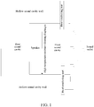
- this embodiment provides a heat-dissipating-type electrical-acoustic conversion apparatus, which comprises a sound outlet, a front sound cavity, a speaker and a rear sound cavity.
- this embodiment adds a heat conducting part which is connected with the front sound cavity, the heat conducting part comprises two portions, one portion is located in the front sound cavity, the other portion is located outside the front sound cavity and is connected to a heat source of the mobile terminal, and the heat conducting part is used for conducting the heat of a heat source in the entire mobile terminal into the front sound cavity; a hollow sound cavity wall is further provided around the speaker and the front sound cavity, a rear sound cavity is formed between the hollow sound cavity wall and the speaker and the front sound cavity, and a portion, outside the front sound cavity, of the heat conducting part passes through the rear sound cavity.
- Contact area between the heat conducting part and the rear sound cavity should be as small as possible, so as to transfer heat to the front sound cavity as much as possible and simultaneously reduce heat loss in the rear sound cavity, such that hot air may be dissipated from the sound outlet as quickly as possible.
- the hollow sound cavity wall may be further provided with a small hole to perform pressure balancing.
- the outer surface of the hollow sound cavity wall to be black, for the complete machine, radiated heat will be adsorbed and more heat radiation may be conducted to the front sound cavity and then is dissipated through the sound outlet.
- the vibrating diaphragm is made of a material with a small heat conductivity coefficient and capable of resisting 160 °C (for a reason that a CPU chip of a mobile phone terminal or a smart phone cannot work normally if the temperature is higher than 150 °C), and preferably, the heat conductivity coefficient of the vibrating diaphragm of the speaker is smaller than 0.2W/(m • K); the sound outlet is used for exhausting the hot air.
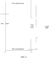
- FIG. 2 shows a main application scenario of the electrical-acoustic conversion apparatus.
- the heat of the heat source is quickly conducted into the front sound cavity through the heat conducting part, convection between external air and internal hot air is accelerated through reciprocating movement of the vibrating diaphragm of the speaker and thus the heat source is quickly cooled.
- the most major problem is the vibration problem of the vibrating diaphragm of the speaker.
- an electric speaker vibrating diaphragm vibrates while sounding.
- how to enable the vibrating diaphragm to vibrate while not sounding to accelerate convectional heat dissipation becomes the major problem.
- the embodiment provides a drive apparatus for a vibrating diaphragm coil of a speaker.
- the drive apparatus comprises:
- the non-audible sound drive circuit comprises an infrasonic drive module and/or an ultrasonic drive module; the infrasonic drive module is used to, after being enabled, drive the vibrating diaphragm coil of the speaker to vibrate and control the vibration frequency of the vibrating diaphragm coil of the speaker to be a human ear non-audible infrasonic frequency; and the ultrasonic drive module is used to, after being enabled, drive the vibrating diaphragm coil of the speaker to vibrate and control the vibration frequency of the vibrating diaphragm coil of the speaker to be a human ear non-audible ultrasonic frequency.
- the infrasonic drive module comprises:
- the amplified single-frequency sinusoidal wave is output to the vibrating diaphragm coil of the speaker and the vibrating diaphragm coil is enabled to vibrate through the current magnitude and current changing frequency of the single-frequency sinusoidal wave.
- the ultrasonic drive module comprises:
- the drive apparatus further comprises an auxiliary coil drive circuit
- the auxiliary coil drive circuit comprises a magnetic steel coil drive circuit and a magnetic steel coil fixed onto a speaker magnetic steel
- the magnetic steel coil drive circuit is used to, after being enabled, convert an input digital control signal into a constant current to output to the magnetic steel coil, generate a magnetic field superposed on an original magnetic steel magnetic field of the vibrating diaphragm coil of the speaker, and make the magnetic field enhance or weaken the original magnetic steel magnetic field of the vibrating diaphragm coil of the speaker by changing a magnitude and a direction of the constant current; when the original magnetic steel magnetic field of the vibrating diaphragm coil of the speaker is enhanced by the magnetic field, a vibration amplitude of the vibrating diaphragm coil of the speaker becomes larger; and when the original magnetic steel magnetic field of the vibrating diaphragm coil of the speaker is weakened by the magnetic field, the vibration amplitude of the vibrating diaphragm coil of the speaker becomes smaller.
- the auxiliary coil drive circuit is an auxiliary circuit for the non-audible sound drive circuit and the audible sound drive circuit, the magnitude and direction of the constant current may be changed by changing the digital control signal, and if the direction of the constant current and the direction of the original magnetic steel magnetic field of the vibrating diaphragm coil of the speaker are the same, the original magnetic field will be enhanced, the stress of the vibrating diaphragm coil of the speaker in the magnetic field will be increased and the vibration amplitude is increased; and contrarily, if the direction of the constant current and the direction of the original magnetic steel magnetic field of the vibrating diaphragm coil of the speaker are opposite, part of the original magnetic field will be counteracted, the magnetic field is weakened, the stress of the vibrating diaphragm coil of the speaker will be decreased and the vibration amplitude will be weakened.
- the auxiliary coil drive circuit specifically comprises:
- the embodiment provides a heat dissipating apparatus comprising the above-mentioned heat-dissipating-type electrical-acoustic conversion apparatus.
- the heat dissipating apparatus comprises: a control unit and the above-mentioned audible sound drive circuit and the non-audible sound drive circuit connected with the control unit, wherein the audible sound drive circuit and the non-audible sound drive circuit are respectively connected with the vibrating diaphragm coil.
- the control unit is used to judge a working state of the speaker, output an enabling signal to trigger the audible sound drive circuit to work if the speaker is in a sounding state, and output an enabling signal to trigger the non-audible sound drive circuit to work if the speaker is in a non-sounding state;
- the audible sound drive circuit is used to, after being enabled by the control unit, amplify a received audio signal and then drive the vibrating diaphragm coil of the speaker to vibrate;
- the non-audible sound drive circuit is used to, after being enabled by the control unit, drive the vibrating diaphragm coil of the speaker to vibrate and control the vibration frequency of the vibrating diaphragm coil to be a human ear non-audible ultrasonic or infrasonic frequency.
- the vibrating diaphragm coil may vibrate to push air to move back and forth under the drive of the audible sound drive circuit or the non-audible sound drive circuit, so as to exhaust hot air from the sound outlet.
- the heat dissipating apparatus further comprises a sensor connected with the control unit, wherein:
- the senor is further used to acquire a heat dissipating state of the complete machine and transmit the heat dissipating state to the control unit;
- the control unit is further used to, when judging that the internal temperature of the mobile terminal reaches the first threshold and is smaller lower than a second threshold, transmit an enabling signal to trigger the infrasonic drive module to work if the speaker is in the non-sounding state; and when the internal temperature of the mobile terminal exceeds the second threshold, judge whether the heat dissipating state of the complete machine acquired by the sensor is normal, and transmit an enabling signal to trigger the ultrasonic drive module to work if the heat dissipating state is normal, wherein the second threshold is larger than the first threshold; the infrasonic drive module is used to, after being enabled by the control unit, drive the vibrating diaphragm coil of the speaker to vibrate, and control the vibration frequency of the vibrating diaphragm coil of the speaker to be a human ear non-audible infra
- the embodiment further provides a mobile terminal comprising the heat dissipating apparatus described above.
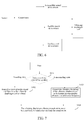
- the embodiment further provides a heat dissipating method of a terminal, adopting the above-mentioned heat dissipating apparatus and comprising the following steps: In S101, a working state of the speaker is judged; if the speaker is in a sounding state, step S102 is executed; and if the speaker is in a non-sounding state, step S103 is executed.
- a received audio signal is amplified and then the vibrating diaphragm coil is driven to vibrate.
- the vibration frequency of the vibrating diaphragm coil is controlled to be a human ear non-audible ultrasonic or infrasonic frequency;
- the vibrating diaphragm coil vibrates to push air to move back and forth to exhaust hot air from the sound outlet.
- the method further comprises: before judging the working state of the speaker, it is to acquire an internal temperature of the mobile terminal, judge whether the internal temperature of the mobile terminal reaches a first threshold, and turn on a heat dissipating mode if the internal temperature of the mobile terminal reaches the first threshold, and turn off the heat dissipating mode if the internal temperature of the mobile terminal is lower than the first threshold, wherein turning on the heat dissipating mode refers to judging the working state of the speaker and executing subsequent steps, and turning off the heat dissipating mode refers to not controlling or stopping controlling the vibrating diaphragm coil to vibrate if the speaker is in the non-sounding state.
- the vibration frequency of the vibrating diaphragm coil is controlled to be a human ear non-audible infrasonic frequency if the speaker is in the non-sounding state; and when the internal temperature of the mobile terminal exceeds the second threshold, whether a heat dissipating state of the complete machine acquired by the sensor is normal is judged, and the vibration frequency of the vibrating diaphragm coil is controlled to be a human ear non-audible ultrasonic frequency if the heat dissipating state is normal, wherein the second threshold is larger than the first threshold.
- the vibration amplitude of the vibrating diaphragm coil of the speaker may be further controlled by controlling the intensity of the magnetic field, and the method comprises:
- applying a constant current to a magnetic steel coil and changing a magnitude and a direction of the constant current to enhance or weaken an original magnetic steel magnetic field of the vibrating diaphragm coil of the speaker comprises:
- the sensor comprises a 3D sensor, an acceleration sensor and a proximity sensor.
- the vibrating diaphragm of the speaker squeezes air and sounds, heat convection is performed due to the vibration of the vibrating diaphragm, and the non-audible sound response circuit is not necessarily turned on.
- the heat dissipating way specifically comprises:
- step S202 it is to judge whether a speaker sounds; if the speaker sounds, step S203 is executed; and otherwise, step S204 is executed.
- a received audio signal is amplified and then the vibrating diaphragm coil is driven to vibrate.
- step S204 it is to detect whether the internal temperature of the mobile phone is higher than 90 °C; if the internal temperature is not higher than 90 °C, step S205 is executed; and otherwise, step S206 is executed.
- the vibration frequency of the vibrating diaphragm coil is controlled to be a human ear non-audible infrasonic frequency;
- the 3D sensor may sense whether the mobile phone is flatly put on a desk and whether the heat dissipating hole is blocked through a 3D sensor, or the proximity sensor may sense whether the holding position of the mobile phone held by the user blocks the heat dissipating hole during conversation via the mobile phone, or may sense a distance between the user and the heat dissipating hole, make a judgment from the angle view of safety and determine whether the heat dissipating state of the sound outlet of the speaker is normal, i.e., whether the sound outlet may dissipate heat, and after the sensor determines that hot air may be output from the sound outlet of the speaker, the non-audible sound response circuit may output ultrasonic frequency and increase the current in the magnetic steel coil to perform quick heat dissipation.
- the vibration frequency of the vibrating diaphragm coil is controlled to be a human ear non-audible ultrasonic frequency.
- the sensor when detecting that the internal temperature of the mobile phone is lower than 60 °C, the sensor notifies the control unit to turn off the heat dissipating mode, and the control unit does not trigger or stops the non-audible sound drive circuit from working.
- the heat dissipating apparatus for the vibrating diaphragm coil, the heat dissipating apparatus, the mobile terminal comprising the heat dissipating apparatus and the heat dissipating method adopting the mobile terminal provided by the embodiments of the present invention by slightly modifying the structure of the speaker, using the original speaker and the sound outlet in the mobile terminal as the heat dissipating structure, using the sound outlet as the heat dissipating hole, using the vibration of the vibrating diaphragm when the speaker in the sounding sate and controlling the vibration frequency of the vibrating diaphragm of the speaker to be human ear non-audible ultrasonic or infrasonic frequency when the speaker is in the non-sounding state, in the present invention, it is to increase air convection and heat exchange, and reduce the temperature of the complete machine to achieve the purpose of heat dissipation, and make it possible to solve the problem
- the embodiments are just preferred embodiments of the present invention and are not used for limiting the protection range of the present invention.
- the present invention may also have other embodiments according to the content of the present invention.
- One skilled in the art can make various corresponding modifications and variations according to the present invention without departing from the scope of the appended claims.
- the electrical-acoustic device by controlling the vibration frequency and amplitude of the vibrating diaphragm and performing reconstruction design on the sound cavity, the electrical-acoustic device is enabled to have electrical-acoustic conversion performance and simultaneously further becomes a heat dissipating device.
- the heat dissipating apparatus not only enables the heat convection transfer way to become possible in the design of the mobile phones, but also enables the structure design and cost control to become simple and feasible.
- the users by solving the problem of heat emission of the mobile phones, not only can the service life of the mobile phones be prolonged, but also the user safety is guaranteed and the user experience is improved.
Landscapes
- Physics & Mathematics (AREA)
- Engineering & Computer Science (AREA)
- Acoustics & Sound (AREA)
- Signal Processing (AREA)
- Audible-Bandwidth Dynamoelectric Transducers Other Than Pickups (AREA)
- Circuit For Audible Band Transducer (AREA)
- Apparatuses For Generation Of Mechanical Vibrations (AREA)
- Cooling Or The Like Of Electrical Apparatus (AREA)
Claims (9)
- Wärmeableitende Vorrichtung, die in einem mobilen Endgerät enthalten ist, wobei die wärmeableitende Vorrichtung einen Klangauslass, einen Sensor, eine Steuereinheit, eine Treibervorrichtung, einen vorderen Klanghohlraum und einen Lautsprecher umfasst, wobei der Lautsprecher eine Schwingungsmembranspule umfasst, wobei die Treibervorrichtung umfasst:eine akustische Klangtreiberschaltung, die konfiguriert ist, um, nachdem sie aktiviert worden ist, ein empfangenes Audiosignal zu verstärken und dann die Schwingungsmembranspule des Lautsprechers zum Schwingen anzutreiben; undeine nichtakustische Klangtreiberschaltung;wobei die akustische Klangtreiberschaltung und die nichtakustische Klangtreiberschaltung jeweils mit der Steuereinheit und der Schwingungsmembranspule verbunden sind,wobei die nichtakustische Klangtreiberschaltung ein Ultraschalltreibermodul umfasst,wobei die Steuereinheit konfiguriert ist, um ein aktivierendes Signal an die akustische Klangtreiberschaltung und an das Ultraschalltreibermodul zu senden,das Ultraschalltreibermodul konfiguriert ist, um, nachdem es durch die Steuereinheit aktiviert worden ist, die Schwingungsmembranspule des Lautsprechers zum Schwingen anzutreiben und die Schwingungsfrequenz der Schwingungsmembranspule des Lautsprechers zu steuern, eine für das menschliche Ohr nichtakustische Ultraschallfrequenz zu sein;wobei der Sensor konfiguriert ist, um mit der Steuereinheit verbunden zu werden, eine Innentemperatur des mobilen Endgeräts zu beschaffen und die Innentemperatur an die Steuereinheit zu senden;wobei die Steuereinheit ferner konfiguriert ist, um zu beurteilen, ob die Innentemperatur des mobilen Endgeräts einen ersten und einen zweiten Schwellenwert erreicht; wobei der zweite Schwellenwert größer als der erste Schwellenwert ist, dadurch gekennzeichnet, dassdie nichtakustische Klangtreiberschaltung ferner ein Infraschalltreibermodul umfasst,die Steuereinheit konfiguriert ist, um ein aktivierendes Signal an das Infraschalltreibermodul zu senden;das Infraschalltreibermodul konfiguriert ist, um, nachdem es durch die Steuereinheit aktiviert worden ist, die Schwingungsmembranspule des Lautsprechers zum Schwingen anzutreiben und die Schwingungsfrequenz der Schwingungsmembranspule des Lautsprechers zu steuern, eine für das menschliche Ohr nichtakustische Infraschallfrequenz zu sein;die Steuereinheit ferner konfiguriert ist, um zu beurteilen, ob der Lautsprecher in einem Klangzustand oder Nicht-Klangzustand ist,der Sensor ferner einen 3D-Sensor und einen Beschleunigungssensor und einen Näherungssensor umfasst und konfiguriert ist, um einen wärmeableitenden Zustand des Klangauslasses zu beschaffen und den wärmeableitenden Zustand an die Steuereinheit zu senden,wobei das Beschaffen des wärmeableitenden Zustands des Klangauslasses das Erfassen, ob das mobile Endgerät flach auf einem Tisch liegt und ob der Klangauslass durch einen 3D-Sensor blockiert ist, oder das Erfassen, ob die Halteposition des mobilen Endgeräts durch einen Benutzer den Klangauslass blockiert, oder das Erfassen eines Abstands zwischen dem Benutzer und dem Klangauslass umfasst,die Steuereinheit ferner konfiguriert ist, um, wenn beurteilt wird, dass die Innentemperatur des mobilen Endgeräts den ersten Schwellenwert erreicht und niedriger als ein zweiter Schwellenwert ist, ein aktivierendes Signal zu senden, um zu bewirken, dass das Infraschalltreibermodul arbeitet, wenn der Lautsprecher in dem Nicht-Klangzustand ist;wenn beurteilt wird, dass die Innentemperatur des mobilen Endgeräts den zweiten Schwellenwert übersteigt, zu beurteilen, ob der Klangauslass Wärme basierend auf dem wärmeableitenden Zustand des Klangauslasses, welcher durch den Sensor beschafft wird, ableiten kann, ein aktivierendes Signal an das Ultraschalltreibermodul zu senden, wenn der Klangauslass Wärme ableiten kann, und das aktivierende Signal an das Infraschalltreibermodul zu senden, wenn der Klangauslass keine Wärme ableiten kann,wenn beurteilt wird, dass die Innentemperatur des mobilen Endgeräts niedriger als der erste Schwellenwert ist und wenn der Lautsprecher in einem Nicht-Klangzustand ist, das aktivierende Signal nicht an das Infraschalltreibermodul und das Ultraschalltreibermodul zu senden oder das Arbeiten des Infraschalltreibermoduls und des Ultraschalltreibermoduls zu beenden.
- Wärmeableitende Vorrichtung nach Anspruch 1, wobei die wärmeableitende Vorrichtung ferner eine Hilfsspulentreiberschaltung umfasst, wobei:die Steuereinheit ferner konfiguriert ist, um ein aktivierendes Signal an die Hilfsspulentreiberschaltung zu senden, um zu bewirken, dass die Hilfsspulentreiberschaltung arbeitet;die Hilfsspulentreiberschaltung konfiguriert ist, um mit der Steuereinheit verbunden zu werden, nachdem sie durch die Steuereinheit aktiviert worden ist, ein digitales Eingabesteuersignal in einen konstanten Strom zum Ausgeben an eine Magnetstahlspule umzuwandeln, ein Magnetfeld zu erzeugen, das ein ursprüngliches Magnetstahlmagnetfeld der Schwingungsmembranspule des Lautsprechers überlagert, und zu veranlassen, dass das Magnetfeld das ursprüngliche Magnetstahlmagnetfeld der Schwingungsmembranspule des Lautsprechers durch Verändern einer Größenordnung und einer Richtung des konstanten Stroms verstärkt oder abschwächt; wobei, wenn das ursprüngliche Magnetstahlmagnetfeld der Schwingungsmembranspule des Lautsprechers durch das Magnetfeld verstärkt wird, eine Schwingungsamplitude der Schwingungsmembranspule des Lautsprechers größer wird; und wenn das ursprüngliche Magnetstahlmagnetfeld der Schwingungsmembranspule des Lautsprechers durch das Magnetfeld abgeschwächt wird, die Schwingungsamplitude der Schwingungsmembranspule des Lautsprechers kleiner wird.
- Wärmeableitende Vorrichtung nach Anspruch 1, wobei die wärmeableitende Vorrichtung ferner konfiguriert ist, um einen wärmeleitenden Teil, der mit dem vorderen Klanghohlraum verbunden ist, hinzuzufügen, wobei der wärmeleitende Teil zwei miteinander verbindende Abschnitte umfasst, wobei ein Abschnitt in dem vorderen Klanghohlraum angeordnet ist und der andere Abschnitt außerhalb des vorderen Klanghohlraums angeordnet ist und mit einer Wärmequelle des mobilen Endgeräts verbunden ist,
und wobei
ein Wärmeleitfähigkeitskoeffizient einer Schwingungsmembran des Lautsprechers kleiner als 0,2W/(m • K) ist. - Wärmeableitende Vorrichtung nach Anspruch 3, wobei eine hohle Klanghohlraumwand ferner um den Lautsprecher und den vorderen Klanghohlraum vorgesehen ist, ein hinterer Klanghohlraum zwischen der hohlen Klanghohlraumwand und dem Lautsprecher und dem vorderen Klanghohlraum ausgebildet ist und ein Abschnitt, außerhalb des vorderen Klanghohlraums, des wärmeleitenden Teils durch den hinteren Klanghohlraum verläuft,
und wobei
eine Außenfläche der hohlen Klanghohlraumwand schwarz beschichtet ist. - Wärmeableitende Vorrichtung nach Anspruch 1, wobei das Infraschalltreibermodul umfasst:einen Rechteckwellensignalgenerator, der konfiguriert ist, um eine Frequenzteilungsverarbeitung an einem Eingangstakt, CLK,-Signal durchzuführen, ein Rechteckwellensignal mit einer Infraschallfrequenz zu generieren und das Rechteckwellensignal an ein Grundwellenfilter auszugeben;wobei das Grundwellenfilter konfiguriert ist, um das Eingangsrechteckwellensignal zu filtern, eine sinusförmige Einzelfrequenzwelle zu generieren und die sinusförmige Einzelfrequenzwelle an einen Niederfrequenz-Leistungsverstärker mit hoher Verstärkung auszugeben;undder Niederfrequenz-Leistungsverstärker mit hoher Verstärkung konfiguriert ist, um, nachdem er aktiviert worden ist, die sinusförmige Einzelfrequenzwelle zu verstärken und dann die Schwingungsmembranspule des Lautsprechers zum Schwingen anzutreiben.
- Wärmeableitende Vorrichtung nach Anspruch 1, wobei das Ultraschalltreibermodul umfasst:einen Rechteckwellensignalgenerator, der konfiguriert ist, um eine Frequenzdoppelungsverarbeitung an einem Eingangstakt, CLK,-Signal durchzuführen, ein Rechteckwellensignal mit einer Ultraschallfrequenz zu generieren und das Rechteckwellensignal an ein Hochfrequenzfilter auszugeben;wobei das Hochfrequenzfilter konfiguriert ist, um das Eingangsrechteckwellensignal zu filtern, eine sinusförmige Einzelfrequenzwelle zu generieren und die sinusförmige Einzelfrequenzwelle an einen Hochfrequenz-Leistungsverstärker mit hoher Verstärkung auszugeben;undder Hochfrequenz-Leistungsverstärker mit hoher Verstärkung konfiguriert ist, um, nachdem er aktiviert worden ist, die sinusförmige Einzelfrequenzwelle zu verstärken und dann die Schwingungsmembranspule des Lautsprechers zum Schwingen anzutreiben.
- Mobiles Endgerät, umfassend die wärmeableitende Vorrichtung nach einem der Ansprüche 1-6.
- Wärmeableitendes Verfahren für eine wärmeableitende Vorrichtung, die in einem mobilen Endgerät enthalten ist, nach Anspruch 1, wobei das wärmeableitende Verfahren umfasst:Beschaffen einer Innentemperatur des mobilen Endgeräts, Beurteilen, ob die Innentemperatur des mobilen Endgeräts einen ersten und einen zweiten Schwellenwert erreicht, wobei der zweite Schwellenwert größer als der erste Schwellenwert ist;dadurch gekennzeichnet, dassdas Verfahren ferner umfasst:Beurteilen, ob ein Lautsprecher des mobilen Endgeräts in einem Klangzustand oder in einem Nicht-Klangzustand ist;Beschaffen eines wärmeableitenden Zustands eines Klangauslasses des mobilen Endgeräts, wobei das Beschaffen des wärmeableitenden Zustands des Klangauslasses das Erfassen, ob das mobile Endgerät flach auf einem Tisch liegt und ob der Klangauslass durch einen 3D-Sensor blockiert ist, oder das Erfassen, ob die Halteposition des mobilen Endgeräts durch einen Benutzer den Klangauslass blockiert, oder das Erfassen eines Abstands zwischen dem Benutzer und dem Klangauslass umfasst,wenn beurteilt wird, dass die Innentemperatur des mobilen Endgeräts den ersten Schwellenwert erreicht und niedriger als ein zweiter Schwellenwert ist, Senden eines aktivierenden Signals an ein Infraschalltreibermodul, um die Schwingungsfrequenz einer Schwingungsmembranspule des Lautsprechers zu steuern, eine für das menschliche Ohr nichtakustische Infraschallfrequenz zu sein, wenn der Lautsprecher in dem Nicht-Klangzustand ist;wenn beurteilt wird, dass die Innentemperatur des mobilen Endgeräts den zweiten Schwellenwert übersteigt, Beurteilen, ob der Klangauslass Wärme basierend auf dem wärmeableitenden Zustand des Klangauslasses ableiten kann, Senden eines aktivierenden Signals an ein Ultraschalltreibermodul, um die Schwingungsfrequenz der Schwingungsmembranspule des Lautsprechers zu steuern, eine für das menschliche Ohr nichtakustische Ultraschallfrequenz zu sein, wenn der Klangauslass Wärme ableiten kann, und Senden des aktivierenden Signals an das Infraschalltreibermodul, um die Schwingungsfrequenz der Schwingungsmembranspule des Lautsprechers zu steuern, eine für das menschliche Ohr nichtakustische Infraschallfrequenz zu sein, wenn der Klangauslass keine Wärme ableiten kann,wenn beurteilt wird, dass die Innentemperatur des mobilen Endgeräts niedriger als der erste Schwellenwert ist und wenn der Lautsprecher in einem Nicht-Klangzustand ist und wenn der Lautsprecher in dem Nicht-Klangzustand ist, Nicht-Senden des aktivierenden Signals an das Infraschalltreibermodul und das Ultraschalltreibermodul oder Beenden des Arbeitens des Infraschalltreibermoduls und des Ultraschalltreibermoduls.
- Verfahren nach Anspruch 8, ferner umfassend:Anbringen eines konstanten Stroms an eine Magnetstahlspule und Verändern einer Größenordnung und einer Richtung des konstanten Stroms, um ein ursprüngliches Magnetstahlmagnetfeld der Schwingungsmembranspule des Lautsprechers zu verstärken oder abzuschwächen,wobei, wenn das ursprüngliche Magnetstahlmagnetfeld der Schwingungsmembranspule des Lautsprechers verstärkt wird, eine Schwingungsamplitude der Schwingungsmembranspule des Lautsprechers größer wird; und wenn das ursprüngliche Magnetstahlmagnetfeld der Schwingungsmembranspule des Lautsprechers abgeschwächt wird, die Schwingungsamplitude der Schwingungsmembranspule des Lautsprechers kleiner wird,und wobeidas Anbringen eines konstanten Stroms an eine Magnetstahlspule und das Verändern einer Größenordnung und einer Richtung des konstanten Stroms, um ein ursprüngliches Magnetstahlmagnetfeld derSchwingungsmembranspule des Lautsprechers zu verstärken oder abzuschwächen, umfasst:Eingeben eines digitalen Steuersignal, Umwandeln des digitalen Steuersignals in einen konstanten Strom zum Ausgeben an die Magnetstahlmagnetspule und Erzeugen eines Magnetfelds, das ein ursprüngliches Magnetstahlmagnetfeld der Schwingungsmembranspule des Lautsprechers überlagert, undVerändern des digitalen Steuersignals, um die Größenordnung und die Richtung des konstanten Stroms zu verändern, um zu veranlassen, dass das Magnetfeld das ursprüngliche Magnetstahlmagnetfeld der Schwingungsmembranspule des Lautsprechers verstärkt oder abschwächt.
Applications Claiming Priority (2)
| Application Number | Priority Date | Filing Date | Title |
|---|---|---|---|
| CN201310703429.2A CN104735949B (zh) | 2013-12-19 | 2013-12-19 | 喇叭振膜线圈的驱动装置、散热装置、方法及移动终端 |
| PCT/CN2014/078110 WO2015089992A1 (zh) | 2013-12-19 | 2014-05-22 | 喇叭振膜线圈的驱动装置、散热装置、方法及移动终端 |
Publications (3)
| Publication Number | Publication Date |
|---|---|
| EP3068202A1 EP3068202A1 (de) | 2016-09-14 |
| EP3068202A4 EP3068202A4 (de) | 2016-12-07 |
| EP3068202B1 true EP3068202B1 (de) | 2019-02-06 |
Family
ID=53402036
Family Applications (1)
| Application Number | Title | Priority Date | Filing Date |
|---|---|---|---|
| EP14872793.6A Not-in-force EP3068202B1 (de) | 2013-12-19 | 2014-05-22 | Ansteuerungsvorrichtung, wärmeableitende vorrichtung und verfahren für eine schwingende lautsprecher-membranspule sowie mobiles endgerät |
Country Status (5)
| Country | Link |
|---|---|
| US (1) | US9900701B2 (de) |
| EP (1) | EP3068202B1 (de) |
| JP (1) | JP6246371B2 (de) |
| CN (1) | CN104735949B (de) |
| WO (1) | WO2015089992A1 (de) |
Families Citing this family (48)
| Publication number | Priority date | Publication date | Assignee | Title |
|---|---|---|---|---|
| CN104902358B (zh) * | 2015-06-08 | 2019-01-18 | 歌尔股份有限公司 | 一种扬声器模组 |
| CN105159424A (zh) * | 2015-09-11 | 2015-12-16 | 小米科技有限责任公司 | 散热结构以及散热方法、装置和移动设备 |
| CN105430124B (zh) * | 2015-10-28 | 2019-03-05 | 努比亚技术有限公司 | 一种终端及散热方法 |
| CN205788067U (zh) * | 2016-05-04 | 2016-12-07 | 中兴通讯股份有限公司 | 移动终端 |
| CN106060729B (zh) * | 2016-06-27 | 2020-03-24 | 联想(北京)有限公司 | 一种控制方法及电子设备 |
| US10101962B2 (en) * | 2016-06-28 | 2018-10-16 | Cirrus Logic, Inc. | User input through transducer |
| KR20180010866A (ko) * | 2016-07-22 | 2018-01-31 | 엘지전자 주식회사 | 이동 단말기 |
| CN106162391A (zh) * | 2016-08-09 | 2016-11-23 | 青岛海信移动通信技术股份有限公司 | 移动终端 |
| US10721837B2 (en) | 2016-11-18 | 2020-07-21 | Lg Electronics Inc. | Mobile terminal |
| CN106657504A (zh) * | 2016-12-26 | 2017-05-10 | 天津商业大学 | 一种手机散热保护套 |
| CN106686500B (zh) * | 2016-12-29 | 2020-11-03 | 维沃移动通信有限公司 | 一种对移动终端进行散热的方法、装置和移动终端 |
| CN106658331A (zh) * | 2016-12-30 | 2017-05-10 | 维沃移动通信有限公司 | 一种喇叭的检测方法及移动终端 |
| US10290302B2 (en) | 2016-12-30 | 2019-05-14 | Google Llc | Compact home assistant with combined acoustic waveguide and heat sink |
| CN107046669B (zh) * | 2017-03-03 | 2020-08-21 | Oppo广东移动通信有限公司 | 电子装置和基于温度的检测方法 |
| WO2018163700A1 (ja) * | 2017-03-07 | 2018-09-13 | ソニー株式会社 | コンテンツ提示システム、コンテンツ提示装置及び風提示装置 |
| US20200154193A1 (en) * | 2017-04-21 | 2020-05-14 | Hewlett-Packard Development Company, L.P. | Signal modifier for self-cooling headsets |
| EP3574656A4 (de) * | 2017-04-21 | 2020-11-18 | Hewlett-Packard Development Company, L.P. | Lautsprecherkonusmembranen für selbstkühlende kopfhörer |
| CN106982538A (zh) * | 2017-05-09 | 2017-07-25 | 合肥淘云科技有限公司 | 一种带喇叭电子产品的散热方法和散热装置 |
| US10419855B2 (en) * | 2017-11-30 | 2019-09-17 | Apple Inc. | Cooling for audio appliances |
| CN110636407B (zh) * | 2018-06-21 | 2024-06-07 | 刘云轩 | 一种全数字扬声器系统及其工作方法 |
| CN112291688A (zh) * | 2019-07-22 | 2021-01-29 | 瑞声科技(新加坡)有限公司 | 扬声器箱及移动终端 |
| CN112261554A (zh) * | 2019-07-22 | 2021-01-22 | 瑞声科技(新加坡)有限公司 | 扬声器装置及具有该扬声器装置的移动终端 |
| CN210093444U (zh) * | 2019-07-22 | 2020-02-18 | 瑞声科技(新加坡)有限公司 | 扬声器装置及具有该扬声器装置的移动终端 |
| CN112291645A (zh) * | 2019-07-22 | 2021-01-29 | 瑞声科技(新加坡)有限公司 | 扬声器装置及移动终端 |
| CN210168068U (zh) * | 2019-07-22 | 2020-03-20 | 瑞声科技(新加坡)有限公司 | 发声装置和移动终端 |
| CN110475184B (zh) * | 2019-07-23 | 2021-02-26 | 瑞声科技(新加坡)有限公司 | 发声装置和移动终端 |
| US11553265B2 (en) | 2019-07-24 | 2023-01-10 | Google Llc | Compact home assistant having a controlled sound path |
| US11079875B2 (en) | 2019-07-24 | 2021-08-03 | Google Llc | Compact home assistant having touch sensitive housing |
| CN110740405B (zh) * | 2019-11-04 | 2025-01-21 | 南京中感微电子有限公司 | 一种集成式音频处理芯片 |
| WO2021114146A1 (zh) * | 2019-12-11 | 2021-06-17 | 瑞声声学科技(深圳)有限公司 | 热管和扬声器装置 |
| CN111308220B (zh) * | 2020-02-28 | 2025-07-01 | 北京华科仪科技股份有限公司 | 一种电磁式电导率传感器的激励电路 |
| CN113727248B (zh) * | 2020-05-26 | 2024-12-03 | 北京小米移动软件有限公司 | 扬声器播放音频的方法、装置及介质 |
| CN113765496A (zh) * | 2020-06-04 | 2021-12-07 | 中兴通讯股份有限公司 | 散热组件、散热结构以及散热方法、电子设备和装置 |
| CN113965850B (zh) * | 2020-07-02 | 2024-01-26 | 上海艾为电子技术股份有限公司 | 扬声器振膜位移控制电路和控制方法、电子设备 |
| CN114125089B (zh) * | 2020-08-31 | 2024-09-10 | 北京小米移动软件有限公司 | 终端设备、信号处理方法和装置、存储介质 |
| JP7617752B2 (ja) * | 2021-01-29 | 2025-01-20 | ニデックインスツルメンツ株式会社 | アクチュエータ |
| CN113432706B (zh) * | 2021-06-04 | 2022-02-11 | 北京大学 | 一种片上集成的声矢量梯度传感器芯片及其实现方法 |
| CN113597222A (zh) * | 2021-08-09 | 2021-11-02 | 北京小米移动软件有限公司 | 显示设备 |
| KR20230023372A (ko) * | 2021-08-10 | 2023-02-17 | 삼성전자주식회사 | 표면 발열을 제어하기 위한 전자 장치 및 그 전자 장치에서의 동작 방법 |
| US12510942B2 (en) | 2021-08-10 | 2025-12-30 | Samsung Electronics Co., Ltd. | Electronic device for controlling surface heat and method of operating the electronic device |
| TWI797753B (zh) | 2021-09-22 | 2023-04-01 | 仁寶電腦工業股份有限公司 | 利用揚聲器散熱之發聲裝置及其適用之控制方法 |
| CN115942164A (zh) * | 2021-09-22 | 2023-04-07 | 仁宝电脑工业股份有限公司 | 利用扬声器散热的发声装置及其适用的控制方法 |
| CN115996262B (zh) * | 2021-10-18 | 2024-09-03 | 北京小米移动软件有限公司 | 终端、温度调整方法、装置及存储介质 |
| TWI786895B (zh) * | 2021-10-20 | 2022-12-11 | 大陸商美律電子(深圳)有限公司 | 電子裝置 |
| CN116263611A (zh) * | 2021-12-14 | 2023-06-16 | 北京小米移动软件有限公司 | 终端设备温度的调节方法、装置、电子设备及存储介质 |
| US12105569B2 (en) * | 2022-01-18 | 2024-10-01 | Dell Products, L.P. | Low temp power state handling |
| CN118354250A (zh) * | 2024-06-16 | 2024-07-16 | 时新(上海)产品设计有限公司 | 散热耳机 |
| CN119155597A (zh) * | 2024-09-10 | 2024-12-17 | 广东保伦电子股份有限公司 | 一种低频声音信号的发送、接收方法及系统 |
Family Cites Families (20)
| Publication number | Priority date | Publication date | Assignee | Title |
|---|---|---|---|---|
| JPH03260554A (ja) * | 1990-03-09 | 1991-11-20 | Matsushita Electric Ind Co Ltd | 温風送風装置 |
| JP2522184B2 (ja) | 1993-10-28 | 1996-08-07 | 日本電気株式会社 | ディジタルスピ―カ |
| US6123145A (en) * | 1995-06-12 | 2000-09-26 | Georgia Tech Research Corporation | Synthetic jet actuators for cooling heated bodies and environments |
| JP3816960B2 (ja) * | 1997-05-15 | 2006-08-30 | 松下電工株式会社 | 超音波機器 |
| ID25920A (id) * | 1998-01-08 | 2000-11-09 | Sanyo Electric Co | Peralatan peringatan dan sistem komunikasi tanpa kabel yang mengandungnya |
| GB9813513D0 (en) | 1998-06-24 | 1998-08-19 | British Gas Plc | Synthesising a sine wave |
| US6678387B2 (en) * | 2001-10-30 | 2004-01-13 | Alpine Electronics, Inc. | Loudspeaker having cooling system |
| JP4501409B2 (ja) * | 2003-10-31 | 2010-07-14 | ソニー株式会社 | 放熱装置及び電子機器 |
| CN1634669A (zh) * | 2003-12-31 | 2005-07-06 | 杜鹏 | 一种共用一个振荡源的超大功率超声波发生器 |
| EP1696696A1 (de) * | 2005-02-28 | 2006-08-30 | Sony Ericsson Mobile Communications AB | Tragbares Funk-kommunikationsgerät mit einer Luftpumpe |
| CN100504721C (zh) * | 2006-09-28 | 2009-06-24 | 广达电脑股份有限公司 | 散热装置 |
| US8390437B2 (en) * | 2008-04-25 | 2013-03-05 | Google Inc. | Ultrasonic vibrator |
| CN102223590B (zh) * | 2010-04-14 | 2014-04-09 | 财团法人工业技术研究院 | 具有散热结构的平面式扬声器及平面扬声器的散热方法 |
| CN201708915U (zh) * | 2010-05-28 | 2011-01-12 | 深圳Tcl新技术有限公司 | 一种散热装置 |
| WO2012114158A1 (en) * | 2011-02-25 | 2012-08-30 | Nokia Corporation | Method and apparatus for thermoacoustic cooling |
| US20130108099A1 (en) * | 2011-10-31 | 2013-05-02 | Jason Kemmerer | Loudspeaker having improved cooling system integrally formed on speaker frame |
| JP2013251829A (ja) | 2012-06-04 | 2013-12-12 | Jvc Kenwood Corp | 音声処理装置および音声処理装置の水濡れ判定方法 |
| CN103857257B (zh) * | 2012-11-28 | 2017-04-19 | 联想(北京)有限公司 | 一种电子设备及电子设备散热方法 |
| CN203181218U (zh) * | 2013-04-10 | 2013-09-04 | 成都摩宝网络科技有限公司 | 一种用于音频手机支付的超音频发生器 |
| US9354677B2 (en) * | 2013-09-26 | 2016-05-31 | Sonos, Inc. | Speaker cooling |
-
2013
- 2013-12-19 CN CN201310703429.2A patent/CN104735949B/zh not_active Expired - Fee Related
-
2014
- 2014-05-22 JP JP2016539130A patent/JP6246371B2/ja not_active Expired - Fee Related
- 2014-05-22 EP EP14872793.6A patent/EP3068202B1/de not_active Not-in-force
- 2014-05-22 US US15/103,869 patent/US9900701B2/en not_active Expired - Fee Related
- 2014-05-22 WO PCT/CN2014/078110 patent/WO2015089992A1/zh not_active Ceased
Non-Patent Citations (1)
| Title |
|---|
| None * |
Also Published As
| Publication number | Publication date |
|---|---|
| US20160323673A1 (en) | 2016-11-03 |
| JP6246371B2 (ja) | 2017-12-13 |
| EP3068202A4 (de) | 2016-12-07 |
| JP2017501866A (ja) | 2017-01-19 |
| WO2015089992A1 (zh) | 2015-06-25 |
| US9900701B2 (en) | 2018-02-20 |
| EP3068202A1 (de) | 2016-09-14 |
| CN104735949B (zh) | 2019-02-05 |
| CN104735949A (zh) | 2015-06-24 |
Similar Documents
| Publication | Publication Date | Title |
|---|---|---|
| EP3068202B1 (de) | Ansteuerungsvorrichtung, wärmeableitende vorrichtung und verfahren für eine schwingende lautsprecher-membranspule sowie mobiles endgerät | |
| US10425738B2 (en) | Evacuation of liquid from acoustic space | |
| CN106162391A (zh) | 移动终端 | |
| CN108901006A (zh) | 一种无线耳机配对的方法和电子设备 | |
| CN111787201B (zh) | 电子设备、摄像模组的散热控制方法和散热控制装置 | |
| WO2020078233A1 (zh) | 壳体结构、移动终端及移动终端的声音调节方法 | |
| KR102205835B1 (ko) | 마이크로 스피커 및 이를 포함하는 전자 장치 | |
| US9565505B2 (en) | Loudspeaker cone excursion estimation using reference signal | |
| WO2017190454A1 (zh) | 移动终端 | |
| CN105284127A (zh) | 声音产生器 | |
| US20210051411A1 (en) | Dual loudspeaker enabled cooling | |
| CN111405829A (zh) | 散热结构、方法及终端 | |
| US9723398B2 (en) | Speaker | |
| WO2020107603A1 (zh) | 屏幕发声装置以及电子设备 | |
| CN205693881U (zh) | 一种扬声器系统及移动终端 | |
| CN113347307B (zh) | 抑制漏音方法、相关设备及计算机可读存储介质 | |
| CN111885466B (zh) | 扬声器结构及电子设备 | |
| CN205584489U (zh) | 一种扬声器模组及移动终端 | |
| CN203722986U (zh) | 一种移动终端 | |
| CN115550820B (zh) | 扬声器控制方法、装置、电子设备及存储介质 | |
| WO2021114144A1 (zh) | 热管及扬声器装置 | |
| WO2021012206A1 (zh) | 扬声器箱及移动终端 | |
| CN117896660A (zh) | 扬声器模组及终端设备 | |
| CN110138031A (zh) | 一种无线充电器及电子产品组件 | |
| CN211152196U (zh) | 音腔装置以及移动终端 |
Legal Events
| Date | Code | Title | Description |
|---|---|---|---|
| PUAI | Public reference made under article 153(3) epc to a published international application that has entered the european phase |
Free format text: ORIGINAL CODE: 0009012 |
|
| 17P | Request for examination filed |
Effective date: 20160610 |
|
| AK | Designated contracting states |
Kind code of ref document: A1 Designated state(s): AL AT BE BG CH CY CZ DE DK EE ES FI FR GB GR HR HU IE IS IT LI LT LU LV MC MK MT NL NO PL PT RO RS SE SI SK SM TR |
|
| AX | Request for extension of the european patent |
Extension state: BA ME |
|
| A4 | Supplementary search report drawn up and despatched |
Effective date: 20161109 |
|
| RIC1 | Information provided on ipc code assigned before grant |
Ipc: B06B 1/00 20060101ALI20161103BHEP Ipc: G06F 1/20 20060101AFI20161103BHEP Ipc: H04R 9/02 20060101ALI20161103BHEP Ipc: H04R 9/06 20060101ALN20161103BHEP |
|
| DAX | Request for extension of the european patent (deleted) | ||
| STAA | Information on the status of an ep patent application or granted ep patent |
Free format text: STATUS: EXAMINATION IS IN PROGRESS |
|
| 17Q | First examination report despatched |
Effective date: 20180222 |
|
| REG | Reference to a national code |
Ref country code: DE Ref legal event code: R079 Ref document number: 602014040876 Country of ref document: DE Free format text: PREVIOUS MAIN CLASS: H05K0007200000 Ipc: G06F0001200000 |
|
| RIC1 | Information provided on ipc code assigned before grant |
Ipc: H04R 9/06 20060101ALN20180713BHEP Ipc: H04R 9/02 20060101ALI20180713BHEP Ipc: B06B 1/00 20060101ALI20180713BHEP Ipc: G06F 1/20 20060101AFI20180713BHEP |
|
| GRAP | Despatch of communication of intention to grant a patent |
Free format text: ORIGINAL CODE: EPIDOSNIGR1 |
|
| STAA | Information on the status of an ep patent application or granted ep patent |
Free format text: STATUS: GRANT OF PATENT IS INTENDED |
|
| INTG | Intention to grant announced |
Effective date: 20180904 |
|
| GRAS | Grant fee paid |
Free format text: ORIGINAL CODE: EPIDOSNIGR3 |
|
| GRAA | (expected) grant |
Free format text: ORIGINAL CODE: 0009210 |
|
| STAA | Information on the status of an ep patent application or granted ep patent |
Free format text: STATUS: THE PATENT HAS BEEN GRANTED |
|
| AK | Designated contracting states |
Kind code of ref document: B1 Designated state(s): AL AT BE BG CH CY CZ DE DK EE ES FI FR GB GR HR HU IE IS IT LI LT LU LV MC MK MT NL NO PL PT RO RS SE SI SK SM TR |
|
| REG | Reference to a national code |
Ref country code: GB Ref legal event code: FG4D |
|
| REG | Reference to a national code |
Ref country code: CH Ref legal event code: EP Ref country code: AT Ref legal event code: REF Ref document number: 1095310 Country of ref document: AT Kind code of ref document: T Effective date: 20190215 |
|
| REG | Reference to a national code |
Ref country code: IE Ref legal event code: FG4D |
|
| REG | Reference to a national code |
Ref country code: DE Ref legal event code: R096 Ref document number: 602014040876 Country of ref document: DE |
|
| REG | Reference to a national code |
Ref country code: NL Ref legal event code: MP Effective date: 20190206 |
|
| REG | Reference to a national code |
Ref country code: LT Ref legal event code: MG4D |
|
| PG25 | Lapsed in a contracting state [announced via postgrant information from national office to epo] |
Ref country code: PT Free format text: LAPSE BECAUSE OF FAILURE TO SUBMIT A TRANSLATION OF THE DESCRIPTION OR TO PAY THE FEE WITHIN THE PRESCRIBED TIME-LIMIT Effective date: 20190606 Ref country code: LT Free format text: LAPSE BECAUSE OF FAILURE TO SUBMIT A TRANSLATION OF THE DESCRIPTION OR TO PAY THE FEE WITHIN THE PRESCRIBED TIME-LIMIT Effective date: 20190206 Ref country code: NL Free format text: LAPSE BECAUSE OF FAILURE TO SUBMIT A TRANSLATION OF THE DESCRIPTION OR TO PAY THE FEE WITHIN THE PRESCRIBED TIME-LIMIT Effective date: 20190206 Ref country code: FI Free format text: LAPSE BECAUSE OF FAILURE TO SUBMIT A TRANSLATION OF THE DESCRIPTION OR TO PAY THE FEE WITHIN THE PRESCRIBED TIME-LIMIT Effective date: 20190206 Ref country code: NO Free format text: LAPSE BECAUSE OF FAILURE TO SUBMIT A TRANSLATION OF THE DESCRIPTION OR TO PAY THE FEE WITHIN THE PRESCRIBED TIME-LIMIT Effective date: 20190506 Ref country code: SE Free format text: LAPSE BECAUSE OF FAILURE TO SUBMIT A TRANSLATION OF THE DESCRIPTION OR TO PAY THE FEE WITHIN THE PRESCRIBED TIME-LIMIT Effective date: 20190206 |
|
| REG | Reference to a national code |
Ref country code: AT Ref legal event code: MK05 Ref document number: 1095310 Country of ref document: AT Kind code of ref document: T Effective date: 20190206 |
|
| PG25 | Lapsed in a contracting state [announced via postgrant information from national office to epo] |
Ref country code: BG Free format text: LAPSE BECAUSE OF FAILURE TO SUBMIT A TRANSLATION OF THE DESCRIPTION OR TO PAY THE FEE WITHIN THE PRESCRIBED TIME-LIMIT Effective date: 20190506 Ref country code: GR Free format text: LAPSE BECAUSE OF FAILURE TO SUBMIT A TRANSLATION OF THE DESCRIPTION OR TO PAY THE FEE WITHIN THE PRESCRIBED TIME-LIMIT Effective date: 20190507 Ref country code: RS Free format text: LAPSE BECAUSE OF FAILURE TO SUBMIT A TRANSLATION OF THE DESCRIPTION OR TO PAY THE FEE WITHIN THE PRESCRIBED TIME-LIMIT Effective date: 20190206 Ref country code: IS Free format text: LAPSE BECAUSE OF FAILURE TO SUBMIT A TRANSLATION OF THE DESCRIPTION OR TO PAY THE FEE WITHIN THE PRESCRIBED TIME-LIMIT Effective date: 20190606 Ref country code: LV Free format text: LAPSE BECAUSE OF FAILURE TO SUBMIT A TRANSLATION OF THE DESCRIPTION OR TO PAY THE FEE WITHIN THE PRESCRIBED TIME-LIMIT Effective date: 20190206 Ref country code: HR Free format text: LAPSE BECAUSE OF FAILURE TO SUBMIT A TRANSLATION OF THE DESCRIPTION OR TO PAY THE FEE WITHIN THE PRESCRIBED TIME-LIMIT Effective date: 20190206 |
|
| PG25 | Lapsed in a contracting state [announced via postgrant information from national office to epo] |
Ref country code: IT Free format text: LAPSE BECAUSE OF FAILURE TO SUBMIT A TRANSLATION OF THE DESCRIPTION OR TO PAY THE FEE WITHIN THE PRESCRIBED TIME-LIMIT Effective date: 20190206 Ref country code: RO Free format text: LAPSE BECAUSE OF FAILURE TO SUBMIT A TRANSLATION OF THE DESCRIPTION OR TO PAY THE FEE WITHIN THE PRESCRIBED TIME-LIMIT Effective date: 20190206 Ref country code: SK Free format text: LAPSE BECAUSE OF FAILURE TO SUBMIT A TRANSLATION OF THE DESCRIPTION OR TO PAY THE FEE WITHIN THE PRESCRIBED TIME-LIMIT Effective date: 20190206 Ref country code: CZ Free format text: LAPSE BECAUSE OF FAILURE TO SUBMIT A TRANSLATION OF THE DESCRIPTION OR TO PAY THE FEE WITHIN THE PRESCRIBED TIME-LIMIT Effective date: 20190206 Ref country code: AL Free format text: LAPSE BECAUSE OF FAILURE TO SUBMIT A TRANSLATION OF THE DESCRIPTION OR TO PAY THE FEE WITHIN THE PRESCRIBED TIME-LIMIT Effective date: 20190206 Ref country code: DK Free format text: LAPSE BECAUSE OF FAILURE TO SUBMIT A TRANSLATION OF THE DESCRIPTION OR TO PAY THE FEE WITHIN THE PRESCRIBED TIME-LIMIT Effective date: 20190206 Ref country code: ES Free format text: LAPSE BECAUSE OF FAILURE TO SUBMIT A TRANSLATION OF THE DESCRIPTION OR TO PAY THE FEE WITHIN THE PRESCRIBED TIME-LIMIT Effective date: 20190206 Ref country code: EE Free format text: LAPSE BECAUSE OF FAILURE TO SUBMIT A TRANSLATION OF THE DESCRIPTION OR TO PAY THE FEE WITHIN THE PRESCRIBED TIME-LIMIT Effective date: 20190206 |
|
| REG | Reference to a national code |
Ref country code: DE Ref legal event code: R097 Ref document number: 602014040876 Country of ref document: DE |
|
| PG25 | Lapsed in a contracting state [announced via postgrant information from national office to epo] |
Ref country code: SM Free format text: LAPSE BECAUSE OF FAILURE TO SUBMIT A TRANSLATION OF THE DESCRIPTION OR TO PAY THE FEE WITHIN THE PRESCRIBED TIME-LIMIT Effective date: 20190206 Ref country code: PL Free format text: LAPSE BECAUSE OF FAILURE TO SUBMIT A TRANSLATION OF THE DESCRIPTION OR TO PAY THE FEE WITHIN THE PRESCRIBED TIME-LIMIT Effective date: 20190206 |
|
| PLBE | No opposition filed within time limit |
Free format text: ORIGINAL CODE: 0009261 |
|
| STAA | Information on the status of an ep patent application or granted ep patent |
Free format text: STATUS: NO OPPOSITION FILED WITHIN TIME LIMIT |
|
| REG | Reference to a national code |
Ref country code: CH Ref legal event code: PL |
|
| PG25 | Lapsed in a contracting state [announced via postgrant information from national office to epo] |
Ref country code: AT Free format text: LAPSE BECAUSE OF FAILURE TO SUBMIT A TRANSLATION OF THE DESCRIPTION OR TO PAY THE FEE WITHIN THE PRESCRIBED TIME-LIMIT Effective date: 20190206 |
|
| 26N | No opposition filed |
Effective date: 20191107 |
|
| PG25 | Lapsed in a contracting state [announced via postgrant information from national office to epo] |
Ref country code: CH Free format text: LAPSE BECAUSE OF NON-PAYMENT OF DUE FEES Effective date: 20190531 Ref country code: MC Free format text: LAPSE BECAUSE OF FAILURE TO SUBMIT A TRANSLATION OF THE DESCRIPTION OR TO PAY THE FEE WITHIN THE PRESCRIBED TIME-LIMIT Effective date: 20190206 Ref country code: LI Free format text: LAPSE BECAUSE OF NON-PAYMENT OF DUE FEES Effective date: 20190531 |
|
| REG | Reference to a national code |
Ref country code: BE Ref legal event code: MM Effective date: 20190531 |
|
| PG25 | Lapsed in a contracting state [announced via postgrant information from national office to epo] |
Ref country code: SI Free format text: LAPSE BECAUSE OF FAILURE TO SUBMIT A TRANSLATION OF THE DESCRIPTION OR TO PAY THE FEE WITHIN THE PRESCRIBED TIME-LIMIT Effective date: 20190206 Ref country code: LU Free format text: LAPSE BECAUSE OF NON-PAYMENT OF DUE FEES Effective date: 20190522 |
|
| PG25 | Lapsed in a contracting state [announced via postgrant information from national office to epo] |
Ref country code: TR Free format text: LAPSE BECAUSE OF FAILURE TO SUBMIT A TRANSLATION OF THE DESCRIPTION OR TO PAY THE FEE WITHIN THE PRESCRIBED TIME-LIMIT Effective date: 20190206 |
|
| PG25 | Lapsed in a contracting state [announced via postgrant information from national office to epo] |
Ref country code: IE Free format text: LAPSE BECAUSE OF NON-PAYMENT OF DUE FEES Effective date: 20190522 |
|
| PG25 | Lapsed in a contracting state [announced via postgrant information from national office to epo] |
Ref country code: BE Free format text: LAPSE BECAUSE OF NON-PAYMENT OF DUE FEES Effective date: 20190531 |
|
| PGFP | Annual fee paid to national office [announced via postgrant information from national office to epo] |
Ref country code: GB Payment date: 20200513 Year of fee payment: 7 |
|
| PGFP | Annual fee paid to national office [announced via postgrant information from national office to epo] |
Ref country code: DE Payment date: 20201031 Year of fee payment: 7 Ref country code: FR Payment date: 20201028 Year of fee payment: 7 |
|
| PG25 | Lapsed in a contracting state [announced via postgrant information from national office to epo] |
Ref country code: CY Free format text: LAPSE BECAUSE OF FAILURE TO SUBMIT A TRANSLATION OF THE DESCRIPTION OR TO PAY THE FEE WITHIN THE PRESCRIBED TIME-LIMIT Effective date: 20190206 |
|
| PG25 | Lapsed in a contracting state [announced via postgrant information from national office to epo] |
Ref country code: MT Free format text: LAPSE BECAUSE OF FAILURE TO SUBMIT A TRANSLATION OF THE DESCRIPTION OR TO PAY THE FEE WITHIN THE PRESCRIBED TIME-LIMIT Effective date: 20190206 Ref country code: HU Free format text: LAPSE BECAUSE OF FAILURE TO SUBMIT A TRANSLATION OF THE DESCRIPTION OR TO PAY THE FEE WITHIN THE PRESCRIBED TIME-LIMIT; INVALID AB INITIO Effective date: 20140522 |
|
| REG | Reference to a national code |
Ref country code: DE Ref legal event code: R119 Ref document number: 602014040876 Country of ref document: DE |
|
| GBPC | Gb: european patent ceased through non-payment of renewal fee |
Effective date: 20210522 |
|
| PG25 | Lapsed in a contracting state [announced via postgrant information from national office to epo] |
Ref country code: GB Free format text: LAPSE BECAUSE OF NON-PAYMENT OF DUE FEES Effective date: 20210522 Ref country code: DE Free format text: LAPSE BECAUSE OF NON-PAYMENT OF DUE FEES Effective date: 20211201 |
|
| PG25 | Lapsed in a contracting state [announced via postgrant information from national office to epo] |
Ref country code: FR Free format text: LAPSE BECAUSE OF NON-PAYMENT OF DUE FEES Effective date: 20210531 |
|
| PG25 | Lapsed in a contracting state [announced via postgrant information from national office to epo] |
Ref country code: MK Free format text: LAPSE BECAUSE OF FAILURE TO SUBMIT A TRANSLATION OF THE DESCRIPTION OR TO PAY THE FEE WITHIN THE PRESCRIBED TIME-LIMIT Effective date: 20190206 |