EP3068730B1 - A percolation filtering device - Google Patents
A percolation filtering device Download PDFInfo
- Publication number
- EP3068730B1 EP3068730B1 EP14799413.1A EP14799413A EP3068730B1 EP 3068730 B1 EP3068730 B1 EP 3068730B1 EP 14799413 A EP14799413 A EP 14799413A EP 3068730 B1 EP3068730 B1 EP 3068730B1
- Authority
- EP
- European Patent Office
- Prior art keywords
- valve
- passage
- valve passage
- extension
- cartridge
- Prior art date
- Legal status (The legal status is an assumption and is not a legal conclusion. Google has not performed a legal analysis and makes no representation as to the accuracy of the status listed.)
- Not-in-force
Links
- 238000001914 filtration Methods 0.000 title claims description 38
- 238000005325 percolation Methods 0.000 title claims description 13
- XLYOFNOQVPJJNP-UHFFFAOYSA-N water Substances O XLYOFNOQVPJJNP-UHFFFAOYSA-N 0.000 claims description 10
- 239000007788 liquid Substances 0.000 claims description 4
- 230000002452 interceptive effect Effects 0.000 claims description 2
- 238000011144 upstream manufacturing Methods 0.000 claims description 2
- 230000000295 complement effect Effects 0.000 claims 2
- 230000001419 dependent effect Effects 0.000 claims 1
- 230000001747 exhibiting effect Effects 0.000 claims 1
- 238000003780 insertion Methods 0.000 description 3
- 230000037431 insertion Effects 0.000 description 3
- 230000000694 effects Effects 0.000 description 2
- 238000007789 sealing Methods 0.000 description 2
- 238000004891 communication Methods 0.000 description 1
- 238000005516 engineering process Methods 0.000 description 1
- 238000004519 manufacturing process Methods 0.000 description 1
- 239000000463 material Substances 0.000 description 1
- 238000000034 method Methods 0.000 description 1
Images




Classifications
-
- C—CHEMISTRY; METALLURGY
- C02—TREATMENT OF WATER, WASTE WATER, SEWAGE, OR SLUDGE
- C02F—TREATMENT OF WATER, WASTE WATER, SEWAGE, OR SLUDGE
- C02F1/00—Treatment of water, waste water, or sewage
- C02F1/001—Processes for the treatment of water whereby the filtration technique is of importance
- C02F1/003—Processes for the treatment of water whereby the filtration technique is of importance using household-type filters for producing potable water, e.g. pitchers, bottles, faucet mounted devices
-
- C—CHEMISTRY; METALLURGY
- C02—TREATMENT OF WATER, WASTE WATER, SEWAGE, OR SLUDGE
- C02F—TREATMENT OF WATER, WASTE WATER, SEWAGE, OR SLUDGE
- C02F2201/00—Apparatus for treatment of water, waste water or sewage
- C02F2201/002—Construction details of the apparatus
- C02F2201/004—Seals, connections
-
- C—CHEMISTRY; METALLURGY
- C02—TREATMENT OF WATER, WASTE WATER, SEWAGE, OR SLUDGE
- C02F—TREATMENT OF WATER, WASTE WATER, SEWAGE, OR SLUDGE
- C02F2201/00—Apparatus for treatment of water, waste water or sewage
- C02F2201/002—Construction details of the apparatus
- C02F2201/005—Valves
-
- C—CHEMISTRY; METALLURGY
- C02—TREATMENT OF WATER, WASTE WATER, SEWAGE, OR SLUDGE
- C02F—TREATMENT OF WATER, WASTE WATER, SEWAGE, OR SLUDGE
- C02F2307/00—Location of water treatment or water treatment device
- C02F2307/04—Location of water treatment or water treatment device as part of a pitcher or jug
Definitions
- the subject of the invention is a percolation filtering device for filtering water and other drinks, of the type comprising a replaceable filtering cartridge.
- Percolation filtering systems are known, typically jug-shaped, with a divider element which divides the jug into a top tank, for collecting water to be filtered, and a bottom tank, for collecting the filtered water.
- the two tanks communicate solely through a channel, in which a filtering cartridge is placed, so that the entire flow passes through it.
- a normally-closed shut-off valve which is driven into the open state, when the filtering cartridge is inserted into the channel, by an enabler element, in general belonging to the filtering cartridge. Examples of this technology are described in international patent applications WO 2009 015679 or WO 2010 081845 .
- the valve is housed inside a passage produced in the divider element downstream of the cartridge.
- the cartridges are provided with a tube-shaped extension which is made to enter the passage until it reaches an operational feature of the valve.
- the valve is made to rotate, with a lever movement, and is brought into the open position.
- valve main purpose for the use of the valve is to prevent liquid from passing to the bottom tank in the event that the filtering cartridge is not positioned or, alternatively, in the event that a cartridge suitable for being used with the specific filtering system is not present.
- the known solutions can easily be tampered with by the user, for example using small pins, or other elastic items, inserted in the valve seat to keep the valve locked in the open position regardless of the presence of the cartridge.
- the aim of the present invention is to provide a percolation filtering device suitable for meeting this requirement, and which at the same time can be produced at low cost.
- the percolation filtering device comprises a radial extension that, opposite to the device disclosed in DE 10 2009 000231 , represents an obstacle to the passage of an enabler element inside the valve passage of the filtering device, as well as to other elements, for the opening of a respective valve member.
- the reference 1 indicates in an overall sense a percolation filtering device including a jug 2, inside of which there is placed a divider element 3 (hopper) which divides the jug 2 into a top tank 4a, for collecting water to be filtered, and a bottom tank 4b, for collecting the filtered water.
- the two tanks 4a,b communicate solely through a channel which forms a seat 5 for receiving a filtering cartridge 6.
- the cartridge 6 has a sealing edge 63 that can be engaged at an entrance opening of the seat, so as to make the water poured into the tank 4a flow into the cartridge.
- the seat 5 has a lateral shell 7 and a base 8 in which a valve passage 9 is open, forming the only opening for discharge from the top tank to the bottom tank.
- the valve passage 9 has a generally cylindrical shape with a sleeve section 10 protruding towards the cartridge 6 where the sleeve section 10 is received in a recess in the form of a cutout 12 of the base 13 of the cartridge.
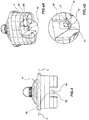
- valve passage 9 is made by means of a separate cylindrical body 10', which can be inserted, for example with slight interference, into the sleeve section 10 of the divider element 3, as can be observed in Figures 5, 5A and 5B .
- valve seat 14 on which there normally sits a valve member 15.
- the valve member 15 has a manoeuvring arm 16 which extends into the passage 9 so that, by acting on the arm 16, it is possible to manoeuvre the valve member 15 into the open state, moving it away from the valve seat 14.
- the passage 9, together with the seat 14 and the associated valve member 15, form a flow shut-off valve which, when enabled, allows the passage of liquid from the top tank 4a to the bottom tank 4b through the filtering cartridge, while preventing communication between the two tanks when the valve is disabled.
- FIG. 5A and 5B illustrate the valve member 14 in the open position, following insertion of the part 60 into the valve passage 9, and in the closed position, respectively.
- the part 60 has a tubular shape and, therefore, by inserting the cartridge into the seat 5, the part enters the passage 9 defined in the sleeve section 10, engaging and turning the manoeuvring arm 16 of the valve member 15 so as to move it away from the valve seat 14.
- Such a part therefore functions as an enabler element 60 of the valve and has the function of interacting with the arm 16 of the valve member 15 (normally closed) housed in the valve passage 9 in order to actuate it into the open position.
- valve passage 9 is illustrated in greater detail.
- the valve passage 9 comprises, at a distal end relative to the cartridge 6, an annular closure portion 17, upon which the valve member 15 can abut with the aim of shutting off the flow of liquid towards the collecting tank 4b.
- the valve seat 14 is therefore defined between this annular portion 17 and a pair of intermediate walls 18, between which there is defined a slot 21, more clearly illustrated in the embodiments of Figures 6, 6A and 6B , through which the manoeuvring arm 16 can pass.
- valve passage 9 Upstream of the intermediate walls 18, and therefore of the valve member 15, the valve passage 9 further comprises an extension 19, which extends, preferably, from an inner wall 10a of the passage 9 towards the central part of the passage 9.
- the extension 19 is developed from an inner wall 10a of the cylindrical body 10' in a radial direction towards an inner region of the valve passage 9.
- the intermediate walls 18 and the extension 19 are produced as a single body with the cylindrical body 10'. Consequently, the fact that the cylindrical body 10' is tightly inserted into the sleeve section 10 of the divider element 3 turns out to be particularly advantageous in that it provides for a high degree of production simplicity and for the use of different materials with respect to the remaining parts of the jug.
- the intermediate walls define an abutting surface 18 suitable for abutting a distal end 62 of the enabler element 60, in such a way as to limit the travel of the enabler element 60 inside the valve passage 9.
- the positioning of a travel stop inside the valve passage 9 turns out to be particularly advantageous in that it avoids the need to produce this feature at the sealing edge 63, therefore avoiding any risk of damaging the same.
- the radial extension 19 is preferably adjacent to the manoeuvring arm 16 and arranged in such a way as not to prevent it from oscillating for the purpose of bringing the valve member 15 into the open position.
- the extension 19 is developed from the inner wall 10a of the valve passage 9 without interfering with the movement of the valve member 15 between its open and closed positions.
- the radial extension 19 represents an obstacle to the passage of the enabler element 60 inside the valve passage 9, as well as to other elements, for the opening of the valve member.
- the cylindrical tubular surface which forms the enabler element 60 exhibits at least one notch 61 of such a shape as to be able to accommodate inside it the radial extension 19, at least for a sufficient portion to reach the manoeuvring arm 16 and open the valve member 15.
- the radial extension 19 exhibits a rectilinear segment shape and the notch 61 is presented as a square slot of complimentary shape.
- the cartridge 6 exhibits a pair of notches 61 arranged in diametrically opposed positions so as to make the insertion of the cartridge 6, or more generally of the enabler element 60, possible in two symmetrical directions.
- the filtering cartridge 6 can comprise an equal number of notches 61, oriented symmetrically with respect to a longitudinal axis of symmetry X of the cartridge, through which axis a longitudinal plane of symmetry of the cartridge passes.
- manoeuvring arm 16 may be reached only by specially shaped enabler elements, therefore making the opening of the valve using other means complicated.
- the radial extension is adjacent to the manoeuvring arm, it follows that the rotation of the latter about a longitudinal axis of the valve passage 9 is substantially prevented or limited.
- the cylindrical and tubular shape of the enabler element also provides for the possibility of providing a calibrated passage 20, formed by a widening on the inlet edge of the of the valve passage 9, which, once the enabler element 60 is inserted therein, allows the flow of water towards the bottom tank 4b to be appropriately controlled, by defining a constriction of very precise dimensions.
- the calibrated passage 20 is formed at a collar 11 produced at an entry end of the sleeve section 10, i.e. the end proximal, when in use, to the cartridge 6.
- the collar 11 exhibits an inlet section that substantially coincides with that of the enabler element 60, in such a way that the only passage between the top tank 4a and the bottom tank 4b is defined by the calibrated passage 20, in such a way as to allow the flow of filtered water to be controlled according to a method that is known per se.
- the notch 61 exhibits a longitudinal extension I that is shorter with respect to the distance d between the collar 11 and the intermediate wall 18.
- the extension 19 is comprised within an axial development of the valve passage 9 and, more preferably, entirely downstream of the collar 11.
- the presence of the notch 61 provides for giving a certain radial elasticity to the enabler element 60, therefore facilitating insertion into the passage 9.
- the ratio between the abovementioned lengths I and d provides for achieving the desired flow control effect.
- the passage 20 may have dimensions so as not to represent a constriction, the flow controller part being arranged on the cartridge itself.
- Figures 6A, 6B and 7A, 7B represent variant embodiments of the valve passage 9 according to the present invention, which are distinguished from one another by the positions and number of radial extensions.
- Figures 6B and 7B provides for the radial extension to extend over an entire sector of the circumference defining the passage 9 and, as can be observed in Figure 8 , the notch 61 on the cartridge 6 exhibits a shape that is complimentary to it.
- FIG. 9A and 9B A further embodiment non according to the invention is described in Figures 9A and 9B , in which it can be observed how the same inventive principles can also be applied to axial-opening valves.
- the opening of the valve member 15' takes place by pushing the manoeuvring arm 16' downwards by means of the enabler element 60, the features of which are similar to those of the previous embodiments.
Landscapes
- Life Sciences & Earth Sciences (AREA)
- Hydrology & Water Resources (AREA)
- Engineering & Computer Science (AREA)
- Environmental & Geological Engineering (AREA)
- Water Supply & Treatment (AREA)
- Chemical & Material Sciences (AREA)
- Organic Chemistry (AREA)
- Water Treatment By Sorption (AREA)
- Processing Of Solid Wastes (AREA)
Priority Applications (1)
| Application Number | Priority Date | Filing Date | Title |
|---|---|---|---|
| PL14799413T PL3068730T3 (pl) | 2013-11-14 | 2014-11-14 | Urządzenie filtrujące przesączające |
Applications Claiming Priority (2)
| Application Number | Priority Date | Filing Date | Title |
|---|---|---|---|
| IT000308A ITPD20130308A1 (it) | 2013-11-14 | 2013-11-14 | Dispositivo filtrante a percolazione |
| PCT/EP2014/074616 WO2015071415A1 (en) | 2013-11-14 | 2014-11-14 | A percolation filtering device |
Publications (2)
| Publication Number | Publication Date |
|---|---|
| EP3068730A1 EP3068730A1 (en) | 2016-09-21 |
| EP3068730B1 true EP3068730B1 (en) | 2019-06-12 |
Family
ID=49958592
Family Applications (1)
| Application Number | Title | Priority Date | Filing Date |
|---|---|---|---|
| EP14799413.1A Not-in-force EP3068730B1 (en) | 2013-11-14 | 2014-11-14 | A percolation filtering device |
Country Status (4)
| Country | Link |
|---|---|
| EP (1) | EP3068730B1 (pl) |
| IT (1) | ITPD20130308A1 (pl) |
| PL (1) | PL3068730T3 (pl) |
| WO (1) | WO2015071415A1 (pl) |
Cited By (3)
| Publication number | Priority date | Publication date | Assignee | Title |
|---|---|---|---|---|
| WO2025215119A1 (de) * | 2024-04-12 | 2025-10-16 | Sodapop Gmbh | Ventilöffner, filterkartusche und filtervorrichtung |
| WO2025215118A1 (de) * | 2024-04-12 | 2025-10-16 | Sodapop Gmbh | Filterkartusche, system und filtervorrichtung |
| WO2025223850A1 (de) * | 2024-04-24 | 2025-10-30 | Sodapop Gmbh | Ventilöffner und filtervorrichtung zum aufbereiten von flüssigkeiten |
Families Citing this family (3)
| Publication number | Priority date | Publication date | Assignee | Title |
|---|---|---|---|---|
| IT201700047102A1 (it) * | 2017-05-02 | 2018-11-02 | Laica Spa | Elemento per l’abilitazione di una valvola di intercettazione di flusso in sistemi filtranti a cartuccia sostituibile |
| NL2020073B1 (en) | 2017-12-12 | 2019-06-19 | Itrec Bv | Marine j-lay pipelaying system and method |
| DE102020005634A1 (de) * | 2020-09-15 | 2022-03-17 | Christoph Götz | Instandhaltungsset für eine Tischwasserfiltervorrichtung |
Family Cites Families (3)
| Publication number | Priority date | Publication date | Assignee | Title |
|---|---|---|---|---|
| JP5007892B2 (ja) * | 2007-07-31 | 2012-08-22 | ライカ・エス・ピー・エー | 濾過システム |
| DE102009000231B4 (de) | 2009-01-14 | 2020-11-19 | Brita Gmbh | Ventilbetätigungseinrichtung eines Ventils, Flüssigkeitsbehälter einer Flüssigkeitsbehandlungsvorrichtung, Flüssigkeitsbehandlungsvorrichtung sowie Verwendung einer solchen Vorrichtung |
| ITPD20110185A1 (it) * | 2011-06-07 | 2012-12-08 | Laica Spa | Kit per l'abilitazione della valvola di intercettazione di flusso nei sistemi filtranti a cartuccia sostituibile |
-
2013
- 2013-11-14 IT IT000308A patent/ITPD20130308A1/it unknown
-
2014
- 2014-11-14 EP EP14799413.1A patent/EP3068730B1/en not_active Not-in-force
- 2014-11-14 WO PCT/EP2014/074616 patent/WO2015071415A1/en not_active Ceased
- 2014-11-14 PL PL14799413T patent/PL3068730T3/pl unknown
Non-Patent Citations (1)
| Title |
|---|
| None * |
Cited By (3)
| Publication number | Priority date | Publication date | Assignee | Title |
|---|---|---|---|---|
| WO2025215119A1 (de) * | 2024-04-12 | 2025-10-16 | Sodapop Gmbh | Ventilöffner, filterkartusche und filtervorrichtung |
| WO2025215118A1 (de) * | 2024-04-12 | 2025-10-16 | Sodapop Gmbh | Filterkartusche, system und filtervorrichtung |
| WO2025223850A1 (de) * | 2024-04-24 | 2025-10-30 | Sodapop Gmbh | Ventilöffner und filtervorrichtung zum aufbereiten von flüssigkeiten |
Also Published As
| Publication number | Publication date |
|---|---|
| PL3068730T3 (pl) | 2020-01-31 |
| WO2015071415A1 (en) | 2015-05-21 |
| ITPD20130308A1 (it) | 2015-05-15 |
| EP3068730A1 (en) | 2016-09-21 |
Similar Documents
| Publication | Publication Date | Title |
|---|---|---|
| EP3068730B1 (en) | A percolation filtering device | |
| EP2718232B1 (en) | Kit for enabling a flow shut-off valve in replaceable cartridge filter systems | |
| US20180333690A1 (en) | Measuring Adapter Assembly for Closed Loop Fluid Transfer System | |
| EP3552641A2 (en) | Extraction system from a closed loop system | |
| RU2634340C2 (ru) | Клапан разности давления с промыванием | |
| US20150076174A1 (en) | Dispensing device for fluids from a fluid container | |
| KR20160046289A (ko) | Iv 유량 조절기 | |
| EP1968883B1 (en) | Lock-out device and method | |
| KR20170050576A (ko) | 유로전환밸브 및 이를 구비한 수처리장치 | |
| KR20180048029A (ko) | 여과기능 조절이 가능한 샤워기 | |
| CN102389246A (zh) | 饮料用容器的栓体 | |
| EP3886972B1 (en) | Check valve with integrated filter | |
| US20120074343A1 (en) | tap | |
| AU2017215431B2 (en) | Foot valve for drip chambers of medical infusion or transfusion apparatuses | |
| EP3634913B1 (en) | Percolation-type filtration device | |
| KR101732503B1 (ko) | 직수형 정수기 | |
| EP2658418A1 (en) | Collecting bowl for liquids of a device for processing liquids | |
| EP1164982A1 (en) | A tap | |
| EP2542130B1 (en) | A device for disabling flow shut-off selector members for percolating filter systems and a kit including said device | |
| EP2565163A1 (en) | Fluid treatment system | |
| EP2101123B1 (en) | A water disconnector unit, in particular for controlling the supply of water to a water circuit of a boiler | |
| US10788142B2 (en) | Blocking mechanism for a stopcock manifold | |
| EP1768534B1 (en) | Coffee percolator | |
| EP3164288A1 (en) | Removal prevention device for anti-siphoning devices for tanks | |
| EP3458408A1 (en) | Measuring adapter assembly for closed loop fluid transfer system |
Legal Events
| Date | Code | Title | Description |
|---|---|---|---|
| PUAI | Public reference made under article 153(3) epc to a published international application that has entered the european phase |
Free format text: ORIGINAL CODE: 0009012 |
|
| 17P | Request for examination filed |
Effective date: 20160429 |
|
| AK | Designated contracting states |
Kind code of ref document: A1 Designated state(s): AL AT BE BG CH CY CZ DE DK EE ES FI FR GB GR HR HU IE IS IT LI LT LU LV MC MK MT NL NO PL PT RO RS SE SI SK SM TR |
|
| AX | Request for extension of the european patent |
Extension state: BA ME |
|
| DAX | Request for extension of the european patent (deleted) | ||
| STAA | Information on the status of an ep patent application or granted ep patent |
Free format text: STATUS: EXAMINATION IS IN PROGRESS |
|
| 17Q | First examination report despatched |
Effective date: 20171219 |
|
| GRAP | Despatch of communication of intention to grant a patent |
Free format text: ORIGINAL CODE: EPIDOSNIGR1 |
|
| STAA | Information on the status of an ep patent application or granted ep patent |
Free format text: STATUS: GRANT OF PATENT IS INTENDED |
|
| INTG | Intention to grant announced |
Effective date: 20190201 |
|
| GRAS | Grant fee paid |
Free format text: ORIGINAL CODE: EPIDOSNIGR3 |
|
| GRAA | (expected) grant |
Free format text: ORIGINAL CODE: 0009210 |
|
| STAA | Information on the status of an ep patent application or granted ep patent |
Free format text: STATUS: THE PATENT HAS BEEN GRANTED |
|
| AK | Designated contracting states |
Kind code of ref document: B1 Designated state(s): AL AT BE BG CH CY CZ DE DK EE ES FI FR GB GR HR HU IE IS IT LI LT LU LV MC MK MT NL NO PL PT RO RS SE SI SK SM TR |
|
| REG | Reference to a national code |
Ref country code: GB Ref legal event code: FG4D |
|
| REG | Reference to a national code |
Ref country code: CH Ref legal event code: EP |
|
| REG | Reference to a national code |
Ref country code: AT Ref legal event code: REF Ref document number: 1142339 Country of ref document: AT Kind code of ref document: T Effective date: 20190615 |
|
| REG | Reference to a national code |
Ref country code: DE Ref legal event code: R096 Ref document number: 602014048304 Country of ref document: DE |
|
| REG | Reference to a national code |
Ref country code: IE Ref legal event code: FG4D |
|
| REG | Reference to a national code |
Ref country code: NL Ref legal event code: MP Effective date: 20190612 |
|
| REG | Reference to a national code |
Ref country code: LT Ref legal event code: MG4D |
|
| PG25 | Lapsed in a contracting state [announced via postgrant information from national office to epo] |
Ref country code: HR Free format text: LAPSE BECAUSE OF FAILURE TO SUBMIT A TRANSLATION OF THE DESCRIPTION OR TO PAY THE FEE WITHIN THE PRESCRIBED TIME-LIMIT Effective date: 20190612 Ref country code: LT Free format text: LAPSE BECAUSE OF FAILURE TO SUBMIT A TRANSLATION OF THE DESCRIPTION OR TO PAY THE FEE WITHIN THE PRESCRIBED TIME-LIMIT Effective date: 20190612 Ref country code: FI Free format text: LAPSE BECAUSE OF FAILURE TO SUBMIT A TRANSLATION OF THE DESCRIPTION OR TO PAY THE FEE WITHIN THE PRESCRIBED TIME-LIMIT Effective date: 20190612 Ref country code: NO Free format text: LAPSE BECAUSE OF FAILURE TO SUBMIT A TRANSLATION OF THE DESCRIPTION OR TO PAY THE FEE WITHIN THE PRESCRIBED TIME-LIMIT Effective date: 20190912 Ref country code: SE Free format text: LAPSE BECAUSE OF FAILURE TO SUBMIT A TRANSLATION OF THE DESCRIPTION OR TO PAY THE FEE WITHIN THE PRESCRIBED TIME-LIMIT Effective date: 20190612 Ref country code: AL Free format text: LAPSE BECAUSE OF FAILURE TO SUBMIT A TRANSLATION OF THE DESCRIPTION OR TO PAY THE FEE WITHIN THE PRESCRIBED TIME-LIMIT Effective date: 20190612 |
|
| PG25 | Lapsed in a contracting state [announced via postgrant information from national office to epo] |
Ref country code: LV Free format text: LAPSE BECAUSE OF FAILURE TO SUBMIT A TRANSLATION OF THE DESCRIPTION OR TO PAY THE FEE WITHIN THE PRESCRIBED TIME-LIMIT Effective date: 20190612 Ref country code: GR Free format text: LAPSE BECAUSE OF FAILURE TO SUBMIT A TRANSLATION OF THE DESCRIPTION OR TO PAY THE FEE WITHIN THE PRESCRIBED TIME-LIMIT Effective date: 20190913 Ref country code: BG Free format text: LAPSE BECAUSE OF FAILURE TO SUBMIT A TRANSLATION OF THE DESCRIPTION OR TO PAY THE FEE WITHIN THE PRESCRIBED TIME-LIMIT Effective date: 20190912 Ref country code: RS Free format text: LAPSE BECAUSE OF FAILURE TO SUBMIT A TRANSLATION OF THE DESCRIPTION OR TO PAY THE FEE WITHIN THE PRESCRIBED TIME-LIMIT Effective date: 20190612 |
|
| PG25 | Lapsed in a contracting state [announced via postgrant information from national office to epo] |
Ref country code: PT Free format text: LAPSE BECAUSE OF FAILURE TO SUBMIT A TRANSLATION OF THE DESCRIPTION OR TO PAY THE FEE WITHIN THE PRESCRIBED TIME-LIMIT Effective date: 20191014 Ref country code: CZ Free format text: LAPSE BECAUSE OF FAILURE TO SUBMIT A TRANSLATION OF THE DESCRIPTION OR TO PAY THE FEE WITHIN THE PRESCRIBED TIME-LIMIT Effective date: 20190612 Ref country code: RO Free format text: LAPSE BECAUSE OF FAILURE TO SUBMIT A TRANSLATION OF THE DESCRIPTION OR TO PAY THE FEE WITHIN THE PRESCRIBED TIME-LIMIT Effective date: 20190612 Ref country code: NL Free format text: LAPSE BECAUSE OF FAILURE TO SUBMIT A TRANSLATION OF THE DESCRIPTION OR TO PAY THE FEE WITHIN THE PRESCRIBED TIME-LIMIT Effective date: 20190612 Ref country code: EE Free format text: LAPSE BECAUSE OF FAILURE TO SUBMIT A TRANSLATION OF THE DESCRIPTION OR TO PAY THE FEE WITHIN THE PRESCRIBED TIME-LIMIT Effective date: 20190612 Ref country code: SK Free format text: LAPSE BECAUSE OF FAILURE TO SUBMIT A TRANSLATION OF THE DESCRIPTION OR TO PAY THE FEE WITHIN THE PRESCRIBED TIME-LIMIT Effective date: 20190612 |
|
| PG25 | Lapsed in a contracting state [announced via postgrant information from national office to epo] |
Ref country code: IT Free format text: LAPSE BECAUSE OF FAILURE TO SUBMIT A TRANSLATION OF THE DESCRIPTION OR TO PAY THE FEE WITHIN THE PRESCRIBED TIME-LIMIT Effective date: 20190612 Ref country code: ES Free format text: LAPSE BECAUSE OF FAILURE TO SUBMIT A TRANSLATION OF THE DESCRIPTION OR TO PAY THE FEE WITHIN THE PRESCRIBED TIME-LIMIT Effective date: 20190612 Ref country code: IS Free format text: LAPSE BECAUSE OF FAILURE TO SUBMIT A TRANSLATION OF THE DESCRIPTION OR TO PAY THE FEE WITHIN THE PRESCRIBED TIME-LIMIT Effective date: 20191012 Ref country code: SM Free format text: LAPSE BECAUSE OF FAILURE TO SUBMIT A TRANSLATION OF THE DESCRIPTION OR TO PAY THE FEE WITHIN THE PRESCRIBED TIME-LIMIT Effective date: 20190612 |
|
| REG | Reference to a national code |
Ref country code: DE Ref legal event code: R097 Ref document number: 602014048304 Country of ref document: DE |
|
| PG25 | Lapsed in a contracting state [announced via postgrant information from national office to epo] |
Ref country code: TR Free format text: LAPSE BECAUSE OF FAILURE TO SUBMIT A TRANSLATION OF THE DESCRIPTION OR TO PAY THE FEE WITHIN THE PRESCRIBED TIME-LIMIT Effective date: 20190612 |
|
| PLBE | No opposition filed within time limit |
Free format text: ORIGINAL CODE: 0009261 |
|
| STAA | Information on the status of an ep patent application or granted ep patent |
Free format text: STATUS: NO OPPOSITION FILED WITHIN TIME LIMIT |
|
| PG25 | Lapsed in a contracting state [announced via postgrant information from national office to epo] |
Ref country code: DK Free format text: LAPSE BECAUSE OF FAILURE TO SUBMIT A TRANSLATION OF THE DESCRIPTION OR TO PAY THE FEE WITHIN THE PRESCRIBED TIME-LIMIT Effective date: 20190612 |
|
| 26N | No opposition filed |
Effective date: 20200313 |
|
| PG25 | Lapsed in a contracting state [announced via postgrant information from national office to epo] |
Ref country code: SI Free format text: LAPSE BECAUSE OF FAILURE TO SUBMIT A TRANSLATION OF THE DESCRIPTION OR TO PAY THE FEE WITHIN THE PRESCRIBED TIME-LIMIT Effective date: 20190612 Ref country code: IS Free format text: LAPSE BECAUSE OF FAILURE TO SUBMIT A TRANSLATION OF THE DESCRIPTION OR TO PAY THE FEE WITHIN THE PRESCRIBED TIME-LIMIT Effective date: 20200224 |
|
| PG2D | Information on lapse in contracting state deleted |
Ref country code: IS |
|
| PG25 | Lapsed in a contracting state [announced via postgrant information from national office to epo] |
Ref country code: LU Free format text: LAPSE BECAUSE OF NON-PAYMENT OF DUE FEES Effective date: 20191114 Ref country code: MC Free format text: LAPSE BECAUSE OF FAILURE TO SUBMIT A TRANSLATION OF THE DESCRIPTION OR TO PAY THE FEE WITHIN THE PRESCRIBED TIME-LIMIT Effective date: 20190612 |
|
| REG | Reference to a national code |
Ref country code: BE Ref legal event code: MM Effective date: 20191130 |
|
| REG | Reference to a national code |
Ref country code: AT Ref legal event code: UEP Ref document number: 1142339 Country of ref document: AT Kind code of ref document: T Effective date: 20190612 |
|
| PG25 | Lapsed in a contracting state [announced via postgrant information from national office to epo] |
Ref country code: IE Free format text: LAPSE BECAUSE OF NON-PAYMENT OF DUE FEES Effective date: 20191114 |
|
| PG25 | Lapsed in a contracting state [announced via postgrant information from national office to epo] |
Ref country code: BE Free format text: LAPSE BECAUSE OF NON-PAYMENT OF DUE FEES Effective date: 20191130 |
|
| PGFP | Annual fee paid to national office [announced via postgrant information from national office to epo] |
Ref country code: FR Payment date: 20201120 Year of fee payment: 7 Ref country code: GB Payment date: 20201120 Year of fee payment: 7 Ref country code: DE Payment date: 20201119 Year of fee payment: 7 Ref country code: CH Payment date: 20201118 Year of fee payment: 7 Ref country code: AT Payment date: 20201119 Year of fee payment: 7 |
|
| PGFP | Annual fee paid to national office [announced via postgrant information from national office to epo] |
Ref country code: PL Payment date: 20201106 Year of fee payment: 7 |
|
| PG25 | Lapsed in a contracting state [announced via postgrant information from national office to epo] |
Ref country code: CY Free format text: LAPSE BECAUSE OF FAILURE TO SUBMIT A TRANSLATION OF THE DESCRIPTION OR TO PAY THE FEE WITHIN THE PRESCRIBED TIME-LIMIT Effective date: 20190612 |
|
| PG25 | Lapsed in a contracting state [announced via postgrant information from national office to epo] |
Ref country code: HU Free format text: LAPSE BECAUSE OF FAILURE TO SUBMIT A TRANSLATION OF THE DESCRIPTION OR TO PAY THE FEE WITHIN THE PRESCRIBED TIME-LIMIT; INVALID AB INITIO Effective date: 20141114 Ref country code: MT Free format text: LAPSE BECAUSE OF FAILURE TO SUBMIT A TRANSLATION OF THE DESCRIPTION OR TO PAY THE FEE WITHIN THE PRESCRIBED TIME-LIMIT Effective date: 20190612 |
|
| REG | Reference to a national code |
Ref country code: DE Ref legal event code: R119 Ref document number: 602014048304 Country of ref document: DE |
|
| PG25 | Lapsed in a contracting state [announced via postgrant information from national office to epo] |
Ref country code: MK Free format text: LAPSE BECAUSE OF FAILURE TO SUBMIT A TRANSLATION OF THE DESCRIPTION OR TO PAY THE FEE WITHIN THE PRESCRIBED TIME-LIMIT Effective date: 20190612 |
|
| REG | Reference to a national code |
Ref country code: CH Ref legal event code: PL |
|
| REG | Reference to a national code |
Ref country code: AT Ref legal event code: MM01 Ref document number: 1142339 Country of ref document: AT Kind code of ref document: T Effective date: 20211114 |
|
| GBPC | Gb: european patent ceased through non-payment of renewal fee |
Effective date: 20211114 |
|
| PG25 | Lapsed in a contracting state [announced via postgrant information from national office to epo] |
Ref country code: LI Free format text: LAPSE BECAUSE OF NON-PAYMENT OF DUE FEES Effective date: 20211130 Ref country code: CH Free format text: LAPSE BECAUSE OF NON-PAYMENT OF DUE FEES Effective date: 20211130 Ref country code: AT Free format text: LAPSE BECAUSE OF NON-PAYMENT OF DUE FEES Effective date: 20211114 |
|
| PG25 | Lapsed in a contracting state [announced via postgrant information from national office to epo] |
Ref country code: GB Free format text: LAPSE BECAUSE OF NON-PAYMENT OF DUE FEES Effective date: 20211114 Ref country code: DE Free format text: LAPSE BECAUSE OF NON-PAYMENT OF DUE FEES Effective date: 20220601 |
|
| PG25 | Lapsed in a contracting state [announced via postgrant information from national office to epo] |
Ref country code: FR Free format text: LAPSE BECAUSE OF NON-PAYMENT OF DUE FEES Effective date: 20211130 |
|
| PG25 | Lapsed in a contracting state [announced via postgrant information from national office to epo] |
Ref country code: PL Free format text: LAPSE BECAUSE OF NON-PAYMENT OF DUE FEES Effective date: 20211114 |