EP3068962B1 - Système de chaînage pour panneaux de béton isolés - Google Patents
Système de chaînage pour panneaux de béton isolés Download PDFInfo
- Publication number
- EP3068962B1 EP3068962B1 EP14869437.5A EP14869437A EP3068962B1 EP 3068962 B1 EP3068962 B1 EP 3068962B1 EP 14869437 A EP14869437 A EP 14869437A EP 3068962 B1 EP3068962 B1 EP 3068962B1
- Authority
- EP
- European Patent Office
- Prior art keywords
- tie
- insulation layer
- hub
- hubs
- concrete
- Prior art date
- Legal status (The legal status is an assumption and is not a legal conclusion. Google has not performed a legal analysis and makes no representation as to the accuracy of the status listed.)
- Active
Links
Images






Classifications
-
- E—FIXED CONSTRUCTIONS
- E04—BUILDING
- E04C—STRUCTURAL ELEMENTS; BUILDING MATERIALS
- E04C5/00—Reinforcing elements, e.g. for concrete; Auxiliary elements therefor
- E04C5/16—Auxiliary parts for reinforcements, e.g. connectors, spacers, stirrups
- E04C5/162—Connectors or means for connecting parts for reinforcements
-
- E—FIXED CONSTRUCTIONS
- E04—BUILDING
- E04C—STRUCTURAL ELEMENTS; BUILDING MATERIALS
- E04C2/00—Building elements of relatively thin form for the construction of parts of buildings, e.g. sheet materials, slabs, or panels
- E04C2/02—Building elements of relatively thin form for the construction of parts of buildings, e.g. sheet materials, slabs, or panels characterised by specified materials
- E04C2/26—Building elements of relatively thin form for the construction of parts of buildings, e.g. sheet materials, slabs, or panels characterised by specified materials composed of materials covered by two or more of groups E04C2/04, E04C2/08, E04C2/10 or of materials covered by one of these groups with a material not specified in one of the groups
- E04C2/284—Building elements of relatively thin form for the construction of parts of buildings, e.g. sheet materials, slabs, or panels characterised by specified materials composed of materials covered by two or more of groups E04C2/04, E04C2/08, E04C2/10 or of materials covered by one of these groups with a material not specified in one of the groups at least one of the materials being insulating
- E04C2/288—Building elements of relatively thin form for the construction of parts of buildings, e.g. sheet materials, slabs, or panels characterised by specified materials composed of materials covered by two or more of groups E04C2/04, E04C2/08, E04C2/10 or of materials covered by one of these groups with a material not specified in one of the groups at least one of the materials being insulating composed of insulating material and concrete, stone or stone-like material
-
- E—FIXED CONSTRUCTIONS
- E04—BUILDING
- E04C—STRUCTURAL ELEMENTS; BUILDING MATERIALS
- E04C2/00—Building elements of relatively thin form for the construction of parts of buildings, e.g. sheet materials, slabs, or panels
- E04C2/30—Building elements of relatively thin form for the construction of parts of buildings, e.g. sheet materials, slabs, or panels characterised by the shape or structure
- E04C2/34—Building elements of relatively thin form for the construction of parts of buildings, e.g. sheet materials, slabs, or panels characterised by the shape or structure composed of two or more spaced sheet-like parts
-
- E—FIXED CONSTRUCTIONS
- E04—BUILDING
- E04B—GENERAL BUILDING CONSTRUCTIONS; WALLS, e.g. PARTITIONS; ROOFS; FLOORS; CEILINGS; INSULATION OR OTHER PROTECTION OF BUILDINGS
- E04B1/00—Constructions in general; Structures which are not restricted either to walls, e.g. partitions, or floors or ceilings or roofs
- E04B1/38—Connections for building structures in general
- E04B1/41—Connecting devices specially adapted for embedding in concrete or masonry
-
- E—FIXED CONSTRUCTIONS
- E04—BUILDING
- E04C—STRUCTURAL ELEMENTS; BUILDING MATERIALS
- E04C2/00—Building elements of relatively thin form for the construction of parts of buildings, e.g. sheet materials, slabs, or panels
- E04C2/02—Building elements of relatively thin form for the construction of parts of buildings, e.g. sheet materials, slabs, or panels characterised by specified materials
- E04C2/04—Building elements of relatively thin form for the construction of parts of buildings, e.g. sheet materials, slabs, or panels characterised by specified materials of concrete or other stone-like material; of asbestos cement; of cement and other mineral fibres
- E04C2/044—Building elements of relatively thin form for the construction of parts of buildings, e.g. sheet materials, slabs, or panels characterised by specified materials of concrete or other stone-like material; of asbestos cement; of cement and other mineral fibres of concrete
- E04C2002/045—Building elements of relatively thin form for the construction of parts of buildings, e.g. sheet materials, slabs, or panels characterised by specified materials of concrete or other stone-like material; of asbestos cement; of cement and other mineral fibres of concrete with two parallel leaves connected by tie anchors
-
- Y—GENERAL TAGGING OF NEW TECHNOLOGICAL DEVELOPMENTS; GENERAL TAGGING OF CROSS-SECTIONAL TECHNOLOGIES SPANNING OVER SEVERAL SECTIONS OF THE IPC; TECHNICAL SUBJECTS COVERED BY FORMER USPC CROSS-REFERENCE ART COLLECTIONS [XRACs] AND DIGESTS
- Y10—TECHNICAL SUBJECTS COVERED BY FORMER USPC
- Y10T—TECHNICAL SUBJECTS COVERED BY FORMER US CLASSIFICATION
- Y10T29/00—Metal working
- Y10T29/49—Method of mechanical manufacture
- Y10T29/49616—Structural member making
- Y10T29/49623—Static structure, e.g., a building component
- Y10T29/49629—Panel
Definitions
- Embodiments of the present invention are direct generally to a new tie system and method for making insulated concrete panels. More specifically, embodiments of the present invention are directed to using the new tie system to more effectively and efficiently manufacture improved insulated concrete panels.
- Insulated concrete panels are well known in the construction industry. Such concrete panels are generally formed with insulation layers sandwiched between top and bottom concrete layers. To secure the concrete layers to the insulation layers, connectors (otherwise known as "ties”) may be used. The ties will connect the two concrete layers together through the insulation layer. As such, the ties hold the components of the insulated concrete panels together and also provide a mechanism whereby loads can be transferred between the concrete layers.
- the ties may be formed in various shapes and from various materials.
- metals such as iron or steel
- metals are high thermal conductors and, as such, permit undesirable thermal conduction through the concrete layers.
- the insulation layer that receives such ties will usually be formed with holes for receiving the ties. Often, such holes are formed much larger than the ties themselves. Such a mismatch between the size of the ties and the holes further decreases the thermal efficiency of the concrete wall panels.
- the size (e.g., the thickness) of the insulation layers used in the insulated concrete panels may vary widely. For example, construction of a single building may require a plurality of different types of insulated concrete panels to be used, with each panel having a different insulation layer size.
- a building may require that its exterior walls be constructed from insulated concrete panels having a very thick insulation layer, so as to reduce heat transfer to/from the ambient.
- the building may have interior walls that are required to be constructed from insulated concrete panels having an insulation layer with a reduced thickness. Such an insulation layer with a reduced thickness may be used because the interior walls may not need to restrict heat transfer as much as the exterior walls.
- a wall tie according to the preamble of claim 1 is known from EP 2166178 A .
- a wall tie for use with insulated concrete panels, the wall tie being characterized by: a first structural member comprising a first hub and a pair of first extension members coupled to said first hub such that the first extension members extend outwardly from the first hub in generally opposite directions; a second structural member comprising a second hub and a pair of second extension members coupled to the second hub, such that the second extension members extend outwardly from the second hub in generally opposite directions; wherein said first and second structural members are oriented in a substantially X-shaped configuration with an intersection of the X-shape being located at the first and second hubs, so that shear forces are transferred between the layers of concrete without deforming the insulation layer therebetween, wherein said first and second hubs are configured to be rotatably coupled to one another in a manner that permits rotation of said first and second hubs relative to one another on an axis of rotation extending through said first and second hubs; wherein when said first and second hubs are rotatably coupled to one another, the
- an insulated concrete panel comprising an insulation layer with a tie opening extending therethrough, first and second concrete layers disposed on generally opposite sides of the insulation layer, and a wall tie as defined above received within one of said openings in said insulation layer.
- a method of making an insulated concrete panel includes an initial step of creating a tie opening that extends through an insulation layer.
- a next step includes inserting an expandable tie system into the tie opening.
- a next step includes shifting the tie system into an expanded configuration where a maximum width of the tie system is greater than a maximum width of the tie opening.
- a layer of concrete is formed on each side of the insulation layer so that opposite end sections of the tie system are embedded in the opposite layers of concrete, thereby physically coupling the layers of concrete to one another using the tie system.
- FIGS. 1-12 show an embodiment of the invention where structural members of a tie (or tie system) are integrally formed of a single material having a low thermal conductivity, such as non-metallic composite material.
- FIGS. 14-15 show an embodiment of the invention where structural members of a tie system are formed of two different materials, such as a first material having a high thermal conductivity (e.g., steel) and a second material having a low thermal conductivity (e.g., a non-metallic composite material).
- the single-material tie system of FIG. 1-12 will be described first, followed by a description of the multi-material tie system of FIGS. 14-15 .
- references to "one embodiment,” “an embodiment,” or “embodiments” mean that the feature or features being referred to are included in at least one embodiment of the technology.
- references to "one embodiment,” “an embodiment,” or “embodiments” in this description do not necessarily refer to the same embodiment and are also not mutually exclusive unless so stated and/or except as will be readily apparent to those skilled in the art from the description.
- a feature, structure, act, etc. described in one embodiment may also be included in other embodiments, but is not necessarily included.
- the present technology can include a variety of combinations and/or integrations of the embodiments described herein.
- embodiments of the present invention include a tie (or tie system) 10 for use in forming an insulated concrete panel.
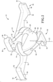
- the tie system 10 includes a first structural member 12 comprising a first hub 14 and a pair of first extension members 16 coupled to said first hub 14, such that the first extension members 16 extend outwardly from the first hub 14 in generally opposite directions.
- the tie system 10 further includes a second structural member 18 comprising a second hub 20 and a pair of second extension members 22 coupled to the second hub 20, such that the second extension members 22 extend outwardly from the second hub 20 in generally opposite directions.
- the first and second hubs 14, 20 are configured to be rotatably coupled to one other (when coupled together the hubs 14, 20 may define a hub portion) in a manner that permits rotation of the first and second structural members 12, 18 relative to one another about an axis of rotation 23 (See FIGS. 1-2 ) extending through the first and second hubs 14, 20.
- the hub 14 of the first structural member 12 is equipped with a hub projection 24, and the hub 20 of the second structural member 18 is equipped with a hub recess 26.
- the hub projection 24 is received within the hub recess 26 so as to rotatably couple the first and second structural members 12, 18 together.
- Such a configuration provides for the tie system 10 to be capable of shifting between a collapsed configuration and an expanded configuration (as will be discussed in more detail below) by rotating the first and second structural members 12, 18 relative to one another about the axis of rotation 23.
- the tie system 10, as described above, is further operable to be configured in an assembled and disassembled configuration.
- FIGS. 1-3 the tie system 10 is shown in the assembled configuration, where the first and second structural members 12, 18 are rotatably coupled to one another in a scissor-like configuration.
- the first and second structural members 12, 18 can rotate relative to one another on an axis of rotation that extends through the coupled first and second hubs 14, 20. This manner of rotatably coupling the first and second structural members 12, 18 gives the tie system 10 the scissor-like configuration.
- the term "scissor-like configuration" means a configuration of two elongated components, where the elongated components are rotatably coupled to one another at a connection location that is spaced from ends of both the elongated components, so that expansion or contraction of the ends of the components on one side of the connection location causes corresponding expansion or contraction of the ends of the components on the other side of the connection location.
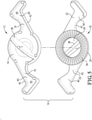
- FIGS. 4-6 show the tie system 10 in a disassembled configuration, where the first and second structural members 12, 18 are not coupled to one another.
- first and second structural members 12, 18 may each have substantially the same shape. Furthermore, each of the first and second structural members 12, 18 may be substantially symmetrical about the axis of rotation 23. In some embodiments, the first and second structural members 12, 18 may each have a length of between 3 to 18 inches, between 4 to 15 inches, between 5 to 12 inches, or between 6 to 9 inches. Additionally, in some embodiments, the first and second structural members 12, 18 may each have a width of between 1 to 6 inches, between 2 to 5 inches, or between 3 to 4 inches. Finally, in some embodiments the hubs 14, 20 will have a width (e.g., an outer diameter) of between 1 to 12 inches, between 2 to 6 inches, between 2.5 to 4 inches, or between 2.75 to 3.25 inches, one inch corresponding to 2.54 cm.
- a width e.g., an outer diameter
- each of the first and second structural members 12, 18 of the tie system 10 presents an inwardly-facing side 30 and an outwardly-facing side 32, with the inwardly and outwardly-facing sides 30, 32 of each structural member 12, 18 facing an opposite direction.
- the inwardly-facing sides 30 of the first and second structural members 12, 18 engage one another.
- the hub 14 of the first structural member 12 may be formed with the hub projection 24 and the hub 20 of the second structural member 18 may be formed with the hub recess 26.
- the hub projection 24 may extend from a portion of the inwardly-facing side 30 of the first structural member 12.
- the hub projection 24 may form at least a portion of the inwardly-facing side 30 of the first structural member 12.
- the hub recess 26 penetrates within the second hub 20 from the inwardly-facing side 30 of the second structural member 18.
- the hub recess 26 extends through an entire width of the second hub 20, such that the hub recess 26 presents an opening through the second hub 20.
- Embodiments provide for the hub projection 24 and the hub recess 26 to be complementary sized, such that the hub projection 24 can be received within the hub recess 26 in the assembled configuration, such as shown in FIGS. 1-3 .
- the hub projection 24 has a cross-sectional area of 0.1, 0.25, 0.5, 0.75, 1, or more square inches.
- the hub recess 26 may present a cross-sectional open area of at least 0.1, 0.25, 0.5, 0.75, 1, or more square inches.
- the tie system 10 can be assembled by inserting the hub projection 24 into the hub recess 26. In such an assembled configuration, the receipt of the hub projection 24 in the hub recess 26 inhibits translation of the first and second structural members 12, 18, while permitting rotation of the first and second structural members 12, 18 relative to one another on the axis of rotation 23.
- each of the first and second structural members 12, 18 further provide for each of the first and second structural members 12, 18 to include a plurality of radially-extending ribs 34 extending about at least a portion of the inwardly-facing sides 30 of the members' hubs 14, 20.
- each of the ribs 34 is separated by a gap 36.
- the ribs 34 of the first structural member 12 are configured to engage within the gaps 36 of the second structural member 18, and the ribs 34 of the second structural member 18 are configured to engage within the gaps 36 of the first structural member 12.
- the ribs 34 and gaps 36 are configured engage with each other so as to hold the first and second structural members 12, 18 relative to one another in a plurality of different rotational positions.
- the first and second structural members 12, 18 may be "locked” in various relative rotational positions.
- Such a configuration provides for a single tie system 10 to be used with insulation layers of varying sizes (e.g., varying thicknesses). It is understood that a greater number of ribs 34 facilitates the first and second structural members 12, 18 to be held in a correspondingly greater number of different rotational positions.
- Certain embodiments may provide for each of the first and second structural members 12, 18 to include between 10 and 200 ribs 34, between 20 and 100 ribs 34, or between 40 and 60 ribs 34.
- certain embodiments will provide for the first and second structural members 12, 18 to be held in a plurality of different rotational positions via positioning nubs and corresponding positioning notches.
- each of the first and second hubs 14, 20 includes a barrier 38 extending generally perpendicularly from a portion of the hubs' outwardly-facing sides 32.
- the barriers 38 may present a rounded outer profile that forms at least a portion of the outwardly-facing sides 32.
- the barriers 38 may each comprise a substantially planar member having two substantially flat sides. As such, the barriers 38 may each have the general shape of a half disk. In other embodiments, the barriers 38 may each have the general shape of a half sphere.
- the first and second extension members 16, 22 will each comprise a main sidewall 40 and a perimeter wall 42.
- the perimeter sidewalls 42 may extend away from the outwardly-facing sides 32 of their respective extension member 16, 22.
- the perimeter sidewalls 40 may be generally perpendicular to their respective main sidewall 40.
- the main sidewall 40 and perimeter sidewall 42 of each of the first and second extension members 16, 22 present an open void 44 bounded by the sidewalls 40, 42.
- first and second extension members 16, 22 each comprise an enlarged end portion 50, with the end portions 50 including oppositely facing heel portions 52 and toe portions 54.
- the end portions 50 will include an end wall 56 that extends from the inwardly-facing side 30 of the first and second extension members 16, 22.
- the end walls 56 of each of the first and second extension members 16, 22 are configured to facilitate receipt of concrete when portions of the first and second extension members 16, 22 are embedded in concrete (as discussed in more detail below), so as to prevent pullout of the tie system 10 from the concrete.
- each end portion 50 may further comprise a holding aperture extending through a thickness of the end portion 50. As such, the holding apertures may be configured to receive concrete when the end portions 50 are embedded in concrete, so as to prevent pullout of the tie system 10 from the concrete.
- FIG. 3 the tie system 10, as described above, is capable of being held in a plurality of different rotational positions.
- FIG. 3 illustrates the tie system 10 in an expanded configuration, i.e., with both the first and second structural members 12, 18 in solid-line.
- FIG. 3 also illustrates the tie system 10 in a partially-collapsed configuration, i.e., with the first structural member 12 in solid line and the second structural member 18 in dashed-line.
- the tie system 10 in a collapsed configuration, can be inserted into an opening formed in an insulation layer used in an insulated concrete panel. After the tie system 10 has been inserted in the opening of the insulation layer, the tie system can be transitioned to the expanded configuration where concrete can be poured about the tie system 10 and the insulation layer for manufacturing the insulated concrete panel.
- the first and second structural members 12, 18 of the tie system 10 can be supplied to an insulated concrete panel maker (e.g., a "pre-caster") in the disassembled configuration (i.e., with the first and second structural members 12, 18 decoupled from one another).
- a plurality of the tie systems 10 can used by the panel maker to rigidly connect two layers of concrete that have an insulation layer, such as an expanded or extruded polystyrene board, positioned between the concrete layers.
- insulation layers can be formed from expanded polystyrene, polyisocyanurate, expanded polyethylene, extruded polyethylene, or expanded polypropylene.
- the panel maker can select the unassembled first structural member 12 and the second structural member 18 and then connect them to one another, as previously described, by inserting the hub projection 24 of the first structural member 12 into the hub recess 26 of the second structural member 18.
- the tie system 10 can be prepared for insertion into a tie opening 60 that has been formed in an insulation layer 62 (e.g., a panel or a board) so as to manufacture an insulated concrete panel.
- the tie opening 60 may be substantially cylindrical and may be formed using a hand drill and a core bit. However, embodiments may provide for the tie opening 60 to have other shapes and to be formed from other methods.
- the tie system 10 Prior to insertion into the tie opening 60, the tie system 10 is shifted into a collapsed configuration, where a width Wc between adjacent end portions 50 of each of the first and second extensions members 16, 22 is minimized to be less than a width Wo of the tie opening 60 and/or less than a width of the hubs 14, 20 of the structural members 12, 18.
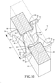
- FIGS. 8-9 when the tie system 10 is in the collapsed configuration, it can then be inserted into tie opening 60 of the insulation layer 62 until the hubs 14, 20 of the tie system are substantially centered in the tie opening 60.
- the tie system 10 can be shifted into the expanded configuration.
- a width We between the adjacent end portions 50 of each of the first and second extension members 16, 22 is maximized to be greater than the width Wo of the tie opening 60 (see FIG. 7 ) and/or greater than the width of the hubs 14, 20.
- a ratio of We to Wc of the tie system 10 is at least 1.2:1, 1.5:1, 2:1, or 3:1.
- a maximum width of the tie system 10 is less than a maximum width of the first and second hubs 14, 20 and the tie opening 60
- the maximum width of the tie system 10 is greater than the maximum width of the first and second hubs 14, 20 and the tie opening 60.
- the tie system 10 may be described as having first and second end sections 64, 66.
- the first end section 64 may comprise one of the end portions 50 of the first extension member 16 and the adjacent end portion 50 of the second extension member 22.
- the second end section 66 may comprise the other end portion 50 of the first extension member 16 and the adjacent end portion 50 of the second extension members 22.
- the width of the first and second end sections 64, 66 are defined as the width Wc when the tie system is in the collapsed configuration
- the width of the first and second end sections 64, 66 are defined as the width We when the tie system 10 is in the expanded position.
- maximum widths of the first and second end sections 64, 66 are each greater than the maximum width of the tie opening 60, and in the collapsed configuration, maximum widths of the first and second end sections 64, 66 are each less than the maximum width of the tie opening 60.
- the end portions 50 of the extension members 16, 22 engage the insulation layer 62 in four contact locations 68 located outside of, but proximate to, the tie opening 60. Two of these contact locations 68 are on one side of the insulation layer 62 and the other two of the contact locations 68 are on the opposite side of the insulation layer 62. As previously described, the end portions 50 of each extension member 16, 22 are enlarged relative intermediate portions of the extension members 16, 22. Such an enlargement provides for the heel 52 to engage a surface of the insulation layer 62 and the toe 54 to extend outwardly from the surface of the insulation layer 62.
- the rounded outer profiles of the barriers 38 of each of the hubs 14, 20 substantially conform to a cross-sectional shape of the tie opening 60.
- the hubs 14, 20, including the barriers 38 fill up a substantial portion of the cross-sectional area of the tie opening 60.
- Such filling up being due, in part, to the barriers 38 of the first and second hubs 14, 20 being more closely aligned with one another when the tie system 10 is in said expanded configuration (i.e., FIGS. 10-11 ) than when the tie system 10 is in said collapsed configuration (i.e., FIGS 8-9 ).
- the hubs 14, 20, including the barriers 38 fill at least 70%, 80%, 90%, or 100% of the cross-sectional area of the tie opening 60 when the tie system 10 is in the expanded configuration.
- the barriers 38 are configure to thermally isolate layers of concrete that will be placed on opposite sides of the insulation layer 62.
- the barriers 38, the hubs 14, 20, and/or the entire tie system 10 may be formed of, or coated with, a material having a thermal conductivity that is less than steel, preferably less than concrete.
- the barriers 38, the hubs 14, 20, and/or the entire tie system 10 may be formed of, or coated with, a material having a thermal conductivity less than 10, 5, 1, 0.5, or 0.1 W/(m.K).
- the barriers 38, the hubs 14, 20, and/or the entire tie system 10 may formed from a synthetic resin, such as an epoxy.
- the synthetic resin may include reinforcing fibers, such as glass fibers and/or carbon fibers.
- an insulated concrete panel 70 can be manufacture by pouring top and bottom concrete layers 72, 74 on opposite sides of the insulation layer 62.
- the insulated concrete panel can have a variety of sizes.
- tie systems 10 will be positioned throughout the insulated concrete panels approximately every 8 to 10 square feet ( FIG. 12 may not be drawn to scale, but is provided for illustration of an insulated concrete panel having a plurality tie systems 10 included therein). In some cases of high loading, the tie systems 10 will need to be positioned closer together.
- Typical insulated concrete panels can include between 10 to 100, between 20 to 80, or between 25 to 40 tie systems 10 within each insulated concrete panel.
- the tie systems 10 can be aligned along a longitudinal or transverse direction of the insulated concrete panel 70 or at any other angle as deemed necessary by an engineer.
- outer panels 76 such as facades may be positioned exterior of the top and bottom layers of concrete 72, 74.
- the bottom layer of concrete 74 is poured in a concrete form.
- the insulation layer 62 with tie systems 10 coupled thereto can be lowered into engagement with the bottom layer of concrete 74.
- the end portions 50 of the tie systems 10 that extend down from a bottom surface of the insulation layer 62 become inserted into and embedded in the bottom layer of concrete 74.
- the bottom surface of the insulation layer 62 may be inserted within at least a top surface of the bottom layer of concrete 74.
- Reinforcement in the form of rebar, steel mesh, or prestress strand may also be inserted into the bottom layer of concrete 74.
- the tie systems 10 may need to be turned in the tie opening 60 or even relocated a few inches away, so as to avoid contact with any such reinforcements.
- the tie system 10 may be flexible enough to accommodate such turning and/or relocation.
- the top layer of concrete 72 can be poured on a top surface of the insulation layer 62.
- the end portions 50 of the tie systems 10 that extend up from the top surface of the insulation layer 62 become embedded in the top layer of concrete 72.
- the barriers 38 of the tie systems 10 inhibit passage of concrete from the top layer 72 entirely through the tie opening 60 in the insulation layer 62 and into contact with the bottom layer of concrete 74. As such, a continuous air void can be maintained in the tie opening 60, above the bottom layer of concrete 74 and below the barriers 38.
- At least a portion of the tie opening 60 will be filled with concrete from the first and/or second layers of concrete 72, 74. Nevertheless, embodiments provide for at least 10%, 20%, 30%, or 40% of a volume of the tie opening 60 to be filled with the air void. Such an air void improves thermal isolation between the top and bottom layers of concrete 72, 74, even with such top and bottom layers 72, 74 being indirectly connected via the tie systems 10.
- embodiments of the present invention include an insulated concrete panel 70 comprising: an insulation layer 62 with a tie opening 60 extending therethrough, first and second concrete layers 72, 74 disposed on generally opposite sides of the insulation layer 62, and at least one tie system 10 interconnecting the concrete layers.
- the tie system 10 may comprise: hubs 14, 20 (collectively, a "hub portion") at least partly receive in the tie opening 60 of the insulation layer 62, a first end section 64 at least partly embedded in the first concrete layer 72, and a second end section 66 at least partly embedded in the second concrete layer 74, with the tie system 10 being capable of shifting from a collapsed configuration, in which a maximum width Wc of the first and second end sections 64, 66 is less than a maximum width Wo of the tie opening 60, to an expanded configuration, in which the maximum width We of the first and second end sections 64, 66 is greater than the maximum width Wo of the tie opening 60.
- embodiments of the present invention include a method 1300 of making an insulated concrete panel.
- the method 1300 includes the initial Step 1302 of creating a tie opening that extends through an insulation layer.
- a next Step 1304 includes inserting an expandable tie system into the tie opening.
- Step 1306 while the tie system is received in the tie opening and with opposite ends of the tie system extending out of the tie opening, shifting the tie system into an expanded configuration where a maximum width of the tie system is greater than a maximum width of the tie opening.
- a layer of concrete is formed on each side of the insulation layer so that opposite end portions of the tie system are embedded in the opposite layers of concrete, thereby physically coupling the layers of concrete to one another using the tie system.
- the tie systems 10 are formed so as to present an "X" shape with an intersection of the X-shape being located at the hubs 14, 20.
- the "X" shape of the tie systems 10 allows for the tie systems 10 to effectively transfer shear forces between the layers of concrete 72, 74 without deforming the insulation layer 62 therebetween.
- the resulting insulated concrete panel 70 is configured as a composite panel.
- the tie system 10 is also configured to act as a tension member that will prevent the top and bottom layers of concrete 72, 74 from delamination during lifting and shipping.
- the insulated concrete panel 70 can be reinforced with rebar, steel mesh, post tension cables, clergyess strand, or a combination of reinforcement as needed by the particular job requirements so as to further reinforce the insulated concrete panel 70.
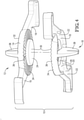
- Embodiments of the present invention provide for an additional embodiment of a tie system, which is illustrated as tie system 80 in FIGS. 14-15 .
- the additional tie system 80 functions in substantially the same manner as the tie system 10 depicted in FIGS. 1-13 ; however, each structural member 12, 18 of the additional tie system 80 is formed from more than one material.
- a material of construction of each of the tie system's 80 hubs 14, 20 is different that a material of construction of each of the extension members 16, 22.
- the extension members 16, 22 may be separable from the hubs 14, 20, respectively.
- each of the extension members 16, 22 may include a base 82 comprising extension connection elements 84.
- such connection elements 84 of the extension members 16, 22 will further include protrusions 88 (See FIG. 15 ).
- each of the hubs 14, 20 may include connection elements 86.
- Such connection elements 86 of the hubs 14, 20 may be formed with cavities 90 (See FIG. 14 ).
- the protrusions 88 may be configured to be received within the cavities 90, such that the extension members 16, 22 can be removable secured to the hubs 14, 20.
- each of the extension members 16, 22 can be formed of a material of high thermal conductivity (e.g., steel), while each of the hubs 14, 20 can be formed of a material of low thermal conductivity (e.g., a synthetic resin or fiber-reinforced composite material).
- a material of high thermal conductivity e.g., steel
- each of the hubs 14, 20 can be formed of a material of low thermal conductivity (e.g., a synthetic resin or fiber-reinforced composite material).
- a material of low thermal conductivity e.g., a synthetic resin or fiber-reinforced composite material.
- the high strength material e.g., steel
- the tie systems 80 will provide for the tie systems 80 to have a tensile strength of at least 10,000 psi.
- the insulating material used for the hubs 14, 20 may include a synthetic resin, such as an epoxy.
- a ratio of the thermal conductivity of the material used in the extension members 16, 22 to the material used for the hubs 14, 20 can be at least 2:1, at least 5:1, at least 10:1, or at least 50:1.
- the thermal conductivity of the extension members 16, 22 can be at least 1, at least 5, at least 10, or at least 20 W/(m.K), while the thermal conductivity of the hubs 14, 20 can be less than 5, less than 2, less than 1, less than 0.5, or less than 0.1 W/(m.K).
- the inwardly-facing side 30 of the first structural member 12 can include one or more positioning nubs 92 (See FIG. 14 ), while the inwardly facing side 30 of the second structural member 18 can be configured with a plurality of spaced-apart positioning notches 94 (See FIG. 15 ).
- the positioning notches 94 are sized and located to receive the positioning nubs 92 as the first and second structural members 12, 18 are rotated relative to one another. When the positioning nubs 92 are received in the positioning notches 94, relative rotation of the first and second structure members 12, 18 is inhibited.
- the additional tie system 80 can be used with insulation layers of varying thickness.
- the extension members 16, 22 are manufactured first and then placed in a mold for connection with the hubs 14, 20 while the hubs 14, 20 are being manufactured. In this manner, the hubs 14, 20 can be formed around connection elements 84 at the base 82 of each extension member 16, 22 to ensure a strong and secure connection between the extension members 16, 22 and the hubs 14, 20.
- the hubs 14, 20 are formed of a synthetic resin material
- the extension members 16, 22 can be coupled to the hubs 14, 20 by first inserting the bases 82 of the extension members 16, 22 into a mold (e.g., an injection molding form) and then introducing the synthetic into the form so that the resin surrounds the connection elements 84 at the base 82 of the extension members 16, 22.
- the reinforcing fibers can be placed in the mold before and/or during addition of the synthetic resin.
- the extension members 16, 22 and hubs 14, 20 can be separately manufactured and then later attached to one another via any know fastening mechanisms such as, for example, screws, bolts, press-fitting, etc.
- each of the four extension members 16, 22 that make up the additional tie system 80 can have an identical configuration, thereby reducing manufacturing costs. Additionally, each of the two hubs 14, 20 of the additional tie system 80 can initially be manufactured with an identical configuration and then later modified to mate with one other. For example, both hubs 14, 20 of the additional tie system 80 can be being identically manufactured with the hub recess 26 and no hub projection 24.
- both hubs 14, 20 are identically manufactured with a hub recess 26
- a separately manufactured hub projection 24 can be inserted (e.g., press-fit) into one of the hub recesses 26 after initial manufacturing of the hubs 14, 20, thus allowing one of the hubs 14, 20 to be provided with a hub projection 24 that can be matingly received in the hub recess 26 of the other hub 14, 20.
- the extension members can be formed of a metallic material, such as steel.
- the extension members may be formed by cutting an initial flat elongated member from a large sheet and then bending the flat member into the final shape of an extension member (e.g., 16 or 22). Such cutting may include stamping the elongated flat member out of the metallic sheet. The bending forms the perimeter sidewalls 42 at the outer perimeter of the extension members (e.g., 16 or 22) and also forms the connection elements 84 at the base 82 of the extension members (e.g. 16, 22). As such, the two extension members (e.g., 16 or 22) can be rigidly connected via a hub (e.g., 14 or 20).
- a hub e.g., 14 or 20
- the hub (e.g., 14 or 20) can be formed around the base 82 of the extension members (e.g., 16 or 22) so that said base 82 of each of the extension members (e.g., 16 or 22) is at least partly embedded in the hub (e.g., 14 or 20).
- the base 82 of each of the extension members (e.g., 16 or 22) may be placed in a hub form and thereafter the hub form may be filled with a synthetic resin to thereby form the hub (e.g., 14 or 20).
- the synthetic resin may include an epoxy.
- reinforcing fibers e.g., glass fibers and/or carbon fibers
- the hub e.g., 16 or 22
- the hub includes a hub recess 26.
- a hub projection 24 is inserted into the hub recess 26 and attached to the hub recess 26 via press-fitting.
- the previously-described bending of the flat members forms the perimeter sidewalls 42 which may be bent substantially perpendicular to the main sidewall 40 of the extension members (e.g., 16 or 22). As such, an open void 44 is defined within the perimeter sidewalls 42 of the extension members (e.g., 16 or 22).
- the bending further forms the connection elements 84 at the base 82 of the extension members (e.g., 16, 22), with such connection elements 84 being used to secure the extension members (e.g., 16, 22) to the hub (e.g., 14 or 20), as previously described.
- the multi-material tie system shown in FIGS. 14-15 can be used to form an insulated concrete panel 70 in the same manner as describe above with respect to the single-material tie system shown in FIGS. 1-13 .
- a description of how the multi-material tie system is positioned into the insulation layer 62 and then used to connect top and bottom concrete layers 72, 74 on each side of the insulation layer 62 is the same as described above for tie system 10.
Landscapes
- Engineering & Computer Science (AREA)
- Architecture (AREA)
- Civil Engineering (AREA)
- Structural Engineering (AREA)
- Building Environments (AREA)
Claims (9)
- Chaînage (10) destiné à être utilisé avec des panneaux de béton isolés, les panneaux étant formés d'une ou de plusieurs couches isolantes prises en sandwich entre des couches de béton, le chaînage (10) comprenant :un premier élément structurel (12) comprenant un premier moyeu (14) et une paire de premiers éléments d'extension (16) accouplés audit premier moyeu (14) de telle sorte que les premiers éléments d'extension (16) s'étendent vers l'extérieur depuis le premier moyeu (14) dans des directions généralement opposées ;un second élément structurel (18) comprenant un second moyeu (20) et une paire de seconds éléments d'extension (22) accouplés au second moyeu (20), de telle sorte que les seconds éléments d'extension (22) s'étendent vers l'extérieur depuis le second moyeu (20) dans des directions généralement opposées ;caractérisé en ce quelesdits premier et second éléments structurels (12, 18) sont orientés dans une configuration sensiblement en forme de X avec une intersection de la forme en X étant située au niveau des premier et second moyeux (14, 20), de sorte que les forces de cisaillement sont transférées entre lesdites couches de béton (72, 74) sans déformer la couche isolante (62) entre elles,dans lequel lesdits premier et second moyeux (14, 20) sont conçus pour être accouplés en rotation l'un à l'autre d'une manière qui permet la rotation desdits premier et second moyeux (14, 20) l'un par rapport à l'autre sur un axe de rotation s'étendant à travers lesdits premier et second moyeux (14, 20) ;dans lequel lorsque lesdits premier et second moyeux (14, 20) sont accouplés en rotation l'un à l'autre, le chaînage peut être déplacé entre une configuration repliée et une configuration déployée en faisant tourner lesdits premier et second éléments structurels (12, 18) l'un par rapport à l'autre sur ledit axe de rotation ;dans lequel l'un desdits premier et second moyeux (14, 20) présente une saillie de moyeu (24) et l'autre desdits premier et second moyeux (14, 20) présente un évidement de moyeu (26) dans lequel ladite saillie de moyeu (24) est reçue dans ledit évidement de moyeu (26) de manière à accoupler de manière rotative les premier et second éléments structurels (12, 18).
- Chaînage (10) selon la revendication 1, dans lequel lesdits premier et second éléments structurels (12, 18) sont accouplés de manière rotative l'un à l'autre dans une configuration de type ciseaux.
- Chaînage (10) selon la revendication 1 ou la revendication 2, dans lequel chacun desdits moyeux (14, 20) comporte une barrière s'étendant vers l'extérieur (38), dans lequel chacune desdites barrières (38) a la forme d'une demi-sphère.
- Chaînage (10) selon l'une quelconque des revendications 1 à 3, dans lequel les parties d'extrémité agrandies (50) des premier et second éléments d'extension (16, 22) comportent des parties de talon (52) et des parties d'orteil (54) opposées.
- Chaînage (10) selon l'une quelconque des revendications 1 à 4, dans lequel ledit chaînage (10) est formé d'une résine synthétique renforcée de fibres ayant une conductivité thermique inférieure à 0,5 watts par mètre Kelvin
- Panneau de béton isolé (70), ledit panneau comprenant :une couche isolante (62) ayant une ou plusieurs ouvertures (60) s'étendant à travers elle ;une première couche de béton (72) adjacente à une première surface de ladite couche isolante (62) ;une seconde couche de béton (74) adjacente à une seconde surface de ladite couche isolante qui est généralement opposée à la première surface de ladite couche isolante (62) ; etun chaînage (10) selon l'une quelconque des revendications précédentes reçu dans l'une desdites ouvertures (60) dans ladite couche isolante (62).
- Panneau (70) selon la revendication 6, dans lequel les premier et second éléments d'extension (16, 22) comprennent chacun une partie d'extrémité agrandie ((50), qui comporte une partie de talon (52) et une partie d'orteil (54) orientées de manière opposée ainsi qu'une paroi d'extrémité (56) s'étendant depuis le côté tourné vers l'intérieur de chacun des premier et second éléments d'extension (16, 22), dans lequel les parois d'extrémité (56) sont conçues pour faciliter la réception de béton lorsque des parties des premier et second éléments d'extension (16, 22) sont noyés dans le béton de manière à empêcher l'arrachement du chaînage (10).
- Panneau (70) selon la revendication 6 ou la revendication 7, dans lequel ladite une desdites ouvertures (60) dans ladite couche isolante (62) est sensiblement cylindrique, dans lequel les moyeux (14, 20) comportant des barrières (38) remplissent au moins 90 % de la section transversale de ladite une desdites ouvertures (60) dans ladite couche isolante (62).
- Panneau (70) selon l'une quelconque des revendications 6 à 8, dans lequel des parties d'extrémité agrandies (50) des premier et second éléments d'extension (16, 22) mettent en prise la couche isolante (62) à deux emplacements sur la première surface de la couche isolante (62) et à deux emplacements sur la seconde surface de la couche d'isolation (62), lesdits emplacements étant situés à l'extérieur de, mais à proximité de, l'ouverture d'attache (60).
Applications Claiming Priority (3)
| Application Number | Priority Date | Filing Date | Title |
|---|---|---|---|
| US201361915675P | 2013-12-13 | 2013-12-13 | |
| US14/265,931 US9103119B2 (en) | 2013-12-13 | 2014-04-30 | Tie system for insulated concrete panels |
| PCT/US2014/067427 WO2015088777A1 (fr) | 2013-12-13 | 2014-11-25 | Système de chaînage pour panneaux de béton isolés |
Publications (3)
| Publication Number | Publication Date |
|---|---|
| EP3068962A1 EP3068962A1 (fr) | 2016-09-21 |
| EP3068962A4 EP3068962A4 (fr) | 2017-11-15 |
| EP3068962B1 true EP3068962B1 (fr) | 2022-02-09 |
Family
ID=53367751
Family Applications (1)
| Application Number | Title | Priority Date | Filing Date |
|---|---|---|---|
| EP14869437.5A Active EP3068962B1 (fr) | 2013-12-13 | 2014-11-25 | Système de chaînage pour panneaux de béton isolés |
Country Status (6)
| Country | Link |
|---|---|
| US (1) | US9103119B2 (fr) |
| EP (1) | EP3068962B1 (fr) |
| CN (1) | CN105940166B (fr) |
| AU (1) | AU2014364324B2 (fr) |
| CA (2) | CA3060640C (fr) |
| WO (1) | WO2015088777A1 (fr) |
Families Citing this family (6)
| Publication number | Priority date | Publication date | Assignee | Title |
|---|---|---|---|---|
| US9957713B2 (en) | 2011-05-11 | 2018-05-01 | Composite Technologies Corporation | Load transfer device |
| US9493946B2 (en) * | 2013-12-13 | 2016-11-15 | Iconx, Llc | Tie system for insulated concrete panels |
| US9303404B2 (en) * | 2014-07-09 | 2016-04-05 | Lehigh University | Insulated structural panel connector |
| WO2018128613A1 (fr) * | 2017-01-05 | 2018-07-12 | Composite Technologies Corporation | Dispositif de transfert de charge |
| US11452267B2 (en) * | 2020-08-04 | 2022-09-27 | Gabriel Pena | Plant training device |
| US12091855B1 (en) * | 2020-11-10 | 2024-09-17 | Jason McSpadden Woodland | Insulated tilt-up wall panel |
Family Cites Families (91)
| Publication number | Priority date | Publication date | Assignee | Title |
|---|---|---|---|---|
| US1053231A (en) * | 1908-06-08 | 1913-02-18 | William Schweikert | Building structure. |
| US1088290A (en) * | 1913-04-09 | 1914-02-24 | Archie T Mcallister | Hanger for concrete work. |
| US1302727A (en) * | 1917-03-12 | 1919-05-06 | Avila O Thomas | Wall-bond. |
| US1503148A (en) * | 1922-05-03 | 1924-07-29 | Bernstrom Harry William | Combined reenforce and leveler |
| US1700889A (en) * | 1924-06-06 | 1929-02-05 | John N Heltzel | Collapsible form |
| US1801273A (en) * | 1930-03-22 | 1931-04-21 | Himmel Brothers Company | Corner clamp for store-front construction |
| US1975156A (en) * | 1931-03-28 | 1934-10-02 | Herbert M Knight | Building |
| US2178782A (en) * | 1938-11-10 | 1939-11-07 | Plibrico Jointless Firebrick C | Wall support |
| US2400670A (en) * | 1945-05-03 | 1946-05-21 | May William Vander | Wall tie |
| US2412253A (en) * | 1945-12-17 | 1946-12-10 | Higgins Ind Inc | Wall panel |
| US2765139A (en) * | 1953-12-29 | 1956-10-02 | White Claude | Beam clamp |
| US2923146A (en) * | 1955-03-31 | 1960-02-02 | Adjustable Anchor Corp | Adjustable anchor for fixtures |
| US3018080A (en) * | 1959-03-18 | 1962-01-23 | Minerallac Electric Company | Scissor-clip |
| US3296763A (en) * | 1964-07-28 | 1967-01-10 | Al Lipson | Devices for removably locking panels in framing |
| US3357287A (en) * | 1966-06-02 | 1967-12-12 | Wiss And Sons Co J | Latching means for tools having pivoted members |
| CA932971A (en) * | 1971-07-06 | 1973-09-04 | Spiroll Corporation Ltd. | Method of panel connection and connectors therefor |
| US3715850A (en) * | 1971-08-25 | 1973-02-13 | J Chambers | Adjustable mounting device |
| US4037978A (en) * | 1974-08-23 | 1977-07-26 | B.C. Investments Ltd. | Resilient swivel connector |
| US3925595A (en) * | 1975-02-24 | 1975-12-09 | Aluminum Co Of America | Frameless damping spacer |
| US3940553A (en) * | 1975-02-24 | 1976-02-24 | Aluminum Company Of America | Frameless spacer with viscoelastic damping means |
| US4027988A (en) * | 1975-10-28 | 1977-06-07 | Dong Woo Kum | Joint connector for bars |
| DE2557846A1 (de) * | 1975-12-22 | 1977-06-30 | Hilti Ag | Befestigungselement fuer feuerfeste auskleidungen |
| US4059931A (en) * | 1976-01-29 | 1977-11-29 | Mongan William T | Building framing system for post-tensioned modular building structures |
| GB1549362A (en) * | 1976-03-30 | 1979-08-08 | Haeussler E | Multi-layer reinforced concrete slabs |
| US4194851A (en) * | 1977-11-10 | 1980-03-25 | Polyproducts Corp. | Universal hub for geodesic domes |
| US4157226A (en) * | 1978-03-27 | 1979-06-05 | Eric Reiter | Shaft connectors |
| DE3011362A1 (de) * | 1979-03-26 | 1980-10-16 | Gkn Reinforcements Ltd | Stuetzeinrichtung fuer eine betonbewehrung |
| US4223176A (en) * | 1979-05-17 | 1980-09-16 | Aluminum Company Of America | Damping spacer with hub interlock and method of making |
| US4393635A (en) | 1981-04-30 | 1983-07-19 | Long Robert T | Insulated wall construction apparatus |
| US4471156A (en) * | 1983-01-27 | 1984-09-11 | Aluminum Company Of America | Damping spacer with variable damping feature |
| US4723388A (en) * | 1985-04-26 | 1988-02-09 | Mansion Industries, Inc. | Easily formable grid for windows and the like |
| US4637748A (en) * | 1985-06-07 | 1987-01-20 | T. A. Pelsue Company | Hub and strut-endcap assembly for tent frame struts |
| US4765109A (en) * | 1987-09-25 | 1988-08-23 | Boeshart Patrick E | Adjustable tie |
| ATE85380T1 (de) * | 1987-10-14 | 1993-02-15 | Kanya Ag | Baukastensystem mit knoten- und stabelementen. |
| US5371991A (en) * | 1987-12-07 | 1994-12-13 | Bechtel; Richard | Re-bar clamp assembly |
| US4904108A (en) * | 1988-03-28 | 1990-02-27 | Wendel Wendel R | Geo hub |
| US4852324A (en) * | 1988-12-01 | 1989-08-01 | Conoco Inc. | Variable angle refractory anchor for connecting surfaces |
| US5154034A (en) * | 1991-01-11 | 1992-10-13 | Stanek Ronald F | Muntin bar stabilizer with pad and method of stabilizing |
| US5252017A (en) * | 1991-01-30 | 1993-10-12 | Wedgerock Corporation | Setback retaining wall and concrete block and offset pin therefor |
| US5272850A (en) * | 1991-05-06 | 1993-12-28 | Icon, Incorporated | Panel connector |
| US5302039A (en) * | 1992-08-11 | 1994-04-12 | Omholt Bruce D | Panel coupler |
| US5456048A (en) * | 1993-12-13 | 1995-10-10 | Caradon Better-Bilt, Inc. | Muntin clip |
| US5564658A (en) * | 1993-12-29 | 1996-10-15 | B-Line Systems, Inc. | Support system for data transmission lines |
| US5673525A (en) * | 1994-04-08 | 1997-10-07 | H.K. Composites, Inc. | Insulating connector rods used in making highly insulated composite wall structures |
| US5570552A (en) * | 1995-02-03 | 1996-11-05 | Nehring Alexander T | Universal wall forming system |
| US5517794A (en) * | 1995-03-10 | 1996-05-21 | James Michael Wagner | Apparatus for forming vinyl siding corners extending over walls intersecting at obtuse angles |
| US6202375B1 (en) | 1997-10-28 | 2001-03-20 | Rolf Otto Kleinschmidt | Method for concrete building system using composite panels with highly insulative plastic connector |
| CA2316238C (fr) * | 1997-12-24 | 2006-06-13 | Delta-Tie, Inc. | Connecteur de tirants structuraux pour parois sandwich isolantes en beton |
| US5899033A (en) * | 1998-01-30 | 1999-05-04 | Lake Country Sales, Inc. | Adjustable hub assembly for window muntins |
| DE19809617C2 (de) * | 1998-03-06 | 2000-05-25 | Brueder Eckelt & Co Glastech | Befestigungseinrichtung für Platten, insbesondere für Glasplatten |
| US6088985A (en) | 1998-12-24 | 2000-07-18 | Delta-Tie, Inc. | Structural tie shear connector for concrete and insulation sandwich walls |
| DE19945196C2 (de) * | 1999-09-21 | 2001-09-20 | Dorma Gmbh & Co Kg | Befestigungsvorrichtung für eine Glasscheibe |
| DE19945197C1 (de) * | 1999-09-21 | 2001-07-05 | Dorma Gmbh & Co Kg | Befestigungsvorrichtung für eine Glasscheibe |
| US6606786B2 (en) * | 1999-11-15 | 2003-08-19 | Peter G. Mangone, Jr. | Device for forming an enclosure |
| US6298549B1 (en) * | 1999-11-15 | 2001-10-09 | Peter G. Mangone, Jr. | Apparatus and device for forming an enclosure |
| DE10009531A1 (de) * | 2000-02-29 | 2001-08-30 | Fischer Artur Werke Gmbh | Halterung zur Befestigung von plattenförmigem Material an einer Unterkonstruktion |
| EP1294999B1 (fr) * | 2000-06-08 | 2009-10-14 | PATEA GmbH | Assemblage du type a ciseaux avec corps d'assemblage pour le support de toit d'une tente pliante |
| US6675546B2 (en) * | 2000-10-20 | 2004-01-13 | Total Structures, Inc. | Universal connector |
| US8484916B2 (en) * | 2001-03-22 | 2013-07-16 | F. Aziz Farag | Panel-sealing and securing system |
| US6705583B2 (en) * | 2001-10-05 | 2004-03-16 | Robert Daniels | Apparatus for building foundation stem wall forms |
| DE10162054C2 (de) * | 2001-12-17 | 2003-11-27 | Dorma Gmbh & Co Kg | Verbindungselement für eine gläserne Stützen-Riegel-Konstruktion |
| US6761007B2 (en) | 2002-05-08 | 2004-07-13 | Dayton Superior Corporation | Structural tie shear connector for concrete and insulation composite panels |
| US6817156B2 (en) * | 2002-09-03 | 2004-11-16 | Chiu Pang Mok | Device for positioning cast-in U-channels in concrete structure |
| US6895720B2 (en) * | 2002-09-25 | 2005-05-24 | Hk Marketing Lc | High strength composite wall connectors having tapered or pointed ends |
| US6915613B2 (en) * | 2002-12-02 | 2005-07-12 | Cellox Llc | Collapsible concrete forms |
| US6860454B1 (en) * | 2003-01-17 | 2005-03-01 | Yazaki North America, Inc. | Size adjustable clip for flexible flat cables |
| CN2695521Y (zh) * | 2003-12-10 | 2005-04-27 | 何正坤 | 一种防火轻质复合墙体 |
| US20050126014A1 (en) * | 2003-12-11 | 2005-06-16 | Mohammed Yamin | Cutting device with integral spring and lock screw |
| US7241071B2 (en) * | 2004-03-08 | 2007-07-10 | Jiffy Clip, Inc. | Swiveling multi-clamp fastener |
| CN2737855Y (zh) * | 2004-04-29 | 2005-11-02 | 珠海市晶艺玻璃工程有限公司 | 玻璃幕墙及屋面转盘连接件 |
| CN2771356Y (zh) * | 2005-03-21 | 2006-04-12 | 栾惠甥 | 一种保温砌块 |
| ITTO20050393A1 (it) * | 2005-06-09 | 2006-12-10 | Pontarolo Engineering Spa | Cassero a perdere per murature isolate in cemento armato. |
| CA2558403A1 (fr) * | 2005-09-06 | 2007-03-06 | Rocvale Produits De Beton Inc. | Raccord de blocs |
| US20070199254A1 (en) * | 2006-02-28 | 2007-08-30 | Frano Luburic | Nestable structural hollow body and related methods |
| US20090301025A1 (en) * | 2007-02-05 | 2009-12-10 | Kodi Klip Corporation | Telescoping Chair For Supporting Bars |
| US20080240846A1 (en) * | 2007-03-28 | 2008-10-02 | Phillips William J R E | Fence panel mounting system |
| US8215075B2 (en) * | 2008-03-18 | 2012-07-10 | Awi Licensing Company | Up-tight surface covering and attachment system |
| DE102008016572B4 (de) * | 2008-04-01 | 2011-07-28 | ITW Automotive Products GmbH & Co. KG, 58636 | Verbindungselement |
| US8112963B2 (en) * | 2008-06-25 | 2012-02-14 | Johnson Aubren M | Decorative accessory |
| DE102008041125A1 (de) * | 2008-08-08 | 2010-02-11 | Robert Bosch Gmbh | Halterung für ein Kraftfahrzeug-Anbauteil sowie Vorrichtung zum Halten eines Kraftfahrzeug-Anbauteils |
| US20100043337A1 (en) * | 2008-08-21 | 2010-02-25 | Stike Tool, Inc. | Spacer for concrete reinforcement wire |
| DE102008048425A1 (de) * | 2008-09-23 | 2010-04-01 | B.T. Innovation Gmbh | Abstandhalter |
| FR2939815B1 (fr) * | 2008-12-15 | 2012-03-09 | Gianfranco Ciccarelli | Bloc a bancher pour la construction de mur |
| US8312683B2 (en) | 2009-09-15 | 2012-11-20 | Tadros Maher K | Method for constructing precast sandwich panels |
| EP3388007A3 (fr) * | 2010-10-12 | 2019-02-20 | Zimmer, Inc. | Agencement de pince de fixation externe à verrou unique |
| GB201020152D0 (en) * | 2010-11-29 | 2011-01-12 | Airbus Uk Ltd | Aircraft panel structure and aircraft panel structure manufacturing method for alleviation of stress |
| ES2546178T3 (es) * | 2011-02-11 | 2015-09-21 | Orthofix S.R.L. | Abrazadera para fijación ortopédica externa, temporal o definitiva, y sistema de fijación externo que comprende dicha abrazadera |
| CA2776632C (fr) * | 2011-05-11 | 2019-08-13 | Composite Technologies Corporation | Dispositif de transfert de charge |
| US8555584B2 (en) | 2011-09-28 | 2013-10-15 | Romeo Ilarian Ciuperca | Precast concrete structures, precast tilt-up concrete structures and methods of making same |
| US8720156B2 (en) * | 2012-09-14 | 2014-05-13 | Charles Porter | Wall panel attachment system |
| CN203008210U (zh) * | 2012-12-11 | 2013-06-19 | 上海运尔实业有限公司 | 夹芯自保温砌块 |
-
2014
- 2014-04-30 US US14/265,931 patent/US9103119B2/en active Active
- 2014-11-25 AU AU2014364324A patent/AU2014364324B2/en not_active Ceased
- 2014-11-25 WO PCT/US2014/067427 patent/WO2015088777A1/fr not_active Ceased
- 2014-11-25 CN CN201480067897.8A patent/CN105940166B/zh active Active
- 2014-11-25 CA CA3060640A patent/CA3060640C/fr active Active
- 2014-11-25 EP EP14869437.5A patent/EP3068962B1/fr active Active
- 2014-11-25 CA CA2933332A patent/CA2933332C/fr active Active
Also Published As
| Publication number | Publication date |
|---|---|
| EP3068962A1 (fr) | 2016-09-21 |
| AU2014364324B2 (en) | 2018-08-09 |
| AU2014364324A1 (en) | 2016-06-23 |
| CN105940166B (zh) | 2019-03-29 |
| US20150167303A1 (en) | 2015-06-18 |
| CA3060640C (fr) | 2022-08-16 |
| CN105940166A (zh) | 2016-09-14 |
| CA2933332C (fr) | 2020-01-07 |
| CA2933332A1 (fr) | 2015-06-18 |
| EP3068962A4 (fr) | 2017-11-15 |
| US9103119B2 (en) | 2015-08-11 |
| WO2015088777A1 (fr) | 2015-06-18 |
| CA3060640A1 (fr) | 2015-06-18 |
Similar Documents
| Publication | Publication Date | Title |
|---|---|---|
| US10704260B2 (en) | Tie system for insulated concrete panels | |
| EP3068962B1 (fr) | Système de chaînage pour panneaux de béton isolés | |
| US10844600B2 (en) | System for insulated concrete composite wall panels | |
| CN102209819B (zh) | 用于预制的隔热面板的连接系统 | |
| US20080276559A1 (en) | Low Density Concrete Wall Panel With Reinforced Insulation Members | |
| KR102171006B1 (ko) | 강화 콘크리트 바닥을 구축하기 위한 소결 발포 폴리스티렌 모듈형 요소 | |
| US8806811B1 (en) | Thermally non-conductive lifting insert for insulated concrete sandwich panels | |
| KR101956435B1 (ko) | 내화, 부착 성능을 향상시킨 유리섬유강화플라스틱 매립형 콘크리트 구조물 보강방법 | |
| CN114856042A (zh) | 具有隔热层的建筑物一体式模板及其施工方法 | |
| CA2942670C (fr) | Systeme d'attache pour panneaux de beton isoles | |
| JP6418523B2 (ja) | 断熱型枠を用いた基礎構造及び耐圧版式土間基礎の形成方法 | |
| US20240229454A1 (en) | Structural thermal break | |
| JP2022508577A (ja) | インターロック式構造ブロック用の一体型構造フレーム、インターロック式構造ブロック、ならびにインターロック式構造ブロックのシステム | |
| KR20160123019A (ko) | 고강도 단열재를 이용한 열교 차단재 및 그 제조 방법 |
Legal Events
| Date | Code | Title | Description |
|---|---|---|---|
| PUAI | Public reference made under article 153(3) epc to a published international application that has entered the european phase |
Free format text: ORIGINAL CODE: 0009012 |
|
| 17P | Request for examination filed |
Effective date: 20160613 |
|
| AK | Designated contracting states |
Kind code of ref document: A1 Designated state(s): AL AT BE BG CH CY CZ DE DK EE ES FI FR GB GR HR HU IE IS IT LI LT LU LV MC MK MT NL NO PL PT RO RS SE SI SK SM TR |
|
| AX | Request for extension of the european patent |
Extension state: BA ME |
|
| DAX | Request for extension of the european patent (deleted) | ||
| A4 | Supplementary search report drawn up and despatched |
Effective date: 20171017 |
|
| RIC1 | Information provided on ipc code assigned before grant |
Ipc: E04C 2/288 20060101ALI20171011BHEP Ipc: E04G 17/06 20060101AFI20171011BHEP Ipc: E04B 1/41 20060101ALI20171011BHEP Ipc: E04C 2/04 20060101ALI20171011BHEP |
|
| STAA | Information on the status of an ep patent application or granted ep patent |
Free format text: STATUS: EXAMINATION IS IN PROGRESS |
|
| 17Q | First examination report despatched |
Effective date: 20200414 |
|
| GRAP | Despatch of communication of intention to grant a patent |
Free format text: ORIGINAL CODE: EPIDOSNIGR1 |
|
| STAA | Information on the status of an ep patent application or granted ep patent |
Free format text: STATUS: GRANT OF PATENT IS INTENDED |
|
| INTG | Intention to grant announced |
Effective date: 20210824 |
|
| GRAS | Grant fee paid |
Free format text: ORIGINAL CODE: EPIDOSNIGR3 |
|
| GRAA | (expected) grant |
Free format text: ORIGINAL CODE: 0009210 |
|
| STAA | Information on the status of an ep patent application or granted ep patent |
Free format text: STATUS: THE PATENT HAS BEEN GRANTED |
|
| AK | Designated contracting states |
Kind code of ref document: B1 Designated state(s): AL AT BE BG CH CY CZ DE DK EE ES FI FR GB GR HR HU IE IS IT LI LT LU LV MC MK MT NL NO PL PT RO RS SE SI SK SM TR |
|
| REG | Reference to a national code |
Ref country code: GB Ref legal event code: FG4D |
|
| REG | Reference to a national code |
Ref country code: CH Ref legal event code: EP Ref country code: AT Ref legal event code: REF Ref document number: 1467603 Country of ref document: AT Kind code of ref document: T Effective date: 20220215 |
|
| REG | Reference to a national code |
Ref country code: DE Ref legal event code: R096 Ref document number: 602014082464 Country of ref document: DE |
|
| REG | Reference to a national code |
Ref country code: IE Ref legal event code: FG4D |
|
| REG | Reference to a national code |
Ref country code: LT Ref legal event code: MG9D |
|
| REG | Reference to a national code |
Ref country code: NL Ref legal event code: MP Effective date: 20220209 |
|
| REG | Reference to a national code |
Ref country code: AT Ref legal event code: MK05 Ref document number: 1467603 Country of ref document: AT Kind code of ref document: T Effective date: 20220209 |
|
| PG25 | Lapsed in a contracting state [announced via postgrant information from national office to epo] |
Ref country code: SE Free format text: LAPSE BECAUSE OF FAILURE TO SUBMIT A TRANSLATION OF THE DESCRIPTION OR TO PAY THE FEE WITHIN THE PRESCRIBED TIME-LIMIT Effective date: 20220209 Ref country code: RS Free format text: LAPSE BECAUSE OF FAILURE TO SUBMIT A TRANSLATION OF THE DESCRIPTION OR TO PAY THE FEE WITHIN THE PRESCRIBED TIME-LIMIT Effective date: 20220209 Ref country code: PT Free format text: LAPSE BECAUSE OF FAILURE TO SUBMIT A TRANSLATION OF THE DESCRIPTION OR TO PAY THE FEE WITHIN THE PRESCRIBED TIME-LIMIT Effective date: 20220609 Ref country code: NO Free format text: LAPSE BECAUSE OF FAILURE TO SUBMIT A TRANSLATION OF THE DESCRIPTION OR TO PAY THE FEE WITHIN THE PRESCRIBED TIME-LIMIT Effective date: 20220509 Ref country code: NL Free format text: LAPSE BECAUSE OF FAILURE TO SUBMIT A TRANSLATION OF THE DESCRIPTION OR TO PAY THE FEE WITHIN THE PRESCRIBED TIME-LIMIT Effective date: 20220209 Ref country code: LT Free format text: LAPSE BECAUSE OF FAILURE TO SUBMIT A TRANSLATION OF THE DESCRIPTION OR TO PAY THE FEE WITHIN THE PRESCRIBED TIME-LIMIT Effective date: 20220209 Ref country code: HR Free format text: LAPSE BECAUSE OF FAILURE TO SUBMIT A TRANSLATION OF THE DESCRIPTION OR TO PAY THE FEE WITHIN THE PRESCRIBED TIME-LIMIT Effective date: 20220209 Ref country code: ES Free format text: LAPSE BECAUSE OF FAILURE TO SUBMIT A TRANSLATION OF THE DESCRIPTION OR TO PAY THE FEE WITHIN THE PRESCRIBED TIME-LIMIT Effective date: 20220209 Ref country code: BG Free format text: LAPSE BECAUSE OF FAILURE TO SUBMIT A TRANSLATION OF THE DESCRIPTION OR TO PAY THE FEE WITHIN THE PRESCRIBED TIME-LIMIT Effective date: 20220509 |
|
| PG25 | Lapsed in a contracting state [announced via postgrant information from national office to epo] |
Ref country code: PL Free format text: LAPSE BECAUSE OF FAILURE TO SUBMIT A TRANSLATION OF THE DESCRIPTION OR TO PAY THE FEE WITHIN THE PRESCRIBED TIME-LIMIT Effective date: 20220209 Ref country code: LV Free format text: LAPSE BECAUSE OF FAILURE TO SUBMIT A TRANSLATION OF THE DESCRIPTION OR TO PAY THE FEE WITHIN THE PRESCRIBED TIME-LIMIT Effective date: 20220209 Ref country code: GR Free format text: LAPSE BECAUSE OF FAILURE TO SUBMIT A TRANSLATION OF THE DESCRIPTION OR TO PAY THE FEE WITHIN THE PRESCRIBED TIME-LIMIT Effective date: 20220510 Ref country code: FI Free format text: LAPSE BECAUSE OF FAILURE TO SUBMIT A TRANSLATION OF THE DESCRIPTION OR TO PAY THE FEE WITHIN THE PRESCRIBED TIME-LIMIT Effective date: 20220209 Ref country code: AT Free format text: LAPSE BECAUSE OF FAILURE TO SUBMIT A TRANSLATION OF THE DESCRIPTION OR TO PAY THE FEE WITHIN THE PRESCRIBED TIME-LIMIT Effective date: 20220209 |
|
| PG25 | Lapsed in a contracting state [announced via postgrant information from national office to epo] |
Ref country code: IS Free format text: LAPSE BECAUSE OF FAILURE TO SUBMIT A TRANSLATION OF THE DESCRIPTION OR TO PAY THE FEE WITHIN THE PRESCRIBED TIME-LIMIT Effective date: 20220609 |
|
| PG25 | Lapsed in a contracting state [announced via postgrant information from national office to epo] |
Ref country code: SM Free format text: LAPSE BECAUSE OF FAILURE TO SUBMIT A TRANSLATION OF THE DESCRIPTION OR TO PAY THE FEE WITHIN THE PRESCRIBED TIME-LIMIT Effective date: 20220209 Ref country code: SK Free format text: LAPSE BECAUSE OF FAILURE TO SUBMIT A TRANSLATION OF THE DESCRIPTION OR TO PAY THE FEE WITHIN THE PRESCRIBED TIME-LIMIT Effective date: 20220209 Ref country code: RO Free format text: LAPSE BECAUSE OF FAILURE TO SUBMIT A TRANSLATION OF THE DESCRIPTION OR TO PAY THE FEE WITHIN THE PRESCRIBED TIME-LIMIT Effective date: 20220209 Ref country code: EE Free format text: LAPSE BECAUSE OF FAILURE TO SUBMIT A TRANSLATION OF THE DESCRIPTION OR TO PAY THE FEE WITHIN THE PRESCRIBED TIME-LIMIT Effective date: 20220209 Ref country code: DK Free format text: LAPSE BECAUSE OF FAILURE TO SUBMIT A TRANSLATION OF THE DESCRIPTION OR TO PAY THE FEE WITHIN THE PRESCRIBED TIME-LIMIT Effective date: 20220209 Ref country code: CZ Free format text: LAPSE BECAUSE OF FAILURE TO SUBMIT A TRANSLATION OF THE DESCRIPTION OR TO PAY THE FEE WITHIN THE PRESCRIBED TIME-LIMIT Effective date: 20220209 |
|
| REG | Reference to a national code |
Ref country code: DE Ref legal event code: R097 Ref document number: 602014082464 Country of ref document: DE |
|
| PG25 | Lapsed in a contracting state [announced via postgrant information from national office to epo] |
Ref country code: AL Free format text: LAPSE BECAUSE OF FAILURE TO SUBMIT A TRANSLATION OF THE DESCRIPTION OR TO PAY THE FEE WITHIN THE PRESCRIBED TIME-LIMIT Effective date: 20220209 |
|
| PLBE | No opposition filed within time limit |
Free format text: ORIGINAL CODE: 0009261 |
|
| STAA | Information on the status of an ep patent application or granted ep patent |
Free format text: STATUS: NO OPPOSITION FILED WITHIN TIME LIMIT |
|
| 26N | No opposition filed |
Effective date: 20221110 |
|
| PG25 | Lapsed in a contracting state [announced via postgrant information from national office to epo] |
Ref country code: SI Free format text: LAPSE BECAUSE OF FAILURE TO SUBMIT A TRANSLATION OF THE DESCRIPTION OR TO PAY THE FEE WITHIN THE PRESCRIBED TIME-LIMIT Effective date: 20220209 |
|
| PG25 | Lapsed in a contracting state [announced via postgrant information from national office to epo] |
Ref country code: MC Free format text: LAPSE BECAUSE OF FAILURE TO SUBMIT A TRANSLATION OF THE DESCRIPTION OR TO PAY THE FEE WITHIN THE PRESCRIBED TIME-LIMIT Effective date: 20220209 |
|
| REG | Reference to a national code |
Ref country code: CH Ref legal event code: PL |
|
| GBPC | Gb: european patent ceased through non-payment of renewal fee |
Effective date: 20221125 |
|
| REG | Reference to a national code |
Ref country code: BE Ref legal event code: MM Effective date: 20221130 |
|
| PG25 | Lapsed in a contracting state [announced via postgrant information from national office to epo] |
Ref country code: LI Free format text: LAPSE BECAUSE OF NON-PAYMENT OF DUE FEES Effective date: 20221130 Ref country code: IT Free format text: LAPSE BECAUSE OF FAILURE TO SUBMIT A TRANSLATION OF THE DESCRIPTION OR TO PAY THE FEE WITHIN THE PRESCRIBED TIME-LIMIT Effective date: 20220209 Ref country code: CH Free format text: LAPSE BECAUSE OF NON-PAYMENT OF DUE FEES Effective date: 20221130 |
|
| PG25 | Lapsed in a contracting state [announced via postgrant information from national office to epo] |
Ref country code: LU Free format text: LAPSE BECAUSE OF NON-PAYMENT OF DUE FEES Effective date: 20221125 |
|
| PG25 | Lapsed in a contracting state [announced via postgrant information from national office to epo] |
Ref country code: IE Free format text: LAPSE BECAUSE OF NON-PAYMENT OF DUE FEES Effective date: 20221125 Ref country code: GB Free format text: LAPSE BECAUSE OF NON-PAYMENT OF DUE FEES Effective date: 20221125 |
|
| PG25 | Lapsed in a contracting state [announced via postgrant information from national office to epo] |
Ref country code: BE Free format text: LAPSE BECAUSE OF NON-PAYMENT OF DUE FEES Effective date: 20221130 |
|
| PG25 | Lapsed in a contracting state [announced via postgrant information from national office to epo] |
Ref country code: HU Free format text: LAPSE BECAUSE OF FAILURE TO SUBMIT A TRANSLATION OF THE DESCRIPTION OR TO PAY THE FEE WITHIN THE PRESCRIBED TIME-LIMIT; INVALID AB INITIO Effective date: 20141125 |
|
| PG25 | Lapsed in a contracting state [announced via postgrant information from national office to epo] |
Ref country code: CY Free format text: LAPSE BECAUSE OF FAILURE TO SUBMIT A TRANSLATION OF THE DESCRIPTION OR TO PAY THE FEE WITHIN THE PRESCRIBED TIME-LIMIT Effective date: 20220209 |
|
| PG25 | Lapsed in a contracting state [announced via postgrant information from national office to epo] |
Ref country code: MK Free format text: LAPSE BECAUSE OF FAILURE TO SUBMIT A TRANSLATION OF THE DESCRIPTION OR TO PAY THE FEE WITHIN THE PRESCRIBED TIME-LIMIT Effective date: 20220209 |
|
| PG25 | Lapsed in a contracting state [announced via postgrant information from national office to epo] |
Ref country code: MT Free format text: LAPSE BECAUSE OF FAILURE TO SUBMIT A TRANSLATION OF THE DESCRIPTION OR TO PAY THE FEE WITHIN THE PRESCRIBED TIME-LIMIT Effective date: 20220209 |
|
| PG25 | Lapsed in a contracting state [announced via postgrant information from national office to epo] |
Ref country code: TR Free format text: LAPSE BECAUSE OF FAILURE TO SUBMIT A TRANSLATION OF THE DESCRIPTION OR TO PAY THE FEE WITHIN THE PRESCRIBED TIME-LIMIT Effective date: 20220209 |
|
| PGFP | Annual fee paid to national office [announced via postgrant information from national office to epo] |
Ref country code: DE Payment date: 20251128 Year of fee payment: 12 |
|
| PGFP | Annual fee paid to national office [announced via postgrant information from national office to epo] |
Ref country code: FR Payment date: 20251125 Year of fee payment: 12 |