EP3068970B1 - Appareil et système de découpe et de retrait en un seul déplacement - Google Patents
Appareil et système de découpe et de retrait en un seul déplacement Download PDFInfo
- Publication number
- EP3068970B1 EP3068970B1 EP14862576.7A EP14862576A EP3068970B1 EP 3068970 B1 EP3068970 B1 EP 3068970B1 EP 14862576 A EP14862576 A EP 14862576A EP 3068970 B1 EP3068970 B1 EP 3068970B1
- Authority
- EP
- European Patent Office
- Prior art keywords
- seal
- sleeve
- activation
- tool
- housing
- Prior art date
- Legal status (The legal status is an assumption and is not a legal conclusion. Google has not performed a legal analysis and makes no representation as to the accuracy of the status listed.)
- Active
Links
Images

Classifications
-
- E—FIXED CONSTRUCTIONS
- E21—EARTH OR ROCK DRILLING; MINING
- E21B—EARTH OR ROCK DRILLING; OBTAINING OIL, GAS, WATER, SOLUBLE OR MELTABLE MATERIALS OR A SLURRY OF MINERALS FROM WELLS
- E21B29/00—Cutting or destroying pipes, packers, plugs or wire lines, located in boreholes or wells, e.g. cutting of damaged pipes, of windows; Deforming of pipes in boreholes or wells; Reconditioning of well casings while in the ground
- E21B29/002—Cutting, e.g. milling, a pipe with a cutter rotating along the circumference of the pipe
-
- E—FIXED CONSTRUCTIONS
- E21—EARTH OR ROCK DRILLING; MINING
- E21B—EARTH OR ROCK DRILLING; OBTAINING OIL, GAS, WATER, SOLUBLE OR MELTABLE MATERIALS OR A SLURRY OF MINERALS FROM WELLS
- E21B23/00—Apparatus for displacing, setting, locking, releasing or removing tools, packers or the like in boreholes or wells
- E21B23/06—Apparatus for displacing, setting, locking, releasing or removing tools, packers or the like in boreholes or wells for setting packers
-
- E—FIXED CONSTRUCTIONS
- E21—EARTH OR ROCK DRILLING; MINING
- E21B—EARTH OR ROCK DRILLING; OBTAINING OIL, GAS, WATER, SOLUBLE OR MELTABLE MATERIALS OR A SLURRY OF MINERALS FROM WELLS
- E21B23/00—Apparatus for displacing, setting, locking, releasing or removing tools, packers or the like in boreholes or wells
- E21B23/08—Introducing or running tools by fluid pressure, e.g. through-the-flow-line tool systems
- E21B23/12—Tool diverters
-
- E—FIXED CONSTRUCTIONS
- E21—EARTH OR ROCK DRILLING; MINING
- E21B—EARTH OR ROCK DRILLING; OBTAINING OIL, GAS, WATER, SOLUBLE OR MELTABLE MATERIALS OR A SLURRY OF MINERALS FROM WELLS
- E21B31/00—Fishing for or freeing objects in boreholes or wells
- E21B31/12—Grappling tools, e.g. tongs or grabs
- E21B31/16—Grappling tools, e.g. tongs or grabs combined with cutting or destroying means
-
- E—FIXED CONSTRUCTIONS
- E21—EARTH OR ROCK DRILLING; MINING
- E21B—EARTH OR ROCK DRILLING; OBTAINING OIL, GAS, WATER, SOLUBLE OR MELTABLE MATERIALS OR A SLURRY OF MINERALS FROM WELLS
- E21B31/00—Fishing for or freeing objects in boreholes or wells
- E21B31/12—Grappling tools, e.g. tongs or grabs
- E21B31/20—Grappling tools, e.g. tongs or grabs gripping internally, e.g. fishing spears
-
- E—FIXED CONSTRUCTIONS
- E21—EARTH OR ROCK DRILLING; MINING
- E21B—EARTH OR ROCK DRILLING; OBTAINING OIL, GAS, WATER, SOLUBLE OR MELTABLE MATERIALS OR A SLURRY OF MINERALS FROM WELLS
- E21B33/00—Sealing or packing boreholes or wells
- E21B33/10—Sealing or packing boreholes or wells in the borehole
-
- E—FIXED CONSTRUCTIONS
- E21—EARTH OR ROCK DRILLING; MINING
- E21B—EARTH OR ROCK DRILLING; OBTAINING OIL, GAS, WATER, SOLUBLE OR MELTABLE MATERIALS OR A SLURRY OF MINERALS FROM WELLS
- E21B33/00—Sealing or packing boreholes or wells
- E21B33/10—Sealing or packing boreholes or wells in the borehole
- E21B33/12—Packers; Plugs
- E21B33/126—Packers; Plugs with fluid-pressure-operated elastic cup or skirt
-
- E—FIXED CONSTRUCTIONS
- E21—EARTH OR ROCK DRILLING; MINING
- E21B—EARTH OR ROCK DRILLING; OBTAINING OIL, GAS, WATER, SOLUBLE OR MELTABLE MATERIALS OR A SLURRY OF MINERALS FROM WELLS
- E21B34/00—Valve arrangements for boreholes or wells
- E21B34/06—Valve arrangements for boreholes or wells in wells
- E21B34/12—Valve arrangements for boreholes or wells in wells operated by movement of casings or tubings
-
- E—FIXED CONSTRUCTIONS
- E21—EARTH OR ROCK DRILLING; MINING
- E21B—EARTH OR ROCK DRILLING; OBTAINING OIL, GAS, WATER, SOLUBLE OR MELTABLE MATERIALS OR A SLURRY OF MINERALS FROM WELLS
- E21B34/00—Valve arrangements for boreholes or wells
- E21B34/06—Valve arrangements for boreholes or wells in wells
- E21B34/14—Valve arrangements for boreholes or wells in wells operated by movement of tools, e.g. sleeve valves operated by pistons or wire line tools
- E21B34/142—Valve arrangements for boreholes or wells in wells operated by movement of tools, e.g. sleeve valves operated by pistons or wire line tools unsupported or free-falling elements, e.g. balls, plugs, darts or pistons
Definitions
- Applicants have developed tool embodiments allowing for diversion of fluid flow within a wellbore/tool string. Such disclosed embodiments may allow for more efficient ways to remove casing from wellbores during well abandonment operations, for example. By way of illustration, disclosed embodiments may relate to tools to assist in cutting and removing casing in advance of extraction, allowing for the related cutting and pulling operations to take place during a single trip of the tool string downhole. Persons of skill will appreciate the advantages arising from such tool embodiments described herein.
- GB 2066328 A is believed to represent a relevant technical background publication with respect to the present diverter tool.
- This publication discloses a full open sleeve valve type well tool useful for cased or open-hole single or multiple zone gravel packing operations.
- This well tool is operated solely by upward vertical motion of an inner concentric tool string having disposed thereon an opening sleeve positioner and a closing sleeve positioner to effect the desired sleeve movement for opening or closing, respectively, the well tool to flow of a gravel slurry into an annular space between a casing and a liner.
- Disclosed embodiments relate generally to tool embodiments for diversion of fluid flow, typically within a wellbore and/or tool string.
- typical embodiments of such diverter tools may relate to casing cutting and pulling operations as currently performed in well abandonment operations.
- the casing is cut at a predetermined depth where the casing string above must be removed from the well, so that adequate well barriers can be put in place to secure the well.
- the casing cut may be performed using an expanding-blade cutter, which typically may be rotated by a positive displacement mud motor run directly above the cutter in the tool string.
- the motor typically is powered by fluid circulated through the drill pipe work string (e.g. tool string), which passes through the motor. This motor's stator/rotor combination may create rotation and torque to power the cutter.
- Fluid typically then exits the cutter when in operation and is circulated back up the casing to the surface. Once the cut has been completed, the cutting string would conventionally be removed from the well. The next operation typically might be to circulate fluid around the outside of the casing which was previously cut to remove old drilling mud and any solids which may prevent the casing from being removed from the well.
- a second tool string would be run in the well, which includes a casing pack off tool and a casing spear. Once the spear is latched into the casing, the casing pack off prevents fluid circulation up hole through the annulus between the casing that has been cut and the drill pipe.
- the presently disclosed diverter tool embodiments allow for this operation to be performed in only one trip using a selective annular sealing device that would allow circulation in the casing-drill pipe annulus during the cut, but then be able to seal off the annulus (to prevent fluid upflow) after the cut has been made. Performing this cutting and pulling operation in only one trip should save substantial rig time and be more cost effective for the operator.
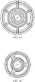
- Disclosed embodiments provide the selective annular seal to perform this operation in one trip, for example using an exemplary diverter tool as shown in FIGS. 1A-D .
- the tool device would be run above the motor, but below the spear, which is latched into the casing to be pulled. Circulation up the annulus during the cutting operation passes through the tool via annular flow passages below/through the packer cup (annulus) seal.
- a ball or other plug element can be dropped through the drill pipe/tool (e.g.
- packer cup as used in this application is intended to be broadly considered as any annulus seal element and is not merely limited to any specific packer cup embodiment, so the terms “packer cup” and “annulus seal element” may be used interchangeably).
- This essentially closes off possible flow up through the casing-drill pipe annulus. Flow down the drill pipe is now forced to enter the casing cut (e.g. through ports in the tool's housing exposed by upward movement of the seal sleeve) and travel back to the surface along the outside of the casing that is to be removed, as desired.
- the casing can be pulled from the well using the casing spear and jars run higher in the string.
- the closing mechanism of the tool prevents flow up the annulus once closed (e.g. due to sealing engagement of the molded seal with the packer cup), but may allow flow down the annulus by simply lifting the molded seal off the packer cup against the spring force. This feature may be useful to prevent possible fluid swabbing when the tool is removed from the casing when in the closed position (previously activated).
- FIGS. 1A-D illustrate such an exemplary diverter tool, which for example might be used in a downhole tool string within a cased wellbore.
- Fig. 1A shows the exemplary tool in its first configuration (with the activation sleeve in its first activation position and the seal sleeve in its first seal position), thereby preventing radial fluid flow from the bore outward through the housing into the annular space, while allowing longitudinal annular flow upward in the annular space through annular flow channels (e.g. allowing annular flow upward past the tool packer cup).
- Fig. 1A shows the exemplary tool in its first configuration (with the activation sleeve in its first activation position and the seal sleeve in its first seal position), thereby preventing radial fluid flow from the bore outward through the housing into the annular space, while allowing longitudinal annular flow upward in the annular space through annular flow channels (e.g. allowing annular flow upward past the tool packer cup).
- FIG. 1B shows the same tool in its second configuration (with the activation sleeve in its second activation position and the seal sleeve in its second seal position), thereby allowing radial fluid flow from the bore outward through the housing into the annular space, while preventing longitudinal annular flow upward in the annular space through the annular flow channels (e.g. preventing annular flow upward past the tool packer cup).
- the tool of FIGS. 1A-B comprises a housing 110 (typically having an outer diameter which is smaller than the inner diameter of the cased wellbore to be serviced) adapted to be made up as part of the tool string, with a longitudinal bore 112 therethrough and one or more ports 115 penetrating (radially) through the housing 110 (operable to allow fluid flow from the bore 112 to the annular space between the housing and the casing when open); a packer cup 120 affixed to the exterior of the housing 110 above the one or more ports 115 and operable to engage the casing (e.g.
- a seal sleeve 130 slidably disposed for longitudinal movement with respect to (e.g. outside) the housing 110 between a first (lower) seal position and a second (upper) seal position; a molded seal 133 (or other seal element), shaped to be operable to engage the packer cup 120 to seal the annular flow therethrough and attached to the seal sleeve 130 such that movement of the seal sleeve 130 (from its first position to its second position) results in movement of the molded seal 133 (from its first/lower/open position to its second/upper/closed position) (e.g.
- the seal 133 typically might be located at the top of the seal sleeve 130); an activation sleeve 140 (typically located within the bore 112 of the housing 110) slidably disposed for longitudinal movement with respect to (e.g. within) the housing 110 between a first (upper) activation position and a second (lower) activation position; and one or more retaining dog segments 142 operable to move radially within corresponding openings in the housing 110 from a first (outward) radial position to a second (inward) radial position.
- the packer cup typically is operable to engage (in a sealing manner) the casing (e.g. cased wellbore) and/or the housing.
- the packer cup/annulus seal element is typically operable to prevent fluid flow in the annular space between the housing and the cased wellbore (except through open annular flow channels), so that opening or closing the annular flow channels (e.g. based on position of the seal with respect to the annular flow channels) may operate to control annular fluid flow upward past the packer cup.
- the first position of the activation sleeve 140 is located to interact with the retaining dog segments 142 (e.g. the opening in the housing for the retaining dog segments, to prevent inward movement of the retaining dog segments) above the ports 115 in the housing (and to hold the retaining dog segments outward sufficiently so that the retaining dogs segments 142 interfere with (e.g. block/prevent) upward movement of the seal sleeve 130), and in FIG.
- the retaining dog segments 142 e.g. the opening in the housing for the retaining dog segments, to prevent inward movement of the retaining dog segments
- the ports 115 in the housing and to hold the retaining dog segments outward sufficiently so that the retaining dogs segments 142 interfere with (e.g. block/prevent) upward movement of the seal sleeve 130)
- the second position of the activation sleeve 140 is located below the ports 115 in the housing (to no longer interact with the retaining dog segments 142, thereby allowing the retaining dog segments freedom to move inward (for example, out of interference with the seal sleeve, thereby releasing the seal sleeve 130 for longitudinal movement), with the activation sleeve typically engaging a lip (e.g. necked-down portion of the bore) that may operate as a lower stop at its second position).
- a lip e.g. necked-down portion of the bore
- the first position of the seal sleeve 130 covers the ports 115 in the housing (thereby closing/sealing the ports) and locates the molded seal 133 below the packer cup 120 (in an open/non-engaging/non-sealing position, allowing annular flow upward through the annular space 122), and in FIG. 1B the second position of the seal sleeve 130 uncovers the ports 115 in the housing (to open the ports and allow fluid communication between the bore and the annular space) and locates the molded seal 133 to engage the packer cup 120 to seal the annular channels 122 through the packer cup.
- FIG. 1A the first position of the seal sleeve 130 covers the ports 115 in the housing (thereby closing/sealing the ports) and locates the molded seal 133 below the packer cup 120 (in an open/non-engaging/non-sealing position, allowing annular flow upward through the annular space 122)
- the first position of the retaining dog segments 142 is located to interact with both the activation sleeve 140 and the seal sleeve 130 (and is typically located between the activation sleeve and thee seal sleeve), with the retaining dog engaging the seal sleeve to hold it in its first position; and in FIG. 1B the second position of the retaining dog segments is retracted inward radially to release the seal sleeve (such that the retaining dog in its second position does not interact with either the activation sleeve or the seal sleeve, thereby allowing the seal sleeve freedom to move).
- the activation sleeve 140 is initially releasably held in its first position (e.g.
- the retaining dog 142 is initially held in its first position by the activation sleeve 140 in its first position (and moves from its first position to its second position when the activation sleeve moves from its first position to its second position); and the seal sleeve 130 is held in its first position by the retaining dog segments 142 in its first position, and the seal sleeve 130 is biased towards its second position (e.g. by a spring 135) (such that inward movement of the retaining dog to its second position releases the seal sleeve, allowing the seal sleeve to move to is second position due to biasing (e.g. spring) force).
- biasing e.g. spring
- activation of the activation sleeve 140 from its first position to its second position causes the activation sleeve 140 to slide downward in the housing 110 to a location below the ports 115, thereby releasing the retaining dog 142 to slide inward radially from its first position to its second position, thereby releasing the seal sleeve 130 so that the biasing force can slide the seal sleeve 130 upward on the housing 110 from its first position to its second position (in sealing contact with the packer cup to prevent fluid flow upward through the annular flow channels).
- activation of the activation sleeve 140 from its first position to its second position typically operates to shift/move/transform the tool from its first configuration to its second configuration.
- a ball 148 or plug element operable to seal the activation sleeve 140 may be used (in conjunction with fluid flow in the bore) to activate the activation sleeve, wherein the ball 148 may be operable to be placed in the upper end of the activation sleeve 140 to seal the sleeve (to prevent or restrict fluid flow through the opening of the activation sleeve), such that fluid flow through the bore then may drive the activation sleeve 140 from its first position to its second position.
- FIG. 1A prior to placement of the ball plug 148 (e.g. without the ball 148 in place), fluid flows through the bore 112 (from the top of the tool to the bottom of the tool - e.g. all fluid in the bore flows out the bottom of the tool), but after placement of the ball plug 148 in FIG. 1B (e.g. after placement of the ball and application of sufficient fluid pressure in the bore to drive the activation sleeve to its second position), fluid flows through the ports 115 in the housing.
- the tool Prior to placement of the ball plug 148, the tool is operable to allow fluid flow in the annular space between the housing and the casing up to the surface, but after placement of the ball plug 148 (e.g.
- the tool no longer allows annular fluid flow upward past the sealed packer cup 120.
- the activation sleeve 140 is releasably held in its first position by shear pins or screws 145.
- the seal sleeve 130 is typically biased upward towards its second position by a spring 135.
- the packer cup substantially retains its outward shape/diameter and is typically not designed to be collapsible or expandable (in other words, the packer cup typically maintains a substantially fixed outer diameter during deployment and operation of the tool).
- the outer diameter of the packer cup is typically approximately equal to the inner diameter of the casing, and is operable to sealingly engage with the casing (so that when the annular flow channels are closed, no fluid may flow upward past the packer cup).
- the activation sleeve 140 in its first position might also extend downward sufficiently to cover/close the ports 115 in the housing.
- the seal sleeve 130 in its first position covers the ports 115.
- some other releasable stop mechanism (other than retaining dog segments) might be used to releasably fix/hold the seal sleeve 130 in its first position (with such releasable stop mechanism typically being selectively released by movement of the activation sleeve from its first position to its second position in some embodiments).
- the seal sleeve would typically cover the ports 115 in the housing when located in its first seal position.
- some alternate embodiments not claimed herein may have annular flow channels that pass through a portion of the housing, rather than the packer cup.
- the annular flow channels could pass through either the packer cup or a portion of the housing (for example, a laterally extending portion of the housing) or (optionally) any other portion of the tool device, so long as the annular flow channels are capable of allowing longitudinal annular fluid flow in the annular space upward (for example, above the packer cup and/or upward to or toward the surface above the tool) when open.
- packer cup as used herein is to be considered in the broad sense as the equivalent of an annulus seal element (such that any annulus seal element might be used for various embodiments). Persons of skill will understand such alternate embodiment modifications (from Figs. 1A-B ) based on the description above.
- the diverter tool typically is used in a tool string, and (in addition to the diverter tool) the tool string may further comprise a cutter (for example, an expanding-blade cutter) and a motor, wherein the motor powers the cutter and the motor is operable to be powered by fluid flow through the tool string.
- the tool string may further comprise a spear (or other pulling tool for extracting the cut casing).
- the motor, cutter, and/or spear might be incorporated into the diverter tool itself.
- the motor and cutter are located below the ports, the seal sleeve, and/or the activation sleeve, and the motor is powered by fluid flow through the bore, which then circulates back to the surface through the annular space (between the tool string and the casing of the cased wellbore). So, the cutter cuts the casing when the tool is in its first configuration (e.g.
- a bottom seal may be used for the bottom of the wellbore (or somewhere below the cut in the wellbore), to facilitate fluid flow upward outside of the casing after cutting.
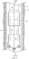
- FIG. 2 illustrates schematically typical placement of such a diverter tool 201 within a tool string 209 in a cased wellbore (relative to other tool string elements).
- the diverter tool 201 is located above the motor 202 and cutter 203 in the tool string 209, but typically would be located below the spear 205 (or other pulling tool for extracting the casing from the wellbore once cut).
- FIG. 2 merely shows the relative location of the specific tools/elements in the tool string in relation to one another (e.g. which is above and which is below); some embodiments may have other tools/elements interposed between the listed tools/elements. So in the tool string of FIG.
- fluid flow through the bore may power the motor 202 to drive the cutter 203 (cutting the casing). Fluid during cutting would typically flow downhole through the longitudinal bore in the tool string (all the way to the bottom - e.g. below the cutter) and then upward in the annular space 208 between the tool string 209 and the casing 207 (e.g. circulating back to the surface).
- the ball or other plug element can be inserted into the activation sleeve of the diverter tool 201.
- fluid flow in the bore of the tool string 209 can be used to force the activation sleeve downward into its second position (while also sealing the bore).
- fluid may then circulate upward along the outside of the casing 207 through the cut in the casing (for example, flowing from the bore, through the ports, downward in the annular space, through the cut in the casing, and upward along the outside of the casing), which may allow for cleanout of old drilling mud, solids, etc. that might complicate removal of the casing 207 from the wellbore.
- a drilling tool string 209 configured similar to that shown in FIG. 2 would thereby allow for cutting and pulling operations (to remove casing during well abandonment procedures for example) using only one trip of the tool string downhole.
- various additional embodiments may include, but are not limited to the following:
Landscapes
- Life Sciences & Earth Sciences (AREA)
- Engineering & Computer Science (AREA)
- Geology (AREA)
- Mining & Mineral Resources (AREA)
- Physics & Mathematics (AREA)
- Environmental & Geological Engineering (AREA)
- Fluid Mechanics (AREA)
- General Life Sciences & Earth Sciences (AREA)
- Geochemistry & Mineralogy (AREA)
- Marine Sciences & Fisheries (AREA)
- Pipe Accessories (AREA)
- Sawing (AREA)
Claims (12)
- Un outil de déviation (201) pour une utilisation dans un train d'outils de fond à l'intérieur d'un tubage (207) dans un puits de forage, l'outil (201) comprenant :un boîtier (110) adapté pour être constitué en tant que partie du train d'outils (209), avec un alésage longitudinal (112) à travers celui-ci, et un ou plusieurs orifices (115) qui pénètrent à travers le boîtier (110) pouvant être actionnés de manière à permettre un flux radial de fluide vers l'extérieur depuis l'alésage (112) vers un espace annulaire (208) entre le train d'outils (209) et le tubage (207) ;un garniture d'étanchéité de type gobelet (120) fixé à un extérieur du boîtier (110) au-dessus de l'un ou plusieurs orifices (115) et pouvant être actionné pour engager le tubage (207) et ayant un ou plusieurs canaux d'écoulement annulaires (122) à travers celui-ci ;un manchon d'étanchéité (130) situé à l'extérieur du boîtier (110) et disposé de manière coulissante pour un mouvement longitudinal par rapport au boîtier (110) entre une première position de joint et une seconde position de joint ;un joint d'étanchéité (133) conçu de manière à pouvoir être actionné pour engager la garniture d'étanchéité de type gobelet (120) pour sceller le flux annulaire à travers de celle-ci et fixé au manchon d'étanchéité (130), de telle sorte que le déplacement du manchon d'étanchéité (130) depuis la première position de joint vers la deuxième position de joint entraîne un déplacement du joint d'étanchéité (133) vers un engagement étanche avec le garniture d'étanchéité de type gobelet (120), caractérisé en ce que l'outil de déviation (201) comprend en outre :une gaine d'activation (140) située sur un intérieur du boîtier (110) et disposée de manière coulissante pour un déplacement longitudinal par rapport au boîtier (110) entre une première position d'activation et une seconde position d'activation ; etun ou plusieurs segments de crampon de retenue (142) pouvant être actionnés de manière à être déplacés radialement dans des ouvertures correspondantes dans le boîtier (110) depuis une première position radiale vers une seconde position radiale ;dans lequel:la première position d'activation de la gaine d'activation (140) est située pour interagir avec l'un ou plusieurs segments de crampon de retenue (142) au-dessus des orifices (115) dans le boîtier, et la seconde position d'activation de la gaine d'activation (140) est située au-dessous des orifices (115) dans le boîtier et n'interagit plus avec les segments de crampon de retenue (142) ;la première position de joint du manchon d'étanchéité (130) recouvre les orifices dans le boîtier (110) et situe le joint d'étanchéité (133) au-dessous de la garniture d'étanchéité de type gobelet (120), et la seconde position de joint du manchon d'étanchéité (130) révèle les orifices (115) dans le boîtier (110) de manière à permettre une communication fluidique entre l'alésage (112) et l'espace annulaire (208) et situe le joint d'étanchéité (133) pour engager la garniture d'étanchéité de type gobelet (120) pour sceller les canaux de flux annulaire (122) à travers la garniture d'étanchéité de type gobelet (120);la première position radiale de l'un ou plusieurs segments de crampon de retenue (142) interagit avec la gaine d'activation (140) et le manchon d'étanchéité (130), avec l'un ou plusieurs segments de crampon de retenue (142) engageant le manchon d'étanchéité (130) pour maintenir le manchon d'étanchéité (130) dans la première position de joint, et la seconde position radiale de l'un ou plusieurs segments de crampon de retenue (142) est retiré vers l'intérieur radialement pour libérer le manchon d'étanchéité (130) ;le manchon de la gaine d'activation (140) est initialement maintenu de manière libérable dans sa première position d'activation;l'un ou plusieurs segments de crampon de retenue (142) sont initialement maintenus dans la première position radiale par la gaine d'activation (140) dans la première position d'activation et sont déplacés depuis la première position radiale vers la seconde position radiale lorsque la gaine d'activation (140) est déplacée depuis la première position d'activation vers la seconde position d'activation; etle manchon d'étanchéité (130) est maintenu dans la première position de joint par l'un ou plusieurs segments de crampon de retenue (142) dans la première position radiale, et le manchon d'étanchéité (130) est polarisé vers la seconde position de joint, de sorte qu'un déplacement radial de l'un ou plusieurs segments de crampon de retenue (142) vers la seconde position radiale libère le manchon d'étanchéité (130) et permet à la gaine d'étanchéité (130) d'être déplacée vers la seconde position de joint.
- L'outil de déviation (201) de la revendication 1, dans lequel l'activation de la gaine d'activation (140) depuis la première position d'activation vers la seconde position d'activation entraîne un coulissement vers le bas de la gaine d'activation (140) dans le boitier (110) vers un endroit en dessous des orifices (115), ainsi libérant l'un ou plusieurs segments de crampon de retenue (142) pour coulisser radialement vers l'intérieur depuis la première position radiale vers la seconde position radiale, ainsi libérant le manchon d'étanchéité (130) de sorte que la force polarisante puisse coulisser le manchon d'étanchéité (130) vers le haut sur le boîtier (110) depuis la première position de joint vers la seconde position de joint.
- L'outil de déviation (201) de la revendication 1 ou 2, comprenant en outre une balle (148) actionnable pour sceller la gaine d'activation (140), dans lequel la balle (148) peut être actionnée pour être placée dans l'extrémité supérieure de la gaine d'activation (140) pour sceller la gaine d'activation (140), de sorte que le flux de fluide à travers l'alésage (112) puisse alors entrainer la gaine d'activation (140) depuis une première position d'activation vers la seconde position d'activation.
- L'outil de déviation (201) de la revendication 3, dans lequel préalablement au placement de la balle (148), un fluide est actionnable pour s'écouler à travers l'alésage (112) depuis le haut de l'outil (201) vers le bas de l'outil (201), mais après le placement de la balle (148), un fluide est actionnable pour s'écouler à travers les orifices (115) dans le boîtier (110).
- L'outil de déviation (201) de la revendication 3 ou 4, dans lequel préalablement au placement de la balle (148), l'outil (201) est actionnable pour permettre un flux de fluide dans l'espace annulaire (208) entre le boîtier (110) et le tubage (207) jusqu'à la surface, mais après le placement de la balle (148), l'outil (201) ne permet plus un flux de fluide annulaire vers le haut au-delà de la garniture d'étanchéité de type gobelet scellée (120).
- L'outil de déviation (201) selon l'une quelconque des revendications 1 à 5, dans lequel la gaine d'activation (140) est maintenue de manière libérable dans sa première position par des goupilles de cisaillement ou des vis (145).
- L'outil de déviation (201) selon l'une quelconque des revendications 1 à 6, dans lequel le manchon d'étanchéité (130) est polarisé vers le haut vers sa seconde position au moyen d'un ressort (135).
- L'outil de déviation (201) selon l'une quelconque des revendications 1 à 7, comprenant en outre un sectionneur (203) et un moteur (202), dans lequel le moteur (202) entraîne le sectionneur (203) et le moteur (202) est actionnable pour être entraîné par un flux de fluide à travers le train d'outils (209).
- L'outil de déviation (201) selon la revendication 8, dans lequel le moteur (202) et le sectionneur (203) sont situés au-dessous des orifices (115), du manchon d'étanchéité (130), et de la gaine d'activation (140); et/ou le moteur (202) est entraîné par un flux de fluide à travers l'alésage (112), qui alors circule de retour vers la surface à travers de l'espace annulaire (208).
- L'outil de déviation (201) de la revendication 8 ou 9, dans lequel le sectionneur (203) sectionne le tubage (207) avant qu'une balle (148) est placée dans la gaine d'activation (140), et dans lequel, du moment où le balle (148) est en place scellant la gaine d'activation (140) et déplaçant la gaine d'activation (140) et donc le manchon d'étanchéité (130) depuis leur première position vers leur seconde position, un fluide s'écoule vers le bas à travers l'alésage (112) vers les orifices (115), vers l'extérieur à travers les orifices (115) vers l'espace annulaire (208), vers le bas dans l'espace annulaire (208) pour sortir du boîtier (207) au niveau de la section, pour ainsi s'écouler de retour vers le haut en direction de la surface le long de l'extérieur du tubage (207).
- L'outil de déviation (201) selon la revendication 8, 9 ou 10, comprenant en outre une lance (205) pour extraire le tubage sectionné (207).
- L'outil de déviation (201) selon l'une quelconque des revendications 1 à 11, comprenant en outre un joint de fond pour le fond du puits de forage.
Applications Claiming Priority (2)
| Application Number | Priority Date | Filing Date | Title |
|---|---|---|---|
| US201361903641P | 2013-11-13 | 2013-11-13 | |
| PCT/US2014/065494 WO2015073695A2 (fr) | 2013-11-13 | 2014-11-13 | Appareil et système de découpe et de retrait en un seul déplacement |
Publications (3)
| Publication Number | Publication Date |
|---|---|
| EP3068970A2 EP3068970A2 (fr) | 2016-09-21 |
| EP3068970A4 EP3068970A4 (fr) | 2017-07-19 |
| EP3068970B1 true EP3068970B1 (fr) | 2018-10-17 |
Family
ID=53058257
Family Applications (1)
| Application Number | Title | Priority Date | Filing Date |
|---|---|---|---|
| EP14862576.7A Active EP3068970B1 (fr) | 2013-11-13 | 2014-11-13 | Appareil et système de découpe et de retrait en un seul déplacement |
Country Status (3)
| Country | Link |
|---|---|
| US (1) | US10024127B2 (fr) |
| EP (1) | EP3068970B1 (fr) |
| WO (1) | WO2015073695A2 (fr) |
Families Citing this family (8)
| Publication number | Priority date | Publication date | Assignee | Title |
|---|---|---|---|---|
| US9464496B2 (en) * | 2013-03-05 | 2016-10-11 | Smith International, Inc. | Downhole tool for removing a casing portion |
| US10024127B2 (en) | 2013-11-13 | 2018-07-17 | Hydrawell Inc. | One-trip cut and pull system and apparatus |
| WO2015200397A1 (fr) * | 2014-06-25 | 2015-12-30 | Schlumberger Canada Limited | Outil de commande d'écoulement de forage |
| GB2561814B (en) | 2016-10-10 | 2019-05-15 | Ardyne Holdings Ltd | Downhole test tool and method of use |
| US10458196B2 (en) | 2017-03-09 | 2019-10-29 | Weatherford Technology Holdings, Llc | Downhole casing pulling tool |
| US11248428B2 (en) | 2019-02-07 | 2022-02-15 | Weatherford Technology Holdings, Llc | Wellbore apparatus for setting a downhole tool |
| CN111021973B (zh) * | 2019-12-18 | 2023-10-31 | 中国石油天然气股份有限公司 | 一种捕收球式适配器及其安装方法 |
| US11408241B2 (en) * | 2020-07-31 | 2022-08-09 | Baker Hughes Oilfield Operations Llc | Downhole pulling tool with selective anchor actuation |
Family Cites Families (17)
| Publication number | Priority date | Publication date | Assignee | Title |
|---|---|---|---|---|
| US2203011A (en) | 1937-04-08 | 1940-06-04 | Guy P Ellis | Pipe cutter |
| US2786534A (en) * | 1953-05-14 | 1957-03-26 | Jr John S Page | Well tool |
| US3771603A (en) * | 1972-04-13 | 1973-11-13 | Baker Oil Tools Inc | Dual safety valve method and apparatus |
| NO802998L (no) * | 1979-12-27 | 1981-06-29 | Halliburton Co | Ventilverktoey for broennhull. |
| GB8514887D0 (en) * | 1985-06-12 | 1985-07-17 | Smedvig Peder As | Down-hole blow-out preventers |
| US5181569A (en) * | 1992-03-23 | 1993-01-26 | Otis Engineering Corporation | Pressure operated valve |
| US7357188B1 (en) * | 1998-12-07 | 2008-04-15 | Shell Oil Company | Mono-diameter wellbore casing |
| CA2265223C (fr) * | 1999-03-11 | 2004-05-18 | Linden H. Bland | Dispositif et methode d'installation de packer pour anneau torique de puits de forage |
| US6802372B2 (en) * | 2002-07-30 | 2004-10-12 | Weatherford/Lamb, Inc. | Apparatus for releasing a ball into a wellbore |
| WO2007140612A1 (fr) * | 2006-06-06 | 2007-12-13 | Tesco Corporation | Outils et procédés utilisables avec une circulation inversée dans un puits de forage |
| AR062973A1 (es) * | 2007-09-25 | 2008-12-17 | Carro Gustavo Ignacio | Paquer recuperable para operaciones en pozos entubados |
| US8540035B2 (en) | 2008-05-05 | 2013-09-24 | Weatherford/Lamb, Inc. | Extendable cutting tools for use in a wellbore |
| CA2641778A1 (fr) * | 2008-10-14 | 2010-04-14 | Source Energy Tool Services Inc. | Procede et appareil de fracturation selective d'un puits |
| US8893791B2 (en) | 2011-08-31 | 2014-11-25 | Baker Hughes Incorporated | Multi-position mechanical spear for multiple tension cuts with releasable locking feature |
| US9464496B2 (en) | 2013-03-05 | 2016-10-11 | Smith International, Inc. | Downhole tool for removing a casing portion |
| US10024127B2 (en) | 2013-11-13 | 2018-07-17 | Hydrawell Inc. | One-trip cut and pull system and apparatus |
| US20160130901A1 (en) | 2014-11-12 | 2016-05-12 | Hydrawell Inc. | Multi-Acting Circulation Tool for One-Trip Casing Cut-and-Pull |
-
2014
- 2014-11-13 US US15/034,830 patent/US10024127B2/en active Active
- 2014-11-13 EP EP14862576.7A patent/EP3068970B1/fr active Active
- 2014-11-13 WO PCT/US2014/065494 patent/WO2015073695A2/fr not_active Ceased
Non-Patent Citations (1)
| Title |
|---|
| None * |
Also Published As
| Publication number | Publication date |
|---|---|
| EP3068970A4 (fr) | 2017-07-19 |
| WO2015073695A3 (fr) | 2015-11-19 |
| EP3068970A2 (fr) | 2016-09-21 |
| US20160265295A1 (en) | 2016-09-15 |
| WO2015073695A2 (fr) | 2015-05-21 |
| US10024127B2 (en) | 2018-07-17 |
Similar Documents
| Publication | Publication Date | Title |
|---|---|---|
| EP3068970B1 (fr) | Appareil et système de découpe et de retrait en un seul déplacement | |
| US9464496B2 (en) | Downhole tool for removing a casing portion | |
| CA3025106C (fr) | Vanne de derivation destinee a un assemblage de fond de trou | |
| CA2924287C (fr) | Outil de fond de trou recuperable | |
| US8869896B2 (en) | Multi-position mechanical spear for multiple tension cuts while removing cuttings | |
| EP2697478B1 (fr) | Cimentation etagée a l'aide d'un outil à vanne à manchon coulissant | |
| US7857052B2 (en) | Stage cementing methods used in casing while drilling | |
| EP3619390B1 (fr) | Améliorations apportées ou se rapportant à l'abandon de puits et à la récupération de fentes | |
| AU2012256291B2 (en) | Tubular cutting with a sealed annular space and fluid flow for cuttings removal | |
| US10508510B2 (en) | Bottom hole assembly for cutting and pulling a tubular | |
| CA2905339C (fr) | Siege de rotule extensible pour des outils a actionnement hydraulique | |
| US8881818B2 (en) | Tubular cutting with debris filtration | |
| EP3388617B1 (fr) | Système de coiffe pour arborescence sous-marine déployable via un véhicule actionné à distance | |
| CA2960731C (fr) | Outil etage | |
| EP3784873B1 (fr) | Train d'outils de reconditionnement | |
| US20160130901A1 (en) | Multi-Acting Circulation Tool for One-Trip Casing Cut-and-Pull | |
| CA2924015A1 (fr) | Manchon d'amorcage ameliore a bout de lancement sans mandrin | |
| EP2723978B1 (fr) | Outil de rinçage et procédé de rinçage de tubage perforé | |
| CA2924084A1 (fr) | Garniture d'amorcage de la fracturation (tis) sans mandrin | |
| US20160245033A1 (en) | Tool and method of operation for removing debris and/or a lodged tool from a wellbore | |
| RU2806885C2 (ru) | Скважинная перекрывающая система, скважинная система, содержащая такую скважинную перекрывающую систему, и способ герметизации поврежденной зоны скважинной трубчатой металлической конструкции | |
| EP3803031B1 (fr) | Système d'exécution de fond de trou | |
| GB2275069A (en) | Down hole installations |
Legal Events
| Date | Code | Title | Description |
|---|---|---|---|
| PUAI | Public reference made under article 153(3) epc to a published international application that has entered the european phase |
Free format text: ORIGINAL CODE: 0009012 |
|
| 17P | Request for examination filed |
Effective date: 20160602 |
|
| AK | Designated contracting states |
Kind code of ref document: A2 Designated state(s): AL AT BE BG CH CY CZ DE DK EE ES FI FR GB GR HR HU IE IS IT LI LT LU LV MC MK MT NL NO PL PT RO RS SE SI SK SM TR |
|
| AX | Request for extension of the european patent |
Extension state: BA ME |
|
| RIN1 | Information on inventor provided before grant (corrected) |
Inventor name: IUELL, MARKUS Inventor name: PLANTE, MARK Inventor name: GARCIA, LUIS Inventor name: CORONADO, MARTIN P. Inventor name: BENNETT, RODNEY |
|
| DAX | Request for extension of the european patent (deleted) | ||
| A4 | Supplementary search report drawn up and despatched |
Effective date: 20170616 |
|
| RIC1 | Information provided on ipc code assigned before grant |
Ipc: E21B 33/126 20060101ALI20170609BHEP Ipc: E21B 23/12 20060101AFI20170609BHEP Ipc: E21B 33/10 20060101ALI20170609BHEP |
|
| REG | Reference to a national code |
Ref country code: DE Ref legal event code: R079 Ref document number: 602014034424 Country of ref document: DE Free format text: PREVIOUS MAIN CLASS: E21B0023120000 Ipc: E21B0029000000 |
|
| RIC1 | Information provided on ipc code assigned before grant |
Ipc: E21B 29/00 20060101AFI20180404BHEP Ipc: E21B 31/16 20060101ALI20180404BHEP Ipc: E21B 34/14 20060101ALI20180404BHEP |
|
| GRAP | Despatch of communication of intention to grant a patent |
Free format text: ORIGINAL CODE: EPIDOSNIGR1 |
|
| INTG | Intention to grant announced |
Effective date: 20180514 |
|
| GRAS | Grant fee paid |
Free format text: ORIGINAL CODE: EPIDOSNIGR3 |
|
| GRAA | (expected) grant |
Free format text: ORIGINAL CODE: 0009210 |
|
| AK | Designated contracting states |
Kind code of ref document: B1 Designated state(s): AL AT BE BG CH CY CZ DE DK EE ES FI FR GB GR HR HU IE IS IT LI LT LU LV MC MK MT NL NO PL PT RO RS SE SI SK SM TR |
|
| REG | Reference to a national code |
Ref country code: GB Ref legal event code: FG4D |
|
| REG | Reference to a national code |
Ref country code: CH Ref legal event code: EP |
|
| REG | Reference to a national code |
Ref country code: IE Ref legal event code: FG4D |
|
| REG | Reference to a national code |
Ref country code: DE Ref legal event code: R096 Ref document number: 602014034424 Country of ref document: DE Ref country code: AT Ref legal event code: REF Ref document number: 1054251 Country of ref document: AT Kind code of ref document: T Effective date: 20181115 |
|
| REG | Reference to a national code |
Ref country code: NL Ref legal event code: FP |
|
| REG | Reference to a national code |
Ref country code: LT Ref legal event code: MG4D |
|
| REG | Reference to a national code |
Ref country code: AT Ref legal event code: MK05 Ref document number: 1054251 Country of ref document: AT Kind code of ref document: T Effective date: 20181017 |
|
| PG25 | Lapsed in a contracting state [announced via postgrant information from national office to epo] |
Ref country code: NO Free format text: LAPSE BECAUSE OF FAILURE TO SUBMIT A TRANSLATION OF THE DESCRIPTION OR TO PAY THE FEE WITHIN THE PRESCRIBED TIME-LIMIT Effective date: 20190117 Ref country code: BG Free format text: LAPSE BECAUSE OF FAILURE TO SUBMIT A TRANSLATION OF THE DESCRIPTION OR TO PAY THE FEE WITHIN THE PRESCRIBED TIME-LIMIT Effective date: 20190117 Ref country code: FI Free format text: LAPSE BECAUSE OF FAILURE TO SUBMIT A TRANSLATION OF THE DESCRIPTION OR TO PAY THE FEE WITHIN THE PRESCRIBED TIME-LIMIT Effective date: 20181017 Ref country code: IS Free format text: LAPSE BECAUSE OF FAILURE TO SUBMIT A TRANSLATION OF THE DESCRIPTION OR TO PAY THE FEE WITHIN THE PRESCRIBED TIME-LIMIT Effective date: 20190217 Ref country code: LT Free format text: LAPSE BECAUSE OF FAILURE TO SUBMIT A TRANSLATION OF THE DESCRIPTION OR TO PAY THE FEE WITHIN THE PRESCRIBED TIME-LIMIT Effective date: 20181017 Ref country code: LV Free format text: LAPSE BECAUSE OF FAILURE TO SUBMIT A TRANSLATION OF THE DESCRIPTION OR TO PAY THE FEE WITHIN THE PRESCRIBED TIME-LIMIT Effective date: 20181017 Ref country code: PL Free format text: LAPSE BECAUSE OF FAILURE TO SUBMIT A TRANSLATION OF THE DESCRIPTION OR TO PAY THE FEE WITHIN THE PRESCRIBED TIME-LIMIT Effective date: 20181017 Ref country code: HR Free format text: LAPSE BECAUSE OF FAILURE TO SUBMIT A TRANSLATION OF THE DESCRIPTION OR TO PAY THE FEE WITHIN THE PRESCRIBED TIME-LIMIT Effective date: 20181017 Ref country code: ES Free format text: LAPSE BECAUSE OF FAILURE TO SUBMIT A TRANSLATION OF THE DESCRIPTION OR TO PAY THE FEE WITHIN THE PRESCRIBED TIME-LIMIT Effective date: 20181017 Ref country code: AT Free format text: LAPSE BECAUSE OF FAILURE TO SUBMIT A TRANSLATION OF THE DESCRIPTION OR TO PAY THE FEE WITHIN THE PRESCRIBED TIME-LIMIT Effective date: 20181017 |
|
| PG25 | Lapsed in a contracting state [announced via postgrant information from national office to epo] |
Ref country code: GR Free format text: LAPSE BECAUSE OF FAILURE TO SUBMIT A TRANSLATION OF THE DESCRIPTION OR TO PAY THE FEE WITHIN THE PRESCRIBED TIME-LIMIT Effective date: 20190118 Ref country code: PT Free format text: LAPSE BECAUSE OF FAILURE TO SUBMIT A TRANSLATION OF THE DESCRIPTION OR TO PAY THE FEE WITHIN THE PRESCRIBED TIME-LIMIT Effective date: 20190217 Ref country code: RS Free format text: LAPSE BECAUSE OF FAILURE TO SUBMIT A TRANSLATION OF THE DESCRIPTION OR TO PAY THE FEE WITHIN THE PRESCRIBED TIME-LIMIT Effective date: 20181017 Ref country code: SE Free format text: LAPSE BECAUSE OF FAILURE TO SUBMIT A TRANSLATION OF THE DESCRIPTION OR TO PAY THE FEE WITHIN THE PRESCRIBED TIME-LIMIT Effective date: 20181017 Ref country code: AL Free format text: LAPSE BECAUSE OF FAILURE TO SUBMIT A TRANSLATION OF THE DESCRIPTION OR TO PAY THE FEE WITHIN THE PRESCRIBED TIME-LIMIT Effective date: 20181017 |
|
| REG | Reference to a national code |
Ref country code: CH Ref legal event code: PL |
|
| REG | Reference to a national code |
Ref country code: DE Ref legal event code: R097 Ref document number: 602014034424 Country of ref document: DE |
|
| PG25 | Lapsed in a contracting state [announced via postgrant information from national office to epo] |
Ref country code: IT Free format text: LAPSE BECAUSE OF FAILURE TO SUBMIT A TRANSLATION OF THE DESCRIPTION OR TO PAY THE FEE WITHIN THE PRESCRIBED TIME-LIMIT Effective date: 20181017 Ref country code: DK Free format text: LAPSE BECAUSE OF FAILURE TO SUBMIT A TRANSLATION OF THE DESCRIPTION OR TO PAY THE FEE WITHIN THE PRESCRIBED TIME-LIMIT Effective date: 20181017 Ref country code: LU Free format text: LAPSE BECAUSE OF NON-PAYMENT OF DUE FEES Effective date: 20181113 Ref country code: CZ Free format text: LAPSE BECAUSE OF FAILURE TO SUBMIT A TRANSLATION OF THE DESCRIPTION OR TO PAY THE FEE WITHIN THE PRESCRIBED TIME-LIMIT Effective date: 20181017 |
|
| REG | Reference to a national code |
Ref country code: BE Ref legal event code: MM Effective date: 20181130 |
|
| PLBE | No opposition filed within time limit |
Free format text: ORIGINAL CODE: 0009261 |
|
| STAA | Information on the status of an ep patent application or granted ep patent |
Free format text: STATUS: NO OPPOSITION FILED WITHIN TIME LIMIT |
|
| PG25 | Lapsed in a contracting state [announced via postgrant information from national office to epo] |
Ref country code: MC Free format text: LAPSE BECAUSE OF FAILURE TO SUBMIT A TRANSLATION OF THE DESCRIPTION OR TO PAY THE FEE WITHIN THE PRESCRIBED TIME-LIMIT Effective date: 20181017 Ref country code: CH Free format text: LAPSE BECAUSE OF NON-PAYMENT OF DUE FEES Effective date: 20181130 Ref country code: SK Free format text: LAPSE BECAUSE OF FAILURE TO SUBMIT A TRANSLATION OF THE DESCRIPTION OR TO PAY THE FEE WITHIN THE PRESCRIBED TIME-LIMIT Effective date: 20181017 Ref country code: RO Free format text: LAPSE BECAUSE OF FAILURE TO SUBMIT A TRANSLATION OF THE DESCRIPTION OR TO PAY THE FEE WITHIN THE PRESCRIBED TIME-LIMIT Effective date: 20181017 Ref country code: EE Free format text: LAPSE BECAUSE OF FAILURE TO SUBMIT A TRANSLATION OF THE DESCRIPTION OR TO PAY THE FEE WITHIN THE PRESCRIBED TIME-LIMIT Effective date: 20181017 Ref country code: SM Free format text: LAPSE BECAUSE OF FAILURE TO SUBMIT A TRANSLATION OF THE DESCRIPTION OR TO PAY THE FEE WITHIN THE PRESCRIBED TIME-LIMIT Effective date: 20181017 Ref country code: LI Free format text: LAPSE BECAUSE OF NON-PAYMENT OF DUE FEES Effective date: 20181130 |
|
| 26N | No opposition filed |
Effective date: 20190718 |
|
| PG25 | Lapsed in a contracting state [announced via postgrant information from national office to epo] |
Ref country code: SI Free format text: LAPSE BECAUSE OF FAILURE TO SUBMIT A TRANSLATION OF THE DESCRIPTION OR TO PAY THE FEE WITHIN THE PRESCRIBED TIME-LIMIT Effective date: 20181017 |
|
| PG25 | Lapsed in a contracting state [announced via postgrant information from national office to epo] |
Ref country code: BE Free format text: LAPSE BECAUSE OF NON-PAYMENT OF DUE FEES Effective date: 20181130 |
|
| PG25 | Lapsed in a contracting state [announced via postgrant information from national office to epo] |
Ref country code: MT Free format text: LAPSE BECAUSE OF NON-PAYMENT OF DUE FEES Effective date: 20181113 |
|
| PG25 | Lapsed in a contracting state [announced via postgrant information from national office to epo] |
Ref country code: TR Free format text: LAPSE BECAUSE OF FAILURE TO SUBMIT A TRANSLATION OF THE DESCRIPTION OR TO PAY THE FEE WITHIN THE PRESCRIBED TIME-LIMIT Effective date: 20181017 |
|
| PG25 | Lapsed in a contracting state [announced via postgrant information from national office to epo] |
Ref country code: MK Free format text: LAPSE BECAUSE OF NON-PAYMENT OF DUE FEES Effective date: 20181017 Ref country code: CY Free format text: LAPSE BECAUSE OF FAILURE TO SUBMIT A TRANSLATION OF THE DESCRIPTION OR TO PAY THE FEE WITHIN THE PRESCRIBED TIME-LIMIT Effective date: 20181017 Ref country code: HU Free format text: LAPSE BECAUSE OF FAILURE TO SUBMIT A TRANSLATION OF THE DESCRIPTION OR TO PAY THE FEE WITHIN THE PRESCRIBED TIME-LIMIT; INVALID AB INITIO Effective date: 20141113 |
|
| PGFP | Annual fee paid to national office [announced via postgrant information from national office to epo] |
Ref country code: IE Payment date: 20221114 Year of fee payment: 9 Ref country code: FR Payment date: 20221114 Year of fee payment: 9 |
|
| P01 | Opt-out of the competence of the unified patent court (upc) registered |
Effective date: 20230524 |
|
| REG | Reference to a national code |
Ref country code: IE Ref legal event code: MM4A |
|
| PG25 | Lapsed in a contracting state [announced via postgrant information from national office to epo] |
Ref country code: IE Free format text: LAPSE BECAUSE OF NON-PAYMENT OF DUE FEES Effective date: 20231113 |
|
| PG25 | Lapsed in a contracting state [announced via postgrant information from national office to epo] |
Ref country code: FR Free format text: LAPSE BECAUSE OF NON-PAYMENT OF DUE FEES Effective date: 20231130 |
|
| PG25 | Lapsed in a contracting state [announced via postgrant information from national office to epo] |
Ref country code: IE Free format text: LAPSE BECAUSE OF NON-PAYMENT OF DUE FEES Effective date: 20231113 Ref country code: FR Free format text: LAPSE BECAUSE OF NON-PAYMENT OF DUE FEES Effective date: 20231130 |
|
| PGFP | Annual fee paid to national office [announced via postgrant information from national office to epo] |
Ref country code: NL Payment date: 20251120 Year of fee payment: 12 |
|
| PGFP | Annual fee paid to national office [announced via postgrant information from national office to epo] |
Ref country code: DE Payment date: 20251114 Year of fee payment: 12 |
|
| PGFP | Annual fee paid to national office [announced via postgrant information from national office to epo] |
Ref country code: GB Payment date: 20251106 Year of fee payment: 12 |