EP3068997B1 - Segmentierte dichtung für gasturbinenmotor - Google Patents
Segmentierte dichtung für gasturbinenmotor Download PDFInfo
- Publication number
- EP3068997B1 EP3068997B1 EP14881671.3A EP14881671A EP3068997B1 EP 3068997 B1 EP3068997 B1 EP 3068997B1 EP 14881671 A EP14881671 A EP 14881671A EP 3068997 B1 EP3068997 B1 EP 3068997B1
- Authority
- EP
- European Patent Office
- Prior art keywords
- segmented seal
- gas turbine
- seal
- turbine engine
- recited
- Prior art date
- Legal status (The legal status is an assumption and is not a legal conclusion. Google has not performed a legal analysis and makes no representation as to the accuracy of the status listed.)
- Active
Links
Images


Classifications
-
- F—MECHANICAL ENGINEERING; LIGHTING; HEATING; WEAPONS; BLASTING
- F01—MACHINES OR ENGINES IN GENERAL; ENGINE PLANTS IN GENERAL; STEAM ENGINES
- F01D—NON-POSITIVE DISPLACEMENT MACHINES OR ENGINES, e.g. STEAM TURBINES
- F01D11/00—Preventing or minimising internal leakage of working-fluid, e.g. between stages
- F01D11/005—Sealing means between non relatively rotating elements
-
- F—MECHANICAL ENGINEERING; LIGHTING; HEATING; WEAPONS; BLASTING
- F01—MACHINES OR ENGINES IN GENERAL; ENGINE PLANTS IN GENERAL; STEAM ENGINES
- F01D—NON-POSITIVE DISPLACEMENT MACHINES OR ENGINES, e.g. STEAM TURBINES
- F01D11/00—Preventing or minimising internal leakage of working-fluid, e.g. between stages
- F01D11/001—Preventing or minimising internal leakage of working-fluid, e.g. between stages for sealing space between stator blade and rotor
-
- F—MECHANICAL ENGINEERING; LIGHTING; HEATING; WEAPONS; BLASTING
- F01—MACHINES OR ENGINES IN GENERAL; ENGINE PLANTS IN GENERAL; STEAM ENGINES
- F01D—NON-POSITIVE DISPLACEMENT MACHINES OR ENGINES, e.g. STEAM TURBINES
- F01D11/00—Preventing or minimising internal leakage of working-fluid, e.g. between stages
- F01D11/02—Preventing or minimising internal leakage of working-fluid, e.g. between stages by non-contact sealings, e.g. of labyrinth type
-
- F—MECHANICAL ENGINEERING; LIGHTING; HEATING; WEAPONS; BLASTING
- F01—MACHINES OR ENGINES IN GENERAL; ENGINE PLANTS IN GENERAL; STEAM ENGINES
- F01D—NON-POSITIVE DISPLACEMENT MACHINES OR ENGINES, e.g. STEAM TURBINES
- F01D5/00—Blades; Blade-carrying members; Heating, heat-insulating, cooling or antivibration means on the blades or the members
- F01D5/02—Blade-carrying members, e.g. rotors
- F01D5/06—Rotors for more than one axial stage, e.g. of drum or multiple disc type; Details thereof, e.g. shafts, shaft connections
-
- F—MECHANICAL ENGINEERING; LIGHTING; HEATING; WEAPONS; BLASTING
- F01—MACHINES OR ENGINES IN GENERAL; ENGINE PLANTS IN GENERAL; STEAM ENGINES
- F01D—NON-POSITIVE DISPLACEMENT MACHINES OR ENGINES, e.g. STEAM TURBINES
- F01D5/00—Blades; Blade-carrying members; Heating, heat-insulating, cooling or antivibration means on the blades or the members
- F01D5/02—Blade-carrying members, e.g. rotors
- F01D5/08—Heating, heat-insulating or cooling means
- F01D5/081—Cooling fluid being directed on the side of the rotor disc or at the roots of the blades
-
- F—MECHANICAL ENGINEERING; LIGHTING; HEATING; WEAPONS; BLASTING
- F01—MACHINES OR ENGINES IN GENERAL; ENGINE PLANTS IN GENERAL; STEAM ENGINES
- F01D—NON-POSITIVE DISPLACEMENT MACHINES OR ENGINES, e.g. STEAM TURBINES
- F01D9/00—Stators
- F01D9/02—Nozzles; Nozzle boxes; Stator blades; Guide conduits, e.g. individual nozzles
- F01D9/04—Nozzles; Nozzle boxes; Stator blades; Guide conduits, e.g. individual nozzles forming ring or sector
- F01D9/041—Nozzles; Nozzle boxes; Stator blades; Guide conduits, e.g. individual nozzles forming ring or sector using blades
-
- F—MECHANICAL ENGINEERING; LIGHTING; HEATING; WEAPONS; BLASTING
- F05—INDEXING SCHEMES RELATING TO ENGINES OR PUMPS IN VARIOUS SUBCLASSES OF CLASSES F01-F04
- F05D—INDEXING SCHEME FOR ASPECTS RELATING TO NON-POSITIVE-DISPLACEMENT MACHINES OR ENGINES, GAS-TURBINES OR JET-PROPULSION PLANTS
- F05D2220/00—Application
- F05D2220/30—Application in turbines
- F05D2220/32—Application in turbines in gas turbines
-
- F—MECHANICAL ENGINEERING; LIGHTING; HEATING; WEAPONS; BLASTING
- F05—INDEXING SCHEMES RELATING TO ENGINES OR PUMPS IN VARIOUS SUBCLASSES OF CLASSES F01-F04
- F05D—INDEXING SCHEME FOR ASPECTS RELATING TO NON-POSITIVE-DISPLACEMENT MACHINES OR ENGINES, GAS-TURBINES OR JET-PROPULSION PLANTS
- F05D2240/00—Components
- F05D2240/55—Seals
- F05D2240/57—Leaf seals
-
- F—MECHANICAL ENGINEERING; LIGHTING; HEATING; WEAPONS; BLASTING
- F05—INDEXING SCHEMES RELATING TO ENGINES OR PUMPS IN VARIOUS SUBCLASSES OF CLASSES F01-F04
- F05D—INDEXING SCHEME FOR ASPECTS RELATING TO NON-POSITIVE-DISPLACEMENT MACHINES OR ENGINES, GAS-TURBINES OR JET-PROPULSION PLANTS
- F05D2240/00—Components
- F05D2240/80—Platforms for stationary or moving blades
-
- F—MECHANICAL ENGINEERING; LIGHTING; HEATING; WEAPONS; BLASTING
- F05—INDEXING SCHEMES RELATING TO ENGINES OR PUMPS IN VARIOUS SUBCLASSES OF CLASSES F01-F04
- F05D—INDEXING SCHEME FOR ASPECTS RELATING TO NON-POSITIVE-DISPLACEMENT MACHINES OR ENGINES, GAS-TURBINES OR JET-PROPULSION PLANTS
- F05D2260/00—Function
- F05D2260/30—Retaining components in desired mutual position
-
- Y—GENERAL TAGGING OF NEW TECHNOLOGICAL DEVELOPMENTS; GENERAL TAGGING OF CROSS-SECTIONAL TECHNOLOGIES SPANNING OVER SEVERAL SECTIONS OF THE IPC; TECHNICAL SUBJECTS COVERED BY FORMER USPC CROSS-REFERENCE ART COLLECTIONS [XRACs] AND DIGESTS
- Y02—TECHNOLOGIES OR APPLICATIONS FOR MITIGATION OR ADAPTATION AGAINST CLIMATE CHANGE
- Y02T—CLIMATE CHANGE MITIGATION TECHNOLOGIES RELATED TO TRANSPORTATION
- Y02T50/00—Aeronautics or air transport
- Y02T50/60—Efficient propulsion technologies, e.g. for aircraft
Definitions
- Gas turbine engines typically include a compressor section, a combustor section and a turbine section. During operation, air is pressurized in the compressor section and is mixed with fuel and burned in the combustor section to generate hot combustion gases. The hot combustion gases are communicated through the turbine section, which extracts energy from the hot combustion gases to power the compressor section and other gas turbine engine loads.
- Both the compressor and turbine sections may include alternating series of rotating blades and stationary vanes that extend into the core flow path of the gas turbine engine.
- Compressor and turbine sections also typically include seals, such as labyrinth seals, adjacent the blades and/or vanes to thermally isolate different portions of the engine.
- Labyrinth seals are known to include knife edges, which seal against a corresponding abradable land.
- a gas turbine engine having the features of the preamble of claim 1 is disclosed in US 3056579 A or US 4884950 A .
- Other gas turbine engines having segmented seals are disclosed in EP 2 535 523 A2 , GB 2 307 520 A , WO 2014/100316 A1 and EP 0 169 800 A1 .
- the present invention provides a gas turbine engine as set forth in claim 1.
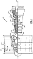
- FIG. 1 schematically illustrates a gas turbine engine 20.
- the gas turbine engine 20 is disclosed herein as a two-spool turbofan that generally incorporates a fan section 22, a compressor section 24, a combustor section 26 and a turbine section 28.
- Alternative engines might include an augmentor section (not shown) among other systems or features.
- the fan section 22 drives air along a bypass flow path B in a bypass duct defined within a nacelle 15, while the compressor section 24 drives air along a core flow path C for compression and communication into the combustor section 26 then expansion through the turbine section 28.
- the exemplary engine 20 generally includes a low speed spool 30 and a high speed spool 32 mounted for rotation about an engine central longitudinal axis A relative to an engine static structure 36 via several bearing systems 38. It should be understood that various bearing systems 38 at various locations may alternatively or additionally be provided, and the location of bearing systems 38 may be varied as appropriate to the application.
- the low speed spool 30 generally includes an inner shaft 40 that interconnects a fan 42, a first (or low) pressure compressor 44 and a first (or low) pressure turbine 46.
- the inner shaft 40 is connected to the fan 42 through a speed change mechanism, which in exemplary gas turbine engine 20 is illustrated as a geared architecture 48 to drive the fan 42 at a lower speed than the low speed spool 30.
- the high speed spool 32 includes an outer shaft 50 that interconnects a second (or high) pressure compressor 52 and a second (or high) pressure turbine 54.
- a combustor 56 is arranged in exemplary gas turbine 20 between the high pressure compressor 52 and the high pressure turbine 54.
- a mid-turbine frame 57 of the engine static structure 36 is arranged generally between the high pressure turbine 54 and the low pressure turbine 46.
- the mid-turbine frame 57 further supports bearing systems 38 in the turbine section 28.
- the inner shaft 40 and the outer shaft 50 are concentric and rotate via bearing systems 38 about the engine central longitudinal axis A which is collinear with their longitudinal axes.
- the core airflow is compressed by the low pressure compressor 44 then the high pressure compressor 52, mixed and burned with fuel in the combustor 56, then expanded over the high pressure turbine 54 and low pressure turbine 46.
- the mid-turbine frame 57 includes airfoils 59 which are in the core flow path C.
- the turbines 46, 54 rotationally drive the respective low speed spool 30 and high speed spool 32 in response to the expansion.
- gear system 48 may be located aft of combustor section 26 or even aft of turbine section 28, and fan section 22 may be positioned forward or aft of the location of gear system 48.
- the engine 20 in one example is a high-bypass geared aircraft engine.
- the engine 20 bypass ratio is greater than about six (6), with an example embodiment being greater than about ten (10)
- the geared architecture 48 is an epicyclic gear train, such as a planetary gear system or other gear system, with a gear reduction ratio of greater than about 2.3
- the low pressure turbine 46 has a pressure ratio that is greater than about five.
- the engine 20 bypass ratio is greater than about ten (10:1)
- the fan diameter is significantly larger than that of the low pressure compressor 44
- the low pressure turbine 46 has a pressure ratio that is greater than about five 5:1.
- Low pressure turbine 46 pressure ratio is pressure measured prior to inlet of low pressure turbine 46 as related to the pressure at the outlet of the low pressure turbine 46 prior to an exhaust nozzle.
- the geared architecture 48 may be an epicycle gear train, such as a planetary gear system or other gear system, with a gear reduction ratio of greater than about 2.3:1. It should be understood, however, that the above parameters are only exemplary of one embodiment of a geared architecture engine and that the present invention is applicable to other gas turbine engines including direct drive turbofans.
- the fan section 22 of the engine 20 is designed for a particular flight condition- typically cruise at about 0.8 Mach and about 35,000 feet (10,668 m).
- "Low fan pressure ratio” is the pressure ratio across the fan blade alone, without a Fan Exit Guide Vane (“FEGV”) system.
- the low fan pressure ratio as disclosed herein according to one non-limiting embodiment is less than about 1.45.
- the "Low corrected fan tip speed" as disclosed herein according to one non-limiting embodiment is less than about 1150 ft / second (350.5 m/s).
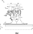
- Figure 2 illustrates a section 60 of a gas turbine engine.
- the section 60 is a portion of a high pressure turbine, such as the high pressure turbine 54. While illustrated relative to a high pressure turbine, it should be understood that this disclosure extends to other engine sections.
- the section 60 includes a first stage 62 and a second stage 64.
- the first stage 62 includes an array of first stator vanes 66 which prepare a core airflow (i.e., the flow within core flow path C) for expansion over an array of first rotor blades 68.
- the second stage 64 includes an array of second stator vanes 70, which prepare the core airflow for expansion over an array of second rotor blades 72.
- the first rotor blades 68 are rotatably attached to a first rotor disk 74 and, likewise, the second rotor blades 72 are attached to a second rotor disk 76.
- the first and second rotor disks 74, 76 are configured to rotate the high speed spool 32 about the engine central longitudinal axis A.
- An example segmented seal 78 is provided axially between the first rotor disk 74 and the second rotor disk 76, and radially inward (in radial direction Z, which is normal to the engine central longitudinal axis A) of the second stator vanes 70.
- the example segmented seal 78 includes a plurality of segments arranged circumferentially relative to one another, as illustrated in Figure 3 .
- the segmented seal 78 may include a plurality of arcuate seal segments 78A-78G which, when arranged to circumferentially adjacent one another in the circumferential direction Y, form a hoop about the engine central longitudinal axis A.
- the interfaces I 1 -I 7 may include at least one of a shiplap joint and/or a feather seal to provide a mechanical connection between adjacent seal segments 78A-78G, as well as increased sealing to prevent leakage between the interfaces I 1 -I- 7 .
- the seal segments 78A-78G may move (e.g., from thermal expansion, vibration, stresses, etc.) relative to one another during operation of the engine 20. This relative movement reduces stresses that may result from operation of the engine 20, especially when compared to seals that are integrally formed as a single, full hoop about an engine's central axis. While seven seal segments 78A-78G are illustrated in Figure 3 , the segmented seal 78 may include any number of segments.
- Figure 4 illustrates the detail of the segmented seal 78.
- each of the seal segments 78A-78G includes the structure illustrated in Figure 4 .
- the segmented seal 78 includes a radially outer surface 80, and a radially inner surface 82 spaced-apart from the radially outer surface 80 in the radial direction Z.
- the segmented seal 78 further includes a fore surface 84, and an aft surface 86 axially spaced-apart from the fore surface 84.
- the segmented seal 78 further includes an interior brace 88 inclined at non-zero angle, relative to the radial direction Z, between the radially outer surface 80 and the aft surface 86.
- segmented seal 78 does not require a brace in all examples.
- the segmented seal 78 could additionally, or alternatively, include other braces extending in various directions within the interior of the segmented seal 78.
- the radially outer surface 80 supports a plurality of knife edge seals 90A-90D.
- the knife edge seals 90A-90D extend radially outward from the outer surface 80 toward a corresponding abradable land 92A-92D.
- the lands 92A-92D are supported by the inner platforms 94 of the second stator vanes 70.
- the lands 92A-92D in one example may be a honeycomb structure, as is known in the art.
- the knife edge seals 90A-90D and the abradable lands 92A-92D define a labyrinth seal 96, which resists a leakage flow L of the core airflow around the second stator vanes 70.
- radially outer surface 80 continuously extends between the fore surface 84 and the aft surface 86.
- the fore surface 84 directly abuts an aft surface 74A the first rotor disk 74.
- each of the fore surface 84 and the aft surface 74A are substantially planar, and extend generally in the radial direction Z.
- the aft surface 86 similarly abuts a fore surface 76F of the second rotor disk 76.
- ring seals 98A, 98B may be provided in grooves 100A, 100B between the surfaces 84 and 74A, and the surfaces 86 and 76F to increase sealing at the respective interfaces.
- segmented seal 78 axially spans the distance between the first rotor disk 74 and the second rotor disk 76, which provides an increased level of sealing between the core flow path C and the first and second rotor disks 74, 76.
- the labyrinth seal fail, a substantial portion of the relatively hot leakage flow L would pass back into the core flow path C, rather than being directed radially inward toward the first and second rotor disks 74, 76.
- the segmented seal 78 is further supported relative to the first and second rotor disks 74, 76 by ledges 102A, 102B projecting from the radially inner surface 82, which are arranged relative to corresponding lips 104A, 104B of the first and second rotor disks 74, 76.
- One or more of the lip-ledge interfaces may provide an anti-rotation feature 105, such as a lug projecting into a slot, to prevent the segmented seal 78 from rotating circumferentially relative to the first and second rotor disks 74, 76.
- an anti-rotation feature 105 such as a lug projecting into a slot
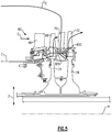
- FIGS 5-6 illustrate two example cooling arrangements.
- a first cooling flow path C 1 extends from a tangential on-board injector (or, TOBI), for example, into the first disk 74, radially outward through the first rotor blades 68 and into the core flow path C.
- a second cooling flow path C 2 is provided from radially outward location, and is sourced from a mid-stage or HPC bleed, as examples.
- the second cooling flow path C 2 flows radially through the second stator vanes 70, and exits the second stator vanes 70 adjacent a gap between lands 92B and 92C.
- the second cooling flow path C 2 then moves radially between the knife edge seals 90B, 90C and through a first perforation 106 in the radially outer surface 80 of the segmented seal 78 ( Figure 4 ). Some of the leakage flow L may enter the second cooling flow path C 2 , however the effects of the leakage flow L may be minimal.
- the brace 88 ( Figure 4 ) is substantially solid in this example, and turns the fluid within the second cooling flow path C 2 axially toward a second perforation 108 in the aft surface 86. The second cooling flow path C 2 then radially turns to provide a flow of fluid to cool the second rotor blades 72.
- a first flow path C 1 is directed toward the first disk 74 from a TOBI.
- the first flow path C 1 splits into a first portion C 1-A , which is directed radially outward to cool the first rotor blades 68, and a second portion C 1-B , which is directed axially through the first rotor disk 74.
- the second portion C 1-B then passes axially through the segmented seal 78.
- the fore surface 84, the brace 88, and the aft surface 86 of the segmented seal would include perforations, whereas the outer surface 80 and the inner surface 82 would be solid.
- the second stator vanes 70 may be cooled with a second flow path C 2 , which would flow through the second stator vanes 70 and exit out a trailing edge in the second stator vanes 70 into the core flow path C.
Landscapes
- Engineering & Computer Science (AREA)
- Mechanical Engineering (AREA)
- General Engineering & Computer Science (AREA)
- Turbine Rotor Nozzle Sealing (AREA)
Claims (11)
- Gasturbinenmotor (20), der Folgendes umfasst:eine erste Rotorscheibe (74);eine zweite Rotorscheibe (76); undeine in Umfangsrichtung segmentierte Dichtung (78), die in die erste Rotorscheibe (74) und die zweite Rotorscheibe (76) eingreift und eine radial äußere Fläche (80), die sich zwischen einer vorderen Fläche (84) der segmentierten Dichtung (78) und einer hinteren Fläche (86) der segmentierten Dichtung (78) erstreckt, beinhaltet,dadurch gekennzeichnet, dass:die vordere Fläche (84) direkt an eine hintere Fläche (74A) der ersten Scheibe (74) anliegt;die hintere Fläche (86) direkt an eine vordere Fläche (76A) der zweiten Scheibe (76) anliegt;die hintere Fläche (86) der segmentierten Dichtung (78) und die radial äußere Fläche (80) der segmentierten Dichtung (78) Perforationen (106, 108) beinhalten, um zuzulassen, dass Kühlfluid durch die radial äußere Fläche (80) der segmentierten Dichtung (78) und die hintere Fläche (86) der segmentierten Dichtung (78) und durch das Innere der segmentierten Dichtung (78) fließt; undeine radial innere Fläche (82) der segmentierten Dichtung (78), die von der äußeren Fläche (80) der segmentierten Dichtung (78) radial nach innen beabstandet ist und sich zwischen der vorderen Fläche (84) der segmentierten Dichtung (78) und der hinteren Fläche (86) der segmentierten Dichtung (78) erstreckt, und die vordere Fläche (84) der segmentierten Dichtung (78) im Wesentlichen massiv sind.
- Gasturbinenmotor nach Anspruch 1, wobei die segmentierte Dichtung (78) eine Vielzahl von bogenförmigen Segmenten (78A-78G) beinhaltet, die in Umfangsrichtung nebeneinander angeordnet sind, um einen Ring um eine Mittellängsachse des Motors zu bilden.
- Gasturbinenmotor nach Anspruch 2, wobei mindestens eines von einer überlappenden Verbindung und einem Dichtstreifen zwischen benachbarten Segmenten (78A-78G) bereitgestellt ist.
- Gasturbinenmotor nach einem der vorstehenden Ansprüche, beinhaltend eine erste Ringdichtung (98A), die zwischen der vorderen Fläche (84) der segmentierten Dichtung (78) und der ersten Scheibe (74) bereitgestellt ist, und eine zweite Ringdichtung (98B), die zwischen der hinteren Fläche (86) der segmentierten Dichtung (78) und der zweiten Scheibe (76) bereitgestellt ist.
- Gasturbinenmotor nach einem der vorstehenden Ansprüche, wobei die radial innere Fläche (82) der segmentierten Dichtung eine erste Leiste (102A), die nach vorne vorsteht, und eine zweite Leiste (102B), die von der radial inneren Fläche (82) nach hinten vorsteht, bereitstellt, wobei die erste und zweite Leiste (102A, 102B) eine jeweilige hintere und vordere Lippe (104A, 104B) berühren, die in der ersten Rotorscheibe (74) bzw. der zweiten Rotorscheibe (76) gebildet sind.
- Gasturbinenmotor nach einem der vorstehenden Ansprüche, wobei eine Vielzahl von Schneidendichtungen (90A-90D) auf der radial äußeren Fläche (80) gelagert ist.
- Gasturbinenmotor nach Anspruch 6, beinhaltend eine Vielzahl von Statorschaufeln (70), die zwischen der ersten Rotorscheibe (74) und der zweiten Rotorscheibe (76) bereitgestellt ist, wobei die Schneidendichtungen (90A-90D) dazu konfiguriert sind, gegen einen abtragbaren Steg (92A-92D), der auf einer inneren Plattform (94) der Statorschaufeln (70) gelagert ist, abzudichten.
- Gasturbinenmotor nach einem der vorstehenden Ansprüche, beinhaltend eine Strebe (88), die sich zwischen der radial äußeren Fläche (80) der segmentierten Dichtung (78) und der hinteren Fläche (86) der segmentierten Dichtung (78) erstreckt, wobei die Strebe (88) im Wesentlichen massiv ist, sodass die Strebe (88) dazu konfiguriert ist, einen Fluidfluss umzudrehen, wenn das Fluid zwischen der Perforation in der radial äußeren Fläche (80) der segmentierten Dichtung (78) und der Perforation in der hinteren Fläche (86) der segmentierten Dichtung (78) strömt.
- Gasturbinenmotor nach einem der vorstehenden Ansprüche, beinhaltend ein Drehsicherungsmerkmal (105) zwischen der segmentierten Dichtung (78) und einer von der ersten Scheibe (74) und der zweiten Scheibe (76), wobei das Drehsicherungsmerkmal (105) eine Drehung der segmentierten Dichtung (78) in Umfangsrichtung in Bezug auf die erste und zweite Rotorscheibe (74, 76) verhindert.
- Gasturbinenmotor nach Anspruch 9, wobei das Drehsicherungsmerkmal (105) eine in einem Schlitz aufgenommenen Nase beinhaltet.
- Gasturbinenmotor nach einem der vorstehenden Ansprüche, wobei die vordere Fläche (84) der segmentierten Dichtung (78) und die hintere Fläche (86) der segmentierten Dichtung (78) ebenflächig sind und sich in einer radialen Richtung (Z) erstrecken.
Applications Claiming Priority (2)
| Application Number | Priority Date | Filing Date | Title |
|---|---|---|---|
| US201361902555P | 2013-11-11 | 2013-11-11 | |
| PCT/US2014/064956 WO2015119687A2 (en) | 2013-11-11 | 2014-11-11 | Segmented seal for gas turbine engine |
Publications (3)
| Publication Number | Publication Date |
|---|---|
| EP3068997A2 EP3068997A2 (de) | 2016-09-21 |
| EP3068997A4 EP3068997A4 (de) | 2017-07-05 |
| EP3068997B1 true EP3068997B1 (de) | 2021-12-29 |
Family
ID=53778589
Family Applications (1)
| Application Number | Title | Priority Date | Filing Date |
|---|---|---|---|
| EP14881671.3A Active EP3068997B1 (de) | 2013-11-11 | 2014-11-11 | Segmentierte dichtung für gasturbinenmotor |
Country Status (3)
| Country | Link |
|---|---|
| US (1) | US10287905B2 (de) |
| EP (1) | EP3068997B1 (de) |
| WO (1) | WO2015119687A2 (de) |
Families Citing this family (5)
| Publication number | Priority date | Publication date | Assignee | Title |
|---|---|---|---|---|
| US10233840B2 (en) * | 2014-04-25 | 2019-03-19 | United Technologies Corporation | Compressor injector apparatus and system |
| US9970299B2 (en) * | 2015-09-16 | 2018-05-15 | General Electric Company | Mixing chambers for turbine wheel space cooling |
| FR3070715B1 (fr) * | 2017-09-06 | 2021-07-30 | Safran Aircraft Engines | Languette d'etancheite inter secteurs de turbomachine d'aeronef |
| EP3540180A1 (de) * | 2018-03-14 | 2019-09-18 | General Electric Company | Zwischenstufen-hohlraumspülkanäle |
| US11415016B2 (en) * | 2019-11-11 | 2022-08-16 | Rolls-Royce Plc | Turbine section assembly with ceramic matrix composite components and interstage sealing features |
Family Cites Families (37)
| Publication number | Priority date | Publication date | Assignee | Title |
|---|---|---|---|---|
| US3056579A (en) * | 1959-04-13 | 1962-10-02 | Gen Electric | Rotor construction |
| US3733146A (en) * | 1971-04-07 | 1973-05-15 | United Aircraft Corp | Gas seal rotatable support structure |
| US4094673A (en) | 1974-02-28 | 1978-06-13 | Brunswick Corporation | Abradable seal material and composition thereof |
| US4139376A (en) | 1974-02-28 | 1979-02-13 | Brunswick Corporation | Abradable seal material and composition thereof |
| US3918832A (en) | 1974-07-29 | 1975-11-11 | United Technologies Corp | Stator construction for an axial flow compressor |
| US4155755A (en) | 1977-09-21 | 1979-05-22 | Union Carbide Corporation | Oxidation resistant porous abradable seal member for high temperature service |
| US4251272A (en) | 1978-12-26 | 1981-02-17 | Union Carbide Corporation | Oxidation resistant porous abradable seal member for high temperature service |
| US4551064A (en) | 1982-03-05 | 1985-11-05 | Rolls-Royce Limited | Turbine shroud and turbine shroud assembly |
| GB2117843B (en) * | 1982-04-01 | 1985-11-06 | Rolls Royce | Compressor shrouds |
| US4659285A (en) | 1984-07-23 | 1987-04-21 | United Technologies Corporation | Turbine cover-seal assembly |
| EP0187612B1 (de) | 1984-12-24 | 1990-09-12 | United Technologies Corporation | Abschleifbare Dichtung mit besonderem Erosionswiderstand |
| US4721433A (en) | 1985-12-19 | 1988-01-26 | United Technologies Corporation | Coolable stator structure for a gas turbine engine |
| US4897021A (en) | 1988-06-02 | 1990-01-30 | United Technologies Corporation | Stator vane asssembly for an axial flow rotary machine |
| US4884950A (en) * | 1988-09-06 | 1989-12-05 | United Technologies Corporation | Segmented interstage seal assembly |
| US4936745A (en) | 1988-12-16 | 1990-06-26 | United Technologies Corporation | Thin abradable ceramic air seal |
| US5017402A (en) | 1988-12-21 | 1991-05-21 | United Technologies Corporation | Method of coating abradable seal assembly |
| US5536022A (en) | 1990-08-24 | 1996-07-16 | United Technologies Corporation | Plasma sprayed abradable seals for gas turbine engines |
| US5350557A (en) | 1991-09-23 | 1994-09-27 | Technetics Corp. | Impermeable, abradable seal and method for the production thereof |
| US5655701A (en) | 1995-07-10 | 1997-08-12 | United Technologies Corporation | Method for repairing an abradable seal |
| GB2307520B (en) * | 1995-11-14 | 1999-07-07 | Rolls Royce Plc | A gas turbine engine |
| US5785492A (en) | 1997-03-24 | 1998-07-28 | United Technologies Corporation | Method and apparatus for sealing a gas turbine stator vane assembly |
| US6146091A (en) * | 1998-03-03 | 2000-11-14 | Mitsubishi Heavy Industries, Ltd. | Gas turbine cooling structure |
| US6089825A (en) | 1998-12-18 | 2000-07-18 | United Technologies Corporation | Abradable seal having improved properties and method of producing seal |
| US6352264B1 (en) | 1999-12-17 | 2002-03-05 | United Technologies Corporation | Abradable seal having improved properties |
| US6899339B2 (en) | 2001-08-30 | 2005-05-31 | United Technologies Corporation | Abradable seal having improved durability |
| US7032904B2 (en) | 2003-08-13 | 2006-04-25 | United Technologies Corporation | Inner air seal anti-rotation device |
| US7334983B2 (en) * | 2005-10-27 | 2008-02-26 | United Technologies Corporation | Integrated bladed fluid seal |
| GB0611031D0 (en) | 2006-06-06 | 2006-07-12 | Rolls Royce Plc | An aerofoil stage and a seal for use therein |
| US20080260523A1 (en) | 2007-04-18 | 2008-10-23 | Ioannis Alvanos | Gas turbine engine with integrated abradable seal |
| US20090238683A1 (en) | 2008-03-24 | 2009-09-24 | United Technologies Corporation | Vane with integral inner air seal |
| US8221062B2 (en) * | 2009-01-14 | 2012-07-17 | General Electric Company | Device and system for reducing secondary air flow in a gas turbine |
| JP5388954B2 (ja) * | 2010-06-14 | 2014-01-15 | キヤノン株式会社 | 発光素子及びその製造方法 |
| US8845284B2 (en) * | 2010-07-02 | 2014-09-30 | General Electric Company | Apparatus and system for sealing a turbine rotor |
| US20120321437A1 (en) * | 2011-06-17 | 2012-12-20 | General Electric Company | Turbine seal system |
| US20130177383A1 (en) | 2012-01-05 | 2013-07-11 | General Electric Company | Device and method for sealing a gas path in a turbine |
| US8979486B2 (en) | 2012-01-10 | 2015-03-17 | United Technologies Corporation | Intersegment spring “T” seal |
| US10138751B2 (en) | 2012-12-19 | 2018-11-27 | United Technologies Corporation | Segmented seal for a gas turbine engine |
-
2014
- 2014-11-11 EP EP14881671.3A patent/EP3068997B1/de active Active
- 2014-11-11 US US15/036,019 patent/US10287905B2/en active Active
- 2014-11-11 WO PCT/US2014/064956 patent/WO2015119687A2/en not_active Ceased
Also Published As
| Publication number | Publication date |
|---|---|
| US20160290149A1 (en) | 2016-10-06 |
| WO2015119687A2 (en) | 2015-08-13 |
| EP3068997A4 (de) | 2017-07-05 |
| EP3068997A2 (de) | 2016-09-21 |
| US10287905B2 (en) | 2019-05-14 |
| WO2015119687A3 (en) | 2015-10-29 |
Similar Documents
| Publication | Publication Date | Title |
|---|---|---|
| US10072517B2 (en) | Gas turbine engine component having variable width feather seal slot | |
| US10329931B2 (en) | Stator assembly for a gas turbine engine | |
| EP2998520B1 (de) | Zwischenstufige abdichtung für gasturbinentriebwerk | |
| US10436054B2 (en) | Blade outer air seal for a gas turbine engine | |
| EP3093445B1 (de) | Gasturbinen-leitschaufel und herstellungsverfahren | |
| US10138751B2 (en) | Segmented seal for a gas turbine engine | |
| EP2971585B1 (de) | Schienendichtung für eine gasturbinenschaufel | |
| US20160003084A1 (en) | Thermally conformable liner for reducing system level fan blade out loads | |
| US10287905B2 (en) | Segmented seal for gas turbine engine | |
| EP3498978B1 (de) | Gasturbinenleitschaufel mit befestigungshaken | |
| EP2995778B1 (de) | Verfahren und anordnung zur verminderung sekundärer wärme in einem gasturbinenmotor | |
| EP3000966B1 (de) | Verfahren und anordnung zur verminderung sekundärer wärme in einem gasturbinenmotor | |
| US10794207B2 (en) | Gas turbine engine airfoil component platform seal cooling | |
| EP3620611B1 (de) | Einheitlicher boas-träger und schaufelplattform | |
| EP3597870B1 (de) | Gasturbine | |
| EP2986823A2 (de) | Kantengeometrie für eine gasturbinenmotorschaufelplattform |
Legal Events
| Date | Code | Title | Description |
|---|---|---|---|
| PUAI | Public reference made under article 153(3) epc to a published international application that has entered the european phase |
Free format text: ORIGINAL CODE: 0009012 |
|
| 17P | Request for examination filed |
Effective date: 20160610 |
|
| AK | Designated contracting states |
Kind code of ref document: A2 Designated state(s): AL AT BE BG CH CY CZ DE DK EE ES FI FR GB GR HR HU IE IS IT LI LT LU LV MC MK MT NL NO PL PT RO RS SE SI SK SM TR |
|
| AX | Request for extension of the european patent |
Extension state: BA ME |
|
| RAP1 | Party data changed (applicant data changed or rights of an application transferred) |
Owner name: UNITED TECHNOLOGIES CORPORATION |
|
| DAX | Request for extension of the european patent (deleted) | ||
| REG | Reference to a national code |
Ref country code: DE Ref legal event code: R079 Ref document number: 602014081956 Country of ref document: DE Free format text: PREVIOUS MAIN CLASS: F02C0007280000 Ipc: F01D0011000000 |
|
| A4 | Supplementary search report drawn up and despatched |
Effective date: 20170608 |
|
| RIC1 | Information provided on ipc code assigned before grant |
Ipc: F01D 11/00 20060101AFI20170601BHEP Ipc: F01D 5/08 20060101ALI20170601BHEP |
|
| STAA | Information on the status of an ep patent application or granted ep patent |
Free format text: STATUS: EXAMINATION IS IN PROGRESS |
|
| 17Q | First examination report despatched |
Effective date: 20200610 |
|
| RAP1 | Party data changed (applicant data changed or rights of an application transferred) |
Owner name: RAYTHEON TECHNOLOGIES CORPORATION |
|
| GRAP | Despatch of communication of intention to grant a patent |
Free format text: ORIGINAL CODE: EPIDOSNIGR1 |
|
| STAA | Information on the status of an ep patent application or granted ep patent |
Free format text: STATUS: GRANT OF PATENT IS INTENDED |
|
| INTG | Intention to grant announced |
Effective date: 20210701 |
|
| GRAS | Grant fee paid |
Free format text: ORIGINAL CODE: EPIDOSNIGR3 |
|
| GRAA | (expected) grant |
Free format text: ORIGINAL CODE: 0009210 |
|
| STAA | Information on the status of an ep patent application or granted ep patent |
Free format text: STATUS: THE PATENT HAS BEEN GRANTED |
|
| AK | Designated contracting states |
Kind code of ref document: B1 Designated state(s): AL AT BE BG CH CY CZ DE DK EE ES FI FR GB GR HR HU IE IS IT LI LT LU LV MC MK MT NL NO PL PT RO RS SE SI SK SM TR |
|
| REG | Reference to a national code |
Ref country code: GB Ref legal event code: FG4D |
|
| REG | Reference to a national code |
Ref country code: CH Ref legal event code: EP |
|
| REG | Reference to a national code |
Ref country code: AT Ref legal event code: REF Ref document number: 1458821 Country of ref document: AT Kind code of ref document: T Effective date: 20220115 |
|
| REG | Reference to a national code |
Ref country code: IE Ref legal event code: FG4D |
|
| REG | Reference to a national code |
Ref country code: DE Ref legal event code: R096 Ref document number: 602014081956 Country of ref document: DE |
|
| REG | Reference to a national code |
Ref country code: LT Ref legal event code: MG9D |
|
| PG25 | Lapsed in a contracting state [announced via postgrant information from national office to epo] |
Ref country code: RS Free format text: LAPSE BECAUSE OF FAILURE TO SUBMIT A TRANSLATION OF THE DESCRIPTION OR TO PAY THE FEE WITHIN THE PRESCRIBED TIME-LIMIT Effective date: 20211229 Ref country code: LT Free format text: LAPSE BECAUSE OF FAILURE TO SUBMIT A TRANSLATION OF THE DESCRIPTION OR TO PAY THE FEE WITHIN THE PRESCRIBED TIME-LIMIT Effective date: 20211229 Ref country code: FI Free format text: LAPSE BECAUSE OF FAILURE TO SUBMIT A TRANSLATION OF THE DESCRIPTION OR TO PAY THE FEE WITHIN THE PRESCRIBED TIME-LIMIT Effective date: 20211229 Ref country code: BG Free format text: LAPSE BECAUSE OF FAILURE TO SUBMIT A TRANSLATION OF THE DESCRIPTION OR TO PAY THE FEE WITHIN THE PRESCRIBED TIME-LIMIT Effective date: 20220329 |
|
| REG | Reference to a national code |
Ref country code: NL Ref legal event code: MP Effective date: 20211229 |
|
| REG | Reference to a national code |
Ref country code: AT Ref legal event code: MK05 Ref document number: 1458821 Country of ref document: AT Kind code of ref document: T Effective date: 20211229 |
|
| PG25 | Lapsed in a contracting state [announced via postgrant information from national office to epo] |
Ref country code: SE Free format text: LAPSE BECAUSE OF FAILURE TO SUBMIT A TRANSLATION OF THE DESCRIPTION OR TO PAY THE FEE WITHIN THE PRESCRIBED TIME-LIMIT Effective date: 20211229 Ref country code: NO Free format text: LAPSE BECAUSE OF FAILURE TO SUBMIT A TRANSLATION OF THE DESCRIPTION OR TO PAY THE FEE WITHIN THE PRESCRIBED TIME-LIMIT Effective date: 20220329 Ref country code: LV Free format text: LAPSE BECAUSE OF FAILURE TO SUBMIT A TRANSLATION OF THE DESCRIPTION OR TO PAY THE FEE WITHIN THE PRESCRIBED TIME-LIMIT Effective date: 20211229 Ref country code: HR Free format text: LAPSE BECAUSE OF FAILURE TO SUBMIT A TRANSLATION OF THE DESCRIPTION OR TO PAY THE FEE WITHIN THE PRESCRIBED TIME-LIMIT Effective date: 20211229 Ref country code: GR Free format text: LAPSE BECAUSE OF FAILURE TO SUBMIT A TRANSLATION OF THE DESCRIPTION OR TO PAY THE FEE WITHIN THE PRESCRIBED TIME-LIMIT Effective date: 20220330 |
|
| PG25 | Lapsed in a contracting state [announced via postgrant information from national office to epo] |
Ref country code: NL Free format text: LAPSE BECAUSE OF FAILURE TO SUBMIT A TRANSLATION OF THE DESCRIPTION OR TO PAY THE FEE WITHIN THE PRESCRIBED TIME-LIMIT Effective date: 20211229 |
|
| PG25 | Lapsed in a contracting state [announced via postgrant information from national office to epo] |
Ref country code: SM Free format text: LAPSE BECAUSE OF FAILURE TO SUBMIT A TRANSLATION OF THE DESCRIPTION OR TO PAY THE FEE WITHIN THE PRESCRIBED TIME-LIMIT Effective date: 20211229 Ref country code: SK Free format text: LAPSE BECAUSE OF FAILURE TO SUBMIT A TRANSLATION OF THE DESCRIPTION OR TO PAY THE FEE WITHIN THE PRESCRIBED TIME-LIMIT Effective date: 20211229 Ref country code: RO Free format text: LAPSE BECAUSE OF FAILURE TO SUBMIT A TRANSLATION OF THE DESCRIPTION OR TO PAY THE FEE WITHIN THE PRESCRIBED TIME-LIMIT Effective date: 20211229 Ref country code: PT Free format text: LAPSE BECAUSE OF FAILURE TO SUBMIT A TRANSLATION OF THE DESCRIPTION OR TO PAY THE FEE WITHIN THE PRESCRIBED TIME-LIMIT Effective date: 20220429 Ref country code: ES Free format text: LAPSE BECAUSE OF FAILURE TO SUBMIT A TRANSLATION OF THE DESCRIPTION OR TO PAY THE FEE WITHIN THE PRESCRIBED TIME-LIMIT Effective date: 20211229 Ref country code: EE Free format text: LAPSE BECAUSE OF FAILURE TO SUBMIT A TRANSLATION OF THE DESCRIPTION OR TO PAY THE FEE WITHIN THE PRESCRIBED TIME-LIMIT Effective date: 20211229 Ref country code: CZ Free format text: LAPSE BECAUSE OF FAILURE TO SUBMIT A TRANSLATION OF THE DESCRIPTION OR TO PAY THE FEE WITHIN THE PRESCRIBED TIME-LIMIT Effective date: 20211229 |
|
| PG25 | Lapsed in a contracting state [announced via postgrant information from national office to epo] |
Ref country code: PL Free format text: LAPSE BECAUSE OF FAILURE TO SUBMIT A TRANSLATION OF THE DESCRIPTION OR TO PAY THE FEE WITHIN THE PRESCRIBED TIME-LIMIT Effective date: 20211229 Ref country code: AT Free format text: LAPSE BECAUSE OF FAILURE TO SUBMIT A TRANSLATION OF THE DESCRIPTION OR TO PAY THE FEE WITHIN THE PRESCRIBED TIME-LIMIT Effective date: 20211229 |
|
| PG25 | Lapsed in a contracting state [announced via postgrant information from national office to epo] |
Ref country code: IS Free format text: LAPSE BECAUSE OF FAILURE TO SUBMIT A TRANSLATION OF THE DESCRIPTION OR TO PAY THE FEE WITHIN THE PRESCRIBED TIME-LIMIT Effective date: 20220429 |
|
| REG | Reference to a national code |
Ref country code: DE Ref legal event code: R097 Ref document number: 602014081956 Country of ref document: DE |
|
| PG25 | Lapsed in a contracting state [announced via postgrant information from national office to epo] |
Ref country code: DK Free format text: LAPSE BECAUSE OF FAILURE TO SUBMIT A TRANSLATION OF THE DESCRIPTION OR TO PAY THE FEE WITHIN THE PRESCRIBED TIME-LIMIT Effective date: 20211229 Ref country code: AL Free format text: LAPSE BECAUSE OF FAILURE TO SUBMIT A TRANSLATION OF THE DESCRIPTION OR TO PAY THE FEE WITHIN THE PRESCRIBED TIME-LIMIT Effective date: 20211229 |
|
| PLBE | No opposition filed within time limit |
Free format text: ORIGINAL CODE: 0009261 |
|
| STAA | Information on the status of an ep patent application or granted ep patent |
Free format text: STATUS: NO OPPOSITION FILED WITHIN TIME LIMIT |
|
| 26N | No opposition filed |
Effective date: 20220930 |
|
| PG25 | Lapsed in a contracting state [announced via postgrant information from national office to epo] |
Ref country code: SI Free format text: LAPSE BECAUSE OF FAILURE TO SUBMIT A TRANSLATION OF THE DESCRIPTION OR TO PAY THE FEE WITHIN THE PRESCRIBED TIME-LIMIT Effective date: 20211229 |
|
| PG25 | Lapsed in a contracting state [announced via postgrant information from national office to epo] |
Ref country code: IT Free format text: LAPSE BECAUSE OF FAILURE TO SUBMIT A TRANSLATION OF THE DESCRIPTION OR TO PAY THE FEE WITHIN THE PRESCRIBED TIME-LIMIT Effective date: 20211229 |
|
| P01 | Opt-out of the competence of the unified patent court (upc) registered |
Effective date: 20230520 |
|
| PG25 | Lapsed in a contracting state [announced via postgrant information from national office to epo] |
Ref country code: MC Free format text: LAPSE BECAUSE OF FAILURE TO SUBMIT A TRANSLATION OF THE DESCRIPTION OR TO PAY THE FEE WITHIN THE PRESCRIBED TIME-LIMIT Effective date: 20211229 |
|
| REG | Reference to a national code |
Ref country code: CH Ref legal event code: PL |
|
| REG | Reference to a national code |
Ref country code: BE Ref legal event code: MM Effective date: 20221130 |
|
| PG25 | Lapsed in a contracting state [announced via postgrant information from national office to epo] |
Ref country code: LI Free format text: LAPSE BECAUSE OF NON-PAYMENT OF DUE FEES Effective date: 20221130 Ref country code: CH Free format text: LAPSE BECAUSE OF NON-PAYMENT OF DUE FEES Effective date: 20221130 |
|
| PG25 | Lapsed in a contracting state [announced via postgrant information from national office to epo] |
Ref country code: LU Free format text: LAPSE BECAUSE OF NON-PAYMENT OF DUE FEES Effective date: 20221111 |
|
| PG25 | Lapsed in a contracting state [announced via postgrant information from national office to epo] |
Ref country code: IE Free format text: LAPSE BECAUSE OF NON-PAYMENT OF DUE FEES Effective date: 20221111 |
|
| PG25 | Lapsed in a contracting state [announced via postgrant information from national office to epo] |
Ref country code: BE Free format text: LAPSE BECAUSE OF NON-PAYMENT OF DUE FEES Effective date: 20221130 |
|
| PG25 | Lapsed in a contracting state [announced via postgrant information from national office to epo] |
Ref country code: HU Free format text: LAPSE BECAUSE OF FAILURE TO SUBMIT A TRANSLATION OF THE DESCRIPTION OR TO PAY THE FEE WITHIN THE PRESCRIBED TIME-LIMIT; INVALID AB INITIO Effective date: 20141111 |
|
| PG25 | Lapsed in a contracting state [announced via postgrant information from national office to epo] |
Ref country code: CY Free format text: LAPSE BECAUSE OF FAILURE TO SUBMIT A TRANSLATION OF THE DESCRIPTION OR TO PAY THE FEE WITHIN THE PRESCRIBED TIME-LIMIT Effective date: 20211229 |
|
| PG25 | Lapsed in a contracting state [announced via postgrant information from national office to epo] |
Ref country code: MK Free format text: LAPSE BECAUSE OF FAILURE TO SUBMIT A TRANSLATION OF THE DESCRIPTION OR TO PAY THE FEE WITHIN THE PRESCRIBED TIME-LIMIT Effective date: 20211229 |
|
| PG25 | Lapsed in a contracting state [announced via postgrant information from national office to epo] |
Ref country code: TR Free format text: LAPSE BECAUSE OF FAILURE TO SUBMIT A TRANSLATION OF THE DESCRIPTION OR TO PAY THE FEE WITHIN THE PRESCRIBED TIME-LIMIT Effective date: 20211229 |
|
| PG25 | Lapsed in a contracting state [announced via postgrant information from national office to epo] |
Ref country code: MT Free format text: LAPSE BECAUSE OF FAILURE TO SUBMIT A TRANSLATION OF THE DESCRIPTION OR TO PAY THE FEE WITHIN THE PRESCRIBED TIME-LIMIT Effective date: 20211229 |
|
| REG | Reference to a national code |
Ref country code: DE Ref legal event code: R081 Ref document number: 602014081956 Country of ref document: DE Owner name: RTX CORPORATION (N.D.GES.D. STAATES DELAWARE),, US Free format text: FORMER OWNER: RAYTHEON TECHNOLOGIES CORPORATION, FARMINGTON, CT, US |
|
| PGFP | Annual fee paid to national office [announced via postgrant information from national office to epo] |
Ref country code: DE Payment date: 20251022 Year of fee payment: 12 |
|
| PGFP | Annual fee paid to national office [announced via postgrant information from national office to epo] |
Ref country code: GB Payment date: 20251023 Year of fee payment: 12 |
|
| PGFP | Annual fee paid to national office [announced via postgrant information from national office to epo] |
Ref country code: FR Payment date: 20251023 Year of fee payment: 12 |