EP3069094B1 - Ensemble auget de collecte d'eau - Google Patents
Ensemble auget de collecte d'eau Download PDFInfo
- Publication number
- EP3069094B1 EP3069094B1 EP14806089.0A EP14806089A EP3069094B1 EP 3069094 B1 EP3069094 B1 EP 3069094B1 EP 14806089 A EP14806089 A EP 14806089A EP 3069094 B1 EP3069094 B1 EP 3069094B1
- Authority
- EP
- European Patent Office
- Prior art keywords
- capture
- liquid
- plate
- trough assembly
- troughs
- Prior art date
- Legal status (The legal status is an assumption and is not a legal conclusion. Google has not performed a legal analysis and makes no representation as to the accuracy of the status listed.)
- Not-in-force
Links
Images


Classifications
-
- F—MECHANICAL ENGINEERING; LIGHTING; HEATING; WEAPONS; BLASTING
- F28—HEAT EXCHANGE IN GENERAL
- F28F—DETAILS OF HEAT-EXCHANGE AND HEAT-TRANSFER APPARATUS, OF GENERAL APPLICATION
- F28F25/00—Component parts of trickle coolers
- F28F25/02—Component parts of trickle coolers for distributing, circulating, and accumulating liquid
- F28F25/04—Distributing or accumulator troughs
-
- B—PERFORMING OPERATIONS; TRANSPORTING
- B01—PHYSICAL OR CHEMICAL PROCESSES OR APPARATUS IN GENERAL
- B01F—MIXING, e.g. DISSOLVING, EMULSIFYING OR DISPERSING
- B01F23/00—Mixing according to the phases to be mixed, e.g. dispersing or emulsifying
- B01F23/20—Mixing gases with liquids
-
- B—PERFORMING OPERATIONS; TRANSPORTING
- B01—PHYSICAL OR CHEMICAL PROCESSES OR APPARATUS IN GENERAL
- B01F—MIXING, e.g. DISSOLVING, EMULSIFYING OR DISPERSING
- B01F23/00—Mixing according to the phases to be mixed, e.g. dispersing or emulsifying
- B01F23/20—Mixing gases with liquids
- B01F23/21—Mixing gases with liquids by introducing liquids into gaseous media
- B01F23/214—Mixing gases with liquids by introducing liquids into gaseous media using a gas-liquid mixing column or tower
-
- B—PERFORMING OPERATIONS; TRANSPORTING
- B01—PHYSICAL OR CHEMICAL PROCESSES OR APPARATUS IN GENERAL
- B01F—MIXING, e.g. DISSOLVING, EMULSIFYING OR DISPERSING
- B01F23/00—Mixing according to the phases to be mixed, e.g. dispersing or emulsifying
- B01F23/20—Mixing gases with liquids
- B01F23/23—Mixing gases with liquids by introducing gases into liquid media, e.g. for producing aerated liquids
- B01F23/232—Mixing gases with liquids by introducing gases into liquid media, e.g. for producing aerated liquids using flow-mixing means for introducing the gases, e.g. baffles
- B01F23/2321—Mixing gases with liquids by introducing gases into liquid media, e.g. for producing aerated liquids using flow-mixing means for introducing the gases, e.g. baffles by moving liquid and gas in counter current
Definitions
- This invention relates to a water collection trough assembly for use in air-cooled heat exchangers such as cooling towers having fill over which water to be cooled flows and heat exchangers having deluged tube bundles such as those in condensers, dephlegmators and the like over which water flows to transfer heat to or from the tubes.
- a liquid collection trough according to the preamble of claim 1 is known e.g. from document DE 2250776 .
- Water collection trough assemblies are used in the heat exchanger industry in counter flow cooling towers to collect and remove water falling from the bottom of a cooling tower fill or from a heat exchanger tube bundle. Forced draught cooling towers require water collection trough assemblies in order to collect water falling from the fill of the cooling tower or other water cooling facility to enable the water to be recycled or disposed of in an effective way.
- Collecting troughs are used in forced draught cooling towers; in cooling towers where the rain zone is eliminated to reduce pumping power; in counter-flow cooling tower fill test facilities; and in deluged evaporative heat exchangers, to collect and remove water dripping from the base of the cooling tower fills or heat exchanger tube bundles while allowing it to pass vertically through them.
- Effective recovery of the water also reduces damage to, and maintenance of, fans and drives which create air flow through a heat exchange facility.
- Some water collection assemblies have multiple parallel troughs extending in one direction beneath the fill of a cooling tower or tube bundle with an upwardly inclined capture plate having its lower edge arranged to feed water falling onto the capture plate into an associated trough.
- the troughs and capture plates are arranged to extend over substantially the entire area beneath the fill or tube bundle, as the case may be, so that all water that drips from the fill or tube bundle falls onto a capture plate or directly into a trough.
- US patent number 4,521,350 describes such an arrangement.
- the difficulty with this arrangement is that water drops falling on the capture plate tend to splash and at least a part of the resultant spray can find its way between the troughs thereby failing to be caught by the trough and capture plate assembly. This has led, in at least some instances, to a second layer of collection troughs and capture plates being located beneath a first one.
- collection trough assemblies may be provided beneath tube bundles in order to collect run-off water and enable recycling of excess deluge water.
- a liquid collection trough assembly comprising a plurality of elongate troughs and associated inclined capture plates wherein each capture plate is arranged to receive liquid contacting same on a front face thereof and direct the liquid into an associated elongate trough, wherein each capture plate has a generally upright deflection plate extending downwards from an upper region thereof on its rear face so as to be capable of receiving liquid droplets contacting it and directing such liquid into or onto an adjacent trough or capture plate, in use, and wherein a top edge region of each capture plate and any superimposed deflection plate is vertical or inwardly curved towards the face of the capture plate in a manner tending to redirect air passing in an inclined direction between adjacent capture plates to a more vertically extending direction.
- troughs and associated inclined capture plates to be spaced apart such that the upper edge of each of the capture plates is located over a lower edge region of an adjacent capture plate to define inclined flow paths for air between the capture plates; for a capture plate to be formed as an upward extension of one wall of the trough, in each case; for the deflection plate to be attached along a top edge of an associated inclined capture plate.
- the water collection troughs may be arranged all in the same horizontal plane.
- the water collection troughs may be at regularly staggered vertical positions in a plurality of vertically spaced horizontal planes. In the latter instance, available area for flow of air is increased between adjacent troughs.
- Each elongate trough may be open at either or each end to allow for drainage of liquid collected therein, typically into manifolds or other collection ducts.
- a trough may have at least one drainage outlet along its length.
- the invention also provides, in combination, a water collection trough assembly as defined above installed beneath a fill or tube bundle of a cooling tower or condenser or dephlegmator.
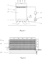
- a water collection trough assembly is arranged beneath the fill (2) of a cooling tower that is generally indicated by numeral (3) and can be made of metal, plastic or metal extrusion.
- the cooling tower includes a water collection sump (4), a circulating pump (5) for supplying recirculated coolant water to a heat generating process generally indicated by numeral (6); and a hot water distribution installation (7) at the top of the fill (2).
- a water collection facility (8) such as a delugable dephlegmator or an air cooled heat exchanger may be installed beneath a tube bundle (9) of a condensation device such as a dephlegmator, generally indicated by numeral (11).
- the water collection trough assembly comprises a plurality of elongate troughs (12) and associated inclined capture plates (13) wherein each capture plate is arranged to receive liquid contacting same on a front face (14) thereof and to direct the liquid into the associated elongate trough.
- the capture plate is, in each instance, arranged so that the troughs are spaced apart with the upper edge (15) of each of the capture plates being located over a lower edge region (16) of an adjacent capture plate to define inclined flow paths (17) for air between the capture plates.
- a capture plate may be formed as an upward extension of one wall of the trough in each case. That aspect of the arrangement is particularly illustrated in Figure 3 .
- Each elongate trough may be open at either or each end (18) to allow for drainage of liquid collected therein, typically into a manifold or other collection duct (19).
- a generally upright deflection plate (21) extends downwards from an upper region, in this instance the upper edge (15), of the capture plate on its rear face (22) so as to be capable of receiving liquid droplets contacting it and directing such liquid into the lower region of an adjacent capture plate or even the trough associated with the latter, in use.
- the upper region (23) of the capture plate is generally vertical and the deflection plate is superimposed over that upper region and extends downwards beyond it to terminate in a bottom edge (24) that is located downwards of the said upper region and spaced rearwards of the rear surface of the inclined portion of the capture plate.
- this arrangement causes the gap between the inclined portions of the two adjacent capture plates to be narrowed somewhat and it is important from the point of view of resistance to the upward flow of air that the lower edge of the deflection plate be suitably located.
- Each design will dictate its own preferred position of the lower edge of the deflection plate.
- the bottom edge of the deflection plate is located vertically above the lower region of the adjacent inclined capture plate so that drops forming on the deflection plate can run down and fall onto the lower region of the capture plate or even directly into the trough with which the latter is associated.
- the troughs are all arranged at an equal vertical height so that they are coplanar in a horizontal direction.
- the water collection troughs (31) may be located alternately at staggered vertical positions in vertically spaced horizontal planes with the capture plates (32) all being parallel and being of different lengths in the direction in which they extend so that the upper ends (33) are all coplanar in a single horizontal plane. In this instance the available area for flow of air is increased between adjacent troughs.
- the top edge region (35) of the capture plates (36) and any superimposed deflection plates (37) may be inwardly curved towards the front and upwardly directed face of the capture plate in a manner calculated to impart a change of direction to air passing between the capture plates.
- This change of direction is aimed at redirecting air passing in an inclined direction between adjacent capture plates to flow in a more vertically extending direction.
Landscapes
- Engineering & Computer Science (AREA)
- Physics & Mathematics (AREA)
- Thermal Sciences (AREA)
- Mechanical Engineering (AREA)
- General Engineering & Computer Science (AREA)
- Chemical & Material Sciences (AREA)
- Chemical Kinetics & Catalysis (AREA)
- Heat-Exchange Devices With Radiators And Conduit Assemblies (AREA)
Claims (8)
- Cuve de collecte de liquide (1) comprenant une pluralité de cuves allongées (12, 31) et plaques de captage inclinées connexes (13, 32, 36), chaque plaque de captage étant agencée pour recevoir un liquide la contactant sur une face antérieure (14) de celle-ci, et diriger le liquide dans une cuve allongée connexe, chaque plaque de captage possédant une plaque déflectrice de forme globalement verticale (21, 37) s'étendant vers le bas d'une zone supérieure de celle-ci sur sa face postérieure (22) afin d'être en mesure de recevoir des gouttelettes de liquide la contactant, et de diriger ce liquide dans ou sur une cuve ou plaque de captage adjacente utilisée, et
caractérisée en ce que
une zone latérale supérieure de chaque plaque de captage, et toute plaque déflectrice (21, 37) superposée étant verticale ou recourbée vers l'intérieur (35) en direction de la face de la plaque de captage (13, 32, 36) de façon qu'elle ait tendance à rediriger l'air passant dans une direction inclinée entre des plaques de captage adjacentes, dans une direction s'étendant de façon plus verticale. - Cuve de collecte de liquide selon la revendication 1, dans laquelle le cuves et les plaques de captage inclinées connexes sont espacées de sorte qu'un bord supérieur (15, 33) de chacune des plaques de captage est situé sur une zone à bord inférieur d'une plaque de captage adjacente pour définir des chemins d'écoulement inclinés (17) pour l'air entre les plaques de captage.
- Cuve de collecte de liquide selon une des revendications 1 ou 2, dans laquelle chaque plaque de captage est formée comme une extension vers le haut d'une paroi de la cuve.
- Cuve de collecte de liquide selon une quelconque des revendications précédentes, dans laquelle la plaque déflectrice est fixée le long d'un bord supérieur de la plaque de captage inclinée connexe.
- Cuve de collecte de liquide selon une quelconque des revendications précédentes, dans laquelle les cuves de collecte d'eau sont toutes agencées dans le même plan horizontal.
- Cuve de collecte de liquide selon une quelconque des revendications 1 à 4, dans laquelle les cuves de collecte d'eau sont agencées dans des positions verticales en quinconce avec un espacement régulier dans une pluralité de plans horizontaux à espacement vertical.
- Cuve de collecte de liquide selon une quelconque des revendications précédentes, dans laquelle chaque cuve allongée est ouverte à un ou chacun des bouts (18) afin de permettre le drainage du liquide recueilli dans celles-ci dans des collecteurs ou autres conduits de collecte (19).
- Cuve de collecte de liquide selon une quelconque des revendications précédentes, la cuve de collecte étant installée sous un dispositif de remplissage (2) ou un faisceau tubulaire d'une tour de refroidissement (3), d'un condenseur ou d'un déflegmateur.
Applications Claiming Priority (2)
| Application Number | Priority Date | Filing Date | Title |
|---|---|---|---|
| ZA201308443 | 2013-11-12 | ||
| PCT/IB2014/065949 WO2015071822A1 (fr) | 2013-11-12 | 2014-11-11 | Ensemble auget de collecte d'eau |
Publications (2)
| Publication Number | Publication Date |
|---|---|
| EP3069094A1 EP3069094A1 (fr) | 2016-09-21 |
| EP3069094B1 true EP3069094B1 (fr) | 2019-01-16 |
Family
ID=52003019
Family Applications (1)
| Application Number | Title | Priority Date | Filing Date |
|---|---|---|---|
| EP14806089.0A Not-in-force EP3069094B1 (fr) | 2013-11-12 | 2014-11-11 | Ensemble auget de collecte d'eau |
Country Status (7)
| Country | Link |
|---|---|
| US (1) | US9897399B2 (fr) |
| EP (1) | EP3069094B1 (fr) |
| JP (1) | JP2016539302A (fr) |
| CN (1) | CN105917189B (fr) |
| RU (1) | RU2656767C2 (fr) |
| WO (1) | WO2015071822A1 (fr) |
| ZA (1) | ZA201603207B (fr) |
Families Citing this family (7)
| Publication number | Priority date | Publication date | Assignee | Title |
|---|---|---|---|---|
| CN105333766B (zh) * | 2015-11-09 | 2017-07-11 | 中国能源建设集团广东省电力设计研究院有限公司 | 高位收水塔的冷却系统 |
| CN105352359B (zh) * | 2015-11-09 | 2017-08-04 | 中国能源建设集团广东省电力设计研究院有限公司 | 高位收水塔的填料系统 |
| US10775117B2 (en) | 2016-09-30 | 2020-09-15 | Baltimore Aircoil Company | Water collection/deflection arrangements |
| US10677543B2 (en) | 2017-08-31 | 2020-06-09 | Baltimore Aircoil Company, Inc. | Cooling tower |
| US11609051B2 (en) | 2020-04-13 | 2023-03-21 | Harold D. Revocable Trust | Apparatus for cooling liquid and collection assembly therefor |
| CN113566326B (zh) * | 2021-07-15 | 2022-11-25 | 珠海格力电器股份有限公司 | 湿帘组件及风扇 |
| CN113404722B (zh) * | 2021-07-15 | 2025-07-29 | 珠海格力电器股份有限公司 | 风扇结构及风扇 |
Family Cites Families (11)
| Publication number | Priority date | Publication date | Assignee | Title |
|---|---|---|---|---|
| US1647281A (en) * | 1926-04-01 | 1927-11-01 | Frank M Doyle | Cooling tower |
| GB734185A (en) * | 1951-03-27 | 1955-07-27 | Samuel Couzin | Improvements in installations for contacting liquids and gases particularly applicable to water cooling towers |
| DE2250776A1 (de) * | 1972-10-17 | 1974-04-18 | Schoell Guenter | Verfahren nebst vorrichtungen zur verminderung der pumpenarbeit fuer den kuehlwasserkreislauf in nasskuehltuermen |
| DE7717599U1 (de) * | 1977-06-03 | 1977-11-17 | Regehr, Ulrich, Dr.-Ing., 5100 Aachen | Lamellendeflektor zur abscheidung von in einem fluessigkeit-dampf-gemisch mitgefuehrter fluessigkeit |
| FR2493718A1 (fr) * | 1980-11-12 | 1982-05-14 | Hamon | Dispositif pour recueillir un liquide tombant librement et son application a une installation de mise en contact a contre-courant d'un liquide avec un gaz |
| US4521350A (en) * | 1984-01-16 | 1985-06-04 | The Munters Corporation | Drainage collection system |
| RU9059U1 (ru) * | 1998-06-16 | 1999-01-16 | Общество с ограниченной ответственностью "Специализированный трест эколого-технологических производств и проектов" | Блок водоуловителя градирни |
| WO2000062911A1 (fr) * | 1999-04-16 | 2000-10-26 | Ovard John C | Barres d'aspersion pour transfert direct de chaleur par contact et de masse, procede et appareil correspondants |
| CN201413077Y (zh) * | 2009-06-11 | 2010-02-24 | 中国电力工程顾问集团西北电力设计院 | 一种湿式冷却塔的收水装置 |
| US9273915B2 (en) * | 2009-07-17 | 2016-03-01 | Amistco Seperation Products, Inc. | Enhanced capacity, reduced turbulence, trough-type liquid collector trays |
| CN103234380B (zh) * | 2013-04-19 | 2016-03-09 | 国核电力规划设计研究院 | 一种冷却塔的集水装置和方法 |
-
2014
- 2014-11-11 WO PCT/IB2014/065949 patent/WO2015071822A1/fr not_active Ceased
- 2014-11-11 CN CN201480062088.8A patent/CN105917189B/zh not_active Expired - Fee Related
- 2014-11-11 RU RU2016122922A patent/RU2656767C2/ru not_active IP Right Cessation
- 2014-11-11 US US15/036,018 patent/US9897399B2/en not_active Expired - Fee Related
- 2014-11-11 JP JP2016529890A patent/JP2016539302A/ja active Pending
- 2014-11-11 EP EP14806089.0A patent/EP3069094B1/fr not_active Not-in-force
-
2016
- 2016-05-12 ZA ZA2016/03207A patent/ZA201603207B/en unknown
Non-Patent Citations (1)
| Title |
|---|
| None * |
Also Published As
| Publication number | Publication date |
|---|---|
| US20160290745A1 (en) | 2016-10-06 |
| EP3069094A1 (fr) | 2016-09-21 |
| RU2016122922A3 (fr) | 2018-05-08 |
| CN105917189A (zh) | 2016-08-31 |
| RU2656767C2 (ru) | 2018-06-06 |
| CN105917189B (zh) | 2018-01-16 |
| ZA201603207B (en) | 2017-07-26 |
| US9897399B2 (en) | 2018-02-20 |
| WO2015071822A1 (fr) | 2015-05-21 |
| RU2016122922A (ru) | 2017-12-12 |
| JP2016539302A (ja) | 2016-12-15 |
Similar Documents
| Publication | Publication Date | Title |
|---|---|---|
| US9897399B2 (en) | Water collection trough assembly | |
| US4683101A (en) | Cross flow evaporative coil fluid cooling apparatus and method of cooling | |
| US7779898B2 (en) | Heat transfer tube assembly with serpentine circuits | |
| US11255620B2 (en) | Water collection/deflection arrangement | |
| US10627176B2 (en) | Cooling tower water distribution system | |
| EP2972038B1 (fr) | Tour de refroidissement avec échangeur de chaleur indirect | |
| US9587885B2 (en) | Cooling tower with indirect heat exchanger | |
| US20140209279A1 (en) | Indirect heat exchanger | |
| US11150037B2 (en) | Heat exchange apparatus | |
| KR20120003359A (ko) | 냉각탑 | |
| CN201926095U (zh) | 换热装置 | |
| AU596941B2 (en) | Low silhouette cooling tower with trapezoidal fill and method of air flow therethrough | |
| US20100011795A1 (en) | Arrangement in connection with cooling element including condensate gutters | |
| CN117280163A (zh) | 绝热预冷再分配系统 | |
| US20180274863A1 (en) | Hybrid fluid cooler with extended intermediate basin nozzles | |
| CN114111120B (zh) | 降膜式翅片管换热器、空调系统 | |
| US20090188650A1 (en) | Liquid distribution in an evaporative heat rejection system | |
| CA2930357A1 (fr) | Ensemble auget de collecte d'eau | |
| CA1121338A (fr) | Echangeur de chaleur sur refroidisseur d'air | |
| CN224034058U (zh) | 一种蒸发式碳化硅冷凝器 | |
| AU2016247100B2 (en) | Cooling tower splash fill | |
| CN204007200U (zh) | 一种带填料板式蒸发冷却器 |
Legal Events
| Date | Code | Title | Description |
|---|---|---|---|
| PUAI | Public reference made under article 153(3) epc to a published international application that has entered the european phase |
Free format text: ORIGINAL CODE: 0009012 |
|
| 17P | Request for examination filed |
Effective date: 20160608 |
|
| AK | Designated contracting states |
Kind code of ref document: A1 Designated state(s): AL AT BE BG CH CY CZ DE DK EE ES FI FR GB GR HR HU IE IS IT LI LT LU LV MC MK MT NL NO PL PT RO RS SE SI SK SM TR |
|
| AX | Request for extension of the european patent |
Extension state: BA ME |
|
| DAX | Request for extension of the european patent (deleted) | ||
| STAA | Information on the status of an ep patent application or granted ep patent |
Free format text: STATUS: EXAMINATION IS IN PROGRESS |
|
| 17Q | First examination report despatched |
Effective date: 20180103 |
|
| GRAP | Despatch of communication of intention to grant a patent |
Free format text: ORIGINAL CODE: EPIDOSNIGR1 |
|
| STAA | Information on the status of an ep patent application or granted ep patent |
Free format text: STATUS: GRANT OF PATENT IS INTENDED |
|
| INTG | Intention to grant announced |
Effective date: 20180810 |
|
| RIN1 | Information on inventor provided before grant (corrected) |
Inventor name: REUTER, HANNO CARL RUDOLF Inventor name: KROEGER, DETLEV G. |
|
| GRAS | Grant fee paid |
Free format text: ORIGINAL CODE: EPIDOSNIGR3 |
|
| GRAA | (expected) grant |
Free format text: ORIGINAL CODE: 0009210 |
|
| STAA | Information on the status of an ep patent application or granted ep patent |
Free format text: STATUS: THE PATENT HAS BEEN GRANTED |
|
| AK | Designated contracting states |
Kind code of ref document: B1 Designated state(s): AL AT BE BG CH CY CZ DE DK EE ES FI FR GB GR HR HU IE IS IT LI LT LU LV MC MK MT NL NO PL PT RO RS SE SI SK SM TR |
|
| REG | Reference to a national code |
Ref country code: GB Ref legal event code: FG4D |
|
| REG | Reference to a national code |
Ref country code: CH Ref legal event code: EP |
|
| REG | Reference to a national code |
Ref country code: IE Ref legal event code: FG4D |
|
| REG | Reference to a national code |
Ref country code: DE Ref legal event code: R096 Ref document number: 602014040082 Country of ref document: DE |
|
| REG | Reference to a national code |
Ref country code: AT Ref legal event code: REF Ref document number: 1090003 Country of ref document: AT Kind code of ref document: T Effective date: 20190215 |
|
| REG | Reference to a national code |
Ref country code: NL Ref legal event code: MP Effective date: 20190116 |
|
| REG | Reference to a national code |
Ref country code: LT Ref legal event code: MG4D |
|
| PG25 | Lapsed in a contracting state [announced via postgrant information from national office to epo] |
Ref country code: NL Free format text: LAPSE BECAUSE OF FAILURE TO SUBMIT A TRANSLATION OF THE DESCRIPTION OR TO PAY THE FEE WITHIN THE PRESCRIBED TIME-LIMIT Effective date: 20190116 |
|
| REG | Reference to a national code |
Ref country code: AT Ref legal event code: MK05 Ref document number: 1090003 Country of ref document: AT Kind code of ref document: T Effective date: 20190116 |
|
| PG25 | Lapsed in a contracting state [announced via postgrant information from national office to epo] |
Ref country code: LT Free format text: LAPSE BECAUSE OF FAILURE TO SUBMIT A TRANSLATION OF THE DESCRIPTION OR TO PAY THE FEE WITHIN THE PRESCRIBED TIME-LIMIT Effective date: 20190116 Ref country code: SE Free format text: LAPSE BECAUSE OF FAILURE TO SUBMIT A TRANSLATION OF THE DESCRIPTION OR TO PAY THE FEE WITHIN THE PRESCRIBED TIME-LIMIT Effective date: 20190116 Ref country code: FI Free format text: LAPSE BECAUSE OF FAILURE TO SUBMIT A TRANSLATION OF THE DESCRIPTION OR TO PAY THE FEE WITHIN THE PRESCRIBED TIME-LIMIT Effective date: 20190116 Ref country code: PT Free format text: LAPSE BECAUSE OF FAILURE TO SUBMIT A TRANSLATION OF THE DESCRIPTION OR TO PAY THE FEE WITHIN THE PRESCRIBED TIME-LIMIT Effective date: 20190516 Ref country code: NO Free format text: LAPSE BECAUSE OF FAILURE TO SUBMIT A TRANSLATION OF THE DESCRIPTION OR TO PAY THE FEE WITHIN THE PRESCRIBED TIME-LIMIT Effective date: 20190416 Ref country code: ES Free format text: LAPSE BECAUSE OF FAILURE TO SUBMIT A TRANSLATION OF THE DESCRIPTION OR TO PAY THE FEE WITHIN THE PRESCRIBED TIME-LIMIT Effective date: 20190116 Ref country code: PL Free format text: LAPSE BECAUSE OF FAILURE TO SUBMIT A TRANSLATION OF THE DESCRIPTION OR TO PAY THE FEE WITHIN THE PRESCRIBED TIME-LIMIT Effective date: 20190116 |
|
| PG25 | Lapsed in a contracting state [announced via postgrant information from national office to epo] |
Ref country code: IS Free format text: LAPSE BECAUSE OF FAILURE TO SUBMIT A TRANSLATION OF THE DESCRIPTION OR TO PAY THE FEE WITHIN THE PRESCRIBED TIME-LIMIT Effective date: 20190516 Ref country code: LV Free format text: LAPSE BECAUSE OF FAILURE TO SUBMIT A TRANSLATION OF THE DESCRIPTION OR TO PAY THE FEE WITHIN THE PRESCRIBED TIME-LIMIT Effective date: 20190116 Ref country code: GR Free format text: LAPSE BECAUSE OF FAILURE TO SUBMIT A TRANSLATION OF THE DESCRIPTION OR TO PAY THE FEE WITHIN THE PRESCRIBED TIME-LIMIT Effective date: 20190417 Ref country code: HR Free format text: LAPSE BECAUSE OF FAILURE TO SUBMIT A TRANSLATION OF THE DESCRIPTION OR TO PAY THE FEE WITHIN THE PRESCRIBED TIME-LIMIT Effective date: 20190116 Ref country code: RS Free format text: LAPSE BECAUSE OF FAILURE TO SUBMIT A TRANSLATION OF THE DESCRIPTION OR TO PAY THE FEE WITHIN THE PRESCRIBED TIME-LIMIT Effective date: 20190116 Ref country code: BG Free format text: LAPSE BECAUSE OF FAILURE TO SUBMIT A TRANSLATION OF THE DESCRIPTION OR TO PAY THE FEE WITHIN THE PRESCRIBED TIME-LIMIT Effective date: 20190416 |
|
| REG | Reference to a national code |
Ref country code: DE Ref legal event code: R097 Ref document number: 602014040082 Country of ref document: DE |
|
| PG25 | Lapsed in a contracting state [announced via postgrant information from national office to epo] |
Ref country code: AT Free format text: LAPSE BECAUSE OF FAILURE TO SUBMIT A TRANSLATION OF THE DESCRIPTION OR TO PAY THE FEE WITHIN THE PRESCRIBED TIME-LIMIT Effective date: 20190116 Ref country code: CZ Free format text: LAPSE BECAUSE OF FAILURE TO SUBMIT A TRANSLATION OF THE DESCRIPTION OR TO PAY THE FEE WITHIN THE PRESCRIBED TIME-LIMIT Effective date: 20190116 Ref country code: RO Free format text: LAPSE BECAUSE OF FAILURE TO SUBMIT A TRANSLATION OF THE DESCRIPTION OR TO PAY THE FEE WITHIN THE PRESCRIBED TIME-LIMIT Effective date: 20190116 Ref country code: EE Free format text: LAPSE BECAUSE OF FAILURE TO SUBMIT A TRANSLATION OF THE DESCRIPTION OR TO PAY THE FEE WITHIN THE PRESCRIBED TIME-LIMIT Effective date: 20190116 Ref country code: IT Free format text: LAPSE BECAUSE OF FAILURE TO SUBMIT A TRANSLATION OF THE DESCRIPTION OR TO PAY THE FEE WITHIN THE PRESCRIBED TIME-LIMIT Effective date: 20190116 Ref country code: DK Free format text: LAPSE BECAUSE OF FAILURE TO SUBMIT A TRANSLATION OF THE DESCRIPTION OR TO PAY THE FEE WITHIN THE PRESCRIBED TIME-LIMIT Effective date: 20190116 Ref country code: SK Free format text: LAPSE BECAUSE OF FAILURE TO SUBMIT A TRANSLATION OF THE DESCRIPTION OR TO PAY THE FEE WITHIN THE PRESCRIBED TIME-LIMIT Effective date: 20190116 Ref country code: AL Free format text: LAPSE BECAUSE OF FAILURE TO SUBMIT A TRANSLATION OF THE DESCRIPTION OR TO PAY THE FEE WITHIN THE PRESCRIBED TIME-LIMIT Effective date: 20190116 |
|
| PLBE | No opposition filed within time limit |
Free format text: ORIGINAL CODE: 0009261 |
|
| STAA | Information on the status of an ep patent application or granted ep patent |
Free format text: STATUS: NO OPPOSITION FILED WITHIN TIME LIMIT |
|
| PG25 | Lapsed in a contracting state [announced via postgrant information from national office to epo] |
Ref country code: SM Free format text: LAPSE BECAUSE OF FAILURE TO SUBMIT A TRANSLATION OF THE DESCRIPTION OR TO PAY THE FEE WITHIN THE PRESCRIBED TIME-LIMIT Effective date: 20190116 |
|
| 26N | No opposition filed |
Effective date: 20191017 |
|
| PG25 | Lapsed in a contracting state [announced via postgrant information from national office to epo] |
Ref country code: SI Free format text: LAPSE BECAUSE OF FAILURE TO SUBMIT A TRANSLATION OF THE DESCRIPTION OR TO PAY THE FEE WITHIN THE PRESCRIBED TIME-LIMIT Effective date: 20190116 |
|
| PGFP | Annual fee paid to national office [announced via postgrant information from national office to epo] |
Ref country code: FR Payment date: 20191121 Year of fee payment: 6 |
|
| PG25 | Lapsed in a contracting state [announced via postgrant information from national office to epo] |
Ref country code: TR Free format text: LAPSE BECAUSE OF FAILURE TO SUBMIT A TRANSLATION OF THE DESCRIPTION OR TO PAY THE FEE WITHIN THE PRESCRIBED TIME-LIMIT Effective date: 20190116 |
|
| REG | Reference to a national code |
Ref country code: CH Ref legal event code: PL |
|
| PG25 | Lapsed in a contracting state [announced via postgrant information from national office to epo] |
Ref country code: LI Free format text: LAPSE BECAUSE OF NON-PAYMENT OF DUE FEES Effective date: 20191130 Ref country code: LU Free format text: LAPSE BECAUSE OF NON-PAYMENT OF DUE FEES Effective date: 20191111 Ref country code: MC Free format text: LAPSE BECAUSE OF FAILURE TO SUBMIT A TRANSLATION OF THE DESCRIPTION OR TO PAY THE FEE WITHIN THE PRESCRIBED TIME-LIMIT Effective date: 20190116 Ref country code: CH Free format text: LAPSE BECAUSE OF NON-PAYMENT OF DUE FEES Effective date: 20191130 |
|
| REG | Reference to a national code |
Ref country code: BE Ref legal event code: MM Effective date: 20191130 |
|
| PG25 | Lapsed in a contracting state [announced via postgrant information from national office to epo] |
Ref country code: IE Free format text: LAPSE BECAUSE OF NON-PAYMENT OF DUE FEES Effective date: 20191111 |
|
| PG25 | Lapsed in a contracting state [announced via postgrant information from national office to epo] |
Ref country code: BE Free format text: LAPSE BECAUSE OF NON-PAYMENT OF DUE FEES Effective date: 20191130 |
|
| PGFP | Annual fee paid to national office [announced via postgrant information from national office to epo] |
Ref country code: GB Payment date: 20201123 Year of fee payment: 7 Ref country code: DE Payment date: 20201125 Year of fee payment: 7 |
|
| PG25 | Lapsed in a contracting state [announced via postgrant information from national office to epo] |
Ref country code: CY Free format text: LAPSE BECAUSE OF FAILURE TO SUBMIT A TRANSLATION OF THE DESCRIPTION OR TO PAY THE FEE WITHIN THE PRESCRIBED TIME-LIMIT Effective date: 20190116 |
|
| PG25 | Lapsed in a contracting state [announced via postgrant information from national office to epo] |
Ref country code: HU Free format text: LAPSE BECAUSE OF FAILURE TO SUBMIT A TRANSLATION OF THE DESCRIPTION OR TO PAY THE FEE WITHIN THE PRESCRIBED TIME-LIMIT; INVALID AB INITIO Effective date: 20141111 Ref country code: MT Free format text: LAPSE BECAUSE OF FAILURE TO SUBMIT A TRANSLATION OF THE DESCRIPTION OR TO PAY THE FEE WITHIN THE PRESCRIBED TIME-LIMIT Effective date: 20190116 |
|
| PG25 | Lapsed in a contracting state [announced via postgrant information from national office to epo] |
Ref country code: FR Free format text: LAPSE BECAUSE OF NON-PAYMENT OF DUE FEES Effective date: 20201130 |
|
| REG | Reference to a national code |
Ref country code: DE Ref legal event code: R119 Ref document number: 602014040082 Country of ref document: DE |
|
| PG25 | Lapsed in a contracting state [announced via postgrant information from national office to epo] |
Ref country code: MK Free format text: LAPSE BECAUSE OF FAILURE TO SUBMIT A TRANSLATION OF THE DESCRIPTION OR TO PAY THE FEE WITHIN THE PRESCRIBED TIME-LIMIT Effective date: 20190116 |
|
| GBPC | Gb: european patent ceased through non-payment of renewal fee |
Effective date: 20211111 |
|
| PG25 | Lapsed in a contracting state [announced via postgrant information from national office to epo] |
Ref country code: GB Free format text: LAPSE BECAUSE OF NON-PAYMENT OF DUE FEES Effective date: 20211111 Ref country code: DE Free format text: LAPSE BECAUSE OF NON-PAYMENT OF DUE FEES Effective date: 20220601 |