EP3069676B1 - Schwingungserzeugungseinheit, schwingkörpereinheit und ultraschallbehandlungsvorrichtung - Google Patents
Schwingungserzeugungseinheit, schwingkörpereinheit und ultraschallbehandlungsvorrichtung Download PDFInfo
- Publication number
- EP3069676B1 EP3069676B1 EP14861721.0A EP14861721A EP3069676B1 EP 3069676 B1 EP3069676 B1 EP 3069676B1 EP 14861721 A EP14861721 A EP 14861721A EP 3069676 B1 EP3069676 B1 EP 3069676B1
- Authority
- EP
- European Patent Office
- Prior art keywords
- vibration
- section
- ultrasonic
- proximal
- generating unit
- Prior art date
- Legal status (The legal status is an assumption and is not a legal conclusion. Google has not performed a legal analysis and makes no representation as to the accuracy of the status listed.)
- Active
Links
Images






Classifications
-
- B—PERFORMING OPERATIONS; TRANSPORTING
- B06—GENERATING OR TRANSMITTING MECHANICAL VIBRATIONS IN GENERAL
- B06B—METHODS OR APPARATUS FOR GENERATING OR TRANSMITTING MECHANICAL VIBRATIONS OF INFRASONIC, SONIC, OR ULTRASONIC FREQUENCY, e.g. FOR PERFORMING MECHANICAL WORK IN GENERAL
- B06B3/00—Methods or apparatus specially adapted for transmitting mechanical vibrations of infrasonic, sonic, or ultrasonic frequency
- B06B3/02—Methods or apparatus specially adapted for transmitting mechanical vibrations of infrasonic, sonic, or ultrasonic frequency involving a change of amplitude
-
- B—PERFORMING OPERATIONS; TRANSPORTING
- B06—GENERATING OR TRANSMITTING MECHANICAL VIBRATIONS IN GENERAL
- B06B—METHODS OR APPARATUS FOR GENERATING OR TRANSMITTING MECHANICAL VIBRATIONS OF INFRASONIC, SONIC, OR ULTRASONIC FREQUENCY, e.g. FOR PERFORMING MECHANICAL WORK IN GENERAL
- B06B3/00—Methods or apparatus specially adapted for transmitting mechanical vibrations of infrasonic, sonic, or ultrasonic frequency
-
- A—HUMAN NECESSITIES
- A61—MEDICAL OR VETERINARY SCIENCE; HYGIENE
- A61N—ELECTROTHERAPY; MAGNETOTHERAPY; RADIATION THERAPY; ULTRASOUND THERAPY
- A61N1/00—Electrotherapy; Circuits therefor
- A61N1/02—Details
- A61N1/04—Electrodes
- A61N1/0404—Electrodes for external use
- A61N1/0472—Structure-related aspects
- A61N1/0476—Array electrodes (including any electrode arrangement with more than one electrode for at least one of the polarities)
-
- A—HUMAN NECESSITIES
- A61—MEDICAL OR VETERINARY SCIENCE; HYGIENE
- A61N—ELECTROTHERAPY; MAGNETOTHERAPY; RADIATION THERAPY; ULTRASOUND THERAPY
- A61N1/00—Electrotherapy; Circuits therefor
- A61N1/02—Details
- A61N1/04—Electrodes
- A61N1/0404—Electrodes for external use
- A61N1/0472—Structure-related aspects
- A61N1/0484—Garment electrodes worn by the patient
-
- A—HUMAN NECESSITIES
- A61—MEDICAL OR VETERINARY SCIENCE; HYGIENE
- A61N—ELECTROTHERAPY; MAGNETOTHERAPY; RADIATION THERAPY; ULTRASOUND THERAPY
- A61N1/00—Electrotherapy; Circuits therefor
- A61N1/18—Applying electric currents by contact electrodes
- A61N1/32—Applying electric currents by contact electrodes alternating or intermittent currents
- A61N1/36—Applying electric currents by contact electrodes alternating or intermittent currents for stimulation
- A61N1/36014—External stimulators, e.g. with patch electrodes
- A61N1/36025—External stimulators, e.g. with patch electrodes for treating a mental or cerebral condition
-
- B—PERFORMING OPERATIONS; TRANSPORTING
- B06—GENERATING OR TRANSMITTING MECHANICAL VIBRATIONS IN GENERAL
- B06B—METHODS OR APPARATUS FOR GENERATING OR TRANSMITTING MECHANICAL VIBRATIONS OF INFRASONIC, SONIC, OR ULTRASONIC FREQUENCY, e.g. FOR PERFORMING MECHANICAL WORK IN GENERAL
- B06B1/00—Methods or apparatus for generating mechanical vibrations of infrasonic, sonic, or ultrasonic frequency
- B06B1/02—Methods or apparatus for generating mechanical vibrations of infrasonic, sonic, or ultrasonic frequency making use of electrical energy
- B06B1/06—Methods or apparatus for generating mechanical vibrations of infrasonic, sonic, or ultrasonic frequency making use of electrical energy operating with piezoelectric effect or with electrostriction
-
- A—HUMAN NECESSITIES
- A61—MEDICAL OR VETERINARY SCIENCE; HYGIENE
- A61B—DIAGNOSIS; SURGERY; IDENTIFICATION
- A61B17/00—Surgical instruments, devices or methods
- A61B2017/00017—Electrical control of surgical instruments
- A61B2017/00022—Sensing or detecting at the treatment site
- A61B2017/00026—Conductivity or impedance, e.g. of tissue
- A61B2017/0003—Conductivity or impedance, e.g. of tissue of parts of the instruments
-
- A—HUMAN NECESSITIES
- A61—MEDICAL OR VETERINARY SCIENCE; HYGIENE
- A61B—DIAGNOSIS; SURGERY; IDENTIFICATION
- A61B17/00—Surgical instruments, devices or methods
- A61B2017/00017—Electrical control of surgical instruments
- A61B2017/00022—Sensing or detecting at the treatment site
- A61B2017/00106—Sensing or detecting at the treatment site ultrasonic
-
- A—HUMAN NECESSITIES
- A61—MEDICAL OR VETERINARY SCIENCE; HYGIENE
- A61B—DIAGNOSIS; SURGERY; IDENTIFICATION
- A61B17/00—Surgical instruments, devices or methods
- A61B17/22—Implements for squeezing-off ulcers or the like on inner organs of the body; Implements for scraping-out cavities of body organs, e.g. bones; for invasive removal or destruction of calculus using mechanical vibrations; for removing obstructions in blood vessels, not otherwise provided for
- A61B17/22004—Implements for squeezing-off ulcers or the like on inner organs of the body; Implements for scraping-out cavities of body organs, e.g. bones; for invasive removal or destruction of calculus using mechanical vibrations; for removing obstructions in blood vessels, not otherwise provided for using mechanical vibrations, e.g. ultrasonic shock waves
- A61B17/22012—Implements for squeezing-off ulcers or the like on inner organs of the body; Implements for scraping-out cavities of body organs, e.g. bones; for invasive removal or destruction of calculus using mechanical vibrations; for removing obstructions in blood vessels, not otherwise provided for using mechanical vibrations, e.g. ultrasonic shock waves in direct contact with, or very close to, the obstruction or concrement
- A61B2017/22014—Implements for squeezing-off ulcers or the like on inner organs of the body; Implements for scraping-out cavities of body organs, e.g. bones; for invasive removal or destruction of calculus using mechanical vibrations; for removing obstructions in blood vessels, not otherwise provided for using mechanical vibrations, e.g. ultrasonic shock waves in direct contact with, or very close to, the obstruction or concrement the ultrasound transducer being outside patient's body; with an ultrasound transmission member; with a wave guide; with a vibrated guide wire
- A61B2017/22015—Implements for squeezing-off ulcers or the like on inner organs of the body; Implements for scraping-out cavities of body organs, e.g. bones; for invasive removal or destruction of calculus using mechanical vibrations; for removing obstructions in blood vessels, not otherwise provided for using mechanical vibrations, e.g. ultrasonic shock waves in direct contact with, or very close to, the obstruction or concrement the ultrasound transducer being outside patient's body; with an ultrasound transmission member; with a wave guide; with a vibrated guide wire with details of the transmission member
- A61B2017/22018—Implements for squeezing-off ulcers or the like on inner organs of the body; Implements for scraping-out cavities of body organs, e.g. bones; for invasive removal or destruction of calculus using mechanical vibrations; for removing obstructions in blood vessels, not otherwise provided for using mechanical vibrations, e.g. ultrasonic shock waves in direct contact with, or very close to, the obstruction or concrement the ultrasound transducer being outside patient's body; with an ultrasound transmission member; with a wave guide; with a vibrated guide wire with details of the transmission member segmented along its length
-
- A—HUMAN NECESSITIES
- A61—MEDICAL OR VETERINARY SCIENCE; HYGIENE
- A61B—DIAGNOSIS; SURGERY; IDENTIFICATION
- A61B17/00—Surgical instruments, devices or methods
- A61B17/32—Surgical cutting instruments
- A61B17/320068—Surgical cutting instruments using mechanical vibrations, e.g. ultrasonic
- A61B2017/320069—Surgical cutting instruments using mechanical vibrations, e.g. ultrasonic for ablating tissue
-
- A—HUMAN NECESSITIES
- A61—MEDICAL OR VETERINARY SCIENCE; HYGIENE
- A61B—DIAGNOSIS; SURGERY; IDENTIFICATION
- A61B17/00—Surgical instruments, devices or methods
- A61B17/32—Surgical cutting instruments
- A61B17/320068—Surgical cutting instruments using mechanical vibrations, e.g. ultrasonic
- A61B2017/32007—Surgical cutting instruments using mechanical vibrations, e.g. ultrasonic with suction or vacuum means
-
- A—HUMAN NECESSITIES
- A61—MEDICAL OR VETERINARY SCIENCE; HYGIENE
- A61B—DIAGNOSIS; SURGERY; IDENTIFICATION
- A61B17/00—Surgical instruments, devices or methods
- A61B17/32—Surgical cutting instruments
- A61B17/320068—Surgical cutting instruments using mechanical vibrations, e.g. ultrasonic
- A61B2017/320071—Surgical cutting instruments using mechanical vibrations, e.g. ultrasonic with articulating means for working tip
-
- A—HUMAN NECESSITIES
- A61—MEDICAL OR VETERINARY SCIENCE; HYGIENE
- A61B—DIAGNOSIS; SURGERY; IDENTIFICATION
- A61B17/00—Surgical instruments, devices or methods
- A61B17/32—Surgical cutting instruments
- A61B17/320068—Surgical cutting instruments using mechanical vibrations, e.g. ultrasonic
- A61B2017/320082—Surgical cutting instruments using mechanical vibrations, e.g. ultrasonic for incising tissue
-
- A—HUMAN NECESSITIES
- A61—MEDICAL OR VETERINARY SCIENCE; HYGIENE
- A61B—DIAGNOSIS; SURGERY; IDENTIFICATION
- A61B17/00—Surgical instruments, devices or methods
- A61B17/32—Surgical cutting instruments
- A61B17/320068—Surgical cutting instruments using mechanical vibrations, e.g. ultrasonic
- A61B2017/320089—Surgical cutting instruments using mechanical vibrations, e.g. ultrasonic node location
-
- A—HUMAN NECESSITIES
- A61—MEDICAL OR VETERINARY SCIENCE; HYGIENE
- A61B—DIAGNOSIS; SURGERY; IDENTIFICATION
- A61B17/00—Surgical instruments, devices or methods
- A61B17/32—Surgical cutting instruments
- A61B17/320068—Surgical cutting instruments using mechanical vibrations, e.g. ultrasonic
- A61B17/320092—Surgical cutting instruments using mechanical vibrations, e.g. ultrasonic with additional movable means for clamping or cutting tissue, e.g. with a pivoting jaw
- A61B2017/320095—Surgical cutting instruments using mechanical vibrations, e.g. ultrasonic with additional movable means for clamping or cutting tissue, e.g. with a pivoting jaw with sealing or cauterizing means
Definitions
- the present invention relates to a vibration generating unit configured to generate an ultrasonic vibration for use in a treatment in an ultrasonic treatment apparatus in which a treatment section gives a treatment to a treated target by using the ultrasonic vibration. Further, the present invention also relates to a vibrating body unit including the treatment section and the vibration generating unit, and to the ultrasonic treatment apparatus including the vibrating body unit.
- Patent Literature 1 discloses an ultrasonic treatment apparatus including a surgery tip provided in a distal portion thereof as a treatment section.
- a vibration generating unit including a piezoelectric crystal (a piezoelectric element) configured to convert an electric current into an ultrasonic vibration is provided.
- a vibration transmitting rod On a distal direction side of the vibration generating unit, a vibration transmitting rod is extended.
- the surgery tip On a distal direction side of the vibration transmitting rod, the surgery tip is attached. The ultrasonic vibration generated by the piezoelectric crystal is transmitted from the proximal direction toward the distal direction through the vibration transmitting rod.
- the surgery tip gives a treatment to a treated target such as a biological tissue by using the transmitted ultrasonic vibration.
- the vibration transmitting rod and the surgery tip form a distal side vibration transmitting section which is connected to the distal direction side of the vibration generating unit, and to which the ultrasonic vibration is transmitted from the vibration generating unit.
- the vibration generating unit, the vibration transmitting rod, and the surgery tip form a vibrating body unit.
- an ultrasonic vibration-transmittable stud is extended along with the longitudinal direction, and a shoulder is provided in the stud.
- a wave generator having piezoelectric crystal disks is attached.
- the wave generator is abutted to the shoulder of the stud from the proximal side, and the rear mass is abutted to the wave generator from the proximal side, thereby providing the wave generator between the shoulder and the rear mass with respect to the longitudinal direction.
- a step having a decreasing cross-sectional area toward the proximal side is formed in the rear mass.
- the stud is extended from the proximal end of the rear mass toward the further proximal side, and a step is formed in the proximal end of the rear mass.
- an ultrasonic transducer is movable between striking platens with respect to the proximal shaft.
- an anti-node is located at the driving platen, and an anti-node which is separated from the driving platen for a half wavelength on the proximal side, is located at the removing platen.
- the driving platen is connected to the distal striking platen, ultrasonic vibration is transmitted from the ultrasonic transducer to the proximal shaft and the waveguide, and the ultrasonic transducer and the proximal shaft vibrate together.
- an anti-node is located at the driving platen and the distal striking platen, and an anti-node which is separated from the driving platen for a half wavelength on the proximal side is located at the removing platen. Further, an anti-node which is separated from the driving platen for one wavelength on the proximal side is located at the proximal striking platen. Even when the removing platen is connected to the proximal striking platen, ultrasonic vibration is transmitted from the ultrasonic transducer to the proximal shaft and the waveguide, and the ultrasonic transducer and the proximal shaft vibrate together.
- an anti-node is located at the removing platen and the proximal striking platen, and an antinode which is separated from the removing platen for a half wavelength on the distal side is located at the driving platen.
- An anti-node which is separated from the removing platen for one wavelength on the distal side is located at the distal striking platen.
- an ultrasonic vibrator is provided to generate ultrasonic vibration, and an output control unit which controls supply of electric energy to the ultrasonic vibrator detects a resonance frequency of the ultrasonic vibrator.
- the Young's modulus varies in accordance with each distal side vibration transmitting section, even if the same vibration generating unit is used, a resonance frequency provided by the ultrasonic vibration in the vibrating body unit (the vibration generating unit, the vibration transmitting rod, and the surgery tip) varies in accordance with a change in the distal side vibration transmitting section connected to the vibration generating unit. That is, the variation in the Young's modulus according each distal side vibration transmitting section affects the resonance frequency of the vibrating body unit, and the resonance frequency of the vibrating body unit varies due to the variation in the Young's modulus according to each distal side vibration transmitting section.
- an object of the present invention to provide a vibration generating unit that realizes a reduction of a variation in resonance frequency of a vibrating body unit even if the Young's modulus varies in accordance with each distal side vibration transmitting section.
- another object is to provide a vibrating body unit including the vibration generating unit and the distal side vibration transmitting section, and an ultrasonic treatment apparatus including the vibrating body unit.
- a vibration generating unit with which a distal side vibration transmitting section is connected from a distal direction side, the distal side vibration transmitting section including a treatment section provided in a distal portion thereof, and the vibration generating unit being configured to generate an ultrasonic vibration transmitted to the distal side vibration transmitting section includes the features of claim 1.
- Preferred embodiments of the invention are illustrated in the dependent claims.
- a vibration generating unit which realizes a reduction of a variation in resonance frequency of a vibrating body unit even if the Young's modulus varies in accordance with each distal side vibration transmitting section, can be provided.
- a vibrating body unit including the vibration generating unit and the distal side vibration transmitting section, and an ultrasonic treatment apparatus including the vibrating body unit can be provided.
- FIG. 1 is a view showing a test vibrating body 100 used in verification of a vibration state.
- the verification of a vibration state is carried out by, e.g., simulation, and a relationship between the Young's modulus (E) and a resonance frequency (Fr) is verified with the use of a test vibrating body 100.
- E Young's modulus
- Fr resonance frequency
- the test vibrating body 100 is extended along an extension axis T.
- one side of directions parallel to the extension axis T is determined as a first extending direction (a direction of an arrow T1 in FIG. 1 ), and an opposite direction of the first extending direction is determined as a second extending direction (a direction of an arrow T2 in FIG. 1 ).
- an ultrasonic vibration is transmitted from the first extending direction toward the second extending direction.
- the test vibrating bod 100 has antinode positions A'1 to A'6 and node positions N'1 to N'5. That is, the test vibrating body 100 vibrates in a predetermined vibration state having the antinode positions A'1 to A'6 and the node positions N'1 to N'5 by transmitting the ultrasonic vibration.
- a first transmitting region 101, a second transmitting region 102, a third transmitting region 103, a fourth transmitting region 104, and a fifth transmitting region 105 are sequentially extended from the first extending direction.
- the first transmitting region 101 is extended between the antinode position A'1 and the antinode position A'2
- the second transmitting region 102 is extended between the antinode position A'2 and the antinode position A'3
- the third extending region 103 is extended between the antinode position A'3 and the antinode position A'4
- the fourth transmitting region 104 is extended between the antinode position A'4 and the antinode position A'5
- the fifth transmitting region 105 is extended between the antinode position A'5 and the antinode position A'6.
- the third transmitting region 103 includes a cross-sectional area reducing section 106, a first extending section 107 extended from the cross-sectional area reducing section 106 toward the first extending direction, and a second extending section 108 extended from the cross-sectional area reducing portion 106 toward the second extending direction.
- the node position N'3 on which stress caused by the ultrasonic vibration acts is placed at the cross-sectional area reducing section 106.
- a cross-sectional area of the second extending section 108 perpendicular to the extension axis T is smaller than that of the first extending section 107 due to the cross-sectional area reducing section 106.
- each of the first transmitting region 101, the second transmitting region 102, and the first extending section 107 of the third transmitting region 103 has a cross-sectional S1 perpendicular to the extension axis T.
- a cross-sectional area perpendicular to the extension axis T is S2, which is smaller than the cross-sectional area S1.
- a cross-sectional area increasing section 109 is provided at the antinode position A'4 between the third transmitting region 103 and the fourth transmitting region 104. That is, when the test vibrating body 100 vibrates in a predetermined vibration state, the antinode position A'3 is placed at the cross-sectional area increasing section 109. A cross-sectional area of the fourth transmitting region 104 perpendicular to the extension axis T becomes larger than that of the second extending section 108 of the third transmitting region 103 by the cross-sectional area increasing section 109. However, at the antinode position A'3 placed at the cross-sectional area increasing section 109, the stress caused by the ultrasonic vibration becomes zero.
- a cross-sectional area perpendicular to the extension axis T in the fourth transmitting region 104 and the fifth transmitting region 105 is the same as that in the first transmitting region 101 and the second transmitting region 102, and it is hence S1.
- a relationship between the Young's modulus (E) and a resonance frequency (Fr) was verified by changing a transformation ratio (an increasing ratio) of the ultrasonic vibration in the cross-sectional area reducing section 106. That is, the verification was performed by changing a ratio of the cross-sectional area S1 of the first extending section 107 perpendicular to the extension axis T relative to the cross-sectional area S2 of the second extending section 108 perpendicular to the extension axis T. Further, at each transformation ratio, a change in the resonance frequency (Fr) of the test vibrating body 100 relative to a change in the Young's modulus (E) in the fourth transmitting region 104 was verified.
- a transformation ratio an increasing ratio
- the change in the Young's modulus (E) in the fourth transmitting region 104 further seriously affects the resonance frequency (Fr) of the test vibrating body 100 as the transformation ratio of the ultrasonic vibration in the cross-sectional area reducing section 106 increases. That is, as the amplitude of the ultrasonic vibration in the fourth transmitting region 104 increases, an influence of the Young's modulus (E) of the fourth transmitting region 104 on the resonance frequency (Fr) of the test vibrating body 100 becomes considerable.
- the Young's modulus (E) of the fifth transmitting region 105 was changed, the same result in the case where the Young's modulus (E) of the fourth transmitting region 104 was changed was provided.
- the relationship between the Young's modulus (E) and the resonance frequency (Fr) shows a tendency different from that in the case where the Young's modulus (E) is changed in the fourth transmitting region 104 (the fifth transmitting region 105).
- a volume of the third transmitting region 103 affects the relationship between the Young's modulus (E) and the resonance frequency (Fr). That is, it was verified that an influence of the Young's modulus on the resonance frequency (Fr) increases in a region having a higher volume.
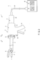
- FIG. 2 is a view showing a configuration of an ultrasonic treatment apparatus 1 according to this embodiment.
- the ultrasonic treatment apparatus 1 includes a hand piece (a treatment unit) 2 which is an ultrasonic treatment instrument, and a transducer unit 3 coupled with the hand piece 2.
- the ultrasonic treatment apparatus 1 has a longitudinal axis C running through the hand piece 2 and the transducer unit 3.
- a distal direction a direction of an arrow C1 in FIG. 2
- an opposite direction of the distal direction is determined as a proximal direction (a direction of an arrow C2 in FIG.
- the vibrator unit 3 is coupled with the hand piece 2 from the proximal direction side.
- the hand piece 2 is an ultrasonic incising-and-coagulation treatment instrument which simultaneously coagulates and incises a treated target such as a biological tissue by using an ultrasonic vibration.
- the hand piece 2 includes a holding unit 5, a sheath 6, an ultrasonic probe 7 which is a distal side vibration transmitting section, and a jaw 8.
- the holding unit 5 includes a tubular case section 11 extended along the longitudinal axis C, a fixed handle 12 integrally formed with the tubular case section 11, and a movable handle 13 attached to the tubular case portion 11 to allow its turning motion. When the movable handle 13 pivots around a position at which it is attached to the tubular case section 11, the movable handle 13 opens or closes relative to the fixed handle 12.
- the holding unit 5 includes a rotary operation knob 15 attached on the distal direction side of the tubular case section 11. The rotary operation knob 15 can rotate around the longitudinal axis C relative to the tubular case section 11. Further, a supply operation input button 16 which is a supply operation input section is disposed to the fixed handle 12.
- the sheath 6 is extended along the longitudinal axis C.
- the ultrasonic probe 7 which is the distal side vibration transmitting section is extended along the longitudinal axis C from the inside of the tubular case section 11 toward the distal direction. Furthermore, the ultrasonic probe 7 is inserted through the sheath 6.
- a treatment section 17 protruding from the distal end of the sheath 6 toward the distal direction is provided in the ultrasonic probe 7.
- the jaw 8 is attached to the distal portion of the sheath 6 to allow its turning motion.
- the movable handle 13 is connected to a movable tubular portion (not shown) of the sheath 6 inside the tubular case section 11.
- the distal end of the movable tubular portion is connected to the jaw 8.
- the movable handle 13 is opened or closed relative to the fixed handle 12
- the movable tubular portion moves along the longitudinal axis C. Consequently, the jaw 8 turns around the position at which it is attached to the sheath 6, and opens or closes relative to the treatment section 17 of the ultrasonic probe 7.
- the sheath 6, the ultrasonic probe 7, and the jaw 8 can rotate around the longitudinal axis C relative to the tubular case section 11 integrally with the rotary operation knob 15.
- the electric power supply unit 20 includes a current supply section 21 configured to output an electric current, and a supply control section 22 configured to control the current supply section 21.
- the current supply section 21 is formed of, e.g., an electric power supply and an amplification circuit (a drive circuit) or the like
- the supply control section 22 is formed of, e.g., a CPU (Central Processing Unit) or an ASIC (application specific integrated circuit), and a storage section such as a memory.
- the electric power supply unit 20 is an electric power supply device including, e.g., components, circuits, and others that form the current supply section 21 and the supply control section 22.
- FIG. 3 is a view showing a configuration of the transducer unit 3.
- the vibrator unit includes an outer transducer case 25, and an inner transducer case 26 placed inside the outer vibrator case 25.
- the outer transducer case 25 and the inner transducer case 26 are extended along the longitudinal axis C, and inserted into the tubular case section 11 of the holding unit 5 from the proximal direction side. Further, the outer vibrator case 25 and the inner vibrator case 26 are coupled with the sheath 6 inside the tubular case section 11.
- a vibration generating unit 30 configured to generate an ultrasonic vibration is provided inside the inner transducer case 26.
- the outer transducer case 25, the inner transducer case 26, and the vibration generating unit 30 form the transducer unit 3.
- the vibration generating unit 30 includes an ultrasonic transducer 31.
- the ultrasonic transducer 31 includes (in this embodiment, four) piezoelectric elements 32A to 32D which convert an electric current into the ultrasonic vibration, and two electrode sections 33A and 33B.
- a direction to get away from the longitudinal axis C in a cross section perpendicular to the longitudinal axis C is determined as an outer peripheral direction (an abaxial direction), and the opposite direction of the outer peripheral direction is determined as an inner peripheral direction (an adaxial direction). Furthermore, the outer peripheral direction and the circumferential direction are determined as a radial direction.
- Two through holes 27A and 27B that are pierced in the inner transducer case 26 in the radial direction are formed in the inner transducer case 26.
- a gap portion 28 is formed between the outer transducer case 25 and the inner transducer case 26 in the radial direction.
- the electrode section 33A includes a protruding portion 35A protruding from the through hole 27A to the gap portion 28 toward the outer peripheral direction. Additionally, the electrode section 33B includes a protruding portion 35B protruding from the through hole 27B to the gap portion 28 toward the outer peripheral direction.
- One end of an electrical wiring 36A is connected to the protruding portion 35A of the electrode section 33A. Further, one end of an electrical wiring 36B is connected to the protruding portion 35B of the electrode section 33B.
- the electrical wirings 36A and 36B are extended through the gap portion 28 and an inside of the cable 18.
- the other end of each of the electrical wirings 36A and 36B is connected to the current supply section 21 of the electric power supply unit 20.
- the vibration generating unit 30 includes a columnar horn member 37 to which the ultrasonic oscillator 31 is attached.
- the horn member 37 is extended along the longitudinal axis C.
- the horn member 37 includes a transducer attachment section 38 to which the ultrasonic transducer 31 is attached.
- a cross-sectional area change section 41 is formed in the horn member 37 on the distal direction side with respect to the transducer attachment section 38. In the cross-sectional area change section 41, a cross-sectional area perpendicular to the longitudinal axis C is reduced from the proximal direction toward the distal direction.
- a female screw section 42 is formed in a distal portion of the horn member 38.
- the female screw section 42 is placed on the distal direction side with respect to the cross-sectional area change section 41.
- a male screw section 43 is formed in a proximal portion of the transducer attachment section 38.
- the vibration generating unit 30 includes a columnar rod-shaped member 45 which is a proximal side vibration transmitting section extended along the longitudinal axis C in a part located on the proximal direction side with respect to the transducer attachment section 38.
- the ultrasonic probe 7 is connected to the distal direction side of the vibration generating unit 30.
- the ultrasonic probe 7 is connected to the vibration generating unit 30 inside the tubular case section 11.
- a vibrating body unit 10 that vibrates by the ultrasonic vibration is formed.
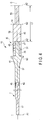
- FIG. 4 is a view showing a configuration of the vibrating body unit 10.
- a male screw section 46 is formed in a proximal portion of the ultrasonic probe 7.
- the ultrasonic probe 7 is connected to the distal direction side of the horn member 37 of the vibration generating unit 30.
- a female screw section 47 is formed in a distal portion of the rod-shaped member 45.
- the ultrasonic transducer 31 is attached to the transducer attachment section 38 in a state where it is sandwiched between the cross-sectional area change section 41 of the horn member 37 and the rod-shaped member 45. It is to be noted that the ultrasonic probe 7, the horn member 37, and the rod-shaped member 45 are made of materials having high transmissibility of the ultrasonic vibration such as Ti-6Al-4V.
- the ultrasonic vibration generated by the ultrasonic transducer 31 is transmitted to the ultrasonic probe 7 through the horn member 37. At this time, an amplitude of the ultrasonic vibration is increased in the cross-sectional area change section 41 of the horn member 37. In the ultrasonic probe 7, the ultrasonic vibration is transmitted from the proximal direction toward the distal direction. Further, the treatment section 17 provided in the distal portion of the ultrasonic probe 7 gives a treatment to a treated target such as a biological tissue by using the transmitted ultrasonic vibration. Furthermore, the ultrasonic vibration generated by the ultrasonic transducer 31 is transmitted to the rod-shaped member 45. Moreover, in the rod-shaped member 45, the ultrasonic vibration is transmitted from the distal direction toward the proximal direction. It is to be noted that the vibrating body unit 10 performs a longitudinal vibration having a vibrating direction and a transmitting direction parallel to the longitudinal axis C depending on the ultrasonic vibration.
- the vibrating body unit 10 vibrates at a resonance frequency Fr having antinode positions (e.g., A1 to A3) and node positions (e.g., N1 and N2).
- the distal end of the vibrating body unit 10 (the distal end of the ultrasonic probe 7) serves as the antinode position A1 of the ultrasonic vibration.
- the proximal end of the vibrating body unit 10 (the proximal end of the rod-shaped member 45) serves as the antinode position A3 of the ultrasonic vibration.
- the antinode position A1 is the most distal antinode position placed most distally among the antinode positions (e.g., A1 to A3) of the ultrasonic vibration.
- the antinode position A3 is the most proximal antinode position placed most proximally among the antinode positions (e.g., A1 to A3) of the ultrasonic vibration.
- the node position N1 of the ultrasonic vibration is placed in the cross-sectional area change region 41 of the horn member 37.
- the node position N1 is placed on the distal direction side with respect to the ultrasonic transducer 31.
- the proximal end of the horn member 37 serves as the antinode position A2 of the ultrasonic vibration.
- the antinode position A2 is placed on the proximal direction side with respect to the ultrasonic transducer 31.
- the antinode position which is closest to the ultrasonic transducer 31 is determined as a reference antinode position
- the antinode position A2 is the reference antinode position.
- the proximal end of the rod-shaped member 45 which is the proximal side transmitting section is placed at a position apart from the antinode position (the reference antinode position) A2 toward the proximal direction by an extending dimension L1 equal to a half wavelength (one time of the half wavelength) of the ultrasonic vibration at the resonance frequency Fr.
- the antinode position (the most proximal antinode position) A3 is apart from the antinode position (the reference antinode position) A2 by the extending dimension L1 equal to the half wavelength of the ultrasonic vibration in the axis parallel direction parallel to the longitudinal axis C.
- a cross-sectional area reducing section 51 is provided to the rod-shaped member 45, which is the proximal side vibration transmitting section, between the proximal end of the rod-shaped member 45 and the antinode position (the reference antinode position) A2 in the axis parallel direction parallel to the longitudinal axis C.
- a first transmitting region 52 is extended from the cross-sectional area reducing portion 51 toward the distal direction
- a second transmitting region 53 is extended from the cross-sectional area reducing section 51 toward the proximal direction.
- the cross-sectional area reducing section 51 is placed between the first transmitting region 52 and the second transmitting region 53 in the axis parallel direction.
- a cross-sectional area of the rod-shaped member 45 perpendicular to the longitudinal axis C is reduced due to the cross-sectional area reducing section 51 as compared with the first transmitting region 52.
- the cross-sectional area reducing section 51 is placed at the node position N2 of the ultrasonic vibration at the resonance frequency Fr.
- the cross-sectional area reducing section 51 serves as an amplitude increasing section configured to increase the amplitude of the ultrasonic vibration transmitted toward the proximal direction in the rod-shaped member 45.
- the stress caused by the ultrasonic vibration increases as compared with that at positions other than the node positions. Since the cross-sectional area of the rod-shaped member 45 perpendicular to the longitudinal axis C is reduced at the node position N2 where the stress caused by the ultrasonic vibration is large, a transformation ratio (an increase ratio) of the amplitude of the ultrasonic vibration in the cross-sectional area reducing section 51 rises. Since the transformation ratio of the amplitude of the ultrasonic vibration in the cross-sectional area reducing section 51 rises, a ratio of the amplitude in the second transmitting region 53 relative to the amplitude in the first transmitting region 52 increases.
- the node position N2 is closest to the antinode position (the reference antinode position) A2.
- the ultrasonic treatment apparatus 1 functions and Effects of the ultrasonic treatment apparatus 1 will now be described.
- the sheath 6, the ultrasonic probe 7, and the jaw 8 are inserted into a body cavity. Further, the treated target is placed between the jaw 8 and the treatment section 17.
- the movable handle 13 is closed relative to the fixed handle 12, the jaw 8 closes relative to the treatment section 17, and the treatment target is grasped between the jaw 8 and the treatment section 17.
- a supply operation is input by the supply operation input button 16 in a state where the treated target is griped, an electric current is supplied to the ultrasonic transducer 31 from the current supply section 21.
- the ultrasonic vibration is generated by the ultrasonic transducer 31, and the ultrasonic vibration is transmitted from the proximal direction toward the distal direction in the ultrasonic probe 7.
- the treatment section 17 uses the transmitted ultrasonic vibration to give a treatment, and the treated target is coagulated and incised at the same time as described above. At this time, the generated ultrasonic vibration is transmitted from the distal direction toward the proximal direction in the rod-shaped member 45.
- the ultrasonic probe (the distal side vibration transmitting section) 7 having the treatment section 17 provided therein is discarded, and the vibration generating unit 30 (the transducer unit 3) including the expensive piezoelectric elements 32A to 32D is reused.
- the ultrasonic probe 7 is replaced in accordance with each treatment.
- a type of a material forming the ultrasonic probe 7 differs depending on each ultrasonic probe.
- the content of aluminum differs depending on each ultrasonic probe 7.
- the Young's modulus Ea varies in accordance with each ultrasonic probe 7.
- the young's modulus Ea of the ultrasonic probe 7 affects the resonance frequency Fr of the vibrating body unit 10. Therefore, since the Young's modulus Ea varies in accordance with each ultrasonic probe 7, the resonance frequency Fr of the vibrating body unit 10 changes in accordance with a change in the ultrasonic probe 7 connected to the vibration generating unit 30. That is, the variation in the Young's modulus Ea according to each ultrasonic probe 7 causes a variation in the resonance frequency Fr of the vibrating body unit 10.
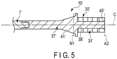
- FIG. 5 shows a vibrating body unit 10'.
- the vibrating body unit 10' like the vibrating body unit 10 according to the first embodiment, an ultrasonic probe 7', a horn member 37', and an ultrasonic transducer 31' are provided. Furthermore, the vibrating body unit 10' vibrates at a resonance frequency Fr having antinode positions (e.g., A1 and A2) and node positions (e.g., N1). Additionally, the antinode position A1 placed at a distal end of the ultrasonic probe 7' serves as the most distal antinode position.
- antinode position A1 placed at a distal end of the ultrasonic probe 7' serves as the most distal antinode position.
- the rod-shaped member (the proximal side vibration transmitting section) 45 is not provided, and a back mass 45'is provided instead.
- the ultrasonic transducer 31' is attached to a transducer attachment section 38' in a state where it is sandwiched between a cross-sectional area change section 41' of the horn member 37' and the back mass 45'.
- a position of a proximal end of the back mass 45' coincides with a position of a proximal end of the horn member 37' in the axis parallel direction parallel to the longitudinal axis C.
- the proximal end of the horn member 37' serves as the proximal end of the vibrating body unit 10' (the proximal end of the vibration generating unit 30').
- the antinode position A2 placed at the proximal end of the vibrating body unit 10' serves as the most proximal antinode position, and one antinode position A2 alone is placed on the proximal direction side with respect to the ultrasonic transducer 31'.
- a dimension in the axis parallel direction of the vibrating body unit 10' (the vibration generating unit 30') is smaller than that of the vibrating body unit 10 (the vibration generating unit 30) according to the first embodiment by a half wavelength of the ultrasonic vibration.
- the rod-shaped member (the proximal side vibration transmitting section) 45 is provided.
- the Young's modulus Ec of the rod-shaped member 45 affects the resonance frequency Fr of the vibrating body unit 10. That is, since the dimension in the axis parallel direction becomes larger than that in the case where the rod-shaped member 45 is not provided (the comparative example in FIG. 5 ) by the half wavelength of the ultrasonic vibration, the influence of the Young's modulus Eb of the vibration generating unit 30 on the resonance frequency Fr of the vibrating body unit 10 increases.
- the influence of the variation in the Young's modulus Ea according to each ultrasonic probe 7 on the resonance frequency Fr of the vibrating body unit 10 becomes smaller.
- the rod-shaped member 45 which is the proximal side vibration transmitting section
- an amplitude of the ultrasonic vibration transmitted from the distal direction toward the proximal direction is increased by the cross-sectional area reducing section 51.
- the amplitude of the ultrasonic vibration becomes large.
- the influence of the Young's modulus (E) on the resonance frequency (Fr) becomes considerable in a region where the amplitude of the ultrasonic vibration increases.
- the influence of the Young's modulus Ec of the rod-shaped member 45 on the resonance frequency Fr of the vibrating body unit 10 increases, and the influence of the Young's modulus Eb of the vibration generating unit 30 on the resonance frequency Fr of the vibrating body unit 10 further becomes significant.
- the influence of the variation in the Young's modulus Ea according to each ultrasonic probe 7 on the resonance frequency Fr of the vibrating body unit 10 is further lowered. Consequently, even if the variation in the Young's modulus Ea occurs in accordance with each ultrasonic probe 7 which is the distal side vibration transmitting section, the variation in the resonance frequency Fr of the vibrating body unit 10 can be reduced.
- the transformation ratio (the increase ratio) of the amplification of the ultrasonic vibration in the cross-sectional area reducing section 51 becomes high.
- the transformation ratio of the amplitude of the ultrasonic vibration in the cross-sectional area reducing section 51 becomes high, the amplitude in the second transmitting region 53 increases.
- the proximal end of the rod-shaped member 45 (the proximal end of the vibrating body unit 10) is placed at the position apart from the antinode position (the reference antinode position) A2 toward the proximal direction by the half wavelength of the ultrasonic vibration, but it is not restricted thereto.
- the proximal end of the rod-shaped member 45 may be placed at a position apart from the antinode position (the reference antinode position) A2 toward the proximal direction by an extending dimension L2 equal to one wavelength (two times of the half wavelength) of the ultrasonic vibration at the resonance frequency Fr as shown in FIG. 6 .
- the vibrating body unit 10 according to this modification vibrates at the resonance frequency Fr having the antinode positions (e.g., A1 to A4) and the node positions (e.g., N1 to N3).
- the antinode position A1 placed at the distal end of the ultrasonic probe 7 serves as the most distal antinode position
- the antinode position A4 placed at the proximal end of the rod-shaped member 45 serves as the most proximal antinode position
- the antinode position (the reference antinode position) A2 is placed at the proximal end of the horn member 37, and it is an antinode position that is closest to the ultrasonic transducer 31 among the antinode positions (e.g., A2 to A4) of the ultrasonic vibration placed on the proximal direction side with respect to the ultrasonic transducer 31.
- a dimension of the rod-shaped member 45 (the vibrating body unit 10) in the axis parallel direction parallel to the longitudinal axis C is longer than that in the first embodiment by the half wavelength.
- the cross-sectional area reducing section 51 which is an amplitude increasing section is provided at the node position N2 between the antinode position A2 and the antinode position A3.
- the second transmitting region 53 is extended toward the proximal direction until it reaches the antinode position (the most proximal antinode position) A4 through the antinode position A3.
- the node position N2 is closest to the antinode position (the reference antinode position) A2 among the node positions (e.g., N2 and N3) of the ultrasonic vibration placed on the proximal direction side with respect to the antinode position (the reference antinode position) A2.
- a dimension of the second transmitting region 53 in the axis parallel direction is longer than that in the first embodiment by the half wavelength.
- FIG. 7 A second embodiment according to the present invention will now be described with reference to FIG. 7 .
- the second embodiment is provided by modifying the configuration of the first embodiment as follows. It is to be noted that like reference numerals denote parts equal to those in the first embodiment to omit a description thereof.
- FIG. 7 is a view showing a configuration of a vibrating body unit 10 according to the second embodiment.
- the vibrating body unit 10 according to this embodiment vibrates at a resonance frequency Fr having antinode positions (e.g., A1 to A4) and node positions (e.g., N1 to N3).
- the antinode position A1 placed at a distal end of an ultrasonic probe 7 serves as the most distal antinode position
- the antinode position A4 placed at a proximal end of a rod-shaped member 45 serves as the most proximal antinode position.
- the antinode position (a reference antinode position) A2 is placed at a proximal end of a horn member 37, and it is an antinode position that is closest to an ultrasonic transducer 31 among the antinode positions (e.g., A2 to A4) of an ultrasonic vibration placed on the proximal direction side with respect to the ultrasonic transducer 31.
- a dimension of the rod-shaped member 45 (the transducer unit 10) in an axis parallel direction parallel to a longitudinal axis C is longer than that in the first embodiment by a half wavelength.
- a cross-sectional area reducing section 51 which is an amplitude increasing section is provided at the node position N2 between the antinode position A2 and the antinode position A3.
- the node position N2 is closest to the antinode position (the reference antinode position) A2 among the node positions (e.g., N2 and N3) of the ultrasonic vibration placed on the proximal direction side with respect to the antinode position (the reference antinode position) A2.
- a first extending region 55 is continuous on the proximal direction side of a second transmitting region 53.
- the first extending region 55 is placed on the proximal direction side with respect to the cross-sectional area reducing section 51 which is the amplitude increasing section.
- the second transmitting region 53 and the first extending region 55 are extended between the node position N2 and the antinode position A3.
- a second extending region 56 is provided on the proximal direction side of the first extending region 55 in the rod-shaped member 45.
- the second extending region 56 is extended from the antinode position A3 toward the proximal direction.
- the second extending region 56 is extended to the antinode position (the most proximal antinode position) A4 placed at the proximal end of the rod-shaped member 45 (the proximal end of the vibrating body unit 10).
- a cross-sectional area increasing section 57 is provided between the first extending region 55 and the second extending region 56 in the axis parallel direction that is parallel to the longitudinal axis C.
- a cross-sectional area of the rod-shaped member 45 perpendicular to the longitudinal axis C in the second extending region 56 is enlarged by the cross-sectional area increasing section 57 compared that in the first extending region 55. Consequently, a volume of the second extending region 56 increases.
- the antinode position (a cross section change antinode position) A3 is placed at the cross-sectional area increasing section 57.
- the antinode position (the cross section change antinode position) A3 is one of the antinode positions of the ultrasonic vibration placed between the cross-sectional area reducing section 51 as the amplitude increasing section and the proximal end of the rod-shaped member 45 in the axis parallel direction. Further, the antinode position (the cross section change antinode position) A3 is closest to the cross-sectional area reducing section (the amplitude increasing section) 51 among the antinode positions (e.g., A3 and A4) of the ultrasonic vibration placed on the proximal direction side with respect to the cross-sectional area reducing section 51.
- the ultrasonic vibration is transmitted from the first extending region 55 to the second extending region 56 without reducing its amplitude.
- the ultrasonic vibration is transmitted to the second extending region 56.
- the amplitude of the ultrasonic vibration increases.
- the second extending region 56 where the amplitude is large and the cross-sectional area perpendicular to the longitudinal axis C (i.e., a volume) is large is extended in the rod-shaped member 45 over the half wavelength of the ultrasonic vibration.
- the influence of the Young's modulus Ec of the rod-shaped member 45 on the resonance frequency Fr of the vibrating body unit 10 becomes prominent, and the influence of the Young's modulus Eb of the vibration generating unit 30 on the resonance frequency Fr of the vibrating body unit 10 becomes further considerable.
- an influence of a variation in the Young's modulus Ea according to each ultrasonic probe 7 on the resonance frequency Fr of the vibrating body unit 10 is further reduced. Consequently, even if the variation in the Young's modulus Ea occurs in accordance with each ultrasonic probe 7 which is a distal side vibration transmitting section, the variation in the resonance frequency Fr of the vibrating body unit 10 can be further effectively reduced.
- the antinode position (e.g., A3 and A4) of the ultrasonic vibration placed on the proximal direction side with respect to the cross-sectional area reducing section 51 the antinode position (the cross section change antinode position) A3 placed at the cross-sectional area increasing section 55 is closest to the cross-sectional area reducing section (the amplitude increasing section) 51.
- a dimension of the second extending region 56 in the axis parallel direction becomes large, and the volume of the second extending region 56 can be further increased.
- FIG. 8 is a view showing a relationship between the Young's modulus Ea of the ultrasonic probe 7 (7') and the resonance frequency Fr of the vibrating body unit 10 (10') in each of a comparative example, the first embodiment, and the second embodiment.
- a variation occurs in the Young's modulus Ea of the ultrasonic probe 7 (7') connected to the vibration generating unit 30 (30') between a maximum value Eamax and a minimum value Eamin.
- the resonance frequency Fr of the vibrating body unit 10' varies between a maximum value Fr1max and a minimum value Fr1min.
- the resonance frequency Fr of the vibrating body unit 10 varies between a maximum value Fr2max and a minimum value Fr2min, the variation in the resonance frequency Fr of the vibrating body unit 10 (10') is smaller than that in the comparative example.
- the resonance frequency Fr of the vibrating body unit 10 varies between a maximum value Fr3max and a minimum value Fr3min, and the variation in the resonance frequency Fr of the vibrating body unit 10 becomes further smaller than that in the first embodiment.
- an axis of abscissa represents the Young's modulus Ea of the ultrasonic probe 7 (7'), and an axis of ordinate represents the resonance frequency Fr of the vibrating body unit 10 (10').
- an inclination of a straight line is smaller than that in the comparative example.
- an inclination of a straight line is smaller than that in the first embodiment.
- a third embodiment according to the present invention will now be described with reference to FIG. 9 and FIG. 10 .
- the third embodiment is provided by modifying the configuration of the first embodiment as follows. It is to be noted that like reference numerals denote parts equal to those in the first embodiment to omit a description thereof.
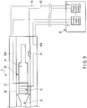
- FIG. 9 is a view showing a configuration of a transducer unit 3 and an electric power supply unit 20 according to this embodiment.
- a memory 61 which is a storage section is provided in a vibration generating unit 30. Vibration characteristics provided by ultrasonic vibration of the vibration generating unit 30 are stored in the memory 61. For example, information concerning the Young's modulus Eb of the vibration generating unit 30, a standard value of a resonance frequency Fr of a vibrating body unit 10, and others are stored in the memory 61.
- the Young's modulus Eb varies in accordance with each vibration generating unit 30 for the same reason as that of the ultrasonic probe 7. Even if an influence of a variation in the Young's modulus Ea of each ultrasonic probe 7 on the resonance frequency Fr of the vibrating body unit 10 is small, a vibration frequency Fr varies due to the variation in the Young's modulus Eb of each vibration generating unit 30. Thus, measurement of the resonance frequency Fr of the vibrating body unit 10 performed by a supply control section 22 of the electric power supply unit 20 becomes complicated.
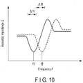
- FIG. 10 is a view showing a relationship between a frequency f of the ultrasonic vibration and an acoustic impedance Z.
- the acoustic impedance Z changes in accordance with a vibration state of the vibrating body unit 10.
- the acoustic impedance Z changes by a change in the frequency f of the ultrasonic vibration.
- the relationship between the frequency f of the ultrasonic vibration and the acoustic impedance Z changes in accordance with a change in the Young's modulus Eb of the vibration generating unit 30.
- the vibration generating unit 30 when one vibration generating unit 30 (the vibration generating unit 30 having the Young's modulus Eb1) is used in the vibrating body unit 10, the relationship between the frequency f of the ultrasonic vibration and the acoustic impedance Z changes as indicated by a solid line in FIG. 10 . Furthermore, when another vibration generating unit 30 (the vibration generating unit 30 having the Young's modulus Eb2) is used in the vibrating body unit 10, the relationship between the frequency f of the ultrasonic vibration and the acoustic impedance Z changes as indicated by a dotted line in FIG. 10 .
- the supply control section 22 controls an electric current supplied from a current supply section 21 to an ultrasonic transducer 31, and measures the resonance frequency Fr of the vibrating body unit 10 by performing a PLL (Phase Lock Loop) control. That is, a frequency f at which the acoustic impedance Z becomes minimum in a predetermined frequency domain (e.g., ⁇ f1 or ⁇ f2) of the ultrasonic vibration is detected as the resonance frequency Fr.
- a frequency f1 is detected as the resonance frequency Fr.
- the vibration generating unit 30 having the Young's modulus Eb2 is used in the vibrating body unit 10
- a frequency f2 is detected as the resonance frequency Fr.
- the memory 61 is connected to the supply control section 22 through an electrical signal line 62.
- the supply control section 22 controls a supply state of the electric current from the current supply section 21 based on vibration characteristics of the vibration generating unit 30 stored in the memory 61.
- the supply control section 22 measures the resonance frequency Fr of the vibrating body unit 10, in which the ultrasonic probe 7 is connected to the vibration generating unit 30, based on the vibration characteristics of the vibration generating unit 30.
- the supply control section 22 measures the resonance frequency Fr in a predetermined frequency domain (e.g., ⁇ f1 or ⁇ f2) near the resonance frequency Fr, but does not perform the measurement in frequency domains greatly deviating from the resonance frequency Fr.
- the measurement of the resonance frequency Fr of the vibrating body unit 10 is appropriately and readily performed by the supply control section 22 of the electric power supply unit 20, and the electric current is appropriately supplied from the current supply section 21 in the electric power supply unit 20 to the ultrasonic transducer 31.
- a predetermined frequency domain e.g., ⁇ f1 or ⁇ f2
- ultrasonic transducer 31 is provided in the vibration generating unit 30 in the foregoing embodiments and modification, but it is not restricted thereto.
- multiple (two in this modification) ultrasonic transducers 31A and 31B may be provided in the vibration generating unit 30 as shown in FIG. 11 .
- the ultrasonic transducers 31A and 31B are placed apart from each other in the axis parallel direction parallel to the longitudinal axis C.
- an antinode position A3 is the most proximal antinode position.
- the ultrasonic transducer 31B serves as the most proximal transducer placed most proximally among the ultrasonic transducer (e.g., 31A and 31B).
- An antinode position A2 is placed on the proximal direction side with respect to the ultrasonic transducer (the most proximal vibrator) 31B.
- the antinode position (a reference antinode position) A2 is an antinode position which is closest to the ultrasonic vibrator 31B among antinode positions (e.g., A2 and A3) of the ultrasonic vibration placed on the proximal direction side with respect to the ultrasonic transducer (the most proximal transducer) 31B.
- a proximal end of a rod-shaped member 45 (a proximal end of a vibrating body unit 10) is placed to be apart from the antinode position (the reference antinode position) A2 in the proximal direction by an extending dimension L3 equal to a half wavelength of the ultrasonic vibration at a resonance frequency Fr.
- a cross-sectional area reducing section 51 which is an amplitude increasing section is provided between the proximal end of the rod-shaped member 45 (the antinode position A3) and the antinode position (the reference antinode position) A2 in the axis parallel direction.
- a node position N2 of the ultrasonic vibration at the resonance frequency Fr is placed at the cross-sectional area reducing section 51.
- the treatment section 17 of the vibrating body unit 10 is used for ultrasonic incising-and-coagulation in the foregoing embodiment and modification, but it is not restricted thereto.
- a path section 65 may be formed in the vibrating body unit 10 along the longitudinal axis C as shown in FIG. 12 . Since the path section 65 is formed, the vibrating body unit 10 is formed into a hollow tubular shape. In this modification, a distal face 66 of the vibrating body unit 10 is used as a treatment section.
- a liquid such as a physiological saline
- the cavitation that has occurred is used to shatter and emulsify a treated target such as a biological tissue. Furthermore, the shattered and emulsified treated target is sucked and collected through the path section 65.
- the vibrating body unit 10 is used in an ultrasonic suction treatment.
- an influence of a variation in the Young's modulus Ea according to each ultrasonic probe 7 on the resonance frequency Fr of the vibrating body unit 10 is lowered.
- the proximal end of the proximal side vibration transmitting section (45) could be placed at a position part from the reference antinode position (A2) by the extending dimension (L1; L2) equal to an integral multiple of the half wavelength of the ultrasonic vibration.
- the reference antinode position (A2) is an antinode position closest to the ultrasonic transducer (31; 31B).
- the amplitude increasing section (51) that increases the amplitude of the ultrasonic vibration transmitted toward the proximal direction could be provided between the proximal end of the proximal side vibration transmitting section (45) and the reference antinode position (A2) in the axis parallel direction.
Landscapes
- Health & Medical Sciences (AREA)
- Engineering & Computer Science (AREA)
- Life Sciences & Earth Sciences (AREA)
- Biomedical Technology (AREA)
- Nuclear Medicine, Radiotherapy & Molecular Imaging (AREA)
- Animal Behavior & Ethology (AREA)
- General Health & Medical Sciences (AREA)
- Public Health (AREA)
- Veterinary Medicine (AREA)
- Radiology & Medical Imaging (AREA)
- Mechanical Engineering (AREA)
- Heart & Thoracic Surgery (AREA)
- Developmental Disabilities (AREA)
- Hospice & Palliative Care (AREA)
- Neurology (AREA)
- Psychiatry (AREA)
- Psychology (AREA)
- Social Psychology (AREA)
- Biophysics (AREA)
- Child & Adolescent Psychology (AREA)
- Surgical Instruments (AREA)
- Surgery (AREA)
- Dentistry (AREA)
- Medical Informatics (AREA)
- Molecular Biology (AREA)
Claims (8)
- Schwingungserzeugungseinheit (30), mit der ein distalseitiger Schwingungsübertragungsabschnitt (7) von einer Seite in distaler Richtung (C1) verbunden ist, wobei der distalseitige Schwingungsübertragungsabschnitt (7) einen Behandlungsabschnitt (17) umfasst, der konfiguriert ist, ein biologisches Gewebe zu behandeln, und der in einem distalen Teilbereich dieses bereitgestellt ist, und wobei die Schwingungserzeugungseinheit so konfiguriert ist, dass sie eine Ultraschallschwingung mit einer bestimmten Wellenlänge der Ultraschallschwingung erzeugt, wobei die Ultraschallschwingung an den distalseitigen Schwingungserzeugungsabschnitt (7) übertragen wird.
wobei die Schwingungserzeugungseinheit (30) umfasst:einen Ultraschallwandler (31), der ein piezoelektrisches Element (32A-32D) umfasst, das so konfiguriert ist, dass es die Ultraschallschwingung erzeugt, wenn ein elektrischer Strom zu diesem gespeist wird;einen Wandleranschlussabschnitt (38), an dem der Ultraschallwandler (31) angeschlossen ist;einen proximalseitigen Schwingungsübertragungsabschnitt (45), der sich von einem proximalen Ende des Ultraschallwandlers (31) hin zu einer proximalen Richtung (C2) entlang einer Längsachse (C) erstreckt, und wobei die vom Ultraschallwandler (31) erzeugte Ultraschallschwingung von der distalen Richtung hin zur proximalen Richtung übertragen wird, wobei ein proximales Ende des proximalseitigen Schwingungsübertragungsabschnitts (45) an einer Position platziert ist, die hin zur proximalen Richtung (C2) um eine Erstreckungsdimension (L1; L2) von einer Referenzbauchposition (A2) entfernt liegt, die einem ganzzahligen Vielfachen einer Hälfte der Wellenlänge der Ultraschallschwingung gleicht, wenn die Referenzbauchposition (A2) eine Bauchposition ist, die dem Ultraschallwandler (31) unter Bauchpositionen (A2, A3; A2-A4) der Ultraschallschwingung am nächsten gelegen ist, wie auf der Seite proximaler Richtung (C2) in Bezug auf den Ultraschallwandler (31) platziert; undeinen Amplitudenerhöhungsabschnitt (51), der zwischen dem proximalen Ende des proximalseitigen Schwingungsübertragungsabschnitts (45) und der Referenzbauchposition (A2) in einer Achsenparallelrichtung parallel zur Längsachse (C) bereitgestellt ist und der so konfiguriert ist, dass er eine Amplitude der hin zur proximalen Richtung (C2) übertragenen Ultraschallschwingung im proximalseitigen Schwingungsübertragungsabschnitt (45) erhöht, wobei der Amplitudenerhöhungsabschnitt (51) in einer Knotenposition (N2) platziert ist, die der Referenzbauchposition (A2) unter den Knotenpositionen (N2; N2, N3) der Ultraschallschwingung am nächsten gelegen ist, wie auf der Seite in proximaler Richtung (C2) in Bezug auf die Referenzbauchposition (A2) platziert. - Schwingungserzeugungseinheit (30) nach Anspruch 1,
dadurch gekennzeichnet, dass der proximalseitige Schwingungsübertragungsabschnitt (45) eine erste Übertragungsregion (52), die sich vom Amplitudenerhöhungsabschnitt (51) hin zu einer distalen Richtung (C1) erstreckt, und eine zweite Übertragungsregion (53), die sich vom Amplitudenerhöhungsabschnitt (51) hin zur proximalen Richtung (C2) erstreckt, umfasst, und
der Amplitudenerhöhungsabschnitt (51) einen Querschnittsflächenverringerungsabschnitt (51) umfasst, der zwischen der ersten Übertragungsregion (52) und der zweiten Übertragungsregion (53) in der Achsenparallelrichtung bereitgestellt ist und der so konfiguriert ist, dass er eine Querschnittsfläche des proximalseitigen Schwingungsübertragungsabschnitts (45) senkrecht zur Längsachse (C) in der zweiten Übertragungsregion (53) so verringert, dass sie kleiner als in der ersten Übertragungsregion (52) ist. - Schwingungserzeugungseinheit (30) nach Anspruch 1,
dadurch gekennzeichnet, dass der proximalseitige Schwingungsübertragungsabschnitt (45) umfasst:
eine erste Erstreckungsregion (55), die auf der Seite proximaler Richtung (C2) in Bezug auf den Amplitudenerhöhungsabschnitt (51) bereitgestellt ist;
eine zweite Erstreckungsregion (56), die auf der Seite proximaler Richtung (C2) in Bezug auf die erste Erstreckungsregion (55) bereitgestellt ist; und
einen Querschnittsflächenerhöhungsabschnitt (57), der zwischen der ersten Erstreckungsregion (55) und der zweiten Erstreckungsregion (56) in der Achsenparallelrichtung bereitgestellt ist und der so konfiguriert ist, dass er eine Querschnittsfläche des proximalseitigen Schwingungsübertragungsabschnitts (45) senkrecht zur Längsachse (C) in der zweiten Erstreckungsregion (56) so erhöht, dass sie höher als in der ersten Erstreckungsregion (55) ist, wobei der Querschnittsflächenerhöhungsabschnitt (57) in einer Querschnittsänderungsbauchposition (A3) platziert ist, die eine der Bauchpositionen (A3) der Ultraschallschwingung ist, die zwischen dem Amplitudenerhöhungsabschnitt (51) und dem proximalen Ende der proximalseitigen Schwingungsübertragungsregion (45) in Achsenparallelrichtung platziert ist. - Schwingungserzeugungseinheit (30) nach Anspruch 3,
dadurch gekennzeichnet, dass die Querschnittsänderungsbauchposition (A3) dem Amplitudenerhöhungsabschnitt (51) unter den Bauchpositionen (A3, A4) der Ultraschallschwingung am nächsten liegt, wie auf der Seite in proximaler Richtung (C2) in Bezug auf den Amplitudenerhöhungsabschnitt (51) platziert. - Schwingungserzeugungseinheit (30) nach Anspruch 1,
dadurch gekennzeichnet, dass der Ultraschallwandler (31) Ultraschallwandler (31A, 31B) sind, die in der Achsenparallelrichtung voneinander entfernt platziert sind, und
wenn der Ultraschallwandler, der unter den Ultraschallwandlern (31A, 31B) am proximalsten platziert ist, als proximalster Wandler (31B) ermittelt wird, die Referenzbauchposition (A2) eine Bauchposition ist, die dem proximalsten Wandler (31B) unter den Bauchpositionen (A2, A3) der Ultraschallschwingung am nächsten liegt, wie auf der Seite in proximaler Richtung (C2) in Bezug auf den proximalsten Wandler (31B) platziert. - Schwingungskörpereinheit (10), die dadurch gekennzeichnet ist, dass sie umfasst:die Schwingungserzeugungseinheit (30) nach Anspruch 1; undden distalseitigen Schwingungsübertragungsabschnitt (7), der sich in einem Teil auf der Seite in distaler Richtung (C1) der Schwingungserzeugungseinheit (30) entlang der Längsachse (C) erstreckt und der so konfiguriert ist, dass er die Ultraschallschwingung von der proximalen Richtung (C2) hin zu einer distalen Richtung (C1) überträgt, wobei der distalseitige Schwingungsübertragungsabschnitt (7) den Behandlungsabschnitt (17) umfasst, an den die Ultraschallschwingung im distalen Abschnitt dieses übertragen wird.
- Ultraschallbehandlungsvorrichtung (1), die dadurch gekennzeichnet ist, dass sie umfasst:die Schwingungskörpereinheit (10) nach Anspruch 6; undeine elektrische Energieversorgungseinheit (20), die einen Stromspeiseabschnitt (21) umfasst, der so konfiguriert ist, dass er einen elektrischen Strom zum Ultraschallwandler (31) speist.
- Ultraschallbehandlungsvorrichtung (1) nach Anspruch 7,
dadurch gekennzeichnet, dass die Schwingungserzeugungseinheit (30) einen Speicherabschnitt (61) umfasst, der so konfiguriert ist, dass er Schwingungscharakteristika speichert, die von der Ultraschallschwingung der Schwingungserzeugungseinheit (30) bereitgestellt werden, und
die elektrische Energieversorgungseinheit (20) einen Speisesteuerabschnitt (22) umfasst, der so konfiguriert ist, dass er einen Speisestatus des elektrischen Stroms aus dem Stromspeiseabschnitt (21) auf Basis der Schwingungscharakteristika der Schwingungserzeugungseinheit (30) steuert, die im Speicherabschnitt (61) gespeichert sind, und der so konfiguriert ist, dass er eine Resonanzfrequenz (f1; f2) der Schwingungskörpereinheit (10), in der der distalseitige Schwingungsübertragungsabschnitt (7) mit der Schwingungserzeugungseinheit (30) verbunden ist, auf Basis der Schwingungscharakteristika der Schwingungserzeugungseinheit (30) misst.
Applications Claiming Priority (2)
| Application Number | Priority Date | Filing Date | Title |
|---|---|---|---|
| JP2013237252 | 2013-11-15 | ||
| PCT/JP2014/078625 WO2015072326A1 (ja) | 2013-11-15 | 2014-10-28 | 振動発生ユニット、振動体ユニット及び超音波処置装置 |
Publications (3)
| Publication Number | Publication Date |
|---|---|
| EP3069676A1 EP3069676A1 (de) | 2016-09-21 |
| EP3069676A4 EP3069676A4 (de) | 2017-07-05 |
| EP3069676B1 true EP3069676B1 (de) | 2019-03-27 |
Family
ID=53057265
Family Applications (1)
| Application Number | Title | Priority Date | Filing Date |
|---|---|---|---|
| EP14861721.0A Active EP3069676B1 (de) | 2013-11-15 | 2014-10-28 | Schwingungserzeugungseinheit, schwingkörpereinheit und ultraschallbehandlungsvorrichtung |
Country Status (5)
| Country | Link |
|---|---|
| US (1) | US10046362B2 (de) |
| EP (1) | EP3069676B1 (de) |
| JP (1) | JP5865558B2 (de) |
| CN (1) | CN105722470B (de) |
| WO (1) | WO2015072326A1 (de) |
Families Citing this family (8)
| Publication number | Priority date | Publication date | Assignee | Title |
|---|---|---|---|---|
| CN107205764B (zh) | 2015-01-15 | 2020-07-10 | 奥林巴斯株式会社 | 振动体单元以及超声波探头 |
| JP6418330B2 (ja) * | 2015-08-04 | 2018-11-07 | 株式会社村田製作所 | 振動装置及びカメラ |
| CN108366810B (zh) * | 2015-12-07 | 2021-02-12 | 奥林巴斯株式会社 | 处置器具和处置部探头 |
| US11230758B2 (en) | 2016-09-16 | 2022-01-25 | Stryker European Holdings I, Llc | Tip for an ultrasonic surgical tool with case hardened cutting edges and method of making same |
| CN109792580B (zh) * | 2016-09-30 | 2020-11-10 | 奥林巴斯株式会社 | 超声波转换器及超声波转换器的制造方法 |
| CN109845292B (zh) * | 2016-10-14 | 2020-11-17 | 奥林巴斯株式会社 | 超声波转换器和超声波处置系统 |
| CN111479524B (zh) * | 2017-12-14 | 2023-07-04 | 奥林巴斯株式会社 | 超声波处置器具 |
| CN110575231B (zh) * | 2019-09-25 | 2021-02-19 | 哈尔滨优脉雷声科技有限责任公司 | 一种超声刀的刀杆结构及超声刀 |
Family Cites Families (16)
| Publication number | Priority date | Publication date | Assignee | Title |
|---|---|---|---|---|
| JPH0628209Y2 (ja) * | 1988-09-08 | 1994-08-03 | ティーディーケイ株式会社 | 超音波霧化器 |
| US5112300A (en) | 1990-04-03 | 1992-05-12 | Alcon Surgical, Inc. | Method and apparatus for controlling ultrasonic fragmentation of body tissue |
| US5516043A (en) * | 1994-06-30 | 1996-05-14 | Misonix Inc. | Ultrasonic atomizing device |
| FR2735412B1 (fr) * | 1995-06-19 | 1997-08-22 | Unir Ultra Propre Nutrition In | Dispositif de decoupage par ultrasons |
| US6077285A (en) * | 1998-06-29 | 2000-06-20 | Alcon Laboratories, Inc. | Torsional ultrasound handpiece |
| US6695781B2 (en) * | 1999-10-05 | 2004-02-24 | Omnisonics Medical Technologies, Inc. | Ultrasonic medical device for tissue remodeling |
| JP4020556B2 (ja) * | 2000-01-21 | 2007-12-12 | オリンパス株式会社 | 超音波駆動回路及び超音波手術装置 |
| JP2002035001A (ja) * | 2000-07-28 | 2002-02-05 | Olympus Optical Co Ltd | 超音波手術装置 |
| JP2002254044A (ja) * | 2001-02-27 | 2002-09-10 | Kao Corp | 超音波洗浄装置 |
| DE60141878D1 (de) | 2000-09-28 | 2010-06-02 | Kao Corp | Vorrichtung und Verfahren zum Reinigen mit Ultraschall |
| JP4129217B2 (ja) * | 2003-09-29 | 2008-08-06 | オリンパス株式会社 | 超音波手術システム、その異常検知方法および異常検知プログラム |
| US8226675B2 (en) * | 2007-03-22 | 2012-07-24 | Ethicon Endo-Surgery, Inc. | Surgical instruments |
| JP2008238390A (ja) * | 2007-03-23 | 2008-10-09 | Kazumasa Onishi | 超音波工具ホルダ |
| US7901423B2 (en) * | 2007-11-30 | 2011-03-08 | Ethicon Endo-Surgery, Inc. | Folded ultrasonic end effectors with increased active length |
| US8395299B2 (en) * | 2008-02-22 | 2013-03-12 | Piezo-Innocations | Ultrasonic torsional mode and longitudinal-torsional mode transducer system |
| CN103547380B (zh) | 2011-08-19 | 2015-10-07 | 奥林巴斯医疗株式会社 | 超声波产生装置及其制造方法、超声波处理装置及其制造方法 |
-
2014
- 2014-10-28 EP EP14861721.0A patent/EP3069676B1/de active Active
- 2014-10-28 JP JP2015527379A patent/JP5865558B2/ja not_active Expired - Fee Related
- 2014-10-28 CN CN201480062189.5A patent/CN105722470B/zh active Active
- 2014-10-28 WO PCT/JP2014/078625 patent/WO2015072326A1/ja not_active Ceased
-
2016
- 2016-03-18 US US15/074,192 patent/US10046362B2/en active Active
Non-Patent Citations (1)
| Title |
|---|
| None * |
Also Published As
| Publication number | Publication date |
|---|---|
| JP5865558B2 (ja) | 2016-02-17 |
| US10046362B2 (en) | 2018-08-14 |
| CN105722470B (zh) | 2018-02-27 |
| EP3069676A1 (de) | 2016-09-21 |
| CN105722470A (zh) | 2016-06-29 |
| WO2015072326A1 (ja) | 2015-05-21 |
| EP3069676A4 (de) | 2017-07-05 |
| US20160199881A1 (en) | 2016-07-14 |
| JPWO2015072326A1 (ja) | 2017-03-16 |
Similar Documents
| Publication | Publication Date | Title |
|---|---|---|
| US10046362B2 (en) | Vibration generating unit, vibrating body unit, and ultrasonic treatment apparatus | |
| US9693793B2 (en) | Ultrasonic probe and ultrasonic treatment instrument | |
| US8258886B2 (en) | System and method for improved start-up of self-oscillating electro-mechanical surgical devices | |
| EP2992847A1 (de) | Ultraschallbehandlungssystem | |
| JP5859509B2 (ja) | 超音波振動子システム | |
| US10328288B2 (en) | Vibration transmitting unit and ultrasonic treatment instrument | |
| US10743902B2 (en) | Vibrating body unit and ultrasonic probe | |
| US20170239497A1 (en) | Vibration generating unit, vibrating body unit and ultrasonic treatment instrument | |
| US20150196782A1 (en) | Ultrasonic probe and ultrasonic treatment device | |
| US10182963B2 (en) | Vibration generating unit, vibrating body unit and ultrasonic treatment instrument | |
| US10064641B2 (en) | Ultrasonic probe and ultrasonic treatment instrument | |
| WO2020152790A1 (ja) | 超音波処置具、及び超音波手術用装置 |
Legal Events
| Date | Code | Title | Description |
|---|---|---|---|
| PUAI | Public reference made under article 153(3) epc to a published international application that has entered the european phase |
Free format text: ORIGINAL CODE: 0009012 |
|
| 17P | Request for examination filed |
Effective date: 20160613 |
|
| AK | Designated contracting states |
Kind code of ref document: A1 Designated state(s): AL AT BE BG CH CY CZ DE DK EE ES FI FR GB GR HR HU IE IS IT LI LT LU LV MC MK MT NL NO PL PT RO RS SE SI SK SM TR |
|
| AX | Request for extension of the european patent |
Extension state: BA ME |
|
| RAP1 | Party data changed (applicant data changed or rights of an application transferred) |
Owner name: OLYMPUS CORPORATION |
|
| RAP1 | Party data changed (applicant data changed or rights of an application transferred) |
Owner name: OLYMPUS CORPORATION |
|
| DAX | Request for extension of the european patent (deleted) | ||
| A4 | Supplementary search report drawn up and despatched |
Effective date: 20170602 |
|
| RIC1 | Information provided on ipc code assigned before grant |
Ipc: A61N 1/04 20060101ALI20170529BHEP Ipc: A61B 17/32 20060101AFI20170529BHEP Ipc: A61B 18/00 20060101ALI20170529BHEP Ipc: A61B 17/22 20060101ALN20170529BHEP Ipc: B06B 1/06 20060101ALI20170529BHEP Ipc: A61B 17/00 20060101ALN20170529BHEP Ipc: B06B 3/00 20060101ALI20170529BHEP Ipc: A61N 1/36 20060101ALI20170529BHEP |
|
| REG | Reference to a national code |
Ref country code: DE Ref legal event code: R079 Ref document number: 602014043807 Country of ref document: DE Free format text: PREVIOUS MAIN CLASS: A61B0018000000 Ipc: A61B0017320000 |
|
| GRAP | Despatch of communication of intention to grant a patent |
Free format text: ORIGINAL CODE: EPIDOSNIGR1 |
|
| STAA | Information on the status of an ep patent application or granted ep patent |
Free format text: STATUS: GRANT OF PATENT IS INTENDED |
|
| RIC1 | Information provided on ipc code assigned before grant |
Ipc: A61B 17/00 20060101ALN20180921BHEP Ipc: A61N 7/00 20060101ALI20180921BHEP Ipc: B06B 3/00 20060101ALI20180921BHEP Ipc: A61B 18/00 20060101ALI20180921BHEP Ipc: B06B 1/06 20060101ALI20180921BHEP Ipc: A61B 17/32 20060101AFI20180921BHEP Ipc: A61B 17/22 20060101ALN20180921BHEP |
|
| INTG | Intention to grant announced |
Effective date: 20181016 |
|
| GRAS | Grant fee paid |
Free format text: ORIGINAL CODE: EPIDOSNIGR3 |
|
| GRAA | (expected) grant |
Free format text: ORIGINAL CODE: 0009210 |
|
| STAA | Information on the status of an ep patent application or granted ep patent |
Free format text: STATUS: THE PATENT HAS BEEN GRANTED |
|
| AK | Designated contracting states |
Kind code of ref document: B1 Designated state(s): AL AT BE BG CH CY CZ DE DK EE ES FI FR GB GR HR HU IE IS IT LI LT LU LV MC MK MT NL NO PL PT RO RS SE SI SK SM TR |
|
| REG | Reference to a national code |
Ref country code: GB Ref legal event code: FG4D |
|
| REG | Reference to a national code |
Ref country code: CH Ref legal event code: EP |
|
| REG | Reference to a national code |
Ref country code: AT Ref legal event code: REF Ref document number: 1112070 Country of ref document: AT Kind code of ref document: T Effective date: 20190415 |
|
| REG | Reference to a national code |
Ref country code: IE Ref legal event code: FG4D |
|
| REG | Reference to a national code |
Ref country code: DE Ref legal event code: R096 Ref document number: 602014043807 Country of ref document: DE |
|
| PG25 | Lapsed in a contracting state [announced via postgrant information from national office to epo] |
Ref country code: SE Free format text: LAPSE BECAUSE OF FAILURE TO SUBMIT A TRANSLATION OF THE DESCRIPTION OR TO PAY THE FEE WITHIN THE PRESCRIBED TIME-LIMIT Effective date: 20190327 Ref country code: LT Free format text: LAPSE BECAUSE OF FAILURE TO SUBMIT A TRANSLATION OF THE DESCRIPTION OR TO PAY THE FEE WITHIN THE PRESCRIBED TIME-LIMIT Effective date: 20190327 Ref country code: NO Free format text: LAPSE BECAUSE OF FAILURE TO SUBMIT A TRANSLATION OF THE DESCRIPTION OR TO PAY THE FEE WITHIN THE PRESCRIBED TIME-LIMIT Effective date: 20190627 Ref country code: FI Free format text: LAPSE BECAUSE OF FAILURE TO SUBMIT A TRANSLATION OF THE DESCRIPTION OR TO PAY THE FEE WITHIN THE PRESCRIBED TIME-LIMIT Effective date: 20190327 |
|
| REG | Reference to a national code |
Ref country code: NL Ref legal event code: MP Effective date: 20190327 |
|
| PG25 | Lapsed in a contracting state [announced via postgrant information from national office to epo] |
Ref country code: BG Free format text: LAPSE BECAUSE OF FAILURE TO SUBMIT A TRANSLATION OF THE DESCRIPTION OR TO PAY THE FEE WITHIN THE PRESCRIBED TIME-LIMIT Effective date: 20190627 Ref country code: GR Free format text: LAPSE BECAUSE OF FAILURE TO SUBMIT A TRANSLATION OF THE DESCRIPTION OR TO PAY THE FEE WITHIN THE PRESCRIBED TIME-LIMIT Effective date: 20190628 Ref country code: RS Free format text: LAPSE BECAUSE OF FAILURE TO SUBMIT A TRANSLATION OF THE DESCRIPTION OR TO PAY THE FEE WITHIN THE PRESCRIBED TIME-LIMIT Effective date: 20190327 Ref country code: NL Free format text: LAPSE BECAUSE OF FAILURE TO SUBMIT A TRANSLATION OF THE DESCRIPTION OR TO PAY THE FEE WITHIN THE PRESCRIBED TIME-LIMIT Effective date: 20190327 Ref country code: LV Free format text: LAPSE BECAUSE OF FAILURE TO SUBMIT A TRANSLATION OF THE DESCRIPTION OR TO PAY THE FEE WITHIN THE PRESCRIBED TIME-LIMIT Effective date: 20190327 Ref country code: HR Free format text: LAPSE BECAUSE OF FAILURE TO SUBMIT A TRANSLATION OF THE DESCRIPTION OR TO PAY THE FEE WITHIN THE PRESCRIBED TIME-LIMIT Effective date: 20190327 |
|
| REG | Reference to a national code |
Ref country code: AT Ref legal event code: MK05 Ref document number: 1112070 Country of ref document: AT Kind code of ref document: T Effective date: 20190327 |
|
| PG25 | Lapsed in a contracting state [announced via postgrant information from national office to epo] |
Ref country code: CZ Free format text: LAPSE BECAUSE OF FAILURE TO SUBMIT A TRANSLATION OF THE DESCRIPTION OR TO PAY THE FEE WITHIN THE PRESCRIBED TIME-LIMIT Effective date: 20190327 Ref country code: RO Free format text: LAPSE BECAUSE OF FAILURE TO SUBMIT A TRANSLATION OF THE DESCRIPTION OR TO PAY THE FEE WITHIN THE PRESCRIBED TIME-LIMIT Effective date: 20190327 Ref country code: IT Free format text: LAPSE BECAUSE OF FAILURE TO SUBMIT A TRANSLATION OF THE DESCRIPTION OR TO PAY THE FEE WITHIN THE PRESCRIBED TIME-LIMIT Effective date: 20190327 Ref country code: AL Free format text: LAPSE BECAUSE OF FAILURE TO SUBMIT A TRANSLATION OF THE DESCRIPTION OR TO PAY THE FEE WITHIN THE PRESCRIBED TIME-LIMIT Effective date: 20190327 Ref country code: SK Free format text: LAPSE BECAUSE OF FAILURE TO SUBMIT A TRANSLATION OF THE DESCRIPTION OR TO PAY THE FEE WITHIN THE PRESCRIBED TIME-LIMIT Effective date: 20190327 Ref country code: PT Free format text: LAPSE BECAUSE OF FAILURE TO SUBMIT A TRANSLATION OF THE DESCRIPTION OR TO PAY THE FEE WITHIN THE PRESCRIBED TIME-LIMIT Effective date: 20190727 Ref country code: ES Free format text: LAPSE BECAUSE OF FAILURE TO SUBMIT A TRANSLATION OF THE DESCRIPTION OR TO PAY THE FEE WITHIN THE PRESCRIBED TIME-LIMIT Effective date: 20190327 Ref country code: EE Free format text: LAPSE BECAUSE OF FAILURE TO SUBMIT A TRANSLATION OF THE DESCRIPTION OR TO PAY THE FEE WITHIN THE PRESCRIBED TIME-LIMIT Effective date: 20190327 |
|
| PG25 | Lapsed in a contracting state [announced via postgrant information from national office to epo] |
Ref country code: SM Free format text: LAPSE BECAUSE OF FAILURE TO SUBMIT A TRANSLATION OF THE DESCRIPTION OR TO PAY THE FEE WITHIN THE PRESCRIBED TIME-LIMIT Effective date: 20190327 Ref country code: PL Free format text: LAPSE BECAUSE OF FAILURE TO SUBMIT A TRANSLATION OF THE DESCRIPTION OR TO PAY THE FEE WITHIN THE PRESCRIBED TIME-LIMIT Effective date: 20190327 |
|
| PG25 | Lapsed in a contracting state [announced via postgrant information from national office to epo] |
Ref country code: IS Free format text: LAPSE BECAUSE OF FAILURE TO SUBMIT A TRANSLATION OF THE DESCRIPTION OR TO PAY THE FEE WITHIN THE PRESCRIBED TIME-LIMIT Effective date: 20190727 Ref country code: AT Free format text: LAPSE BECAUSE OF FAILURE TO SUBMIT A TRANSLATION OF THE DESCRIPTION OR TO PAY THE FEE WITHIN THE PRESCRIBED TIME-LIMIT Effective date: 20190327 |
|
| REG | Reference to a national code |
Ref country code: DE Ref legal event code: R097 Ref document number: 602014043807 Country of ref document: DE |
|
| PG25 | Lapsed in a contracting state [announced via postgrant information from national office to epo] |
Ref country code: DK Free format text: LAPSE BECAUSE OF FAILURE TO SUBMIT A TRANSLATION OF THE DESCRIPTION OR TO PAY THE FEE WITHIN THE PRESCRIBED TIME-LIMIT Effective date: 20190327 |
|
| PLBE | No opposition filed within time limit |
Free format text: ORIGINAL CODE: 0009261 |
|
| STAA | Information on the status of an ep patent application or granted ep patent |
Free format text: STATUS: NO OPPOSITION FILED WITHIN TIME LIMIT |
|
| PG25 | Lapsed in a contracting state [announced via postgrant information from national office to epo] |
Ref country code: SI Free format text: LAPSE BECAUSE OF FAILURE TO SUBMIT A TRANSLATION OF THE DESCRIPTION OR TO PAY THE FEE WITHIN THE PRESCRIBED TIME-LIMIT Effective date: 20190327 |
|
| 26N | No opposition filed |
Effective date: 20200103 |
|
| PG25 | Lapsed in a contracting state [announced via postgrant information from national office to epo] |
Ref country code: TR Free format text: LAPSE BECAUSE OF FAILURE TO SUBMIT A TRANSLATION OF THE DESCRIPTION OR TO PAY THE FEE WITHIN THE PRESCRIBED TIME-LIMIT Effective date: 20190327 |
|
| PG25 | Lapsed in a contracting state [announced via postgrant information from national office to epo] |
Ref country code: MC Free format text: LAPSE BECAUSE OF FAILURE TO SUBMIT A TRANSLATION OF THE DESCRIPTION OR TO PAY THE FEE WITHIN THE PRESCRIBED TIME-LIMIT Effective date: 20190327 |
|
| REG | Reference to a national code |
Ref country code: CH Ref legal event code: PL |
|
| PG25 | Lapsed in a contracting state [announced via postgrant information from national office to epo] |
Ref country code: CH Free format text: LAPSE BECAUSE OF NON-PAYMENT OF DUE FEES Effective date: 20191031 Ref country code: LU Free format text: LAPSE BECAUSE OF NON-PAYMENT OF DUE FEES Effective date: 20191028 Ref country code: LI Free format text: LAPSE BECAUSE OF NON-PAYMENT OF DUE FEES Effective date: 20191031 |
|
| REG | Reference to a national code |
Ref country code: BE Ref legal event code: MM Effective date: 20191031 |
|
| PG25 | Lapsed in a contracting state [announced via postgrant information from national office to epo] |
Ref country code: BE Free format text: LAPSE BECAUSE OF NON-PAYMENT OF DUE FEES Effective date: 20191031 |
|
| GBPC | Gb: european patent ceased through non-payment of renewal fee |
Effective date: 20191028 |
|
| PG25 | Lapsed in a contracting state [announced via postgrant information from national office to epo] |
Ref country code: FR Free format text: LAPSE BECAUSE OF NON-PAYMENT OF DUE FEES Effective date: 20191031 Ref country code: IE Free format text: LAPSE BECAUSE OF NON-PAYMENT OF DUE FEES Effective date: 20191028 Ref country code: GB Free format text: LAPSE BECAUSE OF NON-PAYMENT OF DUE FEES Effective date: 20191028 |
|
| PG25 | Lapsed in a contracting state [announced via postgrant information from national office to epo] |
Ref country code: CY Free format text: LAPSE BECAUSE OF FAILURE TO SUBMIT A TRANSLATION OF THE DESCRIPTION OR TO PAY THE FEE WITHIN THE PRESCRIBED TIME-LIMIT Effective date: 20190327 |
|
| PG25 | Lapsed in a contracting state [announced via postgrant information from national office to epo] |
Ref country code: HU Free format text: LAPSE BECAUSE OF FAILURE TO SUBMIT A TRANSLATION OF THE DESCRIPTION OR TO PAY THE FEE WITHIN THE PRESCRIBED TIME-LIMIT; INVALID AB INITIO Effective date: 20141028 Ref country code: MT Free format text: LAPSE BECAUSE OF FAILURE TO SUBMIT A TRANSLATION OF THE DESCRIPTION OR TO PAY THE FEE WITHIN THE PRESCRIBED TIME-LIMIT Effective date: 20190327 |
|
| PG25 | Lapsed in a contracting state [announced via postgrant information from national office to epo] |
Ref country code: MK Free format text: LAPSE BECAUSE OF FAILURE TO SUBMIT A TRANSLATION OF THE DESCRIPTION OR TO PAY THE FEE WITHIN THE PRESCRIBED TIME-LIMIT Effective date: 20190327 |
|
| P01 | Opt-out of the competence of the unified patent court (upc) registered |
Effective date: 20230528 |
|
| PGFP | Annual fee paid to national office [announced via postgrant information from national office to epo] |
Ref country code: DE Payment date: 20251021 Year of fee payment: 12 |