EP3069760A1 - Implantierbare elektromedizinische vorrichtung - Google Patents
Implantierbare elektromedizinische vorrichtung Download PDFInfo
- Publication number
- EP3069760A1 EP3069760A1 EP16158393.5A EP16158393A EP3069760A1 EP 3069760 A1 EP3069760 A1 EP 3069760A1 EP 16158393 A EP16158393 A EP 16158393A EP 3069760 A1 EP3069760 A1 EP 3069760A1
- Authority
- EP
- European Patent Office
- Prior art keywords
- peripheral flange
- conductor element
- base body
- ceramic base
- electrode
- Prior art date
- Legal status (The legal status is an assumption and is not a legal conclusion. Google has not performed a legal analysis and makes no representation as to the accuracy of the status listed.)
- Granted
Links
Images

Classifications
-
- A—HUMAN NECESSITIES
- A61—MEDICAL OR VETERINARY SCIENCE; HYGIENE
- A61N—ELECTROTHERAPY; MAGNETOTHERAPY; RADIATION THERAPY; ULTRASOUND THERAPY
- A61N1/00—Electrotherapy; Circuits therefor
- A61N1/18—Applying electric currents by contact electrodes
- A61N1/32—Applying electric currents by contact electrodes alternating or intermittent currents
- A61N1/36—Applying electric currents by contact electrodes alternating or intermittent currents for stimulation
- A61N1/372—Arrangements in connection with the implantation of stimulators
- A61N1/375—Constructional arrangements, e.g. casings
- A61N1/3752—Details of casing-lead connections
- A61N1/3754—Feedthroughs
-
- A—HUMAN NECESSITIES
- A61—MEDICAL OR VETERINARY SCIENCE; HYGIENE
- A61N—ELECTROTHERAPY; MAGNETOTHERAPY; RADIATION THERAPY; ULTRASOUND THERAPY
- A61N1/00—Electrotherapy; Circuits therefor
- A61N1/18—Applying electric currents by contact electrodes
- A61N1/32—Applying electric currents by contact electrodes alternating or intermittent currents
- A61N1/36—Applying electric currents by contact electrodes alternating or intermittent currents for stimulation
- A61N1/362—Heart stimulators
-
- A—HUMAN NECESSITIES
- A61—MEDICAL OR VETERINARY SCIENCE; HYGIENE
- A61N—ELECTROTHERAPY; MAGNETOTHERAPY; RADIATION THERAPY; ULTRASOUND THERAPY
- A61N1/00—Electrotherapy; Circuits therefor
- A61N1/18—Applying electric currents by contact electrodes
- A61N1/32—Applying electric currents by contact electrodes alternating or intermittent currents
- A61N1/38—Applying electric currents by contact electrodes alternating or intermittent currents for producing shock effects
- A61N1/39—Heart defibrillators
- A61N1/3956—Implantable devices for applying electric shocks to the heart, e.g. for cardioversion
-
- B—PERFORMING OPERATIONS; TRANSPORTING
- B22—CASTING; POWDER METALLURGY
- B22F—WORKING METALLIC POWDER; MANUFACTURE OF ARTICLES FROM METALLIC POWDER; MAKING METALLIC POWDER; APPARATUS OR DEVICES SPECIALLY ADAPTED FOR METALLIC POWDER
- B22F3/00—Manufacture of workpieces or articles from metallic powder characterised by the manner of compacting or sintering; Apparatus specially adapted therefor ; Presses and furnaces
- B22F3/10—Sintering only
-
- B—PERFORMING OPERATIONS; TRANSPORTING
- B22—CASTING; POWDER METALLURGY
- B22F—WORKING METALLIC POWDER; MANUFACTURE OF ARTICLES FROM METALLIC POWDER; MAKING METALLIC POWDER; APPARATUS OR DEVICES SPECIALLY ADAPTED FOR METALLIC POWDER
- B22F5/00—Manufacture of workpieces or articles from metallic powder characterised by the special shape of the product
-
- B—PERFORMING OPERATIONS; TRANSPORTING
- B22—CASTING; POWDER METALLURGY
- B22F—WORKING METALLIC POWDER; MANUFACTURE OF ARTICLES FROM METALLIC POWDER; MAKING METALLIC POWDER; APPARATUS OR DEVICES SPECIALLY ADAPTED FOR METALLIC POWDER
- B22F7/00—Manufacture of composite layers, workpieces, or articles, comprising metallic powder, by sintering the powder, with or without compacting wherein at least one part is obtained by sintering or compression
- B22F7/06—Manufacture of composite layers, workpieces, or articles, comprising metallic powder, by sintering the powder, with or without compacting wherein at least one part is obtained by sintering or compression of composite workpieces or articles from parts, e.g. to form tipped tools
-
- A—HUMAN NECESSITIES
- A61—MEDICAL OR VETERINARY SCIENCE; HYGIENE
- A61N—ELECTROTHERAPY; MAGNETOTHERAPY; RADIATION THERAPY; ULTRASOUND THERAPY
- A61N1/00—Electrotherapy; Circuits therefor
- A61N1/18—Applying electric currents by contact electrodes
- A61N1/32—Applying electric currents by contact electrodes alternating or intermittent currents
- A61N1/36—Applying electric currents by contact electrodes alternating or intermittent currents for stimulation
- A61N1/372—Arrangements in connection with the implantation of stimulators
- A61N1/375—Constructional arrangements, e.g. casings
- A61N1/3756—Casings with electrodes thereon, e.g. leadless stimulators
Definitions
- the invention relates to an implantable electromedical device, comprising an enclosure part which accommodates an electronic or electrical functional unit, an electrode arranged on the outside of the enclosure part or a conduit connection and a passage which encloses an opening of the enclosure part and at least one the electrode or the conduit connection accommodating the functional unit connecting metallic conductor element and has a metallic peripheral flange.
- Such devices are in particular as pacemakers or implantable cardioverter (especially defibrillators) for a long time in mass use.
- this may also be a less complex device, such as an electrode or sensor line or a cochlear implant act.
- Electrodes or connections for at least one electrode line are provided directly on the device, in the distal end section the electrodes for pulse transmission the tissues are attached.
- the electronic / electrical functional units inside the unit are to be connected in a manner with the outer electrodes or electrode lead terminals, which ensures an absolutely and permanently reliable function under the special conditions of the implanted state.
- feedthroughs are known, whose base and insulating body consists essentially of ceramic or glass, and multilayer or multi-part structures have been developed using metal or metal oxides and are used.
- Such known bushings largely meet the demands placed on them.
- the invention is based on the object to provide an improved implantable electromedical device, which is inexpensive to produce and highly reliable.
- the invention is based on the idea of using the MIM technology for the metallic components (pin) and flange of a bushing to produce a bushing in a single process step.
- the process allows both the outboard flange and the inboard pin to undergo a strong mechanical-chemical bond with the insulator through shrinkage due to a particular geometry.
- the shrinkage behavior of the components used can be coordinated by pre-sintering (e.g., browning) or by a particular composition of the spray powder (fraction of binder) for co-sintering. This also applies to the physicochemical contribution of the process to creating a firm connection of the individual parts.
- the peripheral flange and the or each conductor element are designed as sintered parts formed of the same material by metal powder injection molding.
- an extension which is arranged directly on a device-inner and a device-outer surface or a recess of the ceramic base housing arranged there is provided on the or each conductor element. More specifically, projections are additionally provided on the peripheral flange on a device-inner and a device-outer surface or arranged there a recess of the ceramic base housing.
- the pressing is done in the process by cooling the hot-formed parts peripheral flange and conductor element, which leads to a contraction of the same in the thickness direction of the ceramic body or to a contraction of the peripheral flange in the direction normal to the boundary surface peripheral flange ceramic shell surface.
- the or each extension is annular or disc-shaped surrounding the inner circumference of the peripheral flange or the outer circumference of the or each conductor element formed.
- the ceramic base body is formed substantially of alumina ceramic; In principle, however, other technical ceramics can be used.
- the peripheral flange and / or the or each conductor element are preferably formed from titanium or a titanium alloy. In principle, however, it is also possible to use related metals such as molybdenum, tantalum, tungsten, vanadium, zirconium or iridium and alloys thereof or nickel or palladium or their alloys.
- the method will still include the later step of connecting the bushing to the casing, in particular by welding or gluing or shrinking the casing to the peripheral flange of the bushing.
- the specific way of mounting the bushing depends on the type of device in which it is used.
- the device is designed as an electrostimulation device, in particular cardiac pacemaker or cardioverter, wherein the envelope part designed as a device housing and the electrode or the lead terminal is arranged on a relative to the device housing head part and arranged the implementation between the device housing and the head part is.
- an electrode line wherein in particular the conductor element forms an electrode in its outer cover portion at the same time.
- Fig. 1 1 shows a pacemaker 1 with a pacemaker housing 3 and a header 5, in the interior of which a printed circuit board (PCB) 7 is arranged in addition to other electronic components and an electrode line 9 is connected to its line connection (not shown) in the header.
- a provided between the device housing 3 and header 5 implementation 11 includes a plurality of pins 13. The pins are inserted at one end through a corresponding hole in the circuit board and soldered to this soft.
- Fig. 2 shows a perspective view of an embodiment of the bushing 11, the constituents of which are next to the terminal pins 13, a ceramic base body (insulator) 15 and a metallic peripheral flange 17. In the peripheral flange 17, a ground pin 19 is inserted.
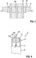
- Fig. 3 shows the structure in a longitudinal sectional view.
- the ceramic base body 15 is in the example of an alumina ceramic, but can be prefabricated as well as a zirconia ceramic or other biocompatible ceramic material by conventional techniques with the exception of adapted to the shape of the conductor elements (pins) 13 openings. On or in the ceramic base body 15 of the peripheral flange 17 and the conductor elements by means of metal powder injection molding (MIM process) hermetically sealed or molded.
- MIM process metal powder injection molding
- a frictionally tight connection between the parts is created by a shrinkage of the metal parts in this process.
- the pins 13 are provided on both surfaces of the ceramic base body 15 each with annular thickenings 13 a. These press each other in the MIM process as a result of the length shrinkage of the pins against the adjacent inner annular surface of the ceramic base body 15 and connect to him both non-positively and by a physico-chemical interface process.
- An analogue process is running on Inner circumference of the peripheral flange 17 relative to the outer periphery of the ceramic base body 15 from.
- the pins 13 and the peripheral flange 17 may be formed of the same material (such as a titanium alloy) in a common MIM process flow, but it is also possible to manufacture them from different materials in successive processes. After debinding and sintering, the pins can be completed with additional parts (sleeves or pads) or suitable coatings for the connection of further elements, which are not shown in the figures, but are known per se to those skilled in the art.
- the peripheral flange 17 can in the usual way with a correspondingly extending opening edge of the housing 3 ( Fig. 1 ), such as by a laser welding process.
- Fig. 4 shows as a further embodiment, the distal end of an electrode line 1 ', in which a bushing 11' forms the line end.
- the bushing 11 ' comprises a single terminal pin 13', a ceramic base body 15 'and a peripheral flange 17' and is shrunk or glued into the free end of the cable sheath 3 '.
- the connecting pin 13 ' is in its outer portion at the same time the outer functional element (electrode) of the electrode line and at its proximal end in a conventional manner (such as by soldering) connected to an electronic functional unit 7'.
Landscapes
- Health & Medical Sciences (AREA)
- Engineering & Computer Science (AREA)
- Animal Behavior & Ethology (AREA)
- General Health & Medical Sciences (AREA)
- Biomedical Technology (AREA)
- Nuclear Medicine, Radiotherapy & Molecular Imaging (AREA)
- Radiology & Medical Imaging (AREA)
- Life Sciences & Earth Sciences (AREA)
- Veterinary Medicine (AREA)
- Public Health (AREA)
- Cardiology (AREA)
- Manufacturing & Machinery (AREA)
- Mechanical Engineering (AREA)
- Heart & Thoracic Surgery (AREA)
- Chemical & Material Sciences (AREA)
- Composite Materials (AREA)
- Materials Engineering (AREA)
- Electrotherapy Devices (AREA)
Abstract
Description
- Die Erfindung betrifft eine implantierbare elektromedizinische Vorrichtung, umfassend ein Umhüllungsteil, das eine elektronische oder elektrische Funktionseinheit aufnimmt, eine an der Außenseite des Umhüllungsteils angeordnete Elektrode oder einen Leitungsanschluss und eine Durchführung, die eine Öffnung des Umhüllungsteils umschließt und mindestens ein die Elektrode oder den Leitungsanschluss mit der Funktionseinheit verbindendes metallisches Leiterelement aufnimmt und einen metallischen Umfangsflansch hat.
- Derartige Geräte sind insbesondere als Herzschrittmacher oder implantierbare Kardioverter (speziell Defibrillatoren) seit langem in massenhaftem Einsatz. Es kann sich hierbei aber auch um eine weniger komplexe Vorrichtung, wie etwa eine Elektroden- oder Sensorleitung oder auch ein Cochlearimplantat, handeln.
- Die meisten praktisch bedeutsamen implantierbaren elektromedizinischen Geräte sind dazu vorgesehen, über geeignet platzierte Elektroden elektrische Impulse an reizbares Körpergewebe abzugeben. Um diese Funktion auszuführen, sind im Gehäuse des Gerätes elektronische/elektrische Funktionseinheiten zur Erzeugung der Impulse und zur geeigneten Steuerung der Impulserzeugung untergebracht, und außen am Gerät sind unmittelbar Elektroden oder Anschlüsse für mindestens eine Elektrodenleitung vorgesehen, in deren distalem Endabschnitt die Elektroden zur Impulsübertragung an das Gewebe angebracht sind. Die elektronischen/elektrischen Funktionseinheiten im Geräteinneren sind in einer Weise mit den äußeren Elektroden oder Elektrodenleitungsanschlüssen zu verbinden, die unter den speziellen Bedingungen des implantierten Zustandes eine absolut und dauerhaft verlässliche Funktion gewährleistet.
- Bekannt sind insbesondere Durchführungen, deren Grund- und Isolationskörper im Wesentlichen aus Keramik oder Glas besteht, wobei auch mehrschichtige bzw. mehrteilige Aufbauten unter Einsatz von Metallen oder Metalloxiden entwickelt wurden und eingesetzt werden. Derartige bekannte Durchführungen erfüllen weitgehend die an sie gestellten Anforderungen.
- Die bekannten Durchführungs-Aufbauten sind jedoch in der Herstellung relativ arbeits- und somit kostenaufwändig. Insbesondere sind mehrere Arbeits- und Prozessschritte erforderlich, es ist ein aufwändiges Fügen von mehreren Einzelkomponenten und teilweise eine Vorbehandlung derselben (z.B. Reinigung, Oberflächenvorbehandlung, Herstellung der Lötbarkeit) erforderlich, und die Prozesse müssen dementsprechend auch mehrere Prüfschritte umfassen.
- Aus der
DE 10 2009 003 958 B4 ist ein Verfahren zur Herstellung einer Durchführung eines Gerätes bekannt, bei dem ein metallischer Leiter mit einer isolierenden Ummantelung (speziell aus einem Oxid des Leiters) versehen und auf diesen isolierten Leiter ein Flansch mittels Metall-Pulverspritzgießen mit anschließender Abkühlung aufgeschrumpft wird. Aus derEP 1 820 534 A2 ist es auch bekannt, einen Umfangsflansch um eine ansonsten aus mehreren Teilen vormontierte Durchführung durch das Verfahren des Metall-Pulverspritzgießens zu erzeugen. Aus derUS 2008/0209723 A1 ist es auch bekannt, ein Keramikbauteil in der Verarbeitungsstufe des sogenannten Bräunlings oder Grünlings auf einen metallischen Leiterstift aufzuschrumpfen. - Aus der
US 2012/0319319 A1 ist es bekannt, Durchführungen für hermetisch abgedichtete Gerätegehäuse zu erzeugen, indem sowohl ein Isolationskörper als auch ein Leiter, der diesen durchläuft, mittels eines Pulverspritzgießverfahrens gebildet werden. - Der Erfindung liegt die Aufgabe zu Grunde, ein verbessertes implantierbares elektromedizinisches Gerät bereitzustellen, welches kostengünstig herstellbar und hochgradig zuverlässig ist.
- Diese Aufgabe wird in ihrem Vorrichtungsaspekt durch ein Gerät mit den Merkmalen des Anspruchs 1 und in ihrem Verfahrensaspekt durch ein Verfahren mit den Merkmalen des Anspruchs 10 gelöst. Zweckmäßige Fortbildungen des Erfindungsgedankens sind Gegenstand der abhängigen Ansprüche.
- Die Erfindung geht von dem Gedanken eines Einsatzes der MIM-Technologie für die metallischen Komponenten (Pin) und Flansch einer Durchführung zur Herstellung einer Durchführung in einem Prozessschritt aus. Der Prozess lässt zu, dass sowohl der außen liegende Flansch als auch der innen liegende Pin durch eine bestimmte Geometrie beim Schrumpfen eine feste mechanisch-chemische Verbindung mit dem Isolator eingehen. Das Schrumpfverhalten der eingesetzten Komponenten kann durch Vorsintern (z.B. Bräunling) oder durch eine bestimmte Zusammensetzung des Spritzpulvers (Anteil des Binders) für das gemeinsame Sintern aufeinander abgestimmt werden. Dies gilt auch für den physiko-chemischen Beitrag des Verfahrens zur Schaffung einer festen Verbindung der einzelnen Teile.
- Das vorgeschlagene Verfahren bietet, zumindest in bevorzugten Ausführungen, einen oder mehrere der folgenden Vorteile:
- hohe Wiederholgenauigkeit + Positioniergenauigkeit
- kein gesonderter Fügeprozess für Einzelkomponenten erforderlich
- kein Lot erforderlich
- kostengünstig bei hohen Stückzahlen
- geringe Bestückungsaufwand
- starke Reduktion der Fertigungshilfsmittel
- weniger Prüf- und Vorbehandlungsschritte (Prozessschritte) notwendig.
- In einer Ausführung der Erfindung sind der Umfangsflansch und das oder jedes Leiterelement als materialeinheitlich durch Metall-Pulverspritzgießen gebildete Sinterteile ausgeführt. Grundsätzlich ist es auch möglich, den Umfangsflansch und die Leiterelemente aus verschiedenen Materialien, aber jeweils durch das erwähnte Verfahren, zu bilden. Dies erfordert jedoch eine komplexere Prozessführung und ist daher aus derzeitiger Sicht weniger bevorzugt.
- In einer vorteilhaften Ausgestaltung ist an dem oder jedem Leiterelement je ein derart direkt an einer vorrichtungs-inneren und einer vorrichtungs-äußeren Oberfläche oder einer dort angeordneten Ausnehmung des Keramik-Grundgehäuses angeordneter Fortsatz vorgesehen. Noch spezieller sind zusätzlich am Umfangsflansch an einer vorrichtungs-inneren und einer vorrichtungs-äußeren Oberfläche oder einer dort angeordneten Ausnehmung des Keramik-Grundgehäuses angeordnete Fortsätze vorgesehen.
- Das Anpressen geschieht im Prozess durch das Abkühlen der heiß geformten Teile Umfangsflansch und Leiterelement, welches zu einem Zusammenziehen derselben in Dickenrichtung des Keramik-Grundkörpers bzw. zu einem Zusammenziehen des Umfangsflansches in der Richtung normal zur Grenzfläche Umfangsflansch-Keramikmantelfläche führt. In weiter vorteilhafter Ausgestaltung ist hierbei der oder jeder Fortsatz ring- oder scheibenförmig den Innenumfang des Umfangsflansches bzw. den Außenumfang des oder jedes Leiterelements umgebend ausgebildet. Hierdurch wird die jeweilige Grenzfläche mit dem Keramik-Grundkörper vollumfänglich abgedeckt und somit insbesondere ohne zusätzliche Hilfsmittel hermetisch dicht.
- In einer weiteren Ausführung der Erfindung ist der Keramik-Grundkörper im Wesentlichen aus Aluminiumoxid-Keramik gebildet; grundsätzlich sind aber auch andere technische Keramiken einsetzbar. Des Weiteren sind bevorzugt der Umfangsflansch und/oder das oder jedes Leiterelement aus Titan oder einer Titanlegierung gebildet. Grundsätzlich können aber auch verwandte Metalle, wie Molybdän, Tantal, Wolfram, Vanadium, Zirkon oder Iridium und Legierungen derselben oder Nickel oder Palladium oder deren Legierungen zum Einsatz kommen.
- Unter verfahrenstechnischen Gesichtspunkten umfasst eine zweckmäßige Ausführung der Erfindung die Schritte:
- Bilden des Keramik-Grundkörpers,
- Bereitstellen einer Pulverspritzgussform,
- Einlegen des Keramik-Grundkörpers in teilweise oder vollständig vorgesintertem Zustand in die Pulverspritzgussform,
- Einspritzen von Spritzgießmaterial zur Bildung des Umfangsflansches und des oder jedes Leiterelementes in die Pulverspritzgussform,
- Sintern/Wärmebehandlung der Pulverspritzgussform mit dem darin aufgenommenen Material zum Entbinden, Ausgasen und Schrumpfen des den Umfangsflansch und das oder jedes Leiterelement bildenden Materials und
- Entnehmen der Durchführung aus der Pulverspritzgussform.
- Üblicherweise wird das Verfahren noch den späteren Schritt eines Verbindens der Durchführung mit der Umhüllung, insbesondere durch Verschweißen oder Verkleben oder Aufschrumpfen der Umhüllung auf den Umfangsflansch der Durchführung umfassen. Die konkrete Art der Montage der Durchführung hängt selbstverständlich vom Typ des Gerätes ab, in dem sie eingesetzt wird.
- In einer ersten wichtigen Anwendung der Erfindung ist das Gerät ausgebildet als Elektrostimulationsgerät, insbesondere Herzschrittmacher oder Kardioverter, wobei das Umhüllungsteil als Gerätegehäuse ausgestaltet und die Elektrode oder der Leitungsanschluss an einem gegenüber dem Gerätegehäuse separaten Kopfteil angeordnet ist und die Durchführung zwischen dem Gerätegehäuse und dem Kopfteil angeordnet ist. In einer weiteren wichtigen Anwendung handelt es sich um eine Elektrodenleitung, wobei insbesondere das Leiterelement in seinem umhüllungs-äußeren Abschnitt zugleich eine Elektrode bildet.
- Vorteile und Zweckmäßigkeiten der Erfindung ergeben sich im Übrigen aus der Beschreibung von Ausführungsbeispielen anhand der Figuren. Von diesen zeigen:
- Fig. 1
- eine schematische, teilweise geschnittene Darstellung eines implantierbaren elekt-romedizinischen Geräts,
- Fig. 2
- eine perspektivische Darstellung einer beispielhaften Durchführung des Gerätes nach
Fig. 1 , - Fig. 3
- eine Längsschnittdarstellung dieser beispielhaften Durchführung und
- Fig. 4
- eine Längsschnittdarstellung eines weiteren Ausführungsbeispiels der Erfindung.
-
Fig. 1 zeigt einen Herzschrittmacher 1 mit einem Schrittmachergehäuse 3 und einem Kopfteil (Header) 5, in dessen Innerem neben anderen elektronischen Komponenten eine Leiterplatte (PCB) 7 angeordnet und mit dessen im Header angeordneten (nicht gezeigten) Leitungsanschluss eine Elektrodenleitung 9 verbunden ist. Eine zwischen Gerätegehäuse 3 und Header 5 vorgesehene Durchführung 11 umfasst eine Mehrzahl von Anschlussstiften 13. Die Anschlussstifte sind an einem Ende durch eine entsprechende Bohrung in der Leiterplatte gesteckt und mit dieser weich verlötet. -
Fig. 2 zeigt in einer perspektivischen Darstellung ein Ausführungsbeispiel der Durchführung 11, deren Bestandteile neben den Anschlussstiften 13 ein Keramik-Grundkörper (Isolator) 15 und ein metallischer Umfangsflansch 17 sind. In den Umfangsflansch 17 ist ein Massepin 19 eingefügt.Fig. 3 zeigt deren Aufbau in einer Längsschnittdarstellung. - Der Keramik-Grundkörper 15 besteht im Beispiel aus einer Aluminiumoxid-Keramik, kann aber etwa auch aus einer Zirkonoxid-Keramik oder einem anderen biokompatiblen Keramikmaterial mit herkömmlichen Techniken unter Aussparung von an die Form der Leiterelemente (Pins) 13 angepassten Öffnungen vorgefertigt sein. An bzw. in den Keramik-Grundkörper 15 sind der Umfangsflansch 17 und die Leiterelemente mittels des Metall-Pulverspritzgießens (MIM-Verfahren) hermetisch dicht an- bzw. eingeformt.
- Eine kraftschlüssig dichte Verbindung zwischen den Teilen entsteht durch ein Schrumpfen der Metallteile in diesem Prozess. Um diesen Effekt für die Pins 13 zielführend nutzen zu können, sind diese an beiden Oberflächen des Keramik-Grundkörpers 15 jeweils mit ringförmigen Verdickungen 13a versehen. Diese pressen sich beim MIM-Prozess in Folge der Längen-Schrumpfung der Pins jeweils gegen die benachbarte innen liegende Ringfläche des Keramik-Grundkörpers 15 an und verbinden sich mit ihm sowohl kraftschlüssig als auch durch einen physiko-chemischen Grenzflächenprozess. Ein analoger Prozess läuft am Innenumfang des Umfangsflansches 17 gegenüber dem Außenumfang des Keramik-Grundkörpers 15 ab.
- Die Pins 13 und der Umfangsflansch 17 können in einem gemeinsamen MIM-Prozessablauf aus dem gleichen Material (etwa einer Titanlegierung) gebildet werden, es ist aber auch eine Herstellung aus verschiedenen Materialien in aufeinanderfolgenden Prozessen möglich. Nach dem Entbindern und Sintern können die Pins mit Zusatzteilen (Hülsen oder Pads) oder geeigneten Beschichtungen für den Anschluss weiterer Elemente komplettiert werden, die in den Figuren nicht dargestellt, dem Fachmann aber an sich bekannt sind. Der Umfangsflansch 17 kann in üblicher Weise mit einem entsprechend verlaufenden Öffnungsrand des Gehäuses 3 (
Fig. 1 ) verbunden werden, etwa durch ein Laserschweißverfahren. -
Fig. 4 zeigt als weiteres Ausführungsbeispiel das distale Ende einer Elektrodenleitung 1', bei der eine Durchführung 11' das Leitungsende bildet. Die Durchführung 11' umfasst einen einzelnen Anschlussstift 13', einen Keramik-Grundkörper 15' und ein Umfangsflansch 17' und ist in das freie Ende der Leitungshülle 3' eingeschrumpft oder eingeklebt. Der Anschlussstift 13' ist in seinem leitungs-äußeren Abschnitt zugleich das äußere Funktionselement (Elektrode) der Elektrodenleitung und an seinem proximalen Ende in herkömmlicher Weise (etwa durch Weichlöten) mit einer elektronischen Funktionseinheit 7' verbunden. Bei der Ausführung nachFig. 4 haben sowohl der Anschlussstift 13' als auch der Umfangsflansch 17' jeweils an den gegenüberliegenden Flächen des Keramik-Grundkörpers (Isolators) 15' ringförmige Verdickungen 13a' bzw. 17a', die in der weiter oben beschriebenen Weise im MIM-Prozess in Längsrichtung aufeinander zu schrumpfen und dazu führen, dass sich sowohl der Anschlussstift 13' als auch der Umfangsflansch 17' kraftschlüssig und dicht mit dem Isolator 15' verbinden. - Die Ausführung der Erfindung ist nicht auf diese Beispiele beschränkt, sondern ebenso in einer Vielzahl von Abwandlungen möglich, die im Rahmen fachgemäßen Handelns liegen.
Claims (11)
- Implantierbare elektromedizinische Vorrichtung (1; 1`), umfassend
ein Umhüllungsteil (3; 3'), das eine elektronische oder elektrische Funktionseinheit (7; 7') aufnimmt,
eine an der Außenseite des Umhüllungsteils angeordnete Elektrode oder einen Leitungsanschluss (9) und
eine Durchführung (11; 11'), die eine Öffnung des Umhüllungsteils umschließt und mindestens ein die Elektrode oder den Leitungsanschluss mit der Funktionseinheit verbindendes metallisches Leiterelement (13; 13') aufnimmt und einen metallischen Umfangsflansch (17; 17') hat,
wobei die Durchführung einen Isolator-Grundkörper (15; 15') aufweist, um den der Umfangsflansch und in den das Leiterelement direkt form- und kraftschlüssig verbindend geschrumpft ist. - Vorrichtung nach Anspruch 1, ausgebildet als Elektrostimulationsgerät (1), insbesondere Herzschrittmacher oder Kardioverter, wobei das Umhüllungsteil als Gerätegehäuse (3) ausgebildet und die Elektrode oder der Leitungsanschluss an einem gegenüber dem Gerätegehäuse separaten Kopfteil (5) angeordnet ist und die Durchführung (11) zwischen dem Gerätegehäuse und dem Kopfteil angeordnet ist.
- Vorrichtung nach Anspruch 1, ausgebildet als Elektrodenleitung (1'), wobei insbesondere das Leiterelement (13') in seinem umhüllungs-äußeren Abschnitt zugleich eine Elektrode bildet.
- Vorrichtung nach einem der vorangehenden Ansprüche, wobei der Umfangsflansch (17; 17') und das oder jedes Leiterelement (13; 13') als materialeinheitlich durch Metall-Pulverspritzgießen gebildete Sinterteile ausgeführt sind.
- Vorrichtung nach einem der vorangehenden Ansprüche, wobei am Umfangsflansch (17; 17') oder dem oder jedem Leiterelement (13; 13') mindestens ein sich in eine korrespondierende Ausnehmung des Keramik-Grundkörpers (15; 15') erstreckender Fortsatz (13a; 13a'; 17a') vorgesehen ist.
- Vorrichtung nach Anspruch 5, wobei am Umfangsflansch (17) und dem oder jedem Leiterelement (13) je ein derart direkt an einer vorrichtungs-inneren und einer vorrichtungs-äußeren Oberfläche oder einer dort angeordneten Ausnehmung des Keramik-Grundgehäuses (15) angeordneter Fortsatz (13a) vorgesehen ist, dass der äußere und der innere Fortsatz fest an die jeweilige Oberfläche des Keramik-Grundkörpers angepresst sind.
- Vorrichtung nach Anspruch 5 oder 6, wobei der oder jeder Fortsatz (13a; 13a'; 17a') ring- oder scheibenförmig den Innenumfang des Umfangsflansches (17; 17') bzw. den Außenumfang des oder jedes Leiterelements (13; 13') umgebend ausgebildet ist.
- Vorrichtung nach einem der vorangehenden Ansprüche, wobei der Keramik-Grundkörper (15; 15') im Wesentlichen aus Aluminiumoxid-Keramik gebildet ist.
- Vorrichtung nach einem der vorangehenden Ansprüche, wobei der Umfangsflansch (17; 17') und/oder das oder jedes Leiterelement (13; 13') aus Titan oder einer Titanlegierung gebildet sind.
- Verfahren zur Herstellung einer Vorrichtung nach einem der vorangehenden Ansprüche, mit den Schritten:- Bilden des Keramik-Grundkörpers (15; 15'),- Bereitstellen einer Pulverspritzgussform,- Einlegen des Keramik-Grundkörpers in teilweise oder vollständig vorgesintertem Zustand in die Pulverspritzgussform,- Einspritzen von Spritzgießmaterial zur Bildung des Umfangsflansches (17; 17') und des oder jedes Leiterelementes (13; 13') in die Pulverspritzgussform,- Sintern/Wärmebehandlung der Pulverspritzgussform mit dem darin aufgenommenen Material zum Entbindern, Ausgasen und Schrumpfen des den Umfangsflansch und das oder jedes Leiterelement bildenden Materials und- Entnehmen der Durchführung (11) aus der Pulverspritzgussform.
- Verfahren nach Anspruch 10, mit dem späteren Schritt eines Verbindens der Durchführung (11; 11') mit der Umhüllung (5; 5'), insbesondere durch Verschweißen oder Verkleben oder Aufschrumpfen der Umhüllung auf den Umfangsflansch (17; 17') der Durchführung (11; 11').
Applications Claiming Priority (1)
| Application Number | Priority Date | Filing Date | Title |
|---|---|---|---|
| US201562135712P | 2015-03-20 | 2015-03-20 |
Publications (2)
| Publication Number | Publication Date |
|---|---|
| EP3069760A1 true EP3069760A1 (de) | 2016-09-21 |
| EP3069760B1 EP3069760B1 (de) | 2020-04-29 |
Family
ID=55532136
Family Applications (1)
| Application Number | Title | Priority Date | Filing Date |
|---|---|---|---|
| EP16158393.5A Active EP3069760B1 (de) | 2015-03-20 | 2016-03-03 | Implantierbare elektromedizinische vorrichtung |
Country Status (2)
| Country | Link |
|---|---|
| US (1) | US9974967B2 (de) |
| EP (1) | EP3069760B1 (de) |
Cited By (2)
| Publication number | Priority date | Publication date | Assignee | Title |
|---|---|---|---|---|
| EP4282559A1 (de) * | 2022-05-25 | 2023-11-29 | Schunk Sintermetalltechnik GmbH | Verfahren zum herstellen eines hybridbauteils und entsprechendes hybridbauteil |
| DE202024101681U1 (de) | 2024-04-08 | 2024-04-22 | Biotronik Se & Co. Kg | Deckel für ein Gehäuse für eine implantierbare medizinische Vorrichtung |
Citations (7)
| Publication number | Priority date | Publication date | Assignee | Title |
|---|---|---|---|---|
| EP1820534A2 (de) | 2006-02-07 | 2007-08-22 | Greatbatch Ltd. | Nanotitan zur Herstellung medizinisch implantierbarer hermetischer Durchführungsanordnungen |
| US20080209723A1 (en) | 2002-09-30 | 2008-09-04 | Cochlear Limited | Feedthrough for electrical connectors |
| US20110048770A1 (en) * | 2009-08-31 | 2011-03-03 | Medtronic Inc. | Injection molded ferrule for cofired feedthroughs |
| US20110232961A1 (en) * | 2010-03-29 | 2011-09-29 | Biotronik Se & Co. Kg | Electrical Feedthrough, in Particular for Medical Implants |
| US20120194981A1 (en) * | 2011-01-31 | 2012-08-02 | Heraeus Precious Materials Gmbh & Co. Kg | Implantable device having an integrated ceramic bushing |
| US20120319319A1 (en) | 2009-11-26 | 2012-12-20 | National Ict Australia Limited | Forming feedthroughs for hermetically sealed housings using two-material powder injection molding |
| DE102009003958B4 (de) | 2009-01-07 | 2013-07-25 | Element 22 GmbH | Verfahren zum Herstellen eines mit einer Durchführung versehenen MIM-Formteils |
Family Cites Families (2)
| Publication number | Priority date | Publication date | Assignee | Title |
|---|---|---|---|---|
| US20100016909A1 (en) * | 2008-07-17 | 2010-01-21 | Pacesetter, Inc. | Implantable cardiac device feedthru/header assembly |
| US8550974B2 (en) * | 2008-11-13 | 2013-10-08 | Robert Jarvik | Sub-miniature electromechanical medical implants with integrated hermetic feedthroughs |
-
2016
- 2016-03-03 EP EP16158393.5A patent/EP3069760B1/de active Active
- 2016-03-07 US US15/062,856 patent/US9974967B2/en active Active
Patent Citations (7)
| Publication number | Priority date | Publication date | Assignee | Title |
|---|---|---|---|---|
| US20080209723A1 (en) | 2002-09-30 | 2008-09-04 | Cochlear Limited | Feedthrough for electrical connectors |
| EP1820534A2 (de) | 2006-02-07 | 2007-08-22 | Greatbatch Ltd. | Nanotitan zur Herstellung medizinisch implantierbarer hermetischer Durchführungsanordnungen |
| DE102009003958B4 (de) | 2009-01-07 | 2013-07-25 | Element 22 GmbH | Verfahren zum Herstellen eines mit einer Durchführung versehenen MIM-Formteils |
| US20110048770A1 (en) * | 2009-08-31 | 2011-03-03 | Medtronic Inc. | Injection molded ferrule for cofired feedthroughs |
| US20120319319A1 (en) | 2009-11-26 | 2012-12-20 | National Ict Australia Limited | Forming feedthroughs for hermetically sealed housings using two-material powder injection molding |
| US20110232961A1 (en) * | 2010-03-29 | 2011-09-29 | Biotronik Se & Co. Kg | Electrical Feedthrough, in Particular for Medical Implants |
| US20120194981A1 (en) * | 2011-01-31 | 2012-08-02 | Heraeus Precious Materials Gmbh & Co. Kg | Implantable device having an integrated ceramic bushing |
Cited By (2)
| Publication number | Priority date | Publication date | Assignee | Title |
|---|---|---|---|---|
| EP4282559A1 (de) * | 2022-05-25 | 2023-11-29 | Schunk Sintermetalltechnik GmbH | Verfahren zum herstellen eines hybridbauteils und entsprechendes hybridbauteil |
| DE202024101681U1 (de) | 2024-04-08 | 2024-04-22 | Biotronik Se & Co. Kg | Deckel für ein Gehäuse für eine implantierbare medizinische Vorrichtung |
Also Published As
| Publication number | Publication date |
|---|---|
| US20160271403A1 (en) | 2016-09-22 |
| US9974967B2 (en) | 2018-05-22 |
| EP3069760B1 (de) | 2020-04-29 |
Similar Documents
| Publication | Publication Date | Title |
|---|---|---|
| EP1897588B1 (de) | Elektrische Durchführung | |
| DE102011009866B4 (de) | Direkt aufbringbare elektrische Durchführung | |
| EP2371418B1 (de) | Elektrische Durchführung für elektromedizinische Implantate | |
| DE602004013217T2 (de) | Mehrstift-durchführung mit einem Erdungsstift , der einen Isolator durchgeht und mit einem Ferrule direkt gelötet ist | |
| DE102009035971B4 (de) | Elektrische Durchführung für eine medizinisch implantierbare Vorrichtung | |
| DE102011009863B4 (de) | Keramikdurchführung mit Leitungselementen hoher Leitfähigkeit | |
| EP2111895B1 (de) | Anschlussgehäuse für ein elektromedizinisches Implantat | |
| DE102009035972B4 (de) | Cermethaltige Durchführung für eine medizinisch implantierbare Vorrichtung | |
| DE102011119125B4 (de) | Kontaktierungsanordnung mit Durchführung und Filterstruktur | |
| DE60005118T2 (de) | Durchführvorrichtungen | |
| EP1897589A2 (de) | Elektrische Durchführung | |
| EP2926864A1 (de) | Elektrische Durchführung für elektromedizinische Implantate, elektrisches Kontaktelement mit einer solchen Durchführung sowie elektromedizinisches Implantat | |
| DE102011009856A1 (de) | Elektrische Durchführung und Verfahren zur Herstellung einer cermethaltigen Durchführung für eine medizinisch implantierbare Vorrichtung | |
| EP3069760B1 (de) | Implantierbare elektromedizinische vorrichtung | |
| DE3311507A1 (de) | Schnecken-prothesenanordnung und verfahren zum herstellen derselben | |
| EP3072553B1 (de) | Anschlussstift und durchführung | |
| EP3332836B1 (de) | Durchführung eines implantierbaren medizinelektronischen geräts | |
| EP3936186B1 (de) | Elektrische verbindung für eine aktuatoreinheit | |
| DE102015117935A1 (de) | Durchführung eines medizinelektronischen Gerätes und medizinelektronisches Gerät | |
| EP3020449A1 (de) | Elektronisches gerät bzw. elektrisches bauteil | |
| EP3069757A1 (de) | Durchführung eines implantierbaren medizinelektronischen gerätes und implantierbares medizinelektronisches gerät | |
| EP3195899A1 (de) | Durchführung eines medizinelektronischen geräts, verfahren zur herstellung einer solchen und medizinelektronisches gerät | |
| EP3181194A1 (de) | Durchführung eines medizinelektronischen geräts, verfahren zur herstellung einer solchen und medizinelektronisches gerät | |
| EP3311883B1 (de) | Anschlussstift und durchführung | |
| DE102016107414A1 (de) | Durchführung eines implantierbaren medizinelektronischen Gerätes und implantierbares medizinelektronisches Gerät |
Legal Events
| Date | Code | Title | Description |
|---|---|---|---|
| PUAI | Public reference made under article 153(3) epc to a published international application that has entered the european phase |
Free format text: ORIGINAL CODE: 0009012 |
|
| AK | Designated contracting states |
Kind code of ref document: A1 Designated state(s): AL AT BE BG CH CY CZ DE DK EE ES FI FR GB GR HR HU IE IS IT LI LT LU LV MC MK MT NL NO PL PT RO RS SE SI SK SM TR |
|
| AX | Request for extension of the european patent |
Extension state: BA ME |
|
| STAA | Information on the status of an ep patent application or granted ep patent |
Free format text: STATUS: REQUEST FOR EXAMINATION WAS MADE |
|
| 17P | Request for examination filed |
Effective date: 20170317 |
|
| RBV | Designated contracting states (corrected) |
Designated state(s): AL AT BE BG CH CY CZ DE DK EE ES FI FR GB GR HR HU IE IS IT LI LT LU LV MC MK MT NL NO PL PT RO RS SE SI SK SM TR |
|
| GRAP | Despatch of communication of intention to grant a patent |
Free format text: ORIGINAL CODE: EPIDOSNIGR1 |
|
| STAA | Information on the status of an ep patent application or granted ep patent |
Free format text: STATUS: GRANT OF PATENT IS INTENDED |
|
| RIC1 | Information provided on ipc code assigned before grant |
Ipc: A61N 1/36 20060101ALI20191114BHEP Ipc: A61N 1/375 20060101AFI20191114BHEP |
|
| INTG | Intention to grant announced |
Effective date: 20191203 |
|
| GRAS | Grant fee paid |
Free format text: ORIGINAL CODE: EPIDOSNIGR3 |
|
| GRAA | (expected) grant |
Free format text: ORIGINAL CODE: 0009210 |
|
| STAA | Information on the status of an ep patent application or granted ep patent |
Free format text: STATUS: THE PATENT HAS BEEN GRANTED |
|
| AK | Designated contracting states |
Kind code of ref document: B1 Designated state(s): AL AT BE BG CH CY CZ DE DK EE ES FI FR GB GR HR HU IE IS IT LI LT LU LV MC MK MT NL NO PL PT RO RS SE SI SK SM TR |
|
| REG | Reference to a national code |
Ref country code: GB Ref legal event code: FG4D Free format text: NOT ENGLISH |
|
| REG | Reference to a national code |
Ref country code: CH Ref legal event code: EP |
|
| REG | Reference to a national code |
Ref country code: DE Ref legal event code: R096 Ref document number: 502016009708 Country of ref document: DE |
|
| REG | Reference to a national code |
Ref country code: AT Ref legal event code: REF Ref document number: 1262391 Country of ref document: AT Kind code of ref document: T Effective date: 20200515 |
|
| REG | Reference to a national code |
Ref country code: IE Ref legal event code: FG4D Free format text: LANGUAGE OF EP DOCUMENT: GERMAN |
|
| REG | Reference to a national code |
Ref country code: NL Ref legal event code: MP Effective date: 20200429 |
|
| REG | Reference to a national code |
Ref country code: LT Ref legal event code: MG4D |
|
| PG25 | Lapsed in a contracting state [announced via postgrant information from national office to epo] |
Ref country code: FI Free format text: LAPSE BECAUSE OF FAILURE TO SUBMIT A TRANSLATION OF THE DESCRIPTION OR TO PAY THE FEE WITHIN THE PRESCRIBED TIME-LIMIT Effective date: 20200429 Ref country code: IS Free format text: LAPSE BECAUSE OF FAILURE TO SUBMIT A TRANSLATION OF THE DESCRIPTION OR TO PAY THE FEE WITHIN THE PRESCRIBED TIME-LIMIT Effective date: 20200829 Ref country code: NO Free format text: LAPSE BECAUSE OF FAILURE TO SUBMIT A TRANSLATION OF THE DESCRIPTION OR TO PAY THE FEE WITHIN THE PRESCRIBED TIME-LIMIT Effective date: 20200729 Ref country code: PT Free format text: LAPSE BECAUSE OF FAILURE TO SUBMIT A TRANSLATION OF THE DESCRIPTION OR TO PAY THE FEE WITHIN THE PRESCRIBED TIME-LIMIT Effective date: 20200831 Ref country code: LT Free format text: LAPSE BECAUSE OF FAILURE TO SUBMIT A TRANSLATION OF THE DESCRIPTION OR TO PAY THE FEE WITHIN THE PRESCRIBED TIME-LIMIT Effective date: 20200429 Ref country code: SE Free format text: LAPSE BECAUSE OF FAILURE TO SUBMIT A TRANSLATION OF THE DESCRIPTION OR TO PAY THE FEE WITHIN THE PRESCRIBED TIME-LIMIT Effective date: 20200429 Ref country code: GR Free format text: LAPSE BECAUSE OF FAILURE TO SUBMIT A TRANSLATION OF THE DESCRIPTION OR TO PAY THE FEE WITHIN THE PRESCRIBED TIME-LIMIT Effective date: 20200730 |
|
| PG25 | Lapsed in a contracting state [announced via postgrant information from national office to epo] |
Ref country code: HR Free format text: LAPSE BECAUSE OF FAILURE TO SUBMIT A TRANSLATION OF THE DESCRIPTION OR TO PAY THE FEE WITHIN THE PRESCRIBED TIME-LIMIT Effective date: 20200429 Ref country code: LV Free format text: LAPSE BECAUSE OF FAILURE TO SUBMIT A TRANSLATION OF THE DESCRIPTION OR TO PAY THE FEE WITHIN THE PRESCRIBED TIME-LIMIT Effective date: 20200429 Ref country code: BG Free format text: LAPSE BECAUSE OF FAILURE TO SUBMIT A TRANSLATION OF THE DESCRIPTION OR TO PAY THE FEE WITHIN THE PRESCRIBED TIME-LIMIT Effective date: 20200729 Ref country code: RS Free format text: LAPSE BECAUSE OF FAILURE TO SUBMIT A TRANSLATION OF THE DESCRIPTION OR TO PAY THE FEE WITHIN THE PRESCRIBED TIME-LIMIT Effective date: 20200429 |
|
| PG25 | Lapsed in a contracting state [announced via postgrant information from national office to epo] |
Ref country code: AL Free format text: LAPSE BECAUSE OF FAILURE TO SUBMIT A TRANSLATION OF THE DESCRIPTION OR TO PAY THE FEE WITHIN THE PRESCRIBED TIME-LIMIT Effective date: 20200429 Ref country code: NL Free format text: LAPSE BECAUSE OF FAILURE TO SUBMIT A TRANSLATION OF THE DESCRIPTION OR TO PAY THE FEE WITHIN THE PRESCRIBED TIME-LIMIT Effective date: 20200429 |
|
| PG25 | Lapsed in a contracting state [announced via postgrant information from national office to epo] |
Ref country code: ES Free format text: LAPSE BECAUSE OF FAILURE TO SUBMIT A TRANSLATION OF THE DESCRIPTION OR TO PAY THE FEE WITHIN THE PRESCRIBED TIME-LIMIT Effective date: 20200429 Ref country code: CZ Free format text: LAPSE BECAUSE OF FAILURE TO SUBMIT A TRANSLATION OF THE DESCRIPTION OR TO PAY THE FEE WITHIN THE PRESCRIBED TIME-LIMIT Effective date: 20200429 Ref country code: RO Free format text: LAPSE BECAUSE OF FAILURE TO SUBMIT A TRANSLATION OF THE DESCRIPTION OR TO PAY THE FEE WITHIN THE PRESCRIBED TIME-LIMIT Effective date: 20200429 Ref country code: EE Free format text: LAPSE BECAUSE OF FAILURE TO SUBMIT A TRANSLATION OF THE DESCRIPTION OR TO PAY THE FEE WITHIN THE PRESCRIBED TIME-LIMIT Effective date: 20200429 Ref country code: IT Free format text: LAPSE BECAUSE OF FAILURE TO SUBMIT A TRANSLATION OF THE DESCRIPTION OR TO PAY THE FEE WITHIN THE PRESCRIBED TIME-LIMIT Effective date: 20200429 Ref country code: SM Free format text: LAPSE BECAUSE OF FAILURE TO SUBMIT A TRANSLATION OF THE DESCRIPTION OR TO PAY THE FEE WITHIN THE PRESCRIBED TIME-LIMIT Effective date: 20200429 Ref country code: DK Free format text: LAPSE BECAUSE OF FAILURE TO SUBMIT A TRANSLATION OF THE DESCRIPTION OR TO PAY THE FEE WITHIN THE PRESCRIBED TIME-LIMIT Effective date: 20200429 |
|
| REG | Reference to a national code |
Ref country code: DE Ref legal event code: R097 Ref document number: 502016009708 Country of ref document: DE |
|
| PG25 | Lapsed in a contracting state [announced via postgrant information from national office to epo] |
Ref country code: PL Free format text: LAPSE BECAUSE OF FAILURE TO SUBMIT A TRANSLATION OF THE DESCRIPTION OR TO PAY THE FEE WITHIN THE PRESCRIBED TIME-LIMIT Effective date: 20200429 Ref country code: SK Free format text: LAPSE BECAUSE OF FAILURE TO SUBMIT A TRANSLATION OF THE DESCRIPTION OR TO PAY THE FEE WITHIN THE PRESCRIBED TIME-LIMIT Effective date: 20200429 |
|
| PLBE | No opposition filed within time limit |
Free format text: ORIGINAL CODE: 0009261 |
|
| STAA | Information on the status of an ep patent application or granted ep patent |
Free format text: STATUS: NO OPPOSITION FILED WITHIN TIME LIMIT |
|
| 26N | No opposition filed |
Effective date: 20210201 |
|
| PG25 | Lapsed in a contracting state [announced via postgrant information from national office to epo] |
Ref country code: SI Free format text: LAPSE BECAUSE OF FAILURE TO SUBMIT A TRANSLATION OF THE DESCRIPTION OR TO PAY THE FEE WITHIN THE PRESCRIBED TIME-LIMIT Effective date: 20200429 |
|
| PG25 | Lapsed in a contracting state [announced via postgrant information from national office to epo] |
Ref country code: MC Free format text: LAPSE BECAUSE OF FAILURE TO SUBMIT A TRANSLATION OF THE DESCRIPTION OR TO PAY THE FEE WITHIN THE PRESCRIBED TIME-LIMIT Effective date: 20200429 |
|
| GBPC | Gb: european patent ceased through non-payment of renewal fee |
Effective date: 20210303 |
|
| REG | Reference to a national code |
Ref country code: BE Ref legal event code: MM Effective date: 20210331 |
|
| PG25 | Lapsed in a contracting state [announced via postgrant information from national office to epo] |
Ref country code: FR Free format text: LAPSE BECAUSE OF NON-PAYMENT OF DUE FEES Effective date: 20210331 Ref country code: GB Free format text: LAPSE BECAUSE OF NON-PAYMENT OF DUE FEES Effective date: 20210303 Ref country code: LU Free format text: LAPSE BECAUSE OF NON-PAYMENT OF DUE FEES Effective date: 20210303 |
|
| REG | Reference to a national code |
Ref country code: AT Ref legal event code: MM01 Ref document number: 1262391 Country of ref document: AT Kind code of ref document: T Effective date: 20210303 |
|
| PG25 | Lapsed in a contracting state [announced via postgrant information from national office to epo] |
Ref country code: BE Free format text: LAPSE BECAUSE OF NON-PAYMENT OF DUE FEES Effective date: 20210331 |
|
| PG25 | Lapsed in a contracting state [announced via postgrant information from national office to epo] |
Ref country code: AT Free format text: LAPSE BECAUSE OF NON-PAYMENT OF DUE FEES Effective date: 20210303 |
|
| PG25 | Lapsed in a contracting state [announced via postgrant information from national office to epo] |
Ref country code: HU Free format text: LAPSE BECAUSE OF FAILURE TO SUBMIT A TRANSLATION OF THE DESCRIPTION OR TO PAY THE FEE WITHIN THE PRESCRIBED TIME-LIMIT; INVALID AB INITIO Effective date: 20160303 |
|
| PG25 | Lapsed in a contracting state [announced via postgrant information from national office to epo] |
Ref country code: CY Free format text: LAPSE BECAUSE OF FAILURE TO SUBMIT A TRANSLATION OF THE DESCRIPTION OR TO PAY THE FEE WITHIN THE PRESCRIBED TIME-LIMIT Effective date: 20200429 |
|
| P01 | Opt-out of the competence of the unified patent court (upc) registered |
Effective date: 20230613 |
|
| PGFP | Annual fee paid to national office [announced via postgrant information from national office to epo] |
Ref country code: IE Payment date: 20240319 Year of fee payment: 9 |
|
| PG25 | Lapsed in a contracting state [announced via postgrant information from national office to epo] |
Ref country code: MK Free format text: LAPSE BECAUSE OF FAILURE TO SUBMIT A TRANSLATION OF THE DESCRIPTION OR TO PAY THE FEE WITHIN THE PRESCRIBED TIME-LIMIT Effective date: 20200429 |
|
| PGFP | Annual fee paid to national office [announced via postgrant information from national office to epo] |
Ref country code: DE Payment date: 20240321 Year of fee payment: 9 |
|
| PG25 | Lapsed in a contracting state [announced via postgrant information from national office to epo] |
Ref country code: TR Free format text: LAPSE BECAUSE OF FAILURE TO SUBMIT A TRANSLATION OF THE DESCRIPTION OR TO PAY THE FEE WITHIN THE PRESCRIBED TIME-LIMIT Effective date: 20200429 |
|
| PGFP | Annual fee paid to national office [announced via postgrant information from national office to epo] |
Ref country code: CH Payment date: 20240401 Year of fee payment: 9 |
|
| PG25 | Lapsed in a contracting state [announced via postgrant information from national office to epo] |
Ref country code: MT Free format text: LAPSE BECAUSE OF FAILURE TO SUBMIT A TRANSLATION OF THE DESCRIPTION OR TO PAY THE FEE WITHIN THE PRESCRIBED TIME-LIMIT Effective date: 20200429 |
|
| REG | Reference to a national code |
Ref country code: DE Ref legal event code: R119 Ref document number: 502016009708 Country of ref document: DE |
|
| REG | Reference to a national code |
Ref country code: CH Ref legal event code: H13 Free format text: ST27 STATUS EVENT CODE: U-0-0-H10-H13 (AS PROVIDED BY THE NATIONAL OFFICE) Effective date: 20251024 |
|
| PG25 | Lapsed in a contracting state [announced via postgrant information from national office to epo] |
Ref country code: DE Free format text: LAPSE BECAUSE OF NON-PAYMENT OF DUE FEES Effective date: 20251001 |
|
| PG25 | Lapsed in a contracting state [announced via postgrant information from national office to epo] |
Ref country code: CH Free format text: LAPSE BECAUSE OF NON-PAYMENT OF DUE FEES Effective date: 20250331 |
|
| PG25 | Lapsed in a contracting state [announced via postgrant information from national office to epo] |
Ref country code: IE Free format text: LAPSE BECAUSE OF NON-PAYMENT OF DUE FEES Effective date: 20250303 |