EP3069770A1 - Verriegelungs-entriegelungsstruktur zum anhalten eines auftriebskörpers, der durch wiederholung von schubvorgängen angehoben und abgesenkt wird, im auftriebszustand und zum auslösen des haltezustands des auftriebskörpers - Google Patents
Verriegelungs-entriegelungsstruktur zum anhalten eines auftriebskörpers, der durch wiederholung von schubvorgängen angehoben und abgesenkt wird, im auftriebszustand und zum auslösen des haltezustands des auftriebskörpers Download PDFInfo
- Publication number
- EP3069770A1 EP3069770A1 EP16000636.7A EP16000636A EP3069770A1 EP 3069770 A1 EP3069770 A1 EP 3069770A1 EP 16000636 A EP16000636 A EP 16000636A EP 3069770 A1 EP3069770 A1 EP 3069770A1
- Authority
- EP
- European Patent Office
- Prior art keywords
- lifting
- line
- locking
- protrusion
- stop
- Prior art date
- Legal status (The legal status is an assumption and is not a legal conclusion. Google has not performed a legal analysis and makes no representation as to the accuracy of the status listed.)
- Granted
Links
Images



Classifications
-
- B—PERFORMING OPERATIONS; TRANSPORTING
- B01—PHYSICAL OR CHEMICAL PROCESSES OR APPARATUS IN GENERAL
- B01D—SEPARATION
- B01D35/00—Filtering devices having features not specifically covered by groups B01D24/00 - B01D33/00, or for applications not specifically covered by groups B01D24/00 - B01D33/00; Auxiliary devices for filtration; Filter housing constructions
- B01D35/30—Filter housing constructions
- B01D35/306—Filter mounting adapter
-
- B—PERFORMING OPERATIONS; TRANSPORTING
- B01—PHYSICAL OR CHEMICAL PROCESSES OR APPARATUS IN GENERAL
- B01D—SEPARATION
- B01D35/00—Filtering devices having features not specifically covered by groups B01D24/00 - B01D33/00, or for applications not specifically covered by groups B01D24/00 - B01D33/00; Auxiliary devices for filtration; Filter housing constructions
-
- F—MECHANICAL ENGINEERING; LIGHTING; HEATING; WEAPONS; BLASTING
- F16—ENGINEERING ELEMENTS AND UNITS; GENERAL MEASURES FOR PRODUCING AND MAINTAINING EFFECTIVE FUNCTIONING OF MACHINES OR INSTALLATIONS; THERMAL INSULATION IN GENERAL
- F16M—FRAMES, CASINGS OR BEDS OF ENGINES, MACHINES OR APPARATUS, NOT SPECIFIC TO ENGINES, MACHINES OR APPARATUS PROVIDED FOR ELSEWHERE; STANDS; SUPPORTS
- F16M13/00—Other supports for positioning apparatus or articles; Means for steadying hand-held apparatus or articles
-
- B—PERFORMING OPERATIONS; TRANSPORTING
- B01—PHYSICAL OR CHEMICAL PROCESSES OR APPARATUS IN GENERAL
- B01D—SEPARATION
- B01D35/00—Filtering devices having features not specifically covered by groups B01D24/00 - B01D33/00, or for applications not specifically covered by groups B01D24/00 - B01D33/00; Auxiliary devices for filtration; Filter housing constructions
- B01D35/30—Filter housing constructions
-
- B—PERFORMING OPERATIONS; TRANSPORTING
- B01—PHYSICAL OR CHEMICAL PROCESSES OR APPARATUS IN GENERAL
- B01D—SEPARATION
- B01D2201/00—Details relating to filtering apparatus
- B01D2201/30—Filter housing constructions
- B01D2201/301—Details of removable closures, lids, caps, filter heads
- B01D2201/302—Details of removable closures, lids, caps, filter heads having inlet or outlet ports
-
- B—PERFORMING OPERATIONS; TRANSPORTING
- B01—PHYSICAL OR CHEMICAL PROCESSES OR APPARATUS IN GENERAL
- B01D—SEPARATION
- B01D2201/00—Details relating to filtering apparatus
- B01D2201/40—Special measures for connecting different parts of the filter
- B01D2201/4007—Use of cam or ramp systems
-
- C—CHEMISTRY; METALLURGY
- C02—TREATMENT OF WATER, WASTE WATER, SEWAGE, OR SLUDGE
- C02F—TREATMENT OF WATER, WASTE WATER, SEWAGE, OR SLUDGE
- C02F2201/00—Apparatus for treatment of water, waste water or sewage
- C02F2201/002—Construction details of the apparatus
- C02F2201/004—Seals, connections
-
- C—CHEMISTRY; METALLURGY
- C02—TREATMENT OF WATER, WASTE WATER, SEWAGE, OR SLUDGE
- C02F—TREATMENT OF WATER, WASTE WATER, SEWAGE, OR SLUDGE
- C02F2201/00—Apparatus for treatment of water, waste water or sewage
- C02F2201/002—Construction details of the apparatus
- C02F2201/006—Cartridges
-
- F—MECHANICAL ENGINEERING; LIGHTING; HEATING; WEAPONS; BLASTING
- F16—ENGINEERING ELEMENTS AND UNITS; GENERAL MEASURES FOR PRODUCING AND MAINTAINING EFFECTIVE FUNCTIONING OF MACHINES OR INSTALLATIONS; THERMAL INSULATION IN GENERAL
- F16M—FRAMES, CASINGS OR BEDS OF ENGINES, MACHINES OR APPARATUS, NOT SPECIFIC TO ENGINES, MACHINES OR APPARATUS PROVIDED FOR ELSEWHERE; STANDS; SUPPORTS
- F16M2200/00—Details of stands or supports
- F16M2200/02—Locking means
- F16M2200/025—Locking means for translational movement
- F16M2200/028—Locking means for translational movement by positive interaction, e.g. male-female connections
Definitions
- the present invention relates to a locking-unlocking structure capable of repeatedly performing a stopping function for a lifting body in a lifting state and a falling function for the lifting body by releasing the stopping state of the lifting body as pushing actions are only repeated in the case that a filter cartridge to be replaced or various articles (lifting body), which require lifting (including falling), are lifted through repeatedly pushing actions in a water purification system.
- the maintaining of the lifting state and the falling resulting from the releasing of the lifting state are performed by engaging teeth, which are formed mutually corresponding to each other in a fixing body and an actuation body, with each other or offsetting the teeth from each other.
- the engagement of the teeth may be easily released by great force.
- the engagement of the teeth may not be exactly achieved by the play of a latch unit occurring as the latch unit is moved left and right.
- the present invention is to provide a lifting body repeatedly lifted and falling with flexibility in a fixing body, exactly repeating lifting and falling operations, and easily manufactured (simplified in the structure thereof and easily assembled).
- an actuation unit constituting a locking-unlocking unit is mounted in a lifting body
- an actuation guide unit coupled to the actuation unit is mounted in a fixing body.
- the actuation unit circulating between the lifting line and the falling line of the actuation guide unit is instantly and exactly released from the stopping state due to the elasticity of an elastic rod lifted and falling together with the actuation unit.
- a structure coupled to the actuation unit is simply configured so that the actuation unit is lifted and falls together with the lifting body at the same time.
- the actuation unit may pass a stop groove without being stopped.
- the actuation unit can be exactly stopped in the stop groove using an anti-passing unit.
- a lifting protrusion is formed on the lifting plate, and a lifting groove into which the lifting protrusion is inserted is formed in an actuation guide unit.
- the locking-unlocking unit is configured in a simple structure, so that the locking-unlocking unit can be easily manufactured. While circulating between the lifting line and the falling line, the lifting of the locking-unlocking unit is stopped, and the locking-unlocking unit is released from the stopping state to fall, so that exact repetition actuations are possible, failure may not be caused, and a repair work can be simply performed in failure.
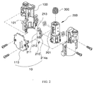
- FIGS. 1 and 2 are views showing a locking-unlocking unit according to one embodiment of the present invention.
- a locking-unlocking unit 10 includes an actuation unit 210 and an actuation guide unit 110.
- the actuation unit 210 is mounted in a lifting body 200 lifted and falling (moved up and down), and the actuation guide unit 110 is fixedly mounted in a fixing body 100.
- the lifting body 200 may be mounted in the fixing body 100 and lifted as described above, and the actuation unit 210 in the lifting body 200 and the actuation guide unit 110 in the fixing body 100 may be engaged with each other not to be arbitrarily separated from each other when the actuation unit 210 performs a circulation operation in the actuation guide unit 110.
- the actuation unit 210 is movably mounted in the lifting body 200, and the actuation guide unit 110 is fixedly mounted in the fixing body 100. In this state, stopping, maintaining in the stopping state, and falling resulting from the releasing of the stopping state as pushing is performed again in the maintaining state of the stopping state are controlled.
- the configuration according to the present invention can be easily manufactured (that is, the configuration can be simplified and easily assembled), and allows actions to be exactly repeated. In addition, failure causes can be overcome by the simple configuration.
- FIG. 3 is a view showing the lifting body mounted in the fixing body
- FIG. 4 is a view showing the lifting body lifted as a fitting protrusion formed on one surface of a lifting plate is fitted into a fitting groove of the lifting body in the above mounting state between the lifting body and the fixing body.
- the lifting body 200 is mounted in the fixing body 100, and the fixing body 100 may be assembled in a dividing state into equal parts.
- the fixing body 100 In the assembling state, the fixing body 100 has an opening 101 vertically formed therein and exposing a rotation groove 201 formed in the lifting body 200.
- FIGS. 5 to 12 are views showing a rising procedure of the actuation unit and the actuation guide unit as the lifting body is lifted, a stopping procedure in the rising state, and a falling procedure according to the releasing of the stopping state according to the present invention.
- the actuation unit 210 mounted in the lifting body 200 is lifted at the same time when the lifting body 200 is lifted and movably coupled to the lifting body 200 as described above.
- the actuation unit 210 includes the lifting plate 211 having both surfaces, the rotation shaft 215 protruding from one surface of the lifting plate 211 for fitting, and a stop protrusion 213 formed on an opposite surface of the lifting plate 211.
- the lifting body 200 is formed therein with the rotation groove 201 to be rotatably fitted around the rotation shaft 215 of the lifting plate 211, so that the rotation groove 201 is simply fitted around the rotation shaft 215 and movable left and right in the fitting state.
- the lifting plate 211 constituting the actuation unit 210 and the stop protrusion 213, which is provided at an upper end of an opposite side of the lifting plate 211 to circulate between the lifting line 111 and the falling line 112 of the actuation guide unit 110 to be described below in detail, may protrude to the extent of being securely mounted in a stop groove 113 between the lifting line 111 and the falling line 112 of the actuation guide unit 110.
- a lifting guide protrusion 212 is additionally provided at a lower end of the opposite surface of the lifting plate 211, and the lifting groove 114 is provided in a recess shape or a through-hole shape in the actuation guide unit 110 while extending vertically. Accordingly, the lifting guide protrusion 212 is lifted after being engaged with the lifting groove 114, so that the lifting of the lifting plate 211 is correctly guided immediately upward.
- the stop protrusion 213 is prevented from interfering with the lifting groove 114. Accordingly, when the lifting plate 211 is lifted, and the stop protrusion 213 circulates between the lifting line 111 and the falling line 112 formed in the actuation guide unit 110, the lifting guide protrusion 212 is lifted in the lifting groove 114 to perform a hinge operation, so that the lifting of the lifting plate 211 can be correctly guided.
- the lifting plate 211 As the lifting plate 211 is primarily pushed, the lifting of the lifting body 200 is started. In this case, the stop protrusion 213 is lifted along the lifting line, and mounted in the stop groove 113 after the lifting has been finished, so that the lifting body 200 is stopped in the lifting state. In this state, if the lifting plate 211 is lifted through the repeatedly pushing actions, the stop protrusion 213 deviates from the stop groove 113 to be released from the stopping state, and thus falls along the falling line 112.
- an elastic rod 214 is provided at one side of the lifting plate 211 while being spaced apart from the lifting plate 211.
- the elastic rod 214 is coupled to a lower end of the lifting plate 211, and has a primarily curved shape c, and a shape a curved again at the top thereof, and a shape b of extending downward. Accordingly, the elastic rod 214 has sufficient elasticity.
- the elastic rod 214 is provided at a front end thereof with a front protrusion 214a formed perpendicularly to the elastic rod 214 so that the front protrusion 214a circulates in contact with an elastic rod guide groove 115 of the actuation guide unit 110 to be described.
- the actuation guide unit 110 which guides lifting when the lifting plate 211 and the elastic rod 214 of the actuation unit 210 are lifted, is provided in a plate shape and fixed to the fixing body 100, includes the lifting groove 114 vertically formed therein to vertically lift the lifting guide protrusion 212 of the lifting plate 211, and the elastic rod guide groove 115 provided at one side of the lifting groove 114 to lift the elastic rod 214, which is lifted together with the lifting plate 211 of the actuation unit, while circulating.
- the lifting line 111 is formed to allow the stop protrusion 213 of the lifting plate 211 to be lifted while circulating as the lifting body 200 is lifted
- the stop groove 113 is formed to stop the lifting of the stop protrusion 213, which is lifted, or to maintain the stopping stopping of the stop protrusion 213, and the falling line 112 is formed at one side of the stop groove 113 to allow the lifting body 200, the stopping state of which is released, to fall.
- the inclination line 111 a having a slow inclination is formed at the side of the lifting line 111 on the bottom surface of the stop groove 113, and the stop protrusion 213 is located under the inclination line 111 a.
- the falling line 112 has a vertical line 112a sharply inclined to allow the stop protrusion 213 to rapidly deviate from the stop groove 113 when the stop protrusion 213 deviates from the stop groove 113.
- the stop protrusion 213 is stopped in the stop groove 113 in the state that the elasticity of the elastic rod 214 is maintained, so that the stop protrusion 213 falls only along the falling line 112.
- the repeatedly lifting and falling of the lifting body 200 performed through the repeat of pushing actions of the lifting body 200 may locate an elastic member 300 immediately over the lifting body 200 mounted in the fixing body 100.
- the stop protrusion 213 when the stop protrusion 213 is lifted along the lifting line 111, the stop protrusion 213 is lifted in close contact with an opposite surface of one wing 113a forming the stop groove 113 and securely mounted and stopped in the stop groove 113 as the stop protrusion 213 deviates from the upper end of the opposite surface of the one wing 113a.
- an anti-passing protrusion 16 protrudes downward over the stop groove 113 while being spaced apart from the stop groove 113.
- a front end 116a of the anti-passing protrusion 116 protruding downward is located in front of the stop groove 113. Accordingly, even if the stop protrusion 213 rapidly lifted along the lifting line 111 rapidly deviates from an upper end of one wing 113 a forming the stop groove 113, the stop protrusion 213 is locked to the anti-passing protrusion 116 and dropped down in front of the stop groove 113, so that the stop protrusion 213 is correctly mounted in the sop groove 113.
- the interval between the front end 116 of the anti-passing protrusion 116 and the front end of one side wing 113a forming the lifting line 111 with a predetermined length and forming the stop groove 113 is smaller than the thickness of the stop protrusion 213 formed on the lifting plate 211. Accordingly, the stop protrusion 213 enters the stop groove 113 through a lateral portion without deviating from the stop groove 113.
- the stop protrusion may be prevented from deviating from the stop groove 113.
- the stop protrusion 213 When the stop protrusion 213 is stopped in the stop groove 113, the elasticity is maintained by the elastic rod 214. Accordingly, if the lifting plate 211 is lifted according to the lifting of the lifting body 200 in the state that the stop protrusion 213 is securely mounted in the stop groove 113, the stop protrusion 213 is lifted from the stop groove 113 while entering the falling line 112 instead of the lifting line 111 as described above.
- the opposite wing 113b which is another wing of the stop groove 113 forming the falling line 112, is formed at a right angle more substantially than an angle that the wing 113a of the lifting line 111 is spread, thereby preventing the stop protrusion from arbitrarily deviating from the stop groove 113 while rapidly entering the falling line.
- the opposite wing 113b forming the stop groove 113 is formed with the height higher than that of the front end of the wing 113a of the lifting line 111 to prevent the stop protrusion from immediately entering the falling line 112.
- the allowable height of the opposite wing 113b must be in the range of pressing the elastic member 300.
- stop protrusion 213 is located in a stand-by groove 177 provided over the lifting groove 114 to be prevented from being fluctuated.
- the front end protrusion 214a formed on the front end of the elastic rod 214 is inclined as the lifting plate 211 is moved along the inclination line 111a, which is slowly inclined. Accordingly, the curved elastic rod 214 is pressed, and the stop protrusion is securely mounted in the stop groove 113 in this state.
- the stop protrusion 213 is lifted to enter the falling line 112 instead of the lifting line 111 by the elastic rod 214, so that the stop protrusion 213 become out of the 113b of the stop groove 113.
- the stop protrusion 213 exactly performs repeated actions while circulating between the lifting line 111 and the falling line 112 according to the lifting and the falling of the lifting body 200.
Landscapes
- Chemical & Material Sciences (AREA)
- Chemical Kinetics & Catalysis (AREA)
- Engineering & Computer Science (AREA)
- General Engineering & Computer Science (AREA)
- Mechanical Engineering (AREA)
- Load-Engaging Elements For Cranes (AREA)
- External Artificial Organs (AREA)
- Lock And Its Accessories (AREA)
Applications Claiming Priority (1)
| Application Number | Priority Date | Filing Date | Title |
|---|---|---|---|
| KR1020150036195A KR101570188B1 (ko) | 2015-03-16 | 2015-03-16 | 반복적인 밀어줌에 의하여 승하강되는 승강체를 상승된 상태에서의 정지와 정지 상태의 해제를 위한 락킹-언락킹구조체 |
Publications (2)
| Publication Number | Publication Date |
|---|---|
| EP3069770A1 true EP3069770A1 (de) | 2016-09-21 |
| EP3069770B1 EP3069770B1 (de) | 2017-11-01 |
Family
ID=54843482
Family Applications (1)
| Application Number | Title | Priority Date | Filing Date |
|---|---|---|---|
| EP16000636.7A Active EP3069770B1 (de) | 2015-03-16 | 2016-03-16 | Verriegelungs-entriegelungsstruktur zum anhalten eines auftriebskörpers, der durch wiederholung von schubvorgängen angehoben und abgesenkt wird, im auftriebszustand und zum auslösen des haltezustands des auftriebskörpers |
Country Status (4)
| Country | Link |
|---|---|
| US (1) | US9863575B2 (de) |
| EP (1) | EP3069770B1 (de) |
| KR (1) | KR101570188B1 (de) |
| CN (1) | CN105999819A (de) |
Families Citing this family (5)
| Publication number | Priority date | Publication date | Assignee | Title |
|---|---|---|---|---|
| KR101572918B1 (ko) * | 2015-03-16 | 2015-12-01 | 주식회사 마이크로필터 | 필터 어셈블리 |
| KR101570188B1 (ko) | 2015-03-16 | 2015-11-19 | 주식회사 마이크로필터 | 반복적인 밀어줌에 의하여 승하강되는 승강체를 상승된 상태에서의 정지와 정지 상태의 해제를 위한 락킹-언락킹구조체 |
| KR101570193B1 (ko) * | 2015-03-16 | 2015-11-18 | 주식회사 마이크로필터 | 반복밀어줌에 의하여 승강되는 승강체의 정방향의 상승을 유도하는 락킹-언락킹구조체 |
| CN115531945B (zh) * | 2022-09-27 | 2024-07-05 | 江苏钲清环保科技有限公司 | 一种过滤装置及纯水设备 |
| CN119755190B (zh) * | 2024-07-16 | 2025-11-04 | 比亚迪股份有限公司 | 一种锁止结构、可旋转桌板以及车辆 |
Citations (3)
| Publication number | Priority date | Publication date | Assignee | Title |
|---|---|---|---|---|
| WO2005115924A2 (en) * | 2004-05-25 | 2005-12-08 | Koslow Technologies Corporation | Twist and lock filter housing |
| WO2008007823A1 (en) * | 2006-07-10 | 2008-01-17 | Joung, Whi-Dong | Water purification filter assembly |
| WO2009025413A1 (en) * | 2007-08-21 | 2009-02-26 | Joung, Whi-Dong | Water purifier filter having a filter washing function |
Family Cites Families (9)
| Publication number | Priority date | Publication date | Assignee | Title |
|---|---|---|---|---|
| US4569281A (en) * | 1985-01-02 | 1986-02-11 | Woods David R | Apparatus for unscrewing jar lids and crushing aluminum cans |
| EP2298431B1 (de) * | 2005-07-20 | 2014-01-01 | 3M Innovative Properties Co. | Fluidfiltrationssystem |
| KR200441175Y1 (ko) * | 2006-11-09 | 2008-07-28 | (주)아모레퍼시픽 | 화장품 용기 뚜껑 체결구조 |
| DE102008002727B4 (de) * | 2008-06-27 | 2020-12-17 | Brita Gmbh | Vorrichtung zur Behandlung von Wasser, insbesondere Filtervorrichtung, und Kartusche |
| US9233322B1 (en) * | 2008-08-08 | 2016-01-12 | Kx Technologies Llc | Push filter with floating key lock |
| CN102149439B (zh) * | 2008-09-16 | 2014-03-12 | 3M创新有限公司 | 滤筒和利用线性致动的系统 |
| KR101590849B1 (ko) * | 2015-03-16 | 2016-02-02 | (주)마이크로필터 | 필터카트리지의 조립체 |
| KR101570188B1 (ko) * | 2015-03-16 | 2015-11-19 | 주식회사 마이크로필터 | 반복적인 밀어줌에 의하여 승하강되는 승강체를 상승된 상태에서의 정지와 정지 상태의 해제를 위한 락킹-언락킹구조체 |
| KR101570193B1 (ko) * | 2015-03-16 | 2015-11-18 | 주식회사 마이크로필터 | 반복밀어줌에 의하여 승강되는 승강체의 정방향의 상승을 유도하는 락킹-언락킹구조체 |
-
2015
- 2015-03-16 KR KR1020150036195A patent/KR101570188B1/ko active Active
-
2016
- 2016-03-16 CN CN201610149589.0A patent/CN105999819A/zh active Pending
- 2016-03-16 US US15/072,083 patent/US9863575B2/en active Active
- 2016-03-16 EP EP16000636.7A patent/EP3069770B1/de active Active
Patent Citations (3)
| Publication number | Priority date | Publication date | Assignee | Title |
|---|---|---|---|---|
| WO2005115924A2 (en) * | 2004-05-25 | 2005-12-08 | Koslow Technologies Corporation | Twist and lock filter housing |
| WO2008007823A1 (en) * | 2006-07-10 | 2008-01-17 | Joung, Whi-Dong | Water purification filter assembly |
| WO2009025413A1 (en) * | 2007-08-21 | 2009-02-26 | Joung, Whi-Dong | Water purifier filter having a filter washing function |
Also Published As
| Publication number | Publication date |
|---|---|
| EP3069770B1 (de) | 2017-11-01 |
| CN105999819A (zh) | 2016-10-12 |
| KR101570188B1 (ko) | 2015-11-19 |
| US20160271538A1 (en) | 2016-09-22 |
| US9863575B2 (en) | 2018-01-09 |
Similar Documents
| Publication | Publication Date | Title |
|---|---|---|
| EP3069770B1 (de) | Verriegelungs-entriegelungsstruktur zum anhalten eines auftriebskörpers, der durch wiederholung von schubvorgängen angehoben und abgesenkt wird, im auftriebszustand und zum auslösen des haltezustands des auftriebskörpers | |
| US9885445B2 (en) | Locking-unlocking structure for guiding forward lifting of lifting body by repeating pushing action | |
| EP3176351B1 (de) | Führungsschienenanordnung und verriegelungsvorrichtung dafür | |
| EP3144457B1 (de) | Trägersystem mit einer gleitschienenanordnung mit verriegelungsvorrichtung | |
| US9808083B2 (en) | Device for releasably connecting a furniture drawer to a guidance unit that moveably guides the drawer in a furniture body | |
| TW201635954A (zh) | 將一前端面板以可卸除方式固定在一抽屜上之固定裝置 | |
| EP3082386B1 (de) | Montagevorrichtung | |
| JP2012055689A (ja) | スライドレール装置 | |
| CN106460439B (zh) | 用于可移动的窗玻璃的带动件、窗玻璃组件 | |
| US9388620B2 (en) | Door stopper and rod locking mechanism | |
| EP2893838A1 (de) | Verstellbare Klammeranordnung und Schiebeanordnung damit | |
| KR102430852B1 (ko) | 도어 스톱용 바닥측 부재 및 도어 스톱 | |
| CN211201471U (zh) | 机械锁及机器人 | |
| KR101659229B1 (ko) | 서랍 안전 잠금장치 및 이를 구비한 서랍장 | |
| CN106820684B (zh) | 抽屉滑轨组件 | |
| CN104470275A (zh) | 一种用于电力控制室的防潮电气抽屉柜 | |
| CN110164045B (zh) | 自动补充杯盖装置和自动售卖机 | |
| CN210039466U (zh) | 拼接装置及显示屏 | |
| CN211422160U (zh) | 锁芯及锁具 | |
| JP6084944B2 (ja) | 扉用の固定構造、およびこれを含む扉装置 | |
| JP2014039707A (ja) | 安全装置つきキャビネット | |
| CN204402201U (zh) | 双向抽屉柜锁扣装置 | |
| ES2764949T3 (es) | Dispositivo para guiar el movimiento de un elemento de empuje y equipo doméstico | |
| JP6656684B1 (ja) | キャビネットの地震ロック装置 | |
| EP3101209A1 (de) | Aushebesicherung für eine äussere schiebetür |
Legal Events
| Date | Code | Title | Description |
|---|---|---|---|
| PUAI | Public reference made under article 153(3) epc to a published international application that has entered the european phase |
Free format text: ORIGINAL CODE: 0009012 |
|
| 17P | Request for examination filed |
Effective date: 20160322 |
|
| AK | Designated contracting states |
Kind code of ref document: A1 Designated state(s): AL AT BE BG CH CY CZ DE DK EE ES FI FR GB GR HR HU IE IS IT LI LT LU LV MC MK MT NL NO PL PT RO RS SE SI SK SM TR |
|
| AX | Request for extension of the european patent |
Extension state: BA ME |
|
| GRAP | Despatch of communication of intention to grant a patent |
Free format text: ORIGINAL CODE: EPIDOSNIGR1 |
|
| RIC1 | Information provided on ipc code assigned before grant |
Ipc: C02F 1/00 20060101ALI20170421BHEP Ipc: B01D 27/08 20060101AFI20170421BHEP |
|
| INTG | Intention to grant announced |
Effective date: 20170523 |
|
| GRAS | Grant fee paid |
Free format text: ORIGINAL CODE: EPIDOSNIGR3 |
|
| GRAA | (expected) grant |
Free format text: ORIGINAL CODE: 0009210 |
|
| AK | Designated contracting states |
Kind code of ref document: B1 Designated state(s): AL AT BE BG CH CY CZ DE DK EE ES FI FR GB GR HR HU IE IS IT LI LT LU LV MC MK MT NL NO PL PT RO RS SE SI SK SM TR |
|
| REG | Reference to a national code |
Ref country code: GB Ref legal event code: FG4D |
|
| REG | Reference to a national code |
Ref country code: CH Ref legal event code: EP Ref country code: AT Ref legal event code: REF Ref document number: 941492 Country of ref document: AT Kind code of ref document: T Effective date: 20171115 |
|
| REG | Reference to a national code |
Ref country code: IE Ref legal event code: FG4D |
|
| REG | Reference to a national code |
Ref country code: DE Ref legal event code: R096 Ref document number: 602016000647 Country of ref document: DE |
|
| REG | Reference to a national code |
Ref country code: NL Ref legal event code: MP Effective date: 20171101 |
|
| REG | Reference to a national code |
Ref country code: LT Ref legal event code: MG4D |
|
| REG | Reference to a national code |
Ref country code: AT Ref legal event code: MK05 Ref document number: 941492 Country of ref document: AT Kind code of ref document: T Effective date: 20171101 |
|
| REG | Reference to a national code |
Ref country code: FR Ref legal event code: PLFP Year of fee payment: 3 |
|
| PG25 | Lapsed in a contracting state [announced via postgrant information from national office to epo] |
Ref country code: LT Free format text: LAPSE BECAUSE OF FAILURE TO SUBMIT A TRANSLATION OF THE DESCRIPTION OR TO PAY THE FEE WITHIN THE PRESCRIBED TIME-LIMIT Effective date: 20171101 Ref country code: SE Free format text: LAPSE BECAUSE OF FAILURE TO SUBMIT A TRANSLATION OF THE DESCRIPTION OR TO PAY THE FEE WITHIN THE PRESCRIBED TIME-LIMIT Effective date: 20171101 Ref country code: NO Free format text: LAPSE BECAUSE OF FAILURE TO SUBMIT A TRANSLATION OF THE DESCRIPTION OR TO PAY THE FEE WITHIN THE PRESCRIBED TIME-LIMIT Effective date: 20180201 Ref country code: FI Free format text: LAPSE BECAUSE OF FAILURE TO SUBMIT A TRANSLATION OF THE DESCRIPTION OR TO PAY THE FEE WITHIN THE PRESCRIBED TIME-LIMIT Effective date: 20171101 Ref country code: ES Free format text: LAPSE BECAUSE OF FAILURE TO SUBMIT A TRANSLATION OF THE DESCRIPTION OR TO PAY THE FEE WITHIN THE PRESCRIBED TIME-LIMIT Effective date: 20171101 Ref country code: NL Free format text: LAPSE BECAUSE OF FAILURE TO SUBMIT A TRANSLATION OF THE DESCRIPTION OR TO PAY THE FEE WITHIN THE PRESCRIBED TIME-LIMIT Effective date: 20171101 |
|
| PG25 | Lapsed in a contracting state [announced via postgrant information from national office to epo] |
Ref country code: GR Free format text: LAPSE BECAUSE OF FAILURE TO SUBMIT A TRANSLATION OF THE DESCRIPTION OR TO PAY THE FEE WITHIN THE PRESCRIBED TIME-LIMIT Effective date: 20180202 Ref country code: RS Free format text: LAPSE BECAUSE OF FAILURE TO SUBMIT A TRANSLATION OF THE DESCRIPTION OR TO PAY THE FEE WITHIN THE PRESCRIBED TIME-LIMIT Effective date: 20171101 Ref country code: AT Free format text: LAPSE BECAUSE OF FAILURE TO SUBMIT A TRANSLATION OF THE DESCRIPTION OR TO PAY THE FEE WITHIN THE PRESCRIBED TIME-LIMIT Effective date: 20171101 Ref country code: HR Free format text: LAPSE BECAUSE OF FAILURE TO SUBMIT A TRANSLATION OF THE DESCRIPTION OR TO PAY THE FEE WITHIN THE PRESCRIBED TIME-LIMIT Effective date: 20171101 Ref country code: IS Free format text: LAPSE BECAUSE OF FAILURE TO SUBMIT A TRANSLATION OF THE DESCRIPTION OR TO PAY THE FEE WITHIN THE PRESCRIBED TIME-LIMIT Effective date: 20180301 Ref country code: BG Free format text: LAPSE BECAUSE OF FAILURE TO SUBMIT A TRANSLATION OF THE DESCRIPTION OR TO PAY THE FEE WITHIN THE PRESCRIBED TIME-LIMIT Effective date: 20180201 Ref country code: LV Free format text: LAPSE BECAUSE OF FAILURE TO SUBMIT A TRANSLATION OF THE DESCRIPTION OR TO PAY THE FEE WITHIN THE PRESCRIBED TIME-LIMIT Effective date: 20171101 |
|
| PG25 | Lapsed in a contracting state [announced via postgrant information from national office to epo] |
Ref country code: CZ Free format text: LAPSE BECAUSE OF FAILURE TO SUBMIT A TRANSLATION OF THE DESCRIPTION OR TO PAY THE FEE WITHIN THE PRESCRIBED TIME-LIMIT Effective date: 20171101 Ref country code: SK Free format text: LAPSE BECAUSE OF FAILURE TO SUBMIT A TRANSLATION OF THE DESCRIPTION OR TO PAY THE FEE WITHIN THE PRESCRIBED TIME-LIMIT Effective date: 20171101 Ref country code: CY Free format text: LAPSE BECAUSE OF FAILURE TO SUBMIT A TRANSLATION OF THE DESCRIPTION OR TO PAY THE FEE WITHIN THE PRESCRIBED TIME-LIMIT Effective date: 20171101 Ref country code: EE Free format text: LAPSE BECAUSE OF FAILURE TO SUBMIT A TRANSLATION OF THE DESCRIPTION OR TO PAY THE FEE WITHIN THE PRESCRIBED TIME-LIMIT Effective date: 20171101 Ref country code: DK Free format text: LAPSE BECAUSE OF FAILURE TO SUBMIT A TRANSLATION OF THE DESCRIPTION OR TO PAY THE FEE WITHIN THE PRESCRIBED TIME-LIMIT Effective date: 20171101 |
|
| REG | Reference to a national code |
Ref country code: DE Ref legal event code: R097 Ref document number: 602016000647 Country of ref document: DE |
|
| PG25 | Lapsed in a contracting state [announced via postgrant information from national office to epo] |
Ref country code: RO Free format text: LAPSE BECAUSE OF FAILURE TO SUBMIT A TRANSLATION OF THE DESCRIPTION OR TO PAY THE FEE WITHIN THE PRESCRIBED TIME-LIMIT Effective date: 20171101 Ref country code: PL Free format text: LAPSE BECAUSE OF FAILURE TO SUBMIT A TRANSLATION OF THE DESCRIPTION OR TO PAY THE FEE WITHIN THE PRESCRIBED TIME-LIMIT Effective date: 20171101 Ref country code: SM Free format text: LAPSE BECAUSE OF FAILURE TO SUBMIT A TRANSLATION OF THE DESCRIPTION OR TO PAY THE FEE WITHIN THE PRESCRIBED TIME-LIMIT Effective date: 20171101 Ref country code: IT Free format text: LAPSE BECAUSE OF FAILURE TO SUBMIT A TRANSLATION OF THE DESCRIPTION OR TO PAY THE FEE WITHIN THE PRESCRIBED TIME-LIMIT Effective date: 20171101 |
|
| PLBE | No opposition filed within time limit |
Free format text: ORIGINAL CODE: 0009261 |
|
| STAA | Information on the status of an ep patent application or granted ep patent |
Free format text: STATUS: NO OPPOSITION FILED WITHIN TIME LIMIT |
|
| 26N | No opposition filed |
Effective date: 20180802 |
|
| PG25 | Lapsed in a contracting state [announced via postgrant information from national office to epo] |
Ref country code: SI Free format text: LAPSE BECAUSE OF FAILURE TO SUBMIT A TRANSLATION OF THE DESCRIPTION OR TO PAY THE FEE WITHIN THE PRESCRIBED TIME-LIMIT Effective date: 20171101 Ref country code: MC Free format text: LAPSE BECAUSE OF FAILURE TO SUBMIT A TRANSLATION OF THE DESCRIPTION OR TO PAY THE FEE WITHIN THE PRESCRIBED TIME-LIMIT Effective date: 20171101 |
|
| REG | Reference to a national code |
Ref country code: BE Ref legal event code: MM Effective date: 20180331 |
|
| REG | Reference to a national code |
Ref country code: IE Ref legal event code: MM4A |
|
| PG25 | Lapsed in a contracting state [announced via postgrant information from national office to epo] |
Ref country code: LU Free format text: LAPSE BECAUSE OF NON-PAYMENT OF DUE FEES Effective date: 20180316 |
|
| PG25 | Lapsed in a contracting state [announced via postgrant information from national office to epo] |
Ref country code: IE Free format text: LAPSE BECAUSE OF NON-PAYMENT OF DUE FEES Effective date: 20180316 |
|
| PG25 | Lapsed in a contracting state [announced via postgrant information from national office to epo] |
Ref country code: BE Free format text: LAPSE BECAUSE OF NON-PAYMENT OF DUE FEES Effective date: 20180331 |
|
| REG | Reference to a national code |
Ref country code: CH Ref legal event code: PL |
|
| PG25 | Lapsed in a contracting state [announced via postgrant information from national office to epo] |
Ref country code: CH Free format text: LAPSE BECAUSE OF NON-PAYMENT OF DUE FEES Effective date: 20190331 Ref country code: MT Free format text: LAPSE BECAUSE OF NON-PAYMENT OF DUE FEES Effective date: 20180316 Ref country code: LI Free format text: LAPSE BECAUSE OF NON-PAYMENT OF DUE FEES Effective date: 20190331 |
|
| PG25 | Lapsed in a contracting state [announced via postgrant information from national office to epo] |
Ref country code: TR Free format text: LAPSE BECAUSE OF FAILURE TO SUBMIT A TRANSLATION OF THE DESCRIPTION OR TO PAY THE FEE WITHIN THE PRESCRIBED TIME-LIMIT Effective date: 20171101 |
|
| PG25 | Lapsed in a contracting state [announced via postgrant information from national office to epo] |
Ref country code: PT Free format text: LAPSE BECAUSE OF FAILURE TO SUBMIT A TRANSLATION OF THE DESCRIPTION OR TO PAY THE FEE WITHIN THE PRESCRIBED TIME-LIMIT Effective date: 20171101 |
|
| PG25 | Lapsed in a contracting state [announced via postgrant information from national office to epo] |
Ref country code: HU Free format text: LAPSE BECAUSE OF FAILURE TO SUBMIT A TRANSLATION OF THE DESCRIPTION OR TO PAY THE FEE WITHIN THE PRESCRIBED TIME-LIMIT; INVALID AB INITIO Effective date: 20160316 Ref country code: MK Free format text: LAPSE BECAUSE OF NON-PAYMENT OF DUE FEES Effective date: 20171101 |
|
| PG25 | Lapsed in a contracting state [announced via postgrant information from national office to epo] |
Ref country code: AL Free format text: LAPSE BECAUSE OF FAILURE TO SUBMIT A TRANSLATION OF THE DESCRIPTION OR TO PAY THE FEE WITHIN THE PRESCRIBED TIME-LIMIT Effective date: 20171101 |
|
| REG | Reference to a national code |
Ref country code: FR Ref legal event code: PLFP Year of fee payment: 8 |
|
| REG | Reference to a national code |
Ref country code: DE Ref legal event code: R082 Ref document number: 602016000647 Country of ref document: DE Representative=s name: PUSCHMANN BORCHERT KAISER KLETTNER PATENTANWAE, DE Ref country code: DE Ref legal event code: R082 Ref document number: 602016000647 Country of ref document: DE Representative=s name: ADVOTEC. PATENT- UND RECHTSANWALTSPARTNERSCHAF, DE |
|
| PGFP | Annual fee paid to national office [announced via postgrant information from national office to epo] |
Ref country code: DE Payment date: 20250528 Year of fee payment: 10 |
|
| REG | Reference to a national code |
Ref country code: DE Ref legal event code: R082 Ref document number: 602016000647 Country of ref document: DE Representative=s name: ADVOTEC. PATENT- UND RECHTSANWALTSPARTNERSCHAF, DE |
|
| PGFP | Annual fee paid to national office [announced via postgrant information from national office to epo] |
Ref country code: GB Payment date: 20260324 Year of fee payment: 11 |
|
| PGFP | Annual fee paid to national office [announced via postgrant information from national office to epo] |
Ref country code: FR Payment date: 20260324 Year of fee payment: 11 |