EP3069865A1 - Mehrschichtige Kraftfahrzeugrohrleitung - Google Patents
Mehrschichtige Kraftfahrzeugrohrleitung Download PDFInfo
- Publication number
- EP3069865A1 EP3069865A1 EP15159473.6A EP15159473A EP3069865A1 EP 3069865 A1 EP3069865 A1 EP 3069865A1 EP 15159473 A EP15159473 A EP 15159473A EP 3069865 A1 EP3069865 A1 EP 3069865A1
- Authority
- EP
- European Patent Office
- Prior art keywords
- layer
- profiled
- maxima
- motor vehicle
- pipeline
- Prior art date
- Legal status (The legal status is an assumption and is not a legal conclusion. Google has not performed a legal analysis and makes no representation as to the accuracy of the status listed.)
- Granted
Links
- 229920003023 plastic Polymers 0.000 claims abstract description 7
- 239000004033 plastic Substances 0.000 claims abstract description 7
- 239000010410 layer Substances 0.000 claims description 188
- 239000002318 adhesion promoter Substances 0.000 claims description 32
- 230000004888 barrier function Effects 0.000 claims description 28
- 239000000446 fuel Substances 0.000 claims description 5
- 239000002344 surface layer Substances 0.000 claims 1
- 229920000219 Ethylene vinyl alcohol Polymers 0.000 description 8
- 239000004952 Polyamide Substances 0.000 description 6
- 239000002131 composite material Substances 0.000 description 6
- 229920002647 polyamide Polymers 0.000 description 6
- 239000012790 adhesive layer Substances 0.000 description 5
- 239000012815 thermoplastic material Substances 0.000 description 5
- 230000000295 complement effect Effects 0.000 description 4
- 230000032798 delamination Effects 0.000 description 4
- 239000004715 ethylene vinyl alcohol Substances 0.000 description 4
- 238000001125 extrusion Methods 0.000 description 4
- 238000009792 diffusion process Methods 0.000 description 3
- 230000007774 longterm Effects 0.000 description 2
- 239000000126 substance Substances 0.000 description 2
- 230000015572 biosynthetic process Effects 0.000 description 1
- 239000007767 bonding agent Substances 0.000 description 1
- 230000015556 catabolic process Effects 0.000 description 1
- 239000012530 fluid Substances 0.000 description 1
- 230000001788 irregular Effects 0.000 description 1
- 230000002035 prolonged effect Effects 0.000 description 1
Images


Classifications
-
- F—MECHANICAL ENGINEERING; LIGHTING; HEATING; WEAPONS; BLASTING
- F02—COMBUSTION ENGINES; HOT-GAS OR COMBUSTION-PRODUCT ENGINE PLANTS
- F02M—SUPPLYING COMBUSTION ENGINES IN GENERAL WITH COMBUSTIBLE MIXTURES OR CONSTITUENTS THEREOF
- F02M37/00—Apparatus or systems for feeding liquid fuel from storage containers to carburettors or fuel-injection apparatus; Arrangements for purifying liquid fuel specially adapted for, or arranged on, internal-combustion engines
- F02M37/0011—Constructional details; Manufacturing or assembly of elements of fuel systems; Materials therefor
- F02M37/0017—Constructional details; Manufacturing or assembly of elements of fuel systems; Materials therefor related to fuel pipes or their connections, e.g. joints or sealings
-
- F—MECHANICAL ENGINEERING; LIGHTING; HEATING; WEAPONS; BLASTING
- F16—ENGINEERING ELEMENTS AND UNITS; GENERAL MEASURES FOR PRODUCING AND MAINTAINING EFFECTIVE FUNCTIONING OF MACHINES OR INSTALLATIONS; THERMAL INSULATION IN GENERAL
- F16L—PIPES; JOINTS OR FITTINGS FOR PIPES; SUPPORTS FOR PIPES, CABLES OR PROTECTIVE TUBING; MEANS FOR THERMAL INSULATION IN GENERAL
- F16L9/00—Rigid pipes
- F16L9/12—Rigid pipes of plastics with or without reinforcement
-
- B—PERFORMING OPERATIONS; TRANSPORTING
- B29—WORKING OF PLASTICS; WORKING OF SUBSTANCES IN A PLASTIC STATE IN GENERAL
- B29C—SHAPING OR JOINING OF PLASTICS; SHAPING OF MATERIAL IN A PLASTIC STATE, NOT OTHERWISE PROVIDED FOR; AFTER-TREATMENT OF THE SHAPED PRODUCTS, e.g. REPAIRING
- B29C48/00—Extrusion moulding, i.e. expressing the moulding material through a die or nozzle which imparts the desired form; Apparatus therefor
- B29C48/03—Extrusion moulding, i.e. expressing the moulding material through a die or nozzle which imparts the desired form; Apparatus therefor characterised by the shape of the extruded material at extrusion
- B29C48/09—Articles with cross-sections having partially or fully enclosed cavities, e.g. pipes or channels
-
- B—PERFORMING OPERATIONS; TRANSPORTING
- B29—WORKING OF PLASTICS; WORKING OF SUBSTANCES IN A PLASTIC STATE IN GENERAL
- B29C—SHAPING OR JOINING OF PLASTICS; SHAPING OF MATERIAL IN A PLASTIC STATE, NOT OTHERWISE PROVIDED FOR; AFTER-TREATMENT OF THE SHAPED PRODUCTS, e.g. REPAIRING
- B29C48/00—Extrusion moulding, i.e. expressing the moulding material through a die or nozzle which imparts the desired form; Apparatus therefor
- B29C48/16—Articles comprising two or more components, e.g. co-extruded layers
- B29C48/18—Articles comprising two or more components, e.g. co-extruded layers the components being layers
- B29C48/21—Articles comprising two or more components, e.g. co-extruded layers the components being layers the layers being joined at their surfaces
-
- B—PERFORMING OPERATIONS; TRANSPORTING
- B32—LAYERED PRODUCTS
- B32B—LAYERED PRODUCTS, i.e. PRODUCTS BUILT-UP OF STRATA OF FLAT OR NON-FLAT, e.g. CELLULAR OR HONEYCOMB, FORM
- B32B1/00—Layered products having a non-planar shape
- B32B1/08—Tubular products
-
- B—PERFORMING OPERATIONS; TRANSPORTING
- B32—LAYERED PRODUCTS
- B32B—LAYERED PRODUCTS, i.e. PRODUCTS BUILT-UP OF STRATA OF FLAT OR NON-FLAT, e.g. CELLULAR OR HONEYCOMB, FORM
- B32B27/00—Layered products comprising a layer of synthetic resin
- B32B27/06—Layered products comprising a layer of synthetic resin as the main or only constituent of a layer, which is next to another layer of the same or of a different material
-
- B—PERFORMING OPERATIONS; TRANSPORTING
- B32—LAYERED PRODUCTS
- B32B—LAYERED PRODUCTS, i.e. PRODUCTS BUILT-UP OF STRATA OF FLAT OR NON-FLAT, e.g. CELLULAR OR HONEYCOMB, FORM
- B32B27/00—Layered products comprising a layer of synthetic resin
- B32B27/06—Layered products comprising a layer of synthetic resin as the main or only constituent of a layer, which is next to another layer of the same or of a different material
- B32B27/08—Layered products comprising a layer of synthetic resin as the main or only constituent of a layer, which is next to another layer of the same or of a different material of synthetic resin
-
- B—PERFORMING OPERATIONS; TRANSPORTING
- B32—LAYERED PRODUCTS
- B32B—LAYERED PRODUCTS, i.e. PRODUCTS BUILT-UP OF STRATA OF FLAT OR NON-FLAT, e.g. CELLULAR OR HONEYCOMB, FORM
- B32B27/00—Layered products comprising a layer of synthetic resin
- B32B27/30—Layered products comprising a layer of synthetic resin comprising vinyl (co)polymers; comprising acrylic (co)polymers
- B32B27/306—Layered products comprising a layer of synthetic resin comprising vinyl (co)polymers; comprising acrylic (co)polymers comprising vinyl acetate or vinyl alcohol (co)polymers
-
- B—PERFORMING OPERATIONS; TRANSPORTING
- B32—LAYERED PRODUCTS
- B32B—LAYERED PRODUCTS, i.e. PRODUCTS BUILT-UP OF STRATA OF FLAT OR NON-FLAT, e.g. CELLULAR OR HONEYCOMB, FORM
- B32B27/00—Layered products comprising a layer of synthetic resin
- B32B27/34—Layered products comprising a layer of synthetic resin comprising polyamides
-
- B—PERFORMING OPERATIONS; TRANSPORTING
- B32—LAYERED PRODUCTS
- B32B—LAYERED PRODUCTS, i.e. PRODUCTS BUILT-UP OF STRATA OF FLAT OR NON-FLAT, e.g. CELLULAR OR HONEYCOMB, FORM
- B32B3/00—Layered products comprising a layer with external or internal discontinuities or unevennesses, or a layer of non-planar shape; Layered products comprising a layer having particular features of form
- B32B3/02—Layered products comprising a layer with external or internal discontinuities or unevennesses, or a layer of non-planar shape; Layered products comprising a layer having particular features of form characterised by features of form at particular places, e.g. in edge regions
-
- B—PERFORMING OPERATIONS; TRANSPORTING
- B32—LAYERED PRODUCTS
- B32B—LAYERED PRODUCTS, i.e. PRODUCTS BUILT-UP OF STRATA OF FLAT OR NON-FLAT, e.g. CELLULAR OR HONEYCOMB, FORM
- B32B3/00—Layered products comprising a layer with external or internal discontinuities or unevennesses, or a layer of non-planar shape; Layered products comprising a layer having particular features of form
- B32B3/26—Layered products comprising a layer with external or internal discontinuities or unevennesses, or a layer of non-planar shape; Layered products comprising a layer having particular features of form characterised by a particular shape of the outline of the cross-section of a continuous layer; characterised by a layer with cavities or internal voids ; characterised by an apertured layer
-
- B—PERFORMING OPERATIONS; TRANSPORTING
- B32—LAYERED PRODUCTS
- B32B—LAYERED PRODUCTS, i.e. PRODUCTS BUILT-UP OF STRATA OF FLAT OR NON-FLAT, e.g. CELLULAR OR HONEYCOMB, FORM
- B32B3/00—Layered products comprising a layer with external or internal discontinuities or unevennesses, or a layer of non-planar shape; Layered products comprising a layer having particular features of form
- B32B3/26—Layered products comprising a layer with external or internal discontinuities or unevennesses, or a layer of non-planar shape; Layered products comprising a layer having particular features of form characterised by a particular shape of the outline of the cross-section of a continuous layer; characterised by a layer with cavities or internal voids ; characterised by an apertured layer
- B32B3/263—Layered products comprising a layer with external or internal discontinuities or unevennesses, or a layer of non-planar shape; Layered products comprising a layer having particular features of form characterised by a particular shape of the outline of the cross-section of a continuous layer; characterised by a layer with cavities or internal voids ; characterised by an apertured layer characterised by a layer having non-uniform thickness
-
- B—PERFORMING OPERATIONS; TRANSPORTING
- B32—LAYERED PRODUCTS
- B32B—LAYERED PRODUCTS, i.e. PRODUCTS BUILT-UP OF STRATA OF FLAT OR NON-FLAT, e.g. CELLULAR OR HONEYCOMB, FORM
- B32B3/00—Layered products comprising a layer with external or internal discontinuities or unevennesses, or a layer of non-planar shape; Layered products comprising a layer having particular features of form
- B32B3/26—Layered products comprising a layer with external or internal discontinuities or unevennesses, or a layer of non-planar shape; Layered products comprising a layer having particular features of form characterised by a particular shape of the outline of the cross-section of a continuous layer; characterised by a layer with cavities or internal voids ; characterised by an apertured layer
- B32B3/28—Layered products comprising a layer with external or internal discontinuities or unevennesses, or a layer of non-planar shape; Layered products comprising a layer having particular features of form characterised by a particular shape of the outline of the cross-section of a continuous layer; characterised by a layer with cavities or internal voids ; characterised by an apertured layer characterised by a layer comprising a deformed thin sheet, i.e. the layer having its entire thickness deformed out of the plane, e.g. corrugated, crumpled
-
- B—PERFORMING OPERATIONS; TRANSPORTING
- B32—LAYERED PRODUCTS
- B32B—LAYERED PRODUCTS, i.e. PRODUCTS BUILT-UP OF STRATA OF FLAT OR NON-FLAT, e.g. CELLULAR OR HONEYCOMB, FORM
- B32B3/00—Layered products comprising a layer with external or internal discontinuities or unevennesses, or a layer of non-planar shape; Layered products comprising a layer having particular features of form
- B32B3/26—Layered products comprising a layer with external or internal discontinuities or unevennesses, or a layer of non-planar shape; Layered products comprising a layer having particular features of form characterised by a particular shape of the outline of the cross-section of a continuous layer; characterised by a layer with cavities or internal voids ; characterised by an apertured layer
- B32B3/30—Layered products comprising a layer with external or internal discontinuities or unevennesses, or a layer of non-planar shape; Layered products comprising a layer having particular features of form characterised by a particular shape of the outline of the cross-section of a continuous layer; characterised by a layer with cavities or internal voids ; characterised by an apertured layer characterised by a layer formed with recesses or projections, e.g. hollows, grooves, protuberances, ribs
-
- B—PERFORMING OPERATIONS; TRANSPORTING
- B32—LAYERED PRODUCTS
- B32B—LAYERED PRODUCTS, i.e. PRODUCTS BUILT-UP OF STRATA OF FLAT OR NON-FLAT, e.g. CELLULAR OR HONEYCOMB, FORM
- B32B7/00—Layered products characterised by the relation between layers; Layered products characterised by the relative orientation of features between layers, or by the relative values of a measurable parameter between layers, i.e. products comprising layers having different physical, chemical or physicochemical properties; Layered products characterised by the interconnection of layers
- B32B7/04—Interconnection of layers
-
- B—PERFORMING OPERATIONS; TRANSPORTING
- B32—LAYERED PRODUCTS
- B32B—LAYERED PRODUCTS, i.e. PRODUCTS BUILT-UP OF STRATA OF FLAT OR NON-FLAT, e.g. CELLULAR OR HONEYCOMB, FORM
- B32B7/00—Layered products characterised by the relation between layers; Layered products characterised by the relative orientation of features between layers, or by the relative values of a measurable parameter between layers, i.e. products comprising layers having different physical, chemical or physicochemical properties; Layered products characterised by the interconnection of layers
- B32B7/04—Interconnection of layers
- B32B7/10—Interconnection of layers at least one layer having inter-reactive properties
-
- B—PERFORMING OPERATIONS; TRANSPORTING
- B32—LAYERED PRODUCTS
- B32B—LAYERED PRODUCTS, i.e. PRODUCTS BUILT-UP OF STRATA OF FLAT OR NON-FLAT, e.g. CELLULAR OR HONEYCOMB, FORM
- B32B7/00—Layered products characterised by the relation between layers; Layered products characterised by the relative orientation of features between layers, or by the relative values of a measurable parameter between layers, i.e. products comprising layers having different physical, chemical or physicochemical properties; Layered products characterised by the interconnection of layers
- B32B7/04—Interconnection of layers
- B32B7/12—Interconnection of layers using interposed adhesives or interposed materials with bonding properties
-
- F—MECHANICAL ENGINEERING; LIGHTING; HEATING; WEAPONS; BLASTING
- F16—ENGINEERING ELEMENTS AND UNITS; GENERAL MEASURES FOR PRODUCING AND MAINTAINING EFFECTIVE FUNCTIONING OF MACHINES OR INSTALLATIONS; THERMAL INSULATION IN GENERAL
- F16L—PIPES; JOINTS OR FITTINGS FOR PIPES; SUPPORTS FOR PIPES, CABLES OR PROTECTIVE TUBING; MEANS FOR THERMAL INSULATION IN GENERAL
- F16L9/00—Rigid pipes
- F16L9/12—Rigid pipes of plastics with or without reinforcement
- F16L9/121—Rigid pipes of plastics with or without reinforcement with three layers
-
- F—MECHANICAL ENGINEERING; LIGHTING; HEATING; WEAPONS; BLASTING
- F16—ENGINEERING ELEMENTS AND UNITS; GENERAL MEASURES FOR PRODUCING AND MAINTAINING EFFECTIVE FUNCTIONING OF MACHINES OR INSTALLATIONS; THERMAL INSULATION IN GENERAL
- F16L—PIPES; JOINTS OR FITTINGS FOR PIPES; SUPPORTS FOR PIPES, CABLES OR PROTECTIVE TUBING; MEANS FOR THERMAL INSULATION IN GENERAL
- F16L9/00—Rigid pipes
- F16L9/12—Rigid pipes of plastics with or without reinforcement
- F16L9/123—Rigid pipes of plastics with or without reinforcement with four layers
-
- F—MECHANICAL ENGINEERING; LIGHTING; HEATING; WEAPONS; BLASTING
- F16—ENGINEERING ELEMENTS AND UNITS; GENERAL MEASURES FOR PRODUCING AND MAINTAINING EFFECTIVE FUNCTIONING OF MACHINES OR INSTALLATIONS; THERMAL INSULATION IN GENERAL
- F16L—PIPES; JOINTS OR FITTINGS FOR PIPES; SUPPORTS FOR PIPES, CABLES OR PROTECTIVE TUBING; MEANS FOR THERMAL INSULATION IN GENERAL
- F16L9/00—Rigid pipes
- F16L9/12—Rigid pipes of plastics with or without reinforcement
- F16L9/133—Rigid pipes of plastics with or without reinforcement the walls consisting of two layers
-
- B—PERFORMING OPERATIONS; TRANSPORTING
- B29—WORKING OF PLASTICS; WORKING OF SUBSTANCES IN A PLASTIC STATE IN GENERAL
- B29C—SHAPING OR JOINING OF PLASTICS; SHAPING OF MATERIAL IN A PLASTIC STATE, NOT OTHERWISE PROVIDED FOR; AFTER-TREATMENT OF THE SHAPED PRODUCTS, e.g. REPAIRING
- B29C48/00—Extrusion moulding, i.e. expressing the moulding material through a die or nozzle which imparts the desired form; Apparatus therefor
- B29C48/25—Component parts, details or accessories; Auxiliary operations
- B29C48/30—Extrusion nozzles or dies
- B29C48/32—Extrusion nozzles or dies with annular openings, e.g. for forming tubular articles
- B29C48/335—Multiple annular extrusion nozzles in coaxial arrangement, e.g. for making multi-layered tubular articles
-
- B—PERFORMING OPERATIONS; TRANSPORTING
- B32—LAYERED PRODUCTS
- B32B—LAYERED PRODUCTS, i.e. PRODUCTS BUILT-UP OF STRATA OF FLAT OR NON-FLAT, e.g. CELLULAR OR HONEYCOMB, FORM
- B32B2307/00—Properties of the layers or laminate
- B32B2307/70—Other properties
- B32B2307/724—Permeability to gases, adsorption
-
- B—PERFORMING OPERATIONS; TRANSPORTING
- B32—LAYERED PRODUCTS
- B32B—LAYERED PRODUCTS, i.e. PRODUCTS BUILT-UP OF STRATA OF FLAT OR NON-FLAT, e.g. CELLULAR OR HONEYCOMB, FORM
- B32B2307/00—Properties of the layers or laminate
- B32B2307/70—Other properties
- B32B2307/724—Permeability to gases, adsorption
- B32B2307/7242—Non-permeable
-
- B—PERFORMING OPERATIONS; TRANSPORTING
- B32—LAYERED PRODUCTS
- B32B—LAYERED PRODUCTS, i.e. PRODUCTS BUILT-UP OF STRATA OF FLAT OR NON-FLAT, e.g. CELLULAR OR HONEYCOMB, FORM
- B32B2307/00—Properties of the layers or laminate
- B32B2307/70—Other properties
- B32B2307/724—Permeability to gases, adsorption
- B32B2307/7242—Non-permeable
- B32B2307/7244—Oxygen barrier
-
- B—PERFORMING OPERATIONS; TRANSPORTING
- B32—LAYERED PRODUCTS
- B32B—LAYERED PRODUCTS, i.e. PRODUCTS BUILT-UP OF STRATA OF FLAT OR NON-FLAT, e.g. CELLULAR OR HONEYCOMB, FORM
- B32B2307/00—Properties of the layers or laminate
- B32B2307/70—Other properties
- B32B2307/726—Permeability to liquids, absorption
- B32B2307/7265—Non-permeable
-
- B—PERFORMING OPERATIONS; TRANSPORTING
- B32—LAYERED PRODUCTS
- B32B—LAYERED PRODUCTS, i.e. PRODUCTS BUILT-UP OF STRATA OF FLAT OR NON-FLAT, e.g. CELLULAR OR HONEYCOMB, FORM
- B32B2597/00—Tubular articles, e.g. hoses, pipes
-
- B—PERFORMING OPERATIONS; TRANSPORTING
- B32—LAYERED PRODUCTS
- B32B—LAYERED PRODUCTS, i.e. PRODUCTS BUILT-UP OF STRATA OF FLAT OR NON-FLAT, e.g. CELLULAR OR HONEYCOMB, FORM
- B32B2605/00—Vehicles
-
- B—PERFORMING OPERATIONS; TRANSPORTING
- B32—LAYERED PRODUCTS
- B32B—LAYERED PRODUCTS, i.e. PRODUCTS BUILT-UP OF STRATA OF FLAT OR NON-FLAT, e.g. CELLULAR OR HONEYCOMB, FORM
- B32B2605/00—Vehicles
- B32B2605/08—Cars
-
- F—MECHANICAL ENGINEERING; LIGHTING; HEATING; WEAPONS; BLASTING
- F16—ENGINEERING ELEMENTS AND UNITS; GENERAL MEASURES FOR PRODUCING AND MAINTAINING EFFECTIVE FUNCTIONING OF MACHINES OR INSTALLATIONS; THERMAL INSULATION IN GENERAL
- F16L—PIPES; JOINTS OR FITTINGS FOR PIPES; SUPPORTS FOR PIPES, CABLES OR PROTECTIVE TUBING; MEANS FOR THERMAL INSULATION IN GENERAL
- F16L11/00—Hoses, i.e. flexible pipes
- F16L11/04—Hoses, i.e. flexible pipes made of rubber or flexible plastics
- F16L2011/047—Hoses, i.e. flexible pipes made of rubber or flexible plastics with a diffusion barrier layer
Definitions
- the invention relates to a multilayer motor vehicle pipeline, in particular a multilayer fuel pipeline for motor vehicles, wherein the pipeline has at least two layers of plastic, preferably at least three layers of plastic.
- the layers consist in particular of thermoplastic material.
- Multilayer automotive pipelines or fuel pipelines of the aforementioned type are known from practice in different embodiments.
- One problem is often the adhesion between the individual layers in the layered laminate.
- Many known multi-layer pipelines of this kind show after prolonged operation undesirable delamination properties, which can ultimately make the motor vehicle pipelines unusable. It can lead to leaks and vehicle breakdown.
- the delamination is usually reinforced or accelerated by external chemical, thermal and mechanical influences.
- These delamination problems basically apply more or less to all layers in a layer laminate of the pipeline.
- adhesion promoter layers or the layers connected by them are frequently affected in the laminate composite.
- Corresponding problems often arise for barrier layers or permeation and / or diffusion barrier layers present in the layer composite, for example barrier layers of ethylene-vinyl alcohol copolymer (EVOH).
- EVOH ethylene-vinyl alcohol copolymer
- the invention addresses the technical problem of specifying a multi-layer motor vehicle pipeline of the type mentioned, in which the disadvantages described above can be avoided or can be minimized and in which, in particular, a multilayer composite which is stable in the long term against delamination can be achieved.
- the invention teaches a multilayer motor vehicle pipeline, in particular a multilayer fuel pipeline for motor vehicles, wherein the pipeline has at least two layers of plastic, preferably at least three layers of plastic, wherein at least one surface of at least one layer connected to a further layer is profiled, wherein the profiling has maxima and minima and wherein the height difference ⁇ h between the maxima and the maxima adjacent or immediately adjacent minima between 1 and 100 microns, preferably between 1 and 50 microns, preferably between 1 and 25 microns and more preferably between 1 and 20 microns.
- the at least two layers, preferably at least three layers of the pipeline consist of thermoplastic material or essentially consist of thermoplastic material.
- the at least one profiled layer according to the invention is profiled according to the invention on its two opposite surfaces, wherein preferably each profiling of the two surfaces has the maxima and minima specified above.
- the at least one profiled layer according to the invention or the at least one profiled surface of this layer circulate over at least 80%, preferably over at least 90% and preferably over at least 95% of the circumference of the pipeline.
- the maxima and minima of the profiling are arranged uniformly or substantially evenly distributed over the circumference of the pipeline.
- the surface of a further or a second layer connected to a profiled surface of a first layer is likewise profiled in accordance with the invention, wherein this profiling of the further layer or the second layer is preferably analogous or complementary to that of FIG Profiling the first layer is formed.
- the second layer expediently likewise has maxima and minima, and the height difference ⁇ h between the maxima and the minima immediately adjacent minima is between 1 and 100 ⁇ m, preferably between 1 and 50 ⁇ m, preferably between 1 and 25 ⁇ m, and particularly preferably between 1 and 20 ⁇ m.
- At least one layer or at least one first layer is profiled according to the invention on its two surfaces and connected to at least one and preferably to each of these according to the invention profiled surfaces is a profiled according to the invention surface of another layer.
- the profilings of a surface of the one or the first layer profiled in accordance with the invention are complementary to the profilings of a surface of a further or second layer profiled according to the invention.
- the maxima of the surface of a first layer profiled according to the invention interlock positively - and preferably non-positively - in the minima of the surface profiled according to the invention of a further layer or second layer connected thereto and expediently the maxima of the surface profiled in accordance with the invention
- the further or second layer has a form-fitting - and preferably non-positive fit - engagement in the minima of the surface of the first layer profiled in accordance with the invention.
- the height difference ⁇ h between the maxima and the immediately adjacent minima in the first layer and in the other or in the second layer is the same or substantially the same.
- the maxima and minima of the first layer and the maxima and minima of the further or second layer connected thereto have the same shape or essentially the same shape.
- a particularly recommended embodiment of the invention is characterized in that the distances a between the maxima and the minima immediately adjacent minima of a surface profiled according to the invention 1 to 100 .mu.m, preferably 1 to 50 .mu.m, preferably 1 to 25 .mu.m and particularly preferably 2 to 20 ⁇ m. It is within the scope of the invention that the distances a are measured in the circumferential direction of the pipeline.
- the at least one layer provided with at least one profiled surface according to the invention is a middle layer of the pipeline, which is connected via its two surfaces to a respective further layer of the pipeline.
- both surfaces of the middle layer are formed as surfaces profiled according to the invention.
- a surface of a further layer connected to a surface of the middle layer which is profiled in accordance with the invention is designed as a profiled surface and in particular as a surface profiled in accordance with the invention.
- the middle layer according to a particularly preferred embodiment of the invention is an adhesion promoter layer between two Layers of pipeline laminate. However, it may also be a barrier layer or a permeation and / or diffusion barrier layer.
- a proven embodiment of the invention is characterized in that it is an adhesive layer according to the invention is a bonding agent layer, which is connected with its two surfaces to a further layer, preferably both surfaces of the adhesive layer profiled and recommended according to the invention profiled profiled.
- a primer layer expediently has a thickness of 0.02 mm to 0.15 mm, preferably a thickness of 0.03 mm to 0.12 mm and particularly preferably a thickness of 0.03 mm to 0.10 mm.
- a particularly preferred embodiment of the invention is characterized in that at least one surface of the adhesion promoter layer profiled in accordance with the invention is connected to a barrier layer or a permeation and / or diffusion barrier layer.
- the surface of the barrier layer connected to the adhesion promoter layer is also profiled according to the invention.
- a preferred embodiment of the invention is characterized in that two adhesion promoter layers are provided in the multilayer pipeline, both of which are profiled according to the invention and preferably both are profiled on their two opposite surfaces and are particularly preferably profiled according to the invention.
- a layer or only one layer is interposed between the two adhesion promoter layers, wherein this intermediate layer is preferably a barrier layer.
- at least the two surfaces of the adhesion promoter layers connected to the barrier layer are profiled in accordance with the invention. Empfohlenewag the barrier layer is then profiled according to the invention at its two opposite surfaces.
- Both primer layers have the thicknesses given above for the primer layer.
- further layers of the multilayer pipeline are connected to the surfaces facing away from the barrier layer or surfaces of the two adhesion promoter layers profiled according to the invention.
- at least one of the layers of polyamide or essentially of polyamide connected directly outside to the adhesion promoter layers preferably consist of polyamide or essentially of polyamide.
- a primer layer ensures or ensures the adhesion between the two layers connected to their surfaces.
- the adhesion promoter layer or the adhesion promoter layers may be, for example, an adhesion promoter layer or adhesion promoter layers based on polyamide.
- the barrier layer consists of ethylene-vinyl alcohol copolymer (EVOH) or essentially of ethylene-vinyl alcohol copolymer (EVOH).
- the thickness of the barrier layer is expediently 0.05 to 0.3 mm, preferably 0.10 to 0.25 mm and particularly preferably 0.11 to 0.20 mm, for example 0.15 mm. If according to a preferred embodiment of the invention in the layer composite at least one, preferably at least two profiled according to the invention profiled on their surfaces or profiled according to the invention on both surfaces adhesion promoter layers are provided, it is within the scope of the invention that the respectively profiled surfaces according to the invention in each case connected layers or . whose connected surfaces are profiled according to the invention.
- Profiles according to the invention means, in particular, that the above-specified height difference ⁇ h and preferably the above-specified distances a are provided. It is further within the scope of the invention that the above-mentioned layer thicknesses of the layers in the presence according to the invention profiled surfaces are measured only from the minima of the layers.
- a further embodiment variant of the invention is characterized in that a layer provided with a profiled surface according to the invention is the inner layer of the pipeline, which is connected with its outer surface profiled according to the invention to a further layer. It is within the scope of the invention that this inner layer with its inner surface comes into contact with the fluid medium flowing through the pipeline. Conveniently, the inner surface of the inner layer of the pipe is unprofiled or formed substantially unprofiled. Moreover, according to a preferred embodiment of the invention, the outer surface of the outer layer of the pipeline is unprofiled or substantially unprofiled.
- the multi-layer motor vehicle pipeline or fuel pipe according to the invention is produced by coextrusion. It is therefore within the scope of the invention that the layers or all layers of the multilayer pipeline consist of plastic or of thermoplastic material.
- the layers or all layers of the multilayer pipeline consist of plastic or of thermoplastic material.
- at least the layer provided with at least one profiled surface according to the invention and the at least one layer connected to the profiled surface according to the invention are produced by coextrusion. It is within the scope of the invention that the extruder used for coextrusion is formed with the proviso that during coextrusion, the at least one layer with the at least one profiled surface formed according to the invention is formed.
- the extruder used for the extrusion of the pipeline according to the invention comprises annular channels for the extrusion of the individual layers of the pipeline.
- at least one annular channel is expediently provided with transverse webs extending in the radial direction.
- the transverse webs can extend over the entire radial width of the annular channel.
- the transverse webs may extend only over a part of the radial width of the respective annular channel.
- the interruption generated by the transverse webs causes the formation of the maxima and minima of the profiled surface or surfaces produced according to the invention.
- the relevant layer of the pipe is profiled on both opposite surfaces according to the invention / is.
- the maxima and minima of a surface profiled in accordance with the invention extend in the longitudinal direction of the pipeline. It is therefore recommended that the maxima and minima are formed in the form of running in the longitudinal direction of the pipe webs and grooves. It is preferred - but not essential - that the height difference .DELTA.h between the maxima and minima in the longitudinal direction of the pipeline remains constant or remains substantially constant. The same applies to the distances a between the maxima and the minima.
- the at least one profiled layer according to the invention or the profiled surface of this layer and preferably at least two and particularly preferably all layers profiled according to the invention or the profiled surfaces of these layers profiled according to the invention have at least 80%, preferably extend over at least 90% and more preferably over at least 95% of the circumference of the pipeline.
- the at least one profiled layer according to the invention or the profiled surface according to the invention runs this layer and according to particularly proven embodiment, at least two layers profiled according to the invention and preferably at least all inventively profiled layers or their invention profiled surfaces over the entire circumference of the pipeline to.
- a highly recommended embodiment of the invention is characterized in that the profiling of the at least one profiled surface according to the invention has a wave-shaped cross-section.
- the peaks coincide with the maxima and the troughs with the minima of the profiling according to the invention.
- the wave crests and / or the wave troughs of this profile, which is wave-shaped in cross-section, can be pointed and / or rounded.
- the maxima and the minima or the wave crests and the wave troughs extend in the form of webs and grooves in the longitudinal direction of the pipeline. According to a recommended embodiment of the invention, these webs and grooves are arranged parallel to the longitudinal axis L of the pipeline or substantially parallel to the longitudinal axis L of the pipeline. It is furthermore within the scope of the invention that the webs of a surface profiled in accordance with the invention engage in the grooves of a surface profiled according to the invention connected thereto, preferably engage in a form-locking and preferably frictionally engaged manner and vice versa.
- the invention is based on the finding that due to the profiling according to the invention of at least one surface of a layer of the pipeline according to the invention a very effective and functionally reliable adhesion between the corresponding adjacent layers of the pipeline can be achieved. This is especially true for the preferred embodiment of the invention where both interconnected surfaces of two Profiles of adjacent layers are formed profiled and wherein the profiling of a layer is complementary to the profiling of the other layer. It is also essential that this advantage of the invention can be achieved with very simple and inexpensive means.
- the profiles according to the invention can be produced without problems in an extrusion or co-extrusion with a suitably designed extruder.
- Particularly medium layers in the laminate composite of a motor vehicle pipeline according to the invention can be held particularly firmly adhering in the composite and are characterized in the long term by chemical influences and in thermal and mechanical stresses by excellent adhesion or adhesion.
- the profiling according to the invention has proven particularly successful in the case of adhesive layers.
- These primer layers then ensure a particularly effective and strong bond of the layers connected thereto. Consequently, it is possible to dispense with further efforts to improve the adhesion, and to that extent a pipeline according to the invention is characterized by low expenditure and low costs.
- the pipeline 1 has a total of six layers 2 to 7.
- a middle barrier layer 5 is provided, on whose surfaces 5.1 and 5.2 in each case an adhesion promoter layer 4 or 6 is connected.
- the inner adhesion promoter layer 4 is adjoined by two inner layers 3 and 2 and the outer adhesion promoter layer 6 is adjoined by an outer layer 7.
- the Fig. 1 shows a known from the prior art six-layer automotive pipeline.
- the surfaces of the layers, in particular the surfaces 4.1 and 4.2 of the inner adhesion promoter layer 4 and the surfaces 6.1 and 6.2 of the outer adhesion promoter layer 6 and also the two surfaces 5.1 and 5.2 of the middle barrier layer 5 are formed here smooth or unprofiled.
- the Fig. 2 and 3 show a pipeline according to the invention.
- the outside surface 4.2 of the inner adhesion promoter layer 4 and the inside surface 6.1 of the outer adhesion promoter layer 6 are profiled according to the invention.
- the profiling has maxima 9 and minima 10, wherein the height difference .DELTA.h between the maxima 9 to the maxima 9 immediately adjacent minima 10 between 1 and 20 microns, preferably between 5 and 15 microns.
- the height difference .DELTA.h may be about 10 microns.
- the height difference ⁇ h between the maxima 9 and the minima 10 is expediently and in the exemplary embodiment measured as the radial distance of the maxima and minima.
- the inside surface 5.1 of the barrier layer 5 facing the outside surface 4.2 of the inner adhesion promoter layer 4 is also profiled in accordance with the invention.
- the profiling of the surfaces 5.1 and 5.2 of the barrier layer 5 is preferred and in the exemplary embodiment complementary to the profiles of the respectively associated surfaces 4.2 and 6.1 of the adhesive layers 4, 6 are formed.
- the measured in the circumferential direction of the pipe 1 distances a between the maxima 9 and the maxima 9 immediately adjacent minima 10 are preferably 1 to 20 microns and very preferably 5 to 15 microns.
- the profiled surfaces 4.2, 5.1, 5.2 and 6.1 are very preferred and wavy in cross-section in the embodiment. As a rule, a more or less irregular wave structure is achieved.
- the middle barrier layer 5 may consist of ethylene vinyl alcohol copolymer (EVOH) in the exemplary embodiment.
- the adhesion promoter layers 4, 6 connected thereto are expediently adhesion promoter layers 4, 6 based on polyamide.
- the thickness of the middle barrier layer 5 is preferred and in the exemplary embodiment 0.1 to 0.2 mm and for example 0.15 mm.
- the thickness of the adhesion promoter layers is preferred and in the exemplary embodiment 0.02 mm to 0.1 mm, preferably 0.03 mm to 0.07 mm and for example 0.05 mm.
- the layers of the multilayer automotive pipeline according to the invention consist of a preferred embodiment of the invention made of thermoplastic material. It is within the scope of the invention that the multi-layer motor vehicle pipeline according to the invention is produced by coextrusion.
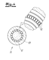
- the Fig. 4 shows the cross section of an extruder 11 for such a coextrusion, with this extruder 11 according to the invention profiled surfaces of a layer can be produced.
- the extruder 11 has an annular channel 12 with radial transverse webs 13. With the aid of these radial transverse webs 13 in the annular channel 12, the respective extruded layer can be provided with according to the invention profiled or wavy surfaces.
- the extruder 11 may have further corresponding annular channels 12 for the layers of the pipeline 1, if further profiled surfaces are to be produced. These ring channels 12 are in the Fig. 4 but not further illustrated. As far as shows Fig. 4 only a greatly simplified cross-section of a corresponding extruder 11.
Landscapes
- Engineering & Computer Science (AREA)
- Mechanical Engineering (AREA)
- General Engineering & Computer Science (AREA)
- Chemical & Material Sciences (AREA)
- Combustion & Propulsion (AREA)
- Laminated Bodies (AREA)
- Rigid Pipes And Flexible Pipes (AREA)
- Health & Medical Sciences (AREA)
- Chemical Kinetics & Catalysis (AREA)
- Medicinal Chemistry (AREA)
- Polymers & Plastics (AREA)
- Organic Chemistry (AREA)
Abstract
Description
- Die Erfindung betrifft eine mehrschichtige Kraftfahrzeugrohrleitung, insbesondere eine mehrschichtige Kraftstoffrohrleitung für Kraftfahrzeuge, wobei die Rohrleitung zumindest zwei Schichten aus Kunststoff, bevorzugt zumindest drei Schichten aus Kunststoff aufweist. Die Schichten bestehen dabei insbesondere aus thermoplastischem Kunststoff.
- Mehrschichtige Kraftfahrzeugrohrleitungen bzw. Kraftstoffrohrleitungen der vorstehend genannten Art sind aus der Praxis in unterschiedlichen Ausführungsformen bekannt. Ein Problem ist oftmals die Haftung zwischen den einzelnen Schichten im Schichtenlaminat. Viele bekannte mehrschichtige Rohrleitungen dieser Art zeigen nach längerer Betriebszeit unerwünschte Delaminationseigenschaften, die letztendlich die Kraftfahrzeugrohrleitungen unbrauchbar machen können. Es kann zu Leckagen und zum Fahrzeugausfall kommen. Die Delamination wird durch äußere chemische, thermische und mechanische Einflüsse in der Regel noch verstärkt bzw. beschleunigt. Diese Delaminationsprobleme treffen grundsätzlich mehr oder weniger für alle Schichten in einem Schichtenlaminat der Rohrleitung zu. Besonders betroffen sind aber häufig im Laminatverbund angeordnete Haftvermittlerschichten bzw. die durch sie verbundenen Schichten. Entsprechende Probleme ergeben sich oftmals auch für im Schichtenverbund vorhandene Barriereschichten bzw. Permeations-und/oder Diffusions-Barriereschichten, beispielsweise Barriereschichten aus Ethylen-Vinylalkohol-Copolymer (EVOH). Die aus der Praxis bekannten mehrschichtigen Kraftfahrzeugrohrleitungen sind insoweit verbesserungsbedürftig.
- Demgegenüber liegt der Erfindung das technische Problem zugrunde, eine mehrschichtige Kraftfahrzeugrohrleitung der eingangs genannten Art anzugeben, bei der die vorstehend beschriebenen Nachteile vermieden werden können bzw. minimiert werden können und bei der insbesondere ein langfristig gegenüber Delamination stabiler Mehrschichtenverbund erzielt werden kann.
- Zur Lösung des technischen Problems lehrt die Erfindung eine mehrschichtige Kraftfahrzeugrohrleitung, insbesondere eine mehrschichtige Kraftstoffrohrleitung für Kraftfahrzeuge, wobei die Rohrleitung zumindest zwei Schichten aus Kunststoff, bevorzugt zumindest drei Schichten aus Kunststoff aufweist,
wobei zumindest eine mit einer weiteren Schicht verbundene Oberfläche zumindest einer Schicht profiliert ausgebildet ist, wobei die Profilierung Maxima und Minima aufweist und wobei die Höhendifferenz Δh zwischen den Maxima und den den Maxima benachbarten bzw. unmittelbar benachbarten Minima zwischen 1 und 100 µm, vorzugsweise zwischen 1 und 50 µm liegt, bevorzugt zwischen 1 und 25 µm und besonders bevorzugt zwischen 1 und 20 µm liegt. - Es liegt im Rahmen der Erfindung, dass die zumindest zwei Schichten, bevorzugt mindestens drei Schichten der Rohrleitung aus thermoplastischem Kunststoff bestehen bzw. im Wesentlichen aus thermoplastischem Kunststoff bestehen. Weiterhin liegt es im Rahmen der Erfindung, dass die zumindest eine erfindungsgemäß profilierte Schicht an ihren beiden gegenüberliegenden Oberflächen erfindungsgemäß profiliert ausgebildet ist, wobei vorzugsweise jede Profilierung der beiden Oberflächen die vorstehend spezifizierten Maxima und Minima aufweist. - Es empfiehlt sich, dass die zumindest eine erfindungsgemäß profilierte Schicht bzw. die zumindest eine erfindungsgemäß profilierte Oberfläche dieser Schicht über zumindest 80 %, vorzugsweise über zumindest 90 % und bevorzugt über zumindest 95 % des Umfanges der Rohrleitung umläuft. Besonders bevorzugt läuft die zumindest eine erfindungsgemäß profilierte Schicht bzw. die zumindest eine erfindungsgemäß profilierte Oberfläche dieser Schicht über den gesamten Umfang der Rohrleitung um. Zweckmäßigerweise sind die Maxima und Minima der Profilierung gleichmäßig bzw. im Wesentlichen gleichmäßig über den Umfang der Rohrleitung verteilt angeordnet.
- Es liegt im Rahmen der Erfindung, dass die mit einer erfindungsgemäß profilierten Oberfläche einer ersten Schicht verbundene Oberfläche einer weiteren bzw. einer zweiten Schicht ebenfalls erfindungsgemäß profiliert ausgebildet ist, wobei vorzugsweise diese Profilierung der weiteren Schicht bzw. der zweiten Schicht analog bzw. komplementär zu der Profilierung der ersten Schicht ausgebildet ist. So weist die zweite Schicht zweckmäßigerweise ebenfalls Maxima und Minima auf und die Höhendifferenz Δh zwischen den Maxima und den den Maxima unmittelbar benachbarten Minima liegt zwischen 1 und 100 µm, vorzugsweise zwischen 1 und 50 µm liegt, bevorzugt zwischen 1 und 25 µm und besonders bevorzugt zwischen 1 und 20 µm. Nach einer empfohlenen Ausführungsform der Erfindung ist zumindest eine Schicht bzw. zumindest eine erste Schicht an ihren beiden Oberflächen erfindungsgemäß profiliert ausgebildet und an zumindest eine und bevorzugt an jede dieser erfindungsgemäß profilierten Oberflächen ist eine erfindungsgemäß profilierte Oberfläche einer weiteren Schicht angeschlossen. Vorzugsweise sind die Profilierungen einer erfindungsgemäß profilierten Oberfläche der einen bzw. der ersten Schicht komplementär zu den Profilierungen einer daran angeschlossenen erfindungsgemäß profilierten Oberfläche einer weiteren bzw. zweiten Schicht ausgebildet.
- Es liegt im Rahmen der Erfindung, dass die Maxima der erfindungsgemäß profilierten Oberfläche einer ersten Schicht formschlüssig - und bevorzugt kraftschlüssig - in die Minima der erfindungsgemäß profilierten Oberfläche einer daran angeschlossenen weiteren Schicht bzw. zweiten Schicht eingreifen und dass zweckmäßigerweise die Maxima der erfindungsgemäß profilierten Oberfläche der weiteren bzw. zweiten Schicht umgekehrt formschlüssig - und empfohlenermaßen kraftschlüssig - in die Minima der erfindungsgemäß profilierten Oberfläche der ersten Schicht eingreifen. Dementsprechend ist die Höhendifferenz Δh zwischen den Maxima und den unmittelbar benachbarten Minima bei der ersten Schicht und bei der weiteren bzw. bei der zweiten Schicht gleich bzw. im Wesentlichen gleich. Es liegt weiterhin im Rahmen der Erfindung, dass die Maxima und Minima der ersten Schicht und die Maxima und Minima der daran angeschlossenen weiteren bzw. zweiten Schicht die gleiche Form bzw. im Wesentlichen die gleiche Form aufweisen.
- Eine besonders empfohlene Ausführungsform der Erfindung ist dadurch gekennzeichnet, dass die Abstände a zwischen den Maxima und den den Maxima unmittelbar benachbarten Minima einer erfindungsgemäß profilierten Oberfläche 1 bis 100 µm, vorzugsweise 1 bis 50 µm, bevorzugt 1 bis 25 µm und besonders bevorzugt 2 bis 20 µm betragen. Es liegt dabei im Rahmen der Erfindung, dass die Abstände a in Umfangsrichtung der Rohrleitung gemessen werden.
- Nach einer empfohlenen Ausführungsvariante der Erfindung ist die zumindest eine mit zumindest einer erfindungsgemäß profilierten Oberfläche versehene Schicht eine mittlere Schicht der Rohrleitung, die über ihre beiden Oberflächen mit jeweils einer weiteren Schicht der Rohrleitung verbunden ist. Gemäß einer bevorzugten Ausführungsform sind dabei beide Oberflächen der mittleren Schicht als erfindungsgemäß profilierte Oberflächen ausgebildet. Zweckmäßigerweise ist eine mit einer erfindungsgemäß profilierten Oberfläche der mittleren Schicht verbundene Oberfläche einer weiteren Schicht als profilierte Oberfläche und insbesondere als erfindungsgemäß profilierte Oberfläche ausgeführt. Bei der mittleren Schicht handelt es sich nach besonders bevorzugter Ausführungsform der Erfindung um eine Haftvermittlerschicht zwischen zwei Schichten des Rohrleitungslaminates. Es kann sich dabei aber auch um eine Barriereschicht bzw. eine Permeations- und/oder Diffusions-Barriereschicht handeln.
- Eine bewährte Ausführungsform der Erfindung ist dadurch gekennzeichnet, dass es sich bei einer erfindungsgemäß profilierten Schicht um eine Haftvermittlerschicht handelt, die mit ihren beiden Oberflächen an jeweils eine weitere Schicht angeschlossen ist, wobei vorzugsweise beide Oberflächen der Haftvermittlerschicht profiliert und empfohlenermaßen erfindungsgemäß profiliert ausgebildet sind. Eine solche Haftvermittlerschicht weist zweckmäßigerweise eine Dicke von 0,02 mm bis 0,15 mm, vorzugsweise eine Dicke von 0,03 mm bis 0,12 mm und besonders bevorzugt eine Dicke von 0,03 mm bis 0,10 mm auf. Eine besonders bevorzugte Ausführungsform der Erfindung zeichnet sich dadurch aus, dass zumindest eine erfindungsgemäß profilierte Oberfläche der Haftvermittlerschicht an eine Barriereschicht bzw. eine Permeations- und/oder Diffusions-Barriereschicht angeschlossen ist. Zweckmäßigerweise ist auch die an die Haftvermittlerschicht angeschlossene Oberfläche der Barriereschicht erfindungsgemäß profiliert. Eine bevorzugte Ausführungsform der Erfindung ist dadurch gekennzeichnet, dass in der mehrschichtigen Rohrleitung zwei Haftvermittlerschichten vorgesehen sind, die beide erfindungsgemäß profiliert sind und vorzugsweise beide an ihren beiden gegenüberliegenden Oberflächen profiliert und besonders bevorzugt erfindungsgemäß profiliert sind. Nach einer empfohlenen Ausführungsform ist zwischen den beiden Haftvermittlerschichten eine Schicht bzw. lediglich eine Schicht zwischengeschaltet, wobei es sich bei dieser zwischengeschalteten Schicht vorzugsweise um eine Barriereschicht handelt. Dabei sind zweckmäßigerweise zumindest die beiden mit der Barriereschicht verbundenen Oberflächen der Haftvermittlerschichten erfindungsgemäß profiliert. Empfohlenermaßen ist auch die Barriereschicht dann an ihren beiden gegenüberliegenden Oberflächen erfindungsgemäß profiliert. Vorzugsweise weisen beide Haftvermittlerschichten die oben für die Haftvermittlerschicht angegebenen Dicken auf. Zweckmäßigerweise sind an den der Barriereschicht abgewandten Oberflächen bzw. erfindungsgemäß profilierten Oberflächen der beiden Haftvermittlerschichten weitere Schichten der mehrschichtigen Rohrleitung angeschlossen. Dabei besteht gemäß einer Ausführungsform zumindest eine der außen unmittelbar an die Haftvermittlerschichten angeschlossenen Schichten aus Polyamid bzw. im Wesentlichen aus Polyamid. Vorzugsweise bestehen beide unmittelbar angeschlossene Schichten aus Polyamid bzw. im Wesentlichen aus Polyamid. Es versteht sich, dass eine Haftvermittlerschicht die Haftung zwischen den beiden an ihren Oberflächen angeschlossenen Schichten gewährleistet bzw. sicherstellt. Bei der Haftvermittlerschicht bzw. bei den Haftvermittlerschichten kann es sich beispielsweise um eine Haftvermittlerschicht bzw. um Haftvermittlerschichten auf Basis von Polyamid handeln. Die Barriereschicht besteht nach einer Ausführungsform der Erfindung aus Ethylen-Vinylalkohol-Copolymer (EVOH) bzw. im Wesentlichen aus Ethylen-Vinylalkohol-Copolymer (EVOH). Die Dicke der Barriereschicht beträgt zweckmäßigerweise 0,05 bis 0,3 mm, bevorzugt 0,10 bis 0,25 mm und besonders bevorzugt 0,11 bis 0,20 mm, beispielsweise 0,15 mm. Wenn nach bevorzugter Ausführungsform der Erfindung im Schichtenverbund zumindest eine, bevorzugt zumindest zwei an ihren Oberflächen erfindungsgemäß profilierte bzw. an ihren beiden Oberflächen erfindungsgemäß profilierte Haftvermittlerschichten vorgesehen sind, liegt es im Rahmen der Erfindung, dass auch die an deren erfindungsgemäß profilierten Oberflächen jeweils angeschlossenen Schichten bzw. deren angeschlossene Oberflächen erfindungsgemäß profiliert sind. Erfindungsgemäß profiliert meint insbesondere, dass die oben spezifizierte Höhendifferenz Δh und bevorzugt die oben spezifizierten Abstände a vorgesehen sind. Es liegt weiterhin im Rahmen der Erfindung, dass die oben angegebenen Schichtdicken der Schichten bei Vorhandensein erfindungsgemäß profilierter Oberflächen lediglich von den Minima der Schichten aus gemessen werden.
- Eine weitere Ausführungsvariante der Erfindung ist dadurch gekennzeichnet, dass eine mit einer erfindungsgemäß profilierten Oberfläche versehene Schicht die innere Schicht der Rohrleitung ist, die mit ihrer äußeren erfindungsgemäß profilierten Oberfläche an eine weitere Schicht angeschlossen ist. Es liegt im Rahmen der Erfindung, dass diese innere Schicht mit ihrer inneren Oberfläche mit dem die Rohrleitung durchströmenden fluiden Medium in Kontakt kommt. Zweckmäßigerweise ist die innere Oberfläche der inneren Schicht der Rohrleitung unprofiliert bzw. im Wesentlichen unprofiliert ausgebildet. - Im Übrigen ist nach bevorzugter Ausführungsform der Erfindung die Außenoberfläche der äußeren Schicht der Rohrleitung unprofiliert bzw. im Wesentlichen unprofiliert ausgebildet.
- Nach besonders empfohlener Ausführungsform der Erfindung wird die erfindungsgemäße mehrschichtige Kraftfahrzeugrohrleitung bzw. Kraftstoffrohrleitung durch Koextrusion hergestellt. Es liegt somit im Rahmen der Erfindung, dass die Schichten bzw. alle Schichten der mehrschichtigen Rohrleitung aus Kunststoff bzw. aus thermoplastischem Kunststoff bestehen. - Zweckmäßigerweise wird zumindest die mit zumindest einer erfindungsgemäß profilierten Oberfläche versehene Schicht und die zumindest eine an die erfindungsgemäß profilierte Oberfläche angeschlossene Schicht durch Koextrusion hergestellt. Es liegt im Rahmen der Erfindung, das der für die Koextrusion eingesetzte Extruder mit der Maßgabe ausgebildet ist, dass bei der Koextrusion die zumindest eine Schicht mit der zumindest einen erfindungsgemäß profiliert ausgebildeten Oberfläche entsteht. Es liegt weiterhin im Rahmen der Erfindung, dass der für die Extrusion der erfindungsgemäßen Rohrleitung eingesetzte Extruder Ringkanäle für die Extrusion der einzelnen Schichten der Rohrleitung aufweist. Zur Realisierung der zumindest einen erfindungsgemäß profilierten Oberfläche zumindest einer Schicht ist zweckmäßigerweise zumindest ein Ringkanal mit in radialer Richtung verlaufenden Querstegen versehen. Dabei können sich die Querstege über die gesamte radiale Weite des Ringkanals erstrecken. Insbesondere wenn eine Schicht mit nur einer erfindungsgemäß profilierten Oberfläche hergestellt werden soll, können sich die Querstege aber auch nur über einen Teil der radialen Weite des betreffenden Ringkanals erstrecken. Die durch die Querstege erzeugte Unterbrechung erwirkt die Bildung der Maxima und Minima der erfindungsgemäß hergestellten profilierten Oberfläche bzw. Oberflächen. Es liegt dabei im Rahmen der Erfindung, dass die betreffende Schicht der Rohrleitung an beiden gegenüberliegenden Oberflächen erfindungsgemäß profiliert ausgebildet ist/wird.
- Zweckmäßigerweise erstrecken sich die Maxima und Minima einer erfindungsgemäß profilierten Oberfläche in Längsrichtung der Rohrleitung. Es empfiehlt sich somit, dass die Maxima und Minima in Form von in Längsrichtung der Rohrleitung verlaufenden Stegen und Nuten ausgebildet sind. Dabei ist es bevorzugt - aber nicht unbedingt erforderlich - dass die Höhendifferenz Δh zwischen den Maxima und Minima in Längsrichtung der Rohrleitung konstant bleibt bzw. im Wesentlichen konstant bleibt. Entsprechendes gilt auch für die Abstände a zwischen den Maxima und den Minima. - Es liegt im Rahmen der Erfindung, dass sich die zumindest eine erfindungsgemäß profilierte Schicht bzw. die erfindungsgemäß profilierte Oberfläche dieser Schicht und dass sich bevorzugt zumindest zwei und besonders bevorzugt alle erfindungsgemäß profilierten Schichten bzw. die erfindungsgemäß profilierten Oberflächen dieser Schichten über zumindest 80 %, vorzugsweise über zumindest 90 % und besonders bevorzugt über zumindest 95 % des Umfanges der Rohrleitung erstrecken. Nach sehr empfohlener Ausführungsform läuft die zumindest eine erfindungsgemäß profilierte Schicht bzw. die erfindungsgemäß profilierte Oberfläche dieser Schicht und gemäß besonders bewährter Ausführungsvariante zumindest zwei erfindungsgemäß profilierte Schichten und bevorzugt zumindest alle erfindungsgemäß profilierten Schichten bzw. deren erfindungsgemäß profilierte Oberflächen über den gesamten Umfang der Rohrleitung um.
- Eine sehr empfohlene Ausführungsform der Erfindung ist dadurch gekennzeichnet, dass die Profilierung der zumindest einen erfindungsgemäß profilierten Oberfläche im Querschnitt wellenförmig ausgebildet ist. Bei dieser Ausführungsform entsprechen die Wellenberge den Maxima und die Wellentäler den Minima der erfindungsgemäßen Profilierung. Die Wellenberge und/oder die Wellentäler dieser im Querschnitt wellenförmigen Profilierung können dabei spitz und/oder abgerundet ausgebildet sein.
- Es liegt im Rahmen der Erfindung, dass sich die Maxima und die Minima bzw. die Wellenberge und die Wellentäler in Form von Stegen und Nuten in Längsrichtung der Rohrleitung erstrecken. Nach einer empfohlenen Ausführungsform der Erfindung sind diese Stege und Nuten parallel zur Längsachse L der Rohrleitung bzw. im Wesentlichen parallel zur Längsachse L der Rohrleitung angeordnet. Es liegt fernerhin im Rahmen der Erfindung, dass die Stege einer erfindungsgemäß profilierten Oberfläche in die Nuten einer daran angeschlossenen erfindungsgemäß profilierten Oberfläche eingreifen, vorzugsweise formschlüssig und bevorzugt kraftschlüssig eingreifen und umgekehrt.
- Der Erfindung liegt die Erkenntnis zugrunde, dass aufgrund der erfindungsgemäßen Profilierung zumindest einer Oberfläche einer Schicht der erfindungsgemäßen Rohrleitung eine sehr effektive und funktionssichere Haftung zwischen den entsprechenden benachbarten Schichten der Rohrleitung erzielt werden kann. Das trifft insbesondere für die bevorzugte Ausführungsform der Erfindung zu, bei der beide miteinander verbundene Oberflächen zweier benachbarter Schichten profiliert ausgebildet sind und wobei die Profilierung der einen Schicht komplementär zu der Profilierung der anderen Schicht ist. Wesentlich ist auch, dass dieser erfindungsgemäße Vorteil mit sehr einfachen und wenig aufwendigen Mitteln erzielt werden kann. Die erfindungsgemäßen Profilierungen können ohne Probleme bei einer Extrusion bzw. Koextrusion mit einem entsprechend ausgestalteten Extruder hergestellt werden. Besonders mittlere Schichten im Laminatverbund einer erfindungsgemäßen Kraftfahrzeugrohrleitung können besonders fest haftend in dem Verbund gehalten werden und zeichnen sich auch langfristig bei chemischen Einflüssen sowie bei thermischen und mechanischen Beanspruchungen durch eine exzellente Haftung bzw. Adhäsion aus. Besonders bewährt hat sich die erfindungsgemäße Profilierung bei Haftvermittlerschichten. Diese Haftvermittlerschichten stellen dann einen besonders effektiven und festen Verbund der daran angeschlossenen Schichten sicher. Demzufolge kann auf weiteren Aufwand zur Verbesserung der Haftung verzichtet werden und insoweit zeichnet sich eine erfindungsgemäße Rohrleitung durch geringen Aufwand und geringe Kosten aus.
- Nachfolgend wird die Erfindung anhand einer lediglich einer Ausführungsbeispiel darstellenden Zeichnung näher erläutert. Es zeigen in schematischer Darstellung:
- Fig. 1
- einen Querschnitt durch eine mehrschichtige bzw. sechsschichtige Rohrleitung nach dem Stand der Technik,
- Fig. 2
- eine mit erfindungsgemäßen Profilierungen ausgestattete mehrschichtige bzw. sechsschichtige Rohrleitung,
- Fig. 3
- den Gegenstand gemäß
Fig. 2 in perspektivischer Ansicht, - Fig. 4
- eine sehr schematische Darstellung des Querschnittes eines Extruders zur Herstellung einer erfindungsgemäßen Rohrleitung.
- Im Ausführungsbeispiel nach den Figuren weist die Rohrleitung 1 insgesamt sechs Schichten 2 bis 7 auf. Es ist eine mittlere Barriereschicht 5 vorgesehen, an deren Oberflächen 5.1 und 5.2 jeweils eine Haftvermittlerschicht 4 bzw. 6 angeschlossen ist. An die innere Haftvermittlerschicht 4 schließen zwei innere Schichten 3 und 2 an und an die äußere Haftvermittlerschicht 6 schließt eine äußere Schicht 7 an. Die
Fig. 1 zeigt eine aus dem Stand der Technik bekannte sechsschichtige Kraftfahrzeugrohrleitung. Die Oberflächen der Schichten, insbesondere die Oberflächen 4.1 und 4.2 der inneren Haftvermittlerschicht 4 sowie die Oberflächen 6.1 und 6.2 der äußeren Haftvermittlerschicht 6 und auch die beiden Oberflächen 5.1 und 5.2 der mittleren Barriereschicht 5 sind hier glatt bzw. unprofiliert ausgebildet. - Die
Fig. 2 und3 zeigen dagegen eine erfindungsgemäße Rohrleitung. Hier ist die außenseitige Oberfläche 4.2 der inneren Haftvermittlerschicht 4 sowie die innenseitige Oberfläche 6.1 der äußeren Haftvermittlerschicht 6 erfindungsgemäß profiliert ausgebildet. Die Profilierung weist Maxima 9 und Minima 10 auf, wobei der Höhenunterschied Δh zwischen den Maxima 9 den den Maxima 9 unmittelbar benachbarten Minima 10 zwischen 1 und 20 µm, bevorzugt zwischen 5 und 15 µm liegt. Im Ausführungsbeispiel mag die Höhendifferenz Δh etwa 10 µm betragen. Die Höhendifferenz Δh zwischen den Maxima 9 und den Minima 10 wird zweckmäßigerweise und im Ausführungsbeispiel als der radiale Abstand der Maxima und Minima gemessen. Das ist in dem vergrößerten Ausschnitt derFig. 2 dargestellt. Vorzugsweise und im Ausführungsbeispiel ist auch die der außenseitigen Oberfläche 4.2 der inneren Haftvermittlerschicht 4 zugewandte innenseitige Oberfläche 5.1 der Barriereschicht 5 erfindungsgemäß profiliert ausgebildet. Ebenso ist auch die der innseitigen Oberfläche 6.1 der äußeren Haftvermittlerschicht 6 zugewandte außenseitige Oberfläche 5.2 der Barriereschicht 5 erfindungsgemäß profiliert ausgebildet. Die Profilierung der Oberflächen 5.1 und 5.2 der Barriereschicht 5 ist bevorzugt und im Ausführungsbeispiel komplementär zu den Profilierungen der jeweils zugeordneten Oberflächen 4.2 und 6.1 der Haftvermittlerschichten 4, 6 ausgebildet. Empfohlenermaßen greifen die Maxima 9 der außenseitigen Oberfläche 4.2 der inneren Haftvermittlerschicht 4 in die Minima 10 der innenseitigen Oberfläche 5.1 der Barriereschicht 5 formschlüssig und bevorzugt auch kraftschlüssig ein und umgekehrt. Zweckmäßigerweise greifen die Maxima 9 der innenseitigen Oberfläche 6.1 der äußeren Haftvermittlerschicht 6 formschlüssig und bevorzugt auch kraftschlüssig in die Minima 10 der außenseitigen Oberfläche 5.2 der Barriereschicht 5 ein und umgekehrt. Es findet somit gleichsam eine Verkrallung der Haftvermittlerschichten 4, 6 mit der Barriereschicht 5 über die ineinandergreifenden Profilierungen bzw. Maxima 9 und Minima 10 statt. Die in Umfangsrichtung der Rohrleitung 1 gemessenen Abstände a zwischen den Maxima 9 und den den Maxima 9 unmittelbar benachbarten Minima 10 betragen vorzugsweise 1 bis 20 µm und sehr bevorzugt 5 bis 15 µm. Insbesondere in derFig. 2 ist erkennbar, dass die profilierten Oberflächen 4.2, 5.1, 5.2 und 6.1 sehr bevorzugt und im Ausführungsbeispiel im Querschnitt wellenförmig ausgebildet sind. Dabei wird in der Regel eine mehr oder weniger unregelmäßige Wellenstruktur erzielt. - Die mittlere Barriereschicht 5 mag im Ausführungsbeispiel aus EthylenVinylalkohol-Copolymer (EVOH) bestehen. Die daran angeschlossenen Haftvermittlerschichten 4, 6 sind zweckmäßigerweise Haftvermittlerschichten 4, 6 auf Basis von Polyamid. Die Dicke der mittleren Barriereschicht 5 beträgt bevorzugt und im Ausführungsbeispiel 0,1 bis 0,2 mm und beispielsweise 0,15 mm. Die Dicke der Haftvermittlerschichten beträgt bevorzugt und im Ausführungsbeispiel 0,02 mm bis 0,1 mm, bevorzugt 0,03 mm bis 0,07 mm und beispielsweise 0,05 mm.
- Die Schichten der erfindungsgemäßen mehrschichtigen Kraftfahrzeugrohrleitung bestehen nach bevorzugter Ausführungsform der Erfindung aus thermoplastischem Kunststoff. Es liegt im Rahmen der Erfindung, dass die erfindungsgemäße mehrschichtige Kraftfahrzeugrohrleitung durch Koextrusion hergestellt wird. Die
Fig. 4 zeigt den Querschnitt eines Extruders 11 für eine solche Koextrusion, wobei mit diesem Extruder 11 erfindungsgemäß profilierte Oberflächen einer Schicht erzeugt werden können. Dazu weist der Extruder 11 einen Ringkanal 12 mit radialen Querstegen 13 auf. Mit Hilfe dieser radialen Querstege 13 in dem Ringkanal 12 kann die betreffende extrudierte Schicht mit erfindungsgemäß profilierten bzw. wellenförmigen Oberflächen versehen werden. Es versteht sich, dass der Extruder 11 weitere entsprechende Ringkanäle 12 für die Schichten der Rohrleitung 1 aufweisen kann, wenn weitere profilierte Oberflächen erzeugt werden sollen. Diese Ringkanäle 12 sind in derFig. 4 aber nicht weiter dargestellt wurden. Insoweit zeigtFig. 4 nur einen stark vereinfachten Querschnitt eines entsprechenden Extruders 11.
Claims (13)
- Mehrschichtige Kraftfahrzeugrohrleitung, insbesondere Kraftstoffrohrleitung für Kraftfahrzeuge, wobei die Rohrleitung (1) zumindest zwei Schichten, bevorzugt zumindest drei Schichten (4, 5, 6) aus Kunststoff aufweist, wobei zumindest eine mit einer weiteren Schicht verbundene Oberfläche zumindest einer Schicht profiliert ausgebildet ist, wobei die Profilierung Maxima (9) und Minima (10) aufweist, und wobei die Höhendifferenz Δh zwischen den Maxima (9) und den den Maxima (9) unmittelbar benachbarten Minima (10) zwischen 1 und 100 µm, vorzugsweise zwischen 1 und 50 µm und bevorzugt zwischen 1 und 25 µm liegt.
- Kraftfahrzeugrohrleitung nach Anspruch 1, wobei die mit einer profilierten Oberfläche einer ersten Schicht verbundene Oberfläche einer weiteren bzw. zweiten Schicht ebenfalls profiliert ausgebildet ist, wobei vorzugsweise diese Profilierung der zweiten Schicht ebenfalls Maxima (9) und Minima (10) aufweist und wobei die Höhendifferenz Δh zwischen den Maxima (9) und den den Maxima (9) unmittelbar benachbarter Minima (10) zwischen 1 und 100 µm, vorzugsweise zwischen 1 und 50 µm und bevorzugt zwischen 1 und 25 µm liegt.
- Kraftfahrzeugrohrleitung nach einem der Ansprüche 1 oder 2, wobei die Maxima (9) der profilierten Oberfläche der ersten Schicht formschlüssig - und bevorzugt kraftschlüssig - in die Minima (10) der profilierten Oberfläche der zweiten Schicht eingreifen und umgekehrt.
- Kraftfahrzeugrohrleitung nach einem der Ansprüche 1 bis 3, wobei die zumindest eine profilierte Schicht bzw. die zumindest eine profilierte Oberfläche dieser Schicht über zumindest 80 %, vorzugsweise über zumindest 90 % und bevorzugt über zumindest 95 % des Umfanges der Rohrleitung (1) umläuft und besonders bevorzugt über den gesamten Umfang der Rohrleitung (1) umläuft.
- Kraftfahrzeugrohrleitung nach einem der Ansprüche 1 bis 4, wobei die Abstände a zwischen den Maxima (9) und den den Maxima (9) unmittelbar benachbarten Minima (10) einer profilierten Oberfläche 1 bis 100 µm, vorzugsweise 1 bis 50 µm, bevorzugt 1 bis 25 µm und besonders bevorzugt 2 bis 20 µm betragen.
- Kraftfahrzeugrohrleitung nach einem der Ansprüche 1 bis 5, wobei zumindest eine mit zumindest einer profilierten Oberfläche versehene Schicht eine (mittlere) Schicht der Rohrleitung ist, die über ihre beiden Oberflächen mit jeweils einer weiteren Schicht der Rohrleitung verbunden ist.
- Kraftfahrzeugrohrleitung nach einem der Ansprüche 1 bis 6, wobei die zumindest eine mit einer profilierten Oberfläche versehene Schicht eine Haftvermittlerschicht (4, 6) der Rohrleitung (1) ist, die mit zumindest einer profilierten Oberfläche an eine weitere Schicht der Rohrleitung (1) bevorzugt an eine mittlere Barriereschicht (5) der Rohrleitung (1) angeschlossen ist.
- Kraftfahrzeugrohrleitung nach einem der Ansprüche 1 bis 7, wobei zumindest die mit zumindest einer profilierten Oberfläche versehene Schicht und die zumindest eine an die profilierte Oberfläche angeschlossene Schicht durch Koextrusion hergestellt sind.
- Kraftfahrzeugrohrleitung nach einem der Ansprüche 1 bis 8, wobei die Profilierung der zumindest einen profilierten Oberfläche im Querschnitt wellenförmig bzw. wellenartig ausgebildet ist.
- Kraftfahrzeugrohrleitung nach einem der Ansprüche 1 bis 9, wobei die Profilierung der zumindest einen profilierten Oberfläche in Form von Stegen und Nuten ausgebildet ist, wobei sich die Stege und Nuten bevorzugt in Längsrichtung der Rohrleitung (1) erstrecken.
- Kraftfahrzeugrohrleitung nach einem der Ansprüche 1 bis 10, wobei die Höhendifferenz Δh zwischen den Maxima (9) und den den Maxima (9) unmittelbar benachbarten Minima (19) 1 bis 20 µm und bevorzugt 2 bis 15 µm beträgt.
- Kraftfahrzeugrohrleitung nach einem der Ansprüche 1 bis 11, wobei zumindest zwei, vorzugsweise zwei Haftvermittlerschichten (4, 6) vorgesehen sind und wobei zumindest eine Oberfläche jeder Haftvermittlerschicht (4, 6) profiliert ausgebildet ist.
- Kraftfahrzeugrohrleitung nach Anspruch 12, wobei zwischen zwei Haftvermittlerschichten (4, 6) zumindest eine Barriereschicht (5) zwischengeschaltet ist und wobei die beiden Haftvermittlerschichten (4, 6) mit ihren profilierten Oberflächen unmittelbar an die - vorzugsweise ebenfalls profilierten - Oberflächen der Barriereschicht bzw. der Barriereschichten angeschlossen sind.
Priority Applications (5)
| Application Number | Priority Date | Filing Date | Title |
|---|---|---|---|
| EP15159473.6A EP3069865B1 (de) | 2015-03-17 | 2015-03-17 | Mehrschichtige kraftfahrzeugrohrleitung |
| KR1020160029631A KR20160111853A (ko) | 2015-03-17 | 2016-03-11 | 다층형 자동차 파이프라인 |
| US15/071,983 US9920723B2 (en) | 2015-03-17 | 2016-03-16 | Multilayered motor vehicle pipeline |
| JP2016051982A JP6755107B2 (ja) | 2015-03-17 | 2016-03-16 | 多層型自動車用パイプ |
| CN201610380349.1A CN105987238B (zh) | 2015-03-17 | 2016-03-17 | 多层机动车管道 |
Applications Claiming Priority (1)
| Application Number | Priority Date | Filing Date | Title |
|---|---|---|---|
| EP15159473.6A EP3069865B1 (de) | 2015-03-17 | 2015-03-17 | Mehrschichtige kraftfahrzeugrohrleitung |
Publications (2)
| Publication Number | Publication Date |
|---|---|
| EP3069865A1 true EP3069865A1 (de) | 2016-09-21 |
| EP3069865B1 EP3069865B1 (de) | 2021-10-13 |
Family
ID=52692498
Family Applications (1)
| Application Number | Title | Priority Date | Filing Date |
|---|---|---|---|
| EP15159473.6A Not-in-force EP3069865B1 (de) | 2015-03-17 | 2015-03-17 | Mehrschichtige kraftfahrzeugrohrleitung |
Country Status (5)
| Country | Link |
|---|---|
| US (1) | US9920723B2 (de) |
| EP (1) | EP3069865B1 (de) |
| JP (1) | JP6755107B2 (de) |
| KR (1) | KR20160111853A (de) |
| CN (1) | CN105987238B (de) |
Cited By (1)
| Publication number | Priority date | Publication date | Assignee | Title |
|---|---|---|---|---|
| EP3530450A1 (de) * | 2018-02-22 | 2019-08-28 | TI Automotive (Fuldabrück) GmbH | Mehrschichtige kraftfahrzeug-rohrleitung |
Citations (1)
| Publication number | Priority date | Publication date | Assignee | Title |
|---|---|---|---|---|
| US20050276985A1 (en) * | 2004-06-09 | 2005-12-15 | Muggli Mark W | Composite article having a tie layer and method of making the same |
Family Cites Families (11)
| Publication number | Priority date | Publication date | Assignee | Title |
|---|---|---|---|---|
| DE3009412C2 (de) * | 1980-03-12 | 1986-11-06 | Daimler-Benz Ag, 7000 Stuttgart | Kraftstofftank für Kraftfahrzeuge und Verfahren zu seiner Herstellung |
| US5566720A (en) * | 1995-01-10 | 1996-10-22 | Itt Corporation | Elongated fuel and vapor tube having multiple layers and method of making the same |
| JP2000110971A (ja) * | 1998-10-02 | 2000-04-18 | Tokai Rubber Ind Ltd | 燃料ホースとその製造方法 |
| JP4955169B2 (ja) * | 1999-09-30 | 2012-06-20 | 旭硝子株式会社 | 燃料用のホース |
| US6644388B1 (en) * | 2000-10-27 | 2003-11-11 | Alcoa Inc. | Micro-textured heat transfer surfaces |
| FR2845453B1 (fr) * | 2002-10-07 | 2004-11-26 | Nobel Plastiques | Conduite pour le transport de fluides contenant de l'hydrogene |
| JP2005232327A (ja) * | 2004-02-20 | 2005-09-02 | Daicel Chem Ind Ltd | 粗化処理した基材、それを用いた積層体及びその製造方法 |
| CN201014064Y (zh) * | 2007-02-06 | 2008-01-30 | 蒯一希 | 钢塑复合压力管 |
| US20120216903A1 (en) * | 2011-02-28 | 2012-08-30 | Flo-Link, LLC | Multi-layer tubing and method for joining |
| CN202149292U (zh) * | 2011-08-05 | 2012-02-22 | 河南盛世塑业有限公司 | 一种便于附着保温层的塑料管 |
| JP5820317B2 (ja) * | 2012-03-19 | 2015-11-24 | 株式会社ブリヂストン | 液体搬送用チューブ、およびその製造方法 |
-
2015
- 2015-03-17 EP EP15159473.6A patent/EP3069865B1/de not_active Not-in-force
-
2016
- 2016-03-11 KR KR1020160029631A patent/KR20160111853A/ko not_active Ceased
- 2016-03-16 JP JP2016051982A patent/JP6755107B2/ja not_active Expired - Fee Related
- 2016-03-16 US US15/071,983 patent/US9920723B2/en not_active Expired - Fee Related
- 2016-03-17 CN CN201610380349.1A patent/CN105987238B/zh not_active Expired - Fee Related
Patent Citations (1)
| Publication number | Priority date | Publication date | Assignee | Title |
|---|---|---|---|---|
| US20050276985A1 (en) * | 2004-06-09 | 2005-12-15 | Muggli Mark W | Composite article having a tie layer and method of making the same |
Cited By (4)
| Publication number | Priority date | Publication date | Assignee | Title |
|---|---|---|---|---|
| EP3530450A1 (de) * | 2018-02-22 | 2019-08-28 | TI Automotive (Fuldabrück) GmbH | Mehrschichtige kraftfahrzeug-rohrleitung |
| EP3530454A1 (de) * | 2018-02-22 | 2019-08-28 | TI Automotive (Fuldabrück) GmbH | Mehrschichtige kraftfahrzeug-rohrleitung |
| WO2019162884A1 (en) * | 2018-02-22 | 2019-08-29 | TI Automotive (Fuldabrück) GmbH | Multiple layer motor vehicle hose line |
| WO2019162886A1 (en) * | 2018-02-22 | 2019-08-29 | TI Automotive (Fuldabrück) GmbH | Multi-layered motor vehicle tube |
Also Published As
| Publication number | Publication date |
|---|---|
| KR20160111853A (ko) | 2016-09-27 |
| JP2016173180A (ja) | 2016-09-29 |
| JP6755107B2 (ja) | 2020-09-16 |
| EP3069865B1 (de) | 2021-10-13 |
| CN105987238B (zh) | 2020-06-23 |
| US20160273499A1 (en) | 2016-09-22 |
| US9920723B2 (en) | 2018-03-20 |
| CN105987238A (zh) | 2016-10-05 |
Similar Documents
| Publication | Publication Date | Title |
|---|---|---|
| EP1559537B2 (de) | Mehrschichtiges Kunststoffrohr mit Barriereeigenschaften | |
| EP2303542A2 (de) | Datenträgerkarte und verfahren zur herstellung einer datenträgerkarte | |
| DE112020001451T5 (de) | Mehrschichtiges verbundrohr und rohranordnungen mit reflektierender isolierung | |
| WO2010115515A2 (de) | Verfahren zur herstellung eines hochsteifen, hybriden endlosprofils sowie hochsteifes, hybrides endlosprofil | |
| DE60027000T2 (de) | Verstärkter schlauch und verfahren zu seiner herstellung | |
| WO2012037586A1 (de) | STOßSTELLE ZWISCHEN DEN ENDEN VORGEFERTIGTER ABSTANDHALTER FÜR ISOLIERGLAS UND VERFAHREN ZUM HERSTELLEN DERSELBEN | |
| EP3069865B1 (de) | Mehrschichtige kraftfahrzeugrohrleitung | |
| WO2016150804A1 (de) | Mehrlagiges wellrohr | |
| EP2518381B1 (de) | Flexibler Schlauch | |
| DE19731580A1 (de) | Verbundrohr | |
| EP3034735B1 (de) | Schiebewandsystem mit mindestens einem Türflügelelement mit einer Glasscheibe und Verfahren zum Befestigen der Glasscheibe im Schiebewandsystem | |
| EP1754919A1 (de) | Rohr mit doppelter Sperrschicht | |
| EP1488112B1 (de) | Verfahren zum herstellen einer aufklippbefestigungsanordung sowie aufklippbefestigungsanordnung | |
| EP3530450B1 (de) | Mehrschichtige kraftfahrzeug-rohrleitung | |
| DE19925097A1 (de) | Verbundrohr mit PVDC-Innenschicht | |
| EP4458573A1 (de) | Mehrschichtige kraftfahrzeug-rohrleitung | |
| DE202019103378U1 (de) | Flexibles Rohr für Heizungsanlagen | |
| EP3178644B1 (de) | Mehrkomponenten-kunststoffkörper | |
| DE102005061191B4 (de) | Verwendung eines Kunststoff-Metall-Verbundrohres für die Hausinstallation | |
| DE102011114168B4 (de) | Verbundrohr mit einer profilierten Innenschicht | |
| EP2919987B1 (de) | Flexibler schlauch mit einer mehrschichtigen wandung | |
| DE102005060973B4 (de) | Gering permeabler Verbundschlauch | |
| EP3153295B1 (de) | Verfahren zur herstellung einer armierten flexiblen schlauchleitung sowie schlauchleitung | |
| DE102019215713A1 (de) | Schlauch, im speziellen für Kältemittelanwendungen | |
| DE20117411U1 (de) | Mehrschicht-Kunststoffrohr |
Legal Events
| Date | Code | Title | Description |
|---|---|---|---|
| PUAI | Public reference made under article 153(3) epc to a published international application that has entered the european phase |
Free format text: ORIGINAL CODE: 0009012 |
|
| 17P | Request for examination filed |
Effective date: 20160309 |
|
| AK | Designated contracting states |
Kind code of ref document: A1 Designated state(s): AL AT BE BG CH CY CZ DE DK EE ES FI FR GB GR HR HU IE IS IT LI LT LU LV MC MK MT NL NO PL PT RO RS SE SI SK SM TR |
|
| AX | Request for extension of the european patent |
Extension state: BA ME |
|
| 17Q | First examination report despatched |
Effective date: 20160913 |
|
| STAA | Information on the status of an ep patent application or granted ep patent |
Free format text: STATUS: EXAMINATION IS IN PROGRESS |
|
| RIC1 | Information provided on ipc code assigned before grant |
Ipc: B32B 7/08 20190101ALI20210517BHEP Ipc: B32B 7/12 20060101ALI20210517BHEP Ipc: B32B 7/04 20190101ALI20210517BHEP Ipc: B32B 3/26 20060101ALI20210517BHEP Ipc: B32B 27/08 20060101ALI20210517BHEP Ipc: B32B 27/30 20060101ALI20210517BHEP Ipc: B32B 27/34 20060101ALI20210517BHEP Ipc: B32B 3/28 20060101ALI20210517BHEP Ipc: B32B 3/30 20060101ALI20210517BHEP Ipc: F16L 9/00 20060101ALI20210517BHEP Ipc: F16L 9/06 20060101ALI20210517BHEP Ipc: F16L 9/12 20060101ALI20210517BHEP Ipc: F16L 9/133 20060101ALI20210517BHEP Ipc: F16L 11/04 20060101ALI20210517BHEP Ipc: F16L 11/15 20060101ALI20210517BHEP Ipc: B32B 3/02 20060101ALI20210517BHEP Ipc: B32B 1/08 20060101AFI20210517BHEP |
|
| GRAP | Despatch of communication of intention to grant a patent |
Free format text: ORIGINAL CODE: EPIDOSNIGR1 |
|
| STAA | Information on the status of an ep patent application or granted ep patent |
Free format text: STATUS: GRANT OF PATENT IS INTENDED |
|
| GRAS | Grant fee paid |
Free format text: ORIGINAL CODE: EPIDOSNIGR3 |
|
| INTG | Intention to grant announced |
Effective date: 20210708 |
|
| GRAA | (expected) grant |
Free format text: ORIGINAL CODE: 0009210 |
|
| STAA | Information on the status of an ep patent application or granted ep patent |
Free format text: STATUS: THE PATENT HAS BEEN GRANTED |
|
| AK | Designated contracting states |
Kind code of ref document: B1 Designated state(s): AL AT BE BG CH CY CZ DE DK EE ES FI FR GB GR HR HU IE IS IT LI LT LU LV MC MK MT NL NO PL PT RO RS SE SI SK SM TR |
|
| REG | Reference to a national code |
Ref country code: GB Ref legal event code: FG4D Free format text: NOT ENGLISH |
|
| REG | Reference to a national code |
Ref country code: CH Ref legal event code: EP |
|
| REG | Reference to a national code |
Ref country code: DE Ref legal event code: R096 Ref document number: 502015015281 Country of ref document: DE |
|
| REG | Reference to a national code |
Ref country code: IE Ref legal event code: FG4D Free format text: LANGUAGE OF EP DOCUMENT: GERMAN |
|
| REG | Reference to a national code |
Ref country code: AT Ref legal event code: REF Ref document number: 1437893 Country of ref document: AT Kind code of ref document: T Effective date: 20211115 |
|
| REG | Reference to a national code |
Ref country code: LT Ref legal event code: MG9D |
|
| REG | Reference to a national code |
Ref country code: NL Ref legal event code: MP Effective date: 20211013 |
|
| PG25 | Lapsed in a contracting state [announced via postgrant information from national office to epo] |
Ref country code: RS Free format text: LAPSE BECAUSE OF FAILURE TO SUBMIT A TRANSLATION OF THE DESCRIPTION OR TO PAY THE FEE WITHIN THE PRESCRIBED TIME-LIMIT Effective date: 20211013 Ref country code: LT Free format text: LAPSE BECAUSE OF FAILURE TO SUBMIT A TRANSLATION OF THE DESCRIPTION OR TO PAY THE FEE WITHIN THE PRESCRIBED TIME-LIMIT Effective date: 20211013 Ref country code: FI Free format text: LAPSE BECAUSE OF FAILURE TO SUBMIT A TRANSLATION OF THE DESCRIPTION OR TO PAY THE FEE WITHIN THE PRESCRIBED TIME-LIMIT Effective date: 20211013 Ref country code: BG Free format text: LAPSE BECAUSE OF FAILURE TO SUBMIT A TRANSLATION OF THE DESCRIPTION OR TO PAY THE FEE WITHIN THE PRESCRIBED TIME-LIMIT Effective date: 20220113 |
|
| PGFP | Annual fee paid to national office [announced via postgrant information from national office to epo] |
Ref country code: DE Payment date: 20220322 Year of fee payment: 8 |
|
| PG25 | Lapsed in a contracting state [announced via postgrant information from national office to epo] |
Ref country code: IS Free format text: LAPSE BECAUSE OF FAILURE TO SUBMIT A TRANSLATION OF THE DESCRIPTION OR TO PAY THE FEE WITHIN THE PRESCRIBED TIME-LIMIT Effective date: 20220213 Ref country code: SE Free format text: LAPSE BECAUSE OF FAILURE TO SUBMIT A TRANSLATION OF THE DESCRIPTION OR TO PAY THE FEE WITHIN THE PRESCRIBED TIME-LIMIT Effective date: 20211013 Ref country code: PT Free format text: LAPSE BECAUSE OF FAILURE TO SUBMIT A TRANSLATION OF THE DESCRIPTION OR TO PAY THE FEE WITHIN THE PRESCRIBED TIME-LIMIT Effective date: 20220214 Ref country code: PL Free format text: LAPSE BECAUSE OF FAILURE TO SUBMIT A TRANSLATION OF THE DESCRIPTION OR TO PAY THE FEE WITHIN THE PRESCRIBED TIME-LIMIT Effective date: 20211013 Ref country code: NO Free format text: LAPSE BECAUSE OF FAILURE TO SUBMIT A TRANSLATION OF THE DESCRIPTION OR TO PAY THE FEE WITHIN THE PRESCRIBED TIME-LIMIT Effective date: 20220113 Ref country code: NL Free format text: LAPSE BECAUSE OF FAILURE TO SUBMIT A TRANSLATION OF THE DESCRIPTION OR TO PAY THE FEE WITHIN THE PRESCRIBED TIME-LIMIT Effective date: 20211013 Ref country code: LV Free format text: LAPSE BECAUSE OF FAILURE TO SUBMIT A TRANSLATION OF THE DESCRIPTION OR TO PAY THE FEE WITHIN THE PRESCRIBED TIME-LIMIT Effective date: 20211013 Ref country code: HR Free format text: LAPSE BECAUSE OF FAILURE TO SUBMIT A TRANSLATION OF THE DESCRIPTION OR TO PAY THE FEE WITHIN THE PRESCRIBED TIME-LIMIT Effective date: 20211013 Ref country code: GR Free format text: LAPSE BECAUSE OF FAILURE TO SUBMIT A TRANSLATION OF THE DESCRIPTION OR TO PAY THE FEE WITHIN THE PRESCRIBED TIME-LIMIT Effective date: 20220114 Ref country code: ES Free format text: LAPSE BECAUSE OF FAILURE TO SUBMIT A TRANSLATION OF THE DESCRIPTION OR TO PAY THE FEE WITHIN THE PRESCRIBED TIME-LIMIT Effective date: 20211013 |
|
| PGFP | Annual fee paid to national office [announced via postgrant information from national office to epo] |
Ref country code: FR Payment date: 20220328 Year of fee payment: 8 |
|
| REG | Reference to a national code |
Ref country code: DE Ref legal event code: R097 Ref document number: 502015015281 Country of ref document: DE |
|
| PG25 | Lapsed in a contracting state [announced via postgrant information from national office to epo] |
Ref country code: SM Free format text: LAPSE BECAUSE OF FAILURE TO SUBMIT A TRANSLATION OF THE DESCRIPTION OR TO PAY THE FEE WITHIN THE PRESCRIBED TIME-LIMIT Effective date: 20211013 Ref country code: SK Free format text: LAPSE BECAUSE OF FAILURE TO SUBMIT A TRANSLATION OF THE DESCRIPTION OR TO PAY THE FEE WITHIN THE PRESCRIBED TIME-LIMIT Effective date: 20211013 Ref country code: RO Free format text: LAPSE BECAUSE OF FAILURE TO SUBMIT A TRANSLATION OF THE DESCRIPTION OR TO PAY THE FEE WITHIN THE PRESCRIBED TIME-LIMIT Effective date: 20211013 Ref country code: EE Free format text: LAPSE BECAUSE OF FAILURE TO SUBMIT A TRANSLATION OF THE DESCRIPTION OR TO PAY THE FEE WITHIN THE PRESCRIBED TIME-LIMIT Effective date: 20211013 Ref country code: DK Free format text: LAPSE BECAUSE OF FAILURE TO SUBMIT A TRANSLATION OF THE DESCRIPTION OR TO PAY THE FEE WITHIN THE PRESCRIBED TIME-LIMIT Effective date: 20211013 Ref country code: CZ Free format text: LAPSE BECAUSE OF FAILURE TO SUBMIT A TRANSLATION OF THE DESCRIPTION OR TO PAY THE FEE WITHIN THE PRESCRIBED TIME-LIMIT Effective date: 20211013 |
|
| PLBE | No opposition filed within time limit |
Free format text: ORIGINAL CODE: 0009261 |
|
| STAA | Information on the status of an ep patent application or granted ep patent |
Free format text: STATUS: NO OPPOSITION FILED WITHIN TIME LIMIT |
|
| 26N | No opposition filed |
Effective date: 20220714 |
|
| PG25 | Lapsed in a contracting state [announced via postgrant information from national office to epo] |
Ref country code: MC Free format text: LAPSE BECAUSE OF FAILURE TO SUBMIT A TRANSLATION OF THE DESCRIPTION OR TO PAY THE FEE WITHIN THE PRESCRIBED TIME-LIMIT Effective date: 20211013 Ref country code: AL Free format text: LAPSE BECAUSE OF FAILURE TO SUBMIT A TRANSLATION OF THE DESCRIPTION OR TO PAY THE FEE WITHIN THE PRESCRIBED TIME-LIMIT Effective date: 20211013 |
|
| REG | Reference to a national code |
Ref country code: CH Ref legal event code: PL |
|
| GBPC | Gb: european patent ceased through non-payment of renewal fee |
Effective date: 20220317 |
|
| PG25 | Lapsed in a contracting state [announced via postgrant information from national office to epo] |
Ref country code: SI Free format text: LAPSE BECAUSE OF FAILURE TO SUBMIT A TRANSLATION OF THE DESCRIPTION OR TO PAY THE FEE WITHIN THE PRESCRIBED TIME-LIMIT Effective date: 20211013 |
|
| REG | Reference to a national code |
Ref country code: BE Ref legal event code: MM Effective date: 20220331 |
|
| PG25 | Lapsed in a contracting state [announced via postgrant information from national office to epo] |
Ref country code: LU Free format text: LAPSE BECAUSE OF NON-PAYMENT OF DUE FEES Effective date: 20220317 Ref country code: LI Free format text: LAPSE BECAUSE OF NON-PAYMENT OF DUE FEES Effective date: 20220331 Ref country code: IE Free format text: LAPSE BECAUSE OF NON-PAYMENT OF DUE FEES Effective date: 20220317 Ref country code: GB Free format text: LAPSE BECAUSE OF NON-PAYMENT OF DUE FEES Effective date: 20220317 Ref country code: CH Free format text: LAPSE BECAUSE OF NON-PAYMENT OF DUE FEES Effective date: 20220331 |
|
| PG25 | Lapsed in a contracting state [announced via postgrant information from national office to epo] |
Ref country code: BE Free format text: LAPSE BECAUSE OF NON-PAYMENT OF DUE FEES Effective date: 20220331 |
|
| REG | Reference to a national code |
Ref country code: AT Ref legal event code: MM01 Ref document number: 1437893 Country of ref document: AT Kind code of ref document: T Effective date: 20220317 |
|
| PG25 | Lapsed in a contracting state [announced via postgrant information from national office to epo] |
Ref country code: IT Free format text: LAPSE BECAUSE OF FAILURE TO SUBMIT A TRANSLATION OF THE DESCRIPTION OR TO PAY THE FEE WITHIN THE PRESCRIBED TIME-LIMIT Effective date: 20211013 |
|
| PG25 | Lapsed in a contracting state [announced via postgrant information from national office to epo] |
Ref country code: AT Free format text: LAPSE BECAUSE OF NON-PAYMENT OF DUE FEES Effective date: 20220317 |
|
| REG | Reference to a national code |
Ref country code: DE Ref legal event code: R119 Ref document number: 502015015281 Country of ref document: DE |
|
| PG25 | Lapsed in a contracting state [announced via postgrant information from national office to epo] |
Ref country code: FR Free format text: LAPSE BECAUSE OF NON-PAYMENT OF DUE FEES Effective date: 20230331 Ref country code: DE Free format text: LAPSE BECAUSE OF NON-PAYMENT OF DUE FEES Effective date: 20231003 |
|
| PG25 | Lapsed in a contracting state [announced via postgrant information from national office to epo] |
Ref country code: HU Free format text: LAPSE BECAUSE OF FAILURE TO SUBMIT A TRANSLATION OF THE DESCRIPTION OR TO PAY THE FEE WITHIN THE PRESCRIBED TIME-LIMIT; INVALID AB INITIO Effective date: 20150317 |
|
| PG25 | Lapsed in a contracting state [announced via postgrant information from national office to epo] |
Ref country code: MK Free format text: LAPSE BECAUSE OF FAILURE TO SUBMIT A TRANSLATION OF THE DESCRIPTION OR TO PAY THE FEE WITHIN THE PRESCRIBED TIME-LIMIT Effective date: 20211013 Ref country code: CY Free format text: LAPSE BECAUSE OF FAILURE TO SUBMIT A TRANSLATION OF THE DESCRIPTION OR TO PAY THE FEE WITHIN THE PRESCRIBED TIME-LIMIT Effective date: 20211013 |
|
| PG25 | Lapsed in a contracting state [announced via postgrant information from national office to epo] |
Ref country code: TR Free format text: LAPSE BECAUSE OF FAILURE TO SUBMIT A TRANSLATION OF THE DESCRIPTION OR TO PAY THE FEE WITHIN THE PRESCRIBED TIME-LIMIT Effective date: 20211013 |
|
| PG25 | Lapsed in a contracting state [announced via postgrant information from national office to epo] |
Ref country code: MT Free format text: LAPSE BECAUSE OF FAILURE TO SUBMIT A TRANSLATION OF THE DESCRIPTION OR TO PAY THE FEE WITHIN THE PRESCRIBED TIME-LIMIT Effective date: 20211013 |
|
| P01 | Opt-out of the competence of the unified patent court (upc) registered |
Free format text: CASE NUMBER: UPC_APP_328578/2023 Effective date: 20230524 |