EP3069896A1 - Cercle de boulonnage renforcé - Google Patents
Cercle de boulonnage renforcé Download PDFInfo
- Publication number
- EP3069896A1 EP3069896A1 EP16159598.8A EP16159598A EP3069896A1 EP 3069896 A1 EP3069896 A1 EP 3069896A1 EP 16159598 A EP16159598 A EP 16159598A EP 3069896 A1 EP3069896 A1 EP 3069896A1
- Authority
- EP
- European Patent Office
- Prior art keywords
- disc
- circle reinforcement
- edge
- reinforcement
- wheel
- Prior art date
- Legal status (The legal status is an assumption and is not a legal conclusion. Google has not performed a legal analysis and makes no representation as to the accuracy of the status listed.)
- Withdrawn
Links
- 230000002787 reinforcement Effects 0.000 title claims abstract description 50
- 238000000576 coating method Methods 0.000 claims description 20
- 239000011248 coating agent Substances 0.000 claims description 18
- 239000002245 particle Substances 0.000 claims description 3
- 238000005452 bending Methods 0.000 description 7
- 230000005540 biological transmission Effects 0.000 description 7
- 230000000694 effects Effects 0.000 description 3
- 239000000463 material Substances 0.000 description 3
- 238000011161 development Methods 0.000 description 2
- 230000018109 developmental process Effects 0.000 description 2
- 239000004922 lacquer Substances 0.000 description 2
- 238000004519 manufacturing process Methods 0.000 description 2
- 240000001439 Opuntia Species 0.000 description 1
- 235000004727 Opuntia ficus indica Nutrition 0.000 description 1
- 229910000831 Steel Inorganic materials 0.000 description 1
- 230000003321 amplification Effects 0.000 description 1
- 230000001419 dependent effect Effects 0.000 description 1
- 238000005553 drilling Methods 0.000 description 1
- 238000005516 engineering process Methods 0.000 description 1
- 239000000834 fixative Substances 0.000 description 1
- 238000003199 nucleic acid amplification method Methods 0.000 description 1
- 239000006223 plastic coating Substances 0.000 description 1
- 238000009420 retrofitting Methods 0.000 description 1
- 238000007788 roughening Methods 0.000 description 1
- 239000004576 sand Substances 0.000 description 1
- 239000010959 steel Substances 0.000 description 1
Images

Classifications
-
- B—PERFORMING OPERATIONS; TRANSPORTING
- B60—VEHICLES IN GENERAL
- B60B—VEHICLE WHEELS; CASTORS; AXLES FOR WHEELS OR CASTORS; INCREASING WHEEL ADHESION
- B60B3/00—Disc wheels, i.e. wheels with load-supporting disc body
- B60B3/14—Attaching disc body to hub ; Wheel adapters
- B60B3/145—Attaching disc body to hub ; Wheel adapters using washers or distance bushes
-
- B—PERFORMING OPERATIONS; TRANSPORTING
- B60—VEHICLES IN GENERAL
- B60B—VEHICLE WHEELS; CASTORS; AXLES FOR WHEELS OR CASTORS; INCREASING WHEEL ADHESION
- B60B3/00—Disc wheels, i.e. wheels with load-supporting disc body
- B60B3/14—Attaching disc body to hub ; Wheel adapters
- B60B3/16—Attaching disc body to hub ; Wheel adapters by bolts or the like
-
- B—PERFORMING OPERATIONS; TRANSPORTING
- B60—VEHICLES IN GENERAL
- B60B—VEHICLE WHEELS; CASTORS; AXLES FOR WHEELS OR CASTORS; INCREASING WHEEL ADHESION
- B60B2900/00—Purpose of invention
- B60B2900/30—Increase in
- B60B2900/311—Rigidity or stiffness
-
- B—PERFORMING OPERATIONS; TRANSPORTING
- B60—VEHICLES IN GENERAL
- B60B—VEHICLE WHEELS; CASTORS; AXLES FOR WHEELS OR CASTORS; INCREASING WHEEL ADHESION
- B60B2900/00—Purpose of invention
- B60B2900/30—Increase in
- B60B2900/321—Lifetime
-
- B—PERFORMING OPERATIONS; TRANSPORTING
- B60—VEHICLES IN GENERAL
- B60B—VEHICLE WHEELS; CASTORS; AXLES FOR WHEELS OR CASTORS; INCREASING WHEEL ADHESION
- B60B2900/00—Purpose of invention
- B60B2900/30—Increase in
- B60B2900/325—Reliability
Definitions
- the invention relates to a hole circle reinforcement for fixing a Achsflansches to a rim, comprising a disc having a central bore and a plurality of holes which are arranged at a uniform distance in a circle around the central bore and are suitable for receiving fixing means and a use of the hole circle reinforcement.
- the invention relates to a disc wheel.
- a connection of axle flange and wheel usually takes place via a frictional connection by means of a screw connection.
- the connection dimensions for these connections are specified in accordance with DIN 74361.
- maximum transferable torques are limited.
- the moments to be transmitted increasingly exceed the possibilities of the given wheel connections.
- the object of the invention is therefore to present an improved wheel connection, in which the drive torque transmission is optimized and bending moment influences are minimized.
- the present invention provides a pitch circle reinforcement (traction sheave) for attaching a Achsflansches to a rim, such as a vehicle rim, comprising a disc having a central bore (center hole) and a plurality of bores, which are arranged at a uniform distance in a circle around the central bore and the Recording of fixatives are suitable, ready, in which the outer edge of the disc is rounded at one edge.
- the central bore for receiving a part of the axle of a vehicle or for fixing a Achsflansches is suitable, wherein the Achsflansch fixable by fixing means, such as screws, which are guided through the circularly arranged bores, with the hole circle reinforcement.
- the outer edge of the disc at a first edge at a right angle and is rounded at the first edge opposite the second edge.
- the rounded shape of the (outer) edge of the disc has the advantage that the notch effect, which increases the material damaging influence of the rotating bending moment, can be reduced.
- the occurrence of damage cases and the associated production complaints, which occur in known bolt circle reinforcements can be minimized.
- the disk of the hole circle reinforcement is preferably completely or partially coated with a surface coating which has an increased friction, whereby the friction between the disk and the axle flange or rim disk is further increased.
- the surface coating is preferably a sandpaper-like coating to increase friction.
- the disc has wholly or partially a roughened surface.
- a roughened surface can be made by mechanically roughening the surface.
- the object of the present patent application is achieved by using the bolt circle reinforcement according to the invention for fastening an axle flange of an axle to the rim disk of a rim.
- Such a mounting of the hole circle reinforcement between axle flange and wheel improves the wheel connection by optimizing the drive torque transmission and reducing the bending moment influences.
- the bolt circle reinforcement is preferably connected to the side of the disc at which the rounded edge is located with the rim disk.
- the object of the present invention is achieved by a disc wheel, in which a bolt circle reinforcement according to the invention is integrated directly in the (wheel) bowl of the disc wheel.
- the object of the present invention is achieved by a disc wheel, in which a lock circle reinforcement is fixed to the bowl of the disc wheel.
- the lock circle reinforcement is welded or screwed to the bowl of the disk wheel.
- the punch circle reinforcement 1 according to the invention is mainly used in agriculture in tractors, such as tractors or tractors high performance class for improving the torque transmission between axle and wheel, as well as the reduction of stress by rotating bending moments, application.
- the embodiment (1) is suitable for retrofitting in existing wheelsets, while the embodiments (2) to (4) are suitable for new wheelsets.
- FIG. 1 is a cross section through a hole circle reinforcement (traction sheave) 1, which is arranged between a rim plate 2 and an axle 3 with (axle) flange 4, shown.
- traction sheave traction sheave
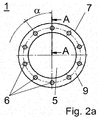
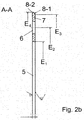
- FIG. 2a is a hole circle reinforcement according to the invention 1 and in the FIG. 2b a cross section on a line AA through the in FIG. 2a shown hole circle reinforcement 1 shown.
- the in the FIG. 2a shown hole circle reinforcement 1 has a central bore 5 and circularly arranged around the central bore 5 holes 6.
- the holes 6 are for receiving, in the FIG. 2a Not shown, fixing means, such as screws, suitable, with which the hole circle reinforcement 1 with the rim plate 2 and / or the Achsflansch 4 is connectable.
- the in the FIG. 2a shown hole circle reinforcement 1 has 10 holes 6, which are arranged at an angle ⁇ of 36 °.
- the hole circle reinforcement 1 has eight or a different number of holes 6.
- the Indian FIG. 2b shown cross-section of the hole circle reinforcement 1 on the line AA has at its outer edge a rounded edge 8-1 and an edge 8-2, which forms a right angle.
- connection dimensions (such as inner diameter, pitch circle diameter and outer diameter) are specified on the tractor side and, if applicable, according to DIN 74361, and should be carried out accordingly. Exemplary is in the FIG. 2b a version suitable for standard wheel connection 10x335x281x24 cyl. shown according to DIN 74361-3. But it is also possible to produce the hole circle reinforcement 1 in different proportions.
- the distance E 1 from the center of the hole circle amplification 1 up to the edge of the central hole 5 is for example 281 mm (center hole / center hole), the distance E 2 to the center of the bore 6 335 mm (pitch circle diameter / bolt hole circle), distance E 3 to Beginning of the rounding of the edge 8-1 385 mm and the distance E 4 to the outer edge 7 395 mm.
- the thickness of the disc 9 may vary, since it depends on the length of the stud (s) present on the vehicle. However, the thickness of the disc 9 should be at least 5 mm, otherwise the effect of the radius 8-1 would be lost.
- the hole circle reinforcement 1 is suitably made of steel.
- the material from which the disc 9 is made is at least S355J2G3 in terms of yield strength.
- the friction-increasing (surface) coating 10 improves the transmission of the drive component.
- the hole circle reinforcement 1 can be both completely provided with a surface coating 10 or roughened as well as only partially. Thus, embodiments are conceivable in which only the locations of the hole circle reinforcement 1 have a surface with increased friction, which come into contact with the rim disk 2 or the axle flange 4.
- the hole circle reinforcement 1 has a surface coating on only one side of the disk 9 (Traction coating) 10 or a rough / textured surface.
- Suitable surface coatings 10 are, for example, coatings which consist of a lacquer which contains particles such as sand particles and which produce an increased frictional resistance when the lacquer is dried after application and thus the surface coating 10 is made durable.
- coatings which consist of a lacquer which contains particles such as sand particles and which produce an increased frictional resistance when the lacquer is dried after application and thus the surface coating 10 is made durable.
- plastic coatings for example of rubber-like materials.
- the surface coating 10 of the hole circle reinforcement 1 or the disk 9 takes place, for example, according to the plasma coating system PC 430.
Landscapes
- Engineering & Computer Science (AREA)
- Mechanical Engineering (AREA)
- Connection Of Plates (AREA)
Applications Claiming Priority (1)
| Application Number | Priority Date | Filing Date | Title |
|---|---|---|---|
| DE102015103679.7A DE102015103679A1 (de) | 2015-03-13 | 2015-03-13 | Lochkreisverstärkung |
Publications (1)
| Publication Number | Publication Date |
|---|---|
| EP3069896A1 true EP3069896A1 (fr) | 2016-09-21 |
Family
ID=55527363
Family Applications (1)
| Application Number | Title | Priority Date | Filing Date |
|---|---|---|---|
| EP16159598.8A Withdrawn EP3069896A1 (fr) | 2015-03-13 | 2016-03-10 | Cercle de boulonnage renforcé |
Country Status (2)
| Country | Link |
|---|---|
| EP (1) | EP3069896A1 (fr) |
| DE (1) | DE102015103679A1 (fr) |
Citations (4)
| Publication number | Priority date | Publication date | Assignee | Title |
|---|---|---|---|---|
| US3759576A (en) * | 1971-10-18 | 1973-09-18 | Crager Ind Inc | Custom wheel assembly |
| DE4215072A1 (de) * | 1992-03-05 | 1993-09-09 | Remotec Dieter Wipperfuerth Gm | Felgenrad, das in felgenpartie und radschuessel bezueglich durchmesser, breite, form und anordnung von unterschiedlichen fahrzeugen passend zuzuordnen ist |
| US5362134A (en) * | 1992-01-31 | 1994-11-08 | Federico Carmona | Motor-vehicle wheel |
| EP0888909A2 (fr) * | 1997-06-30 | 1999-01-07 | Rüdiger Höffken | Adapteur de moyeu en forme de disque |
Family Cites Families (4)
| Publication number | Priority date | Publication date | Assignee | Title |
|---|---|---|---|---|
| DE278833C (fr) * | ||||
| DE2235619A1 (de) * | 1972-07-20 | 1974-01-31 | Kloeckner Humboldt Deutz Ag | Treib- und/oder laufrad fuer kraftfahrzeuge |
| DE9417707U1 (de) * | 1994-11-04 | 1995-08-17 | H & R Spezialfedern GmbH & Co.KG., 57368 Lennestadt | Radschraube mit Einschraubsicherung |
| DE102007020891A1 (de) * | 2007-05-04 | 2008-11-13 | Knorr-Bremse Systeme für Schienenfahrzeuge GmbH | Bremsscheibe und Verfahren zur Herstellung einer Bremsscheibe |
-
2015
- 2015-03-13 DE DE102015103679.7A patent/DE102015103679A1/de not_active Withdrawn
-
2016
- 2016-03-10 EP EP16159598.8A patent/EP3069896A1/fr not_active Withdrawn
Patent Citations (4)
| Publication number | Priority date | Publication date | Assignee | Title |
|---|---|---|---|---|
| US3759576A (en) * | 1971-10-18 | 1973-09-18 | Crager Ind Inc | Custom wheel assembly |
| US5362134A (en) * | 1992-01-31 | 1994-11-08 | Federico Carmona | Motor-vehicle wheel |
| DE4215072A1 (de) * | 1992-03-05 | 1993-09-09 | Remotec Dieter Wipperfuerth Gm | Felgenrad, das in felgenpartie und radschuessel bezueglich durchmesser, breite, form und anordnung von unterschiedlichen fahrzeugen passend zuzuordnen ist |
| EP0888909A2 (fr) * | 1997-06-30 | 1999-01-07 | Rüdiger Höffken | Adapteur de moyeu en forme de disque |
Also Published As
| Publication number | Publication date |
|---|---|
| DE102015103679A1 (de) | 2016-09-15 |
Similar Documents
| Publication | Publication Date | Title |
|---|---|---|
| EP1978264A2 (fr) | Dispositif de serrage forcé et son procédé de fabrication | |
| DE102016209846A1 (de) | Keilsicherungsmutteranordnung | |
| EP2794285B1 (fr) | Disque de roue destiné à un véhicule ferroviaire | |
| DE102015102739A1 (de) | Radmutter und mutterdeckel mit drehbegrenzung | |
| DE102011051980A1 (de) | Radzentralverschluss | |
| EP3113960B1 (fr) | Élément de fixation | |
| DE102008051601A1 (de) | Vorrichtung zur Befestigung einer Fahrzeugfelge an einer Radnabe eines Fahrzeuges | |
| DE2039925C3 (de) | Vorrichtung zum Befestigen einer Vielzahl von Schleifscheiben auf einer Schleifspindel | |
| DE102005059247B4 (de) | Bremsvorrichtung | |
| EP3069896A1 (fr) | Cercle de boulonnage renforcé | |
| DE102007034198B4 (de) | Lenkradschloß | |
| DE102012011609A1 (de) | Unterlegelement zur Befestigung eines Abgaskrümmers an einem Verbrennungsmotor, Abgaskrümmer und Verbrennungsmotor | |
| EP1903219B1 (fr) | Dispositif pour la fixation d'un composant sur un élément de support | |
| DE3224929A1 (de) | Faserverstaerktes fahrzeug-kunststoffrad und verfahren zu seiner herstellung | |
| DE102020105883A1 (de) | Bauteilanordnung | |
| DE102005026720A1 (de) | Scheibenbremse für ein Landfahrzeug | |
| DE102008031709A1 (de) | Scheibenbremsanordnung für ein Fahrzeug, insbesondere für ein Nutzfahrzeug | |
| DE102004005800A1 (de) | Naben-Segmentzentrierung | |
| DE202017103551U1 (de) | Reibringkörper, Reibringsatz zur Anordnung an den Radsteg eines Schienenrads, sowie Schienenradbremse | |
| EP2815145A1 (fr) | Mâchoire de frein à tambour | |
| DE202007014532U1 (de) | Kupplungsteil aus einem metallischen Scheibenkörper und einer im Spritzgußverfahren angebrachten Kunststoffnabe | |
| EP1335144A1 (fr) | Ensemble de support de frein | |
| EP1419078A1 (fr) | Servofrein automobile a depression protege contre les chocs | |
| EP2610117B1 (fr) | Système de fixation pour un entraînement d'essuie-glace d'un véhicule automobile | |
| DE102008061220B4 (de) | System zum Befestigen wenigstens einer weiteren Komponente an einer Kurbelwelle einer Brennkraftmaschine |
Legal Events
| Date | Code | Title | Description |
|---|---|---|---|
| PUAI | Public reference made under article 153(3) epc to a published international application that has entered the european phase |
Free format text: ORIGINAL CODE: 0009012 |
|
| AK | Designated contracting states |
Kind code of ref document: A1 Designated state(s): AL AT BE BG CH CY CZ DE DK EE ES FI FR GB GR HR HU IE IS IT LI LT LU LV MC MK MT NL NO PL PT RO RS SE SI SK SM TR |
|
| AX | Request for extension of the european patent |
Extension state: BA ME |
|
| RIN1 | Information on inventor provided before grant (corrected) |
Inventor name: KRINKE, MARTIN |
|
| STAA | Information on the status of an ep patent application or granted ep patent |
Free format text: STATUS: THE APPLICATION IS DEEMED TO BE WITHDRAWN |
|
| 18D | Application deemed to be withdrawn |
Effective date: 20170322 |