EP3069936B1 - Vorrichtung, die eine trittstufe eines kraftfahrzeugs bildet - Google Patents
Vorrichtung, die eine trittstufe eines kraftfahrzeugs bildet Download PDFInfo
- Publication number
- EP3069936B1 EP3069936B1 EP16305090.9A EP16305090A EP3069936B1 EP 3069936 B1 EP3069936 B1 EP 3069936B1 EP 16305090 A EP16305090 A EP 16305090A EP 3069936 B1 EP3069936 B1 EP 3069936B1
- Authority
- EP
- European Patent Office
- Prior art keywords
- movable plate
- cavity
- vehicle
- body element
- rotation
- Prior art date
- Legal status (The legal status is an assumption and is not a legal conclusion. Google has not performed a legal analysis and makes no representation as to the accuracy of the status listed.)
- Active
Links
Images


Classifications
-
- B—PERFORMING OPERATIONS; TRANSPORTING
- B60—VEHICLES IN GENERAL
- B60R—VEHICLES, VEHICLE FITTINGS, OR VEHICLE PARTS, NOT OTHERWISE PROVIDED FOR
- B60R3/00—Arrangements of steps or ladders facilitating access to or on the vehicle, e.g. running-boards
-
- B—PERFORMING OPERATIONS; TRANSPORTING
- B60—VEHICLES IN GENERAL
- B60R—VEHICLES, VEHICLE FITTINGS, OR VEHICLE PARTS, NOT OTHERWISE PROVIDED FOR
- B60R19/00—Wheel guards; Radiator guards, e.g. grilles; Obstruction removers; Fittings damping bouncing force in collisions
- B60R19/02—Bumpers, i.e. impact receiving or absorbing members for protecting vehicles or fending off blows from other vehicles or objects
- B60R19/48—Bumpers, i.e. impact receiving or absorbing members for protecting vehicles or fending off blows from other vehicles or objects combined with, or convertible into, other devices or objects, e.g. bumpers combined with road brushes, bumpers convertible into beds
-
- B—PERFORMING OPERATIONS; TRANSPORTING
- B60—VEHICLES IN GENERAL
- B60R—VEHICLES, VEHICLE FITTINGS, OR VEHICLE PARTS, NOT OTHERWISE PROVIDED FOR
- B60R21/00—Arrangements or fittings on vehicles for protecting or preventing injuries to occupants or pedestrians in case of accidents or other traffic risks
- B60R21/34—Protecting non-occupants of a vehicle, e.g. pedestrians
Definitions
- the present invention relates to a step device comprising a bodywork element, in particular a shield of a motor vehicle, a cavity formed in the bodywork element delimited by a lower wall forming a bearing surface for an anterior portion of the foot of the body. 'an user.
- a van or utility type motor vehicle conventionally comprises steps arranged on each side, each step having a cavity in the front bumper, to allow a user to climb towards the windshield to remove frost or accumulated snow on it.
- the step must have sufficient rigidity to support the weight of a user.
- the shield must also meet the "ECE127" regulation applicable to pedestrian impact, in particular the "shin shock". This regulation assumes that the shield has a sufficiently soft contact zone to deform and locally absorb the shock in contact with a leg. Steps must therefore satisfy conflicting needs.
- the document DE 10 2013 007 379 A1 discloses a step according to the preamble of claim 1.
- the invention aims to overcome all or part of the aforementioned drawbacks by providing a step device satisfying both the rigidity function expected to support the full weight of a person, the need for flexibility of the shield in case of shock.
- X is the longitudinal direction of the front-rear of the vehicle, directed towards the rear
- Y is the direction transverse to the vehicle , directed to the right and Z the vertical direction directed upwards.
- Front-to-back concepts refer to the direction of normal operation of the vehicle that is directed forward.
- the term “substantially” indicates that a slight deviation is allowed with respect to a given nominal position or disposition, while remaining within the scope of the invention.
- substantially vertical indicates that a difference of the order of 10 ° relative to a strictly vertical orientation is allowed within the scope of the invention.
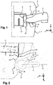
- FIG. 1 and 2 a device forming a step according to the invention, seen respectively from the side and from above.
- This device comprises a bodywork element 1 of a motor vehicle, typically a front bumper of the vehicle.
- This body element 1 comprises a cavity 2 delimited by a bottom wall 3 oriented substantially horizontally forming a bearing surface for an anterior portion of the foot 4 of a user.
- the cavity 2 is further defined by an upper wall 5 and a bottom wall 6 closing the inside of the cavity 2 and providing a junction of the bottom wall 3 and the top wall 5 with an external front surface 7 of the body element 1.
- the bottom wall 6 has a top view in the form of a bowl whose edges are connected to the outer end surface 7, which is typically oriented substantially vertically in the vicinity of the cavity 2. According to FIG.
- the step device comprises a movable plate 8 articulated on a structural element 9 of the vehicle, between a deployed position below the bottom wall 3 towards the bodywork element 1 (visible at figure 1-5 ), and a retracted position opposite the bodywork element 1 (as visible in FIG. figure 6 ).
- the deployed position is located at an advanced position relative to the retracted position, which is located further back towards the rear of the vehicle.
- the displacement of the movable plate 8 towards the retracted position is carried out under the constraint of the bodywork element 1 locally undergoing a deformation following an impact, typically a pedestrian impact in which the leg of a pedestrian 10, schematically represented by a circle to the figure 6 is struck by the bodywork element 1.
- the movable plate 8 is articulated about a substantially vertical axis of rotation Z1 carried by a structural element 9 of the vehicle.
- This structural element 9 is typically constituted by a front zone of a longitudinal member 11 of the vehicle or by an end of a front cross member 12 of the vehicle.
- the front cross member 12 which extends essentially in the direction transverse Y of the vehicle is connected at its lateral ends to the front ends of longitudinal members 11 of the vehicle, the longitudinal members 11 constituting structural elements which are oriented substantially in the longitudinal direction X of the vehicle.
- the axis of rotation Z1 of the movable plate 8 is therefore located on the inside of the vehicle, that is to say on the side of the median longitudinal vertical plane of the vehicle.
- the movable plate 8 is oriented substantially horizontally and is supported by a substantially vertical rear wall 13 connected to the axis of rotation Z1.
- the movable plate 8 and the rear wall 13 are typically made of elements from sheet metal assembled-welded or shaped by folding from a single piece of metal to obtain the general shape of a square. Rigidification conformations (not shown), such as locally deformed zones by stamping may be provided in the folding zone or in other areas of the plate 8 or the rear wall 13.
- the movable plate 8 and the rear wall 13 have a thickness of the order of 2.5 mm.
- the rear wall 13 provides the support function of the movable plate 8 and is connected to the structural element 9 by a hinge shown exploded at the figure 7 .
- the axis of rotation Z1 is materialized by a cylindrical axis whose diameter is of the order of 8 mm by way of non-limiting example. This cylindrical axis passes through the structural element 9 in a median zone of the articulation, considered vertically, as well as the rear wall 13 in the upper and lower zones of the articulation, bordering vertically the structural element 9.
- the movable plate 8 is shaped to withstand a vertical load of 120kg applied in the vertical direction Z.
- return means 14 are arranged on the axis of rotation Z1 and are shaped to return by default the movable plate 8 in the deployed position in the direction of the bodywork element 1.
- "Default” means “naturally” i.e., in the absence of opposite stress applied to the movable plate 8.
- abutment means are provided to limit the displacement of the movable plate 8 in the deployed position. Whatever its angular position about the axis of rotation Z1, the movable plate 8 remains below the bottom wall 3 of the cavity 2, at a distance of between 0.5 and 5 mm, which allows a mounting of the plate mobile 8 on the structural element 9, 11, 12 without conflict with the body member 1 and is sufficient clearance to allow movement of the movable plate 8 without obstacle.
- the movable plate 8 is advanced towards the bodywork element 1 over a length at least equal to half the depth of the cavity 2, measured longitudinally in a central region of the cavity 2, which is aligned with a notional plane P substantially corresponding to the longitudinal median plane of the foot of a person engaging in the cavity 2. This plane is parallel to the longitudinal direction X of the vehicle.
- the movable plate 8 is advanced towards the bodywork element 1 over a length substantially equal to two-thirds of the depth of the cavity 2 measured along the fictional plane P.
- the lower wall 3 When a user engages its foot in the cavity and relies on the lower surface 3 to rise and reach for example the windshield of the vehicle, the lower wall 3 locally deforms down under the force due to the weight of the user, until it comes to cooperate in contact with the movable plate 8 disposed under it in the deployed position.
- the deformation of the lower surface 3 of the cavity 2 is of the order of a few millimeters and corresponds to the functional space formed above the movable plate 8 to allow its mounting and pivoting in case of pedestrian impact.
Landscapes
- Engineering & Computer Science (AREA)
- Mechanical Engineering (AREA)
- Body Structure For Vehicles (AREA)
Claims (8)
- Vorrichtung, die eine Trittstufe bildet, die ein Karosserieelement (1) eines Kraftfahrzeugs enthält, wobei ein im Karosserieelement (1) ausgebildeter Hohlraum (2), der von einer unteren Wand (3) begrenzt wird, eine Auflagefläche für einen vorderen Teil des Fußes (4) eines Benutzers bildet, dadurch gekennzeichnet, dass der Hohlraum (2) außerdem von einer oberen Wand (5) und von einer Rückwand (6) begrenzt wird, die einen Innenraum des Hohlraums (2) verschließen, und dass die Vorrichtung eine gelenkig mit einem Strukturelement (9, 11, 12) des Fahrzeugs verbundene Platte (8) enthält, die zwischen einer ausgeklappten Stellung unter der unteren Wand (3) in Richtung des Karosserieelements (1) und einer eingeklappten Stellung entgegengesetzt zum Karosserieelement (1) beweglich ist, wobei die Verschiebung der beweglichen Platte (8) in die eingeklappte Stellung unter der Belastung des Karosserieelements (1) durchgeführt wird, das nach einem Aufprall eine Verformung erfährt.
- Vorrichtung nach Anspruch 1, dadurch gekennzeichnet, dass die bewegliche Platte (8) um eine im Wesentlichen senkrechte Drehachse (Z1) angelenkt ist, die von einem Strukturelement (9, 11, 12) des Fahrzeugs getragen wird, insbesondere einem vorderen Bereich eines Längsträgers (11) des Fahrzeugs oder einem vorderen Querträger (12) des Fahrzeugs.
- Vorrichtung nach Anspruch 2, dadurch gekennzeichnet, dass die bewegliche Platte (8) im Wesentlichen waagrecht ausgerichtet ist und von einer im Wesentlichen senkrechten hinteren Wand (13) gestützt wird, die mit der Drehachse (Z1) verbunden ist.
- Vorrichtung nach Anspruch 2 oder 3, dadurch gekennzeichnet, dass Rückstelleinrichtungen (14) auf der Drehachse (Z1) angeordnet und gestaltet sind, um die bewegliche Platte (8) in die ausgeklappte Stellung zurückzuholen.
- Vorrichtung nach Anspruch 4, dadurch gekennzeichnet, dass Anschlageinrichtungen vorgesehen sind, um die Verschiebung der beweglichen Platte (8) in die ausgeklappte Stellung zu begrenzen.
- Vorrichtung nach einem der Ansprüche 3 bis 5, dadurch gekennzeichnet, dass die bewegliche Platte (8) unter der unteren Wand (3) des Hohlraums (2) in einem Abstand zwischen 0,5 und 5 mm angeordnet ist.
- Vorrichtung nach einem der vorhergehenden Ansprüche, dadurch gekennzeichnet, dass die bewegliche Platte (8) in der ausgeklappten Stellung in Richtung des Karosserieelements (1) über eine Länge vorgeschoben wird, die mindestens gleich der Hälfte der Tiefe des Hohlraums (2) ist, gemessen in Längsrichtung in einer zentralen Zone des Hohlraums (2).
- Kraftfahrzeug, dadurch gekennzeichnet, dass es eine Vorrichtung nach einem der vorhergehenden Ansprüche enthält.
Applications Claiming Priority (1)
| Application Number | Priority Date | Filing Date | Title |
|---|---|---|---|
| FR1552102A FR3033764B1 (fr) | 2015-03-16 | 2015-03-16 | Dispositif formant marchepied d'un vehicule automobile |
Publications (2)
| Publication Number | Publication Date |
|---|---|
| EP3069936A1 EP3069936A1 (de) | 2016-09-21 |
| EP3069936B1 true EP3069936B1 (de) | 2017-11-22 |
Family
ID=53366050
Family Applications (1)
| Application Number | Title | Priority Date | Filing Date |
|---|---|---|---|
| EP16305090.9A Active EP3069936B1 (de) | 2015-03-16 | 2016-01-29 | Vorrichtung, die eine trittstufe eines kraftfahrzeugs bildet |
Country Status (2)
| Country | Link |
|---|---|
| EP (1) | EP3069936B1 (de) |
| FR (1) | FR3033764B1 (de) |
Families Citing this family (1)
| Publication number | Priority date | Publication date | Assignee | Title |
|---|---|---|---|---|
| FR3139787B1 (fr) | 2022-09-19 | 2024-08-02 | Renault Sas | Dispositif formant marchepied d’un véhicule automobile |
Family Cites Families (2)
| Publication number | Priority date | Publication date | Assignee | Title |
|---|---|---|---|---|
| DE3826542A1 (de) * | 1988-08-04 | 1990-02-08 | Man Nutzfahrzeuge Ag | Einstieg zum fahrerhaus eines nutzfahrzeuges |
| DE29900510U1 (de) * | 1999-01-14 | 1999-08-12 | Haslbeck Technik GmbH, 84453 Mühldorf | Trägerkonstruktion zur Befestigung eines Formteils an einer Fahrzeugkarosserie |
-
2015
- 2015-03-16 FR FR1552102A patent/FR3033764B1/fr not_active Expired - Fee Related
-
2016
- 2016-01-29 EP EP16305090.9A patent/EP3069936B1/de active Active
Non-Patent Citations (1)
| Title |
|---|
| None * |
Also Published As
| Publication number | Publication date |
|---|---|
| FR3033764B1 (fr) | 2017-03-03 |
| EP3069936A1 (de) | 2016-09-21 |
| FR3033764A1 (fr) | 2016-09-23 |
Similar Documents
| Publication | Publication Date | Title |
|---|---|---|
| FR2780927A1 (fr) | Dispositif de fixation des crosses d'un pare-chocs sur une aile de carrosserie de vehicule | |
| FR2858798A1 (fr) | Traverse de face avant technique d'un vehicule automobile, face avant technique et support de module de refroidissement munis d'une telle traverse | |
| EP3061696B1 (de) | Zuschnitt für die herstellung einer verpackung mindestens eines scheibenwischers, verpackung und verfahren zur herstellung einer solchen verpackung | |
| EP2186686A1 (de) | Verschiebungsvorrichtung eines starren Elements und mit einer solchen Vorrichtung ausgestattetes Fahrzeug | |
| FR3047037B1 (fr) | Poignee affleurante avec fonction push-pull pour ouvrant de vehicule automobile | |
| FR3063699A1 (fr) | Agencement de maintien d'un bac de coffre a l'avant d'une structure de caisse d'un vehicule automobile. | |
| EP3197722B1 (de) | Anordnung eines bodens in einem gepäckablagefach eines kraftfahrzeugs mit zurückziehbaren sitzen | |
| FR3051728A1 (fr) | Doublure interne de volet arriere | |
| EP3069936A1 (de) | Vorrichtung, die eine trittstufe eines kraftfahrzeugs bildet | |
| EP2783922B1 (de) | Stoßfänger für Kraftfahrzeug | |
| EP1901946B1 (de) | Kotflügel eines kraftfahrzeugs mit verformbarem abdichtungsschott | |
| WO2015189500A1 (fr) | Insert métallique pour moyen de remorquage de véhicule | |
| WO2015104467A1 (fr) | Véhicule doté d'un élément d'absorption de choc | |
| EP1252045B1 (de) | Vorrichtung zur befestigung der seitenschenkel einer stossstange | |
| FR2987335A1 (fr) | Boite a eau de vehicule automobile pouvant absorber une partie de l'energie d'un choc pieton et structure avant correspondante | |
| EP3359422B1 (de) | Schublade in einem kraftfahrzeug integriert | |
| EP3969710B1 (de) | Überlastpuffer für kraftfahrzeughaube | |
| EP3210821B1 (de) | Endstück für profil, das einen querschnittsabschnitt in u-form umfasst | |
| EP1288075A1 (de) | Starrer Belag für eine Trittstufe und Trittbrett mit diesem Belag | |
| EP2616285B1 (de) | Fahrzeug zur abdämpfung eines fussgängeraufpralls | |
| EP4037957A1 (de) | Seitenaufpralldämpfer für ein kraftfahrzeug | |
| FR3040677A1 (fr) | Agencement d'un passage de roue d'un vehicule automobile | |
| FR3024852A1 (fr) | Agencement de fixation d'une poignee de virage d'un vehicule automobile | |
| FR2987011A1 (fr) | Absorbeur de choc destine a etre fixe sur la poutre transversale avant superieure d'un vehicule automobile | |
| FR2970051A1 (fr) | Dispositif de fixation par clippage, a paroi deformable, pour la solidarisation/desolidarisation d'un premier organe a un second organe |
Legal Events
| Date | Code | Title | Description |
|---|---|---|---|
| PUAI | Public reference made under article 153(3) epc to a published international application that has entered the european phase |
Free format text: ORIGINAL CODE: 0009012 |
|
| AK | Designated contracting states |
Kind code of ref document: A1 Designated state(s): AL AT BE BG CH CY CZ DE DK EE ES FI FR GB GR HR HU IE IS IT LI LT LU LV MC MK MT NL NO PL PT RO RS SE SI SK SM TR |
|
| AX | Request for extension of the european patent |
Extension state: BA ME |
|
| 17P | Request for examination filed |
Effective date: 20161220 |
|
| RBV | Designated contracting states (corrected) |
Designated state(s): AL AT BE BG CH CY CZ DE DK EE ES FI FR GB GR HR HU IE IS IT LI LT LU LV MC MK MT NL NO PL PT RO RS SE SI SK SM TR |
|
| GRAP | Despatch of communication of intention to grant a patent |
Free format text: ORIGINAL CODE: EPIDOSNIGR1 |
|
| RIC1 | Information provided on ipc code assigned before grant |
Ipc: B60R 19/48 20060101ALI20170519BHEP Ipc: B60R 3/00 20060101AFI20170519BHEP |
|
| INTG | Intention to grant announced |
Effective date: 20170620 |
|
| GRAS | Grant fee paid |
Free format text: ORIGINAL CODE: EPIDOSNIGR3 |
|
| GRAA | (expected) grant |
Free format text: ORIGINAL CODE: 0009210 |
|
| AK | Designated contracting states |
Kind code of ref document: B1 Designated state(s): AL AT BE BG CH CY CZ DE DK EE ES FI FR GB GR HR HU IE IS IT LI LT LU LV MC MK MT NL NO PL PT RO RS SE SI SK SM TR |
|
| REG | Reference to a national code |
Ref country code: GB Ref legal event code: FG4D Free format text: NOT ENGLISH |
|
| REG | Reference to a national code |
Ref country code: CH Ref legal event code: EP |
|
| REG | Reference to a national code |
Ref country code: IE Ref legal event code: FG4D Free format text: LANGUAGE OF EP DOCUMENT: FRENCH |
|
| REG | Reference to a national code |
Ref country code: AT Ref legal event code: REF Ref document number: 948086 Country of ref document: AT Kind code of ref document: T Effective date: 20171215 |
|
| REG | Reference to a national code |
Ref country code: DE Ref legal event code: R096 Ref document number: 602016000889 Country of ref document: DE |
|
| REG | Reference to a national code |
Ref country code: FR Ref legal event code: PLFP Year of fee payment: 3 |
|
| REG | Reference to a national code |
Ref country code: NL Ref legal event code: MP Effective date: 20171122 |
|
| REG | Reference to a national code |
Ref country code: LT Ref legal event code: MG4D |
|
| REG | Reference to a national code |
Ref country code: AT Ref legal event code: MK05 Ref document number: 948086 Country of ref document: AT Kind code of ref document: T Effective date: 20171122 |
|
| PG25 | Lapsed in a contracting state [announced via postgrant information from national office to epo] |
Ref country code: FI Free format text: LAPSE BECAUSE OF FAILURE TO SUBMIT A TRANSLATION OF THE DESCRIPTION OR TO PAY THE FEE WITHIN THE PRESCRIBED TIME-LIMIT Effective date: 20171122 Ref country code: NL Free format text: LAPSE BECAUSE OF FAILURE TO SUBMIT A TRANSLATION OF THE DESCRIPTION OR TO PAY THE FEE WITHIN THE PRESCRIBED TIME-LIMIT Effective date: 20171122 Ref country code: NO Free format text: LAPSE BECAUSE OF FAILURE TO SUBMIT A TRANSLATION OF THE DESCRIPTION OR TO PAY THE FEE WITHIN THE PRESCRIBED TIME-LIMIT Effective date: 20180222 Ref country code: SE Free format text: LAPSE BECAUSE OF FAILURE TO SUBMIT A TRANSLATION OF THE DESCRIPTION OR TO PAY THE FEE WITHIN THE PRESCRIBED TIME-LIMIT Effective date: 20171122 Ref country code: ES Free format text: LAPSE BECAUSE OF FAILURE TO SUBMIT A TRANSLATION OF THE DESCRIPTION OR TO PAY THE FEE WITHIN THE PRESCRIBED TIME-LIMIT Effective date: 20171122 Ref country code: LT Free format text: LAPSE BECAUSE OF FAILURE TO SUBMIT A TRANSLATION OF THE DESCRIPTION OR TO PAY THE FEE WITHIN THE PRESCRIBED TIME-LIMIT Effective date: 20171122 |
|
| PG25 | Lapsed in a contracting state [announced via postgrant information from national office to epo] |
Ref country code: LV Free format text: LAPSE BECAUSE OF FAILURE TO SUBMIT A TRANSLATION OF THE DESCRIPTION OR TO PAY THE FEE WITHIN THE PRESCRIBED TIME-LIMIT Effective date: 20171122 Ref country code: AT Free format text: LAPSE BECAUSE OF FAILURE TO SUBMIT A TRANSLATION OF THE DESCRIPTION OR TO PAY THE FEE WITHIN THE PRESCRIBED TIME-LIMIT Effective date: 20171122 Ref country code: GR Free format text: LAPSE BECAUSE OF FAILURE TO SUBMIT A TRANSLATION OF THE DESCRIPTION OR TO PAY THE FEE WITHIN THE PRESCRIBED TIME-LIMIT Effective date: 20180223 Ref country code: BG Free format text: LAPSE BECAUSE OF FAILURE TO SUBMIT A TRANSLATION OF THE DESCRIPTION OR TO PAY THE FEE WITHIN THE PRESCRIBED TIME-LIMIT Effective date: 20180222 Ref country code: HR Free format text: LAPSE BECAUSE OF FAILURE TO SUBMIT A TRANSLATION OF THE DESCRIPTION OR TO PAY THE FEE WITHIN THE PRESCRIBED TIME-LIMIT Effective date: 20171122 Ref country code: RS Free format text: LAPSE BECAUSE OF FAILURE TO SUBMIT A TRANSLATION OF THE DESCRIPTION OR TO PAY THE FEE WITHIN THE PRESCRIBED TIME-LIMIT Effective date: 20171122 |
|
| PG25 | Lapsed in a contracting state [announced via postgrant information from national office to epo] |
Ref country code: CZ Free format text: LAPSE BECAUSE OF FAILURE TO SUBMIT A TRANSLATION OF THE DESCRIPTION OR TO PAY THE FEE WITHIN THE PRESCRIBED TIME-LIMIT Effective date: 20171122 Ref country code: CY Free format text: LAPSE BECAUSE OF FAILURE TO SUBMIT A TRANSLATION OF THE DESCRIPTION OR TO PAY THE FEE WITHIN THE PRESCRIBED TIME-LIMIT Effective date: 20171122 Ref country code: DK Free format text: LAPSE BECAUSE OF FAILURE TO SUBMIT A TRANSLATION OF THE DESCRIPTION OR TO PAY THE FEE WITHIN THE PRESCRIBED TIME-LIMIT Effective date: 20171122 Ref country code: EE Free format text: LAPSE BECAUSE OF FAILURE TO SUBMIT A TRANSLATION OF THE DESCRIPTION OR TO PAY THE FEE WITHIN THE PRESCRIBED TIME-LIMIT Effective date: 20171122 Ref country code: SK Free format text: LAPSE BECAUSE OF FAILURE TO SUBMIT A TRANSLATION OF THE DESCRIPTION OR TO PAY THE FEE WITHIN THE PRESCRIBED TIME-LIMIT Effective date: 20171122 |
|
| REG | Reference to a national code |
Ref country code: DE Ref legal event code: R097 Ref document number: 602016000889 Country of ref document: DE |
|
| PG25 | Lapsed in a contracting state [announced via postgrant information from national office to epo] |
Ref country code: SM Free format text: LAPSE BECAUSE OF FAILURE TO SUBMIT A TRANSLATION OF THE DESCRIPTION OR TO PAY THE FEE WITHIN THE PRESCRIBED TIME-LIMIT Effective date: 20171122 Ref country code: RO Free format text: LAPSE BECAUSE OF FAILURE TO SUBMIT A TRANSLATION OF THE DESCRIPTION OR TO PAY THE FEE WITHIN THE PRESCRIBED TIME-LIMIT Effective date: 20171122 Ref country code: PL Free format text: LAPSE BECAUSE OF FAILURE TO SUBMIT A TRANSLATION OF THE DESCRIPTION OR TO PAY THE FEE WITHIN THE PRESCRIBED TIME-LIMIT Effective date: 20171122 |
|
| PG25 | Lapsed in a contracting state [announced via postgrant information from national office to epo] |
Ref country code: MT Free format text: LAPSE BECAUSE OF FAILURE TO SUBMIT A TRANSLATION OF THE DESCRIPTION OR TO PAY THE FEE WITHIN THE PRESCRIBED TIME-LIMIT Effective date: 20171122 |
|
| PLBE | No opposition filed within time limit |
Free format text: ORIGINAL CODE: 0009261 |
|
| STAA | Information on the status of an ep patent application or granted ep patent |
Free format text: STATUS: NO OPPOSITION FILED WITHIN TIME LIMIT |
|
| 26N | No opposition filed |
Effective date: 20180823 |
|
| PG25 | Lapsed in a contracting state [announced via postgrant information from national office to epo] |
Ref country code: LU Free format text: LAPSE BECAUSE OF NON-PAYMENT OF DUE FEES Effective date: 20180129 |
|
| REG | Reference to a national code |
Ref country code: IE Ref legal event code: MM4A |
|
| REG | Reference to a national code |
Ref country code: BE Ref legal event code: MM Effective date: 20180131 |
|
| PG25 | Lapsed in a contracting state [announced via postgrant information from national office to epo] |
Ref country code: BE Free format text: LAPSE BECAUSE OF NON-PAYMENT OF DUE FEES Effective date: 20180131 Ref country code: SI Free format text: LAPSE BECAUSE OF FAILURE TO SUBMIT A TRANSLATION OF THE DESCRIPTION OR TO PAY THE FEE WITHIN THE PRESCRIBED TIME-LIMIT Effective date: 20171122 |
|
| PG25 | Lapsed in a contracting state [announced via postgrant information from national office to epo] |
Ref country code: IE Free format text: LAPSE BECAUSE OF NON-PAYMENT OF DUE FEES Effective date: 20180129 |
|
| PG25 | Lapsed in a contracting state [announced via postgrant information from national office to epo] |
Ref country code: MC Free format text: LAPSE BECAUSE OF FAILURE TO SUBMIT A TRANSLATION OF THE DESCRIPTION OR TO PAY THE FEE WITHIN THE PRESCRIBED TIME-LIMIT Effective date: 20171122 |
|
| REG | Reference to a national code |
Ref country code: CH Ref legal event code: PL |
|
| PG25 | Lapsed in a contracting state [announced via postgrant information from national office to epo] |
Ref country code: LI Free format text: LAPSE BECAUSE OF NON-PAYMENT OF DUE FEES Effective date: 20190131 Ref country code: CH Free format text: LAPSE BECAUSE OF NON-PAYMENT OF DUE FEES Effective date: 20190131 |
|
| PG25 | Lapsed in a contracting state [announced via postgrant information from national office to epo] |
Ref country code: TR Free format text: LAPSE BECAUSE OF FAILURE TO SUBMIT A TRANSLATION OF THE DESCRIPTION OR TO PAY THE FEE WITHIN THE PRESCRIBED TIME-LIMIT Effective date: 20171122 |
|
| PG25 | Lapsed in a contracting state [announced via postgrant information from national office to epo] |
Ref country code: PT Free format text: LAPSE BECAUSE OF FAILURE TO SUBMIT A TRANSLATION OF THE DESCRIPTION OR TO PAY THE FEE WITHIN THE PRESCRIBED TIME-LIMIT Effective date: 20171122 |
|
| PG25 | Lapsed in a contracting state [announced via postgrant information from national office to epo] |
Ref country code: MK Free format text: LAPSE BECAUSE OF NON-PAYMENT OF DUE FEES Effective date: 20171122 Ref country code: HU Free format text: LAPSE BECAUSE OF FAILURE TO SUBMIT A TRANSLATION OF THE DESCRIPTION OR TO PAY THE FEE WITHIN THE PRESCRIBED TIME-LIMIT; INVALID AB INITIO Effective date: 20160129 |
|
| PG25 | Lapsed in a contracting state [announced via postgrant information from national office to epo] |
Ref country code: AL Free format text: LAPSE BECAUSE OF FAILURE TO SUBMIT A TRANSLATION OF THE DESCRIPTION OR TO PAY THE FEE WITHIN THE PRESCRIBED TIME-LIMIT Effective date: 20171122 Ref country code: IS Free format text: LAPSE BECAUSE OF FAILURE TO SUBMIT A TRANSLATION OF THE DESCRIPTION OR TO PAY THE FEE WITHIN THE PRESCRIBED TIME-LIMIT Effective date: 20180322 |
|
| P01 | Opt-out of the competence of the unified patent court (upc) registered |
Effective date: 20230608 |
|
| PGFP | Annual fee paid to national office [announced via postgrant information from national office to epo] |
Ref country code: GB Payment date: 20260123 Year of fee payment: 11 |
|
| PGFP | Annual fee paid to national office [announced via postgrant information from national office to epo] |
Ref country code: DE Payment date: 20260121 Year of fee payment: 11 |
|
| PGFP | Annual fee paid to national office [announced via postgrant information from national office to epo] |
Ref country code: IT Payment date: 20260126 Year of fee payment: 11 |
|
| PGFP | Annual fee paid to national office [announced via postgrant information from national office to epo] |
Ref country code: FR Payment date: 20260123 Year of fee payment: 11 |