EP3070204A1 - Dispositif et procede d'adduction d'eau a partir d'une fontaine - Google Patents
Dispositif et procede d'adduction d'eau a partir d'une fontaine Download PDFInfo
- Publication number
- EP3070204A1 EP3070204A1 EP16000501.3A EP16000501A EP3070204A1 EP 3070204 A1 EP3070204 A1 EP 3070204A1 EP 16000501 A EP16000501 A EP 16000501A EP 3070204 A1 EP3070204 A1 EP 3070204A1
- Authority
- EP
- European Patent Office
- Prior art keywords
- tube
- well
- full
- filter
- filter tube
- Prior art date
- Legal status (The legal status is an assumption and is not a legal conclusion. Google has not performed a legal analysis and makes no representation as to the accuracy of the status listed.)
- Granted
Links
Images


Classifications
-
- E—FIXED CONSTRUCTIONS
- E02—HYDRAULIC ENGINEERING; FOUNDATIONS; SOIL SHIFTING
- E02D—FOUNDATIONS; EXCAVATIONS; EMBANKMENTS; UNDERGROUND OR UNDERWATER STRUCTURES
- E02D19/00—Keeping dry foundation sites or other areas in the ground
- E02D19/06—Restraining of underground water
- E02D19/10—Restraining of underground water by lowering level of ground water
-
- E—FIXED CONSTRUCTIONS
- E03—WATER SUPPLY; SEWERAGE
- E03B—INSTALLATIONS OR METHODS FOR OBTAINING, COLLECTING, OR DISTRIBUTING WATER
- E03B3/00—Methods or installations for obtaining or collecting drinking water or tap water
- E03B3/06—Methods or installations for obtaining or collecting drinking water or tap water from underground
- E03B3/08—Obtaining and confining water by means of wells
- E03B3/12—Obtaining and confining water by means of wells by means of vertical pipe wells
-
- E—FIXED CONSTRUCTIONS
- E03—WATER SUPPLY; SEWERAGE
- E03B—INSTALLATIONS OR METHODS FOR OBTAINING, COLLECTING, OR DISTRIBUTING WATER
- E03B3/00—Methods or installations for obtaining or collecting drinking water or tap water
- E03B3/06—Methods or installations for obtaining or collecting drinking water or tap water from underground
- E03B3/08—Obtaining and confining water by means of wells
- E03B3/16—Component parts of wells
- E03B3/18—Well filters
-
- Y—GENERAL TAGGING OF NEW TECHNOLOGICAL DEVELOPMENTS; GENERAL TAGGING OF CROSS-SECTIONAL TECHNOLOGIES SPANNING OVER SEVERAL SECTIONS OF THE IPC; TECHNICAL SUBJECTS COVERED BY FORMER USPC CROSS-REFERENCE ART COLLECTIONS [XRACs] AND DIGESTS
- Y02—TECHNOLOGIES OR APPLICATIONS FOR MITIGATION OR ADAPTATION AGAINST CLIMATE CHANGE
- Y02A—TECHNOLOGIES FOR ADAPTATION TO CLIMATE CHANGE
- Y02A20/00—Water conservation; Efficient water supply; Efficient water use
Definitions
- the invention relates to a device for conveying water from a well for dewatering or water lowering in a civil engineering structure, according to the preamble of claim 1.
- the invention also relates to a corresponding method for conveying water from such a fountain according to the preamble of claim 12 ,
- Fig. 10 is a longitudinal sectional view through a conventional device shown by means of which water from a well 2 can be promoted.
- the well 2 has a bore 4, which is filled after introduction of the device with a special gravel with a predetermined grain size.
- an annular space fill 5 is formed, namely in the annular space between an outer peripheral surface of the device and an edge of the bore 4.
- a sound barrier layer 6 is provided within the bore 4, in a predetermined axial depth thereof.
- the device comprises an elongated slot tube 8, which is usually made of PVC plastic.
- a plurality of axially extending slots 9 are formed, which allow entry of water radially from the outside into the slot tube 8.
- the annular space fill 5 serves as a filter for the radially inflowing from the outside water.
- a pumping device 18 is arranged, which is connected to a connecting line 20 is connected.
- This connection line 20 passes through the slot tube 8 through to a surface, wherein in Fig. 10
- only portions of the connection line 20 are shown at the very bottom and at the very top.
- a separate level tube 30 is further introduced into the bore 4 of the well 2, by means of which a level of the groundwater, which adjusts during operation of the pumping device 18, can be measured.
- the pumping device 18 can be controlled as a function of the detected with the level tube 30 level of groundwater.
- the conventional device according to the Fig. 10 works in such a way that water from the region of the well, which lies vertically below the clay barrier layer 6, radially enters the slot pipe 8 from the outside. Then, the water within the slotted tube 8 then falls vertically downwards in the direction of the pumping device 18, as indicated by the vertically downwardly directed arrows in the Fig. 10 is symbolized within the slotted tube 8.
- Such a flow of the water within the slit pipe 8 has the disadvantage that in this case the water is enriched as a result of turbulence with oxygen, and thereby forms iron hydroxide. Due to the oxygen dissolved in the water, the machine parts or components which are flowed through by the pumped-out water regularly become obstructed.
- Affected by this are, for example, the pumping device 18 and the connecting line 20 connected thereto. After a certain operating time, it is necessary, because of the forming obstructions, to either clean the soiled machine parts or components costly or even completely replace them. In addition to the great effort required for this, this also leads to the disadvantage that then the operation of the device for pumping water from the well 2 must be interrupted.
- Another disadvantage of a conventional device according to the Fig. 10 is that the axial slots 9, which are formed in the PVC slot tube 8, can be clogged by grains, sand, sediments or the like. This is due to a constant distance, the opposing walls of the slots 9 in the radial direction of a PVC slot tube 8 have.
- the invention has for its object to optimize a device and a method for pumping water from a well for dewatering or water lowering in a civil engineering structure in terms of increased efficiency.
- a device serves for pumping or pumping off water from a well for water retention or water lowering in a civil engineering structure, and comprises at least one elongated solid tube, which can be introduced vertically into a bore of the well. Furthermore, the device comprises at least one filter tube made of stainless steel, which is designed in the form of a winding wire filter and is connected to a lower side of the solid tube, and a pumping device, by means of which water which flows radially from the outside through the filter tube, can be pumped out.
- a diameter of the filter tube is chosen smaller than a diameter of the full tube.
- the full tube can be made of stainless steel.
- a solid tube is to be understood as a cylindrical tube, which is hollow on the inside and in its wall or peripheral surface has no openings, recesses or the like. In that regard, it is not possible with such a full pipe, that water enters radially from the outside through its peripheral surface into the interior of the tube.
- the invention is based on the essential knowledge that at least the filter tube, and preferably also the solid tube, are made of stainless steel. In this way, the stability of the device compared to conventionally known devices, which are usually made of PVC pipes, substantially increased and allows multiple installation and removal in or well wells. As a result, the life of a device according to the invention can be considerably increased, whereby a multiple use of the device can be realized at various sites.
- an advantageous embodiment of the well bore results in that an annulus adjacent to the filter tube has a greater radial extent than an annulus adjacent to the full pipe.
- a footprint on which the pumping device is mounted may be formed within the full tube, a footprint on which the pumping device is mounted.
- this footprint can be arranged adjacent to the lower end face of the full tube, and is formed in the simplest case by a region of the lower end face. This creates a “step” that is used to hold the pumping device.
- the pumping device remains within the full tube, namely on the just mentioned contact patch on the lower end side of the full tube. This advantageously minimizes the assembly effort when handling the device.
- the filter tube in the form of a winding wire filter, it is possible that water flows radially from the outside into the filter tube, and is then pumped out of the well by the adjoining pumping device axially upwards to the surface.
- an essential feature here is that the water to be pumped can only enter radially from the outside through the filter tube, but not radially from the outside through the full tube.
- the water flows in an area of the well bore that is vertically below a clay barrier layer of the well, along an outer peripheral surface of the solid tube, and through an annulus of the well vertically down toward the filter tube.
- the water to be pumped is thus for the most part conveyed vertically along the outer circumferential surface of the solid tube and then enters the filter tube radially from the outside.
- a uniform flow of water is ensured and at the same time prevents turbulence of the water and a release of oxygen therein, whereby the hitherto prevailing Problem of obstruction of the pumping device and the connected pipe elements no longer exists.
- a device is used as explained above, wherein water flows during operation of the pumping means radially from the outside into the filter tube and then pumped through the at least one full pipe from the well.
- water flows through an annulus of the well vertically downwards in the direction of the filter tube, before it enters the filter tube radially from the outside.
- a diameter of the filter tube is smaller than a diameter of the full tube, so that the annular space of the well adjacent to the at least one filter tube of the device compared to the annular space of the well adjacent to the at least one full tube of the device a larger radial Has extension.
- this corresponds to an axial length section, in which the at least one solid tube of the device runs vertically below the sound barrier layer in the bore of the well, a multiple of the diameter of the solid tube.
- Fig. 1 shows a simplified side view of a device 1 according to the invention and its essential components.
- the device 1 comprises at least one full tube 10, and at least one filter tube 12, which is connected to a lower end face 16 of the full tube 10.
- the filter tube 12 is connected to the bottom tube 10 shown at the bottom, namely in such a way that a hydraulic connection between the interior of the filter tube 12 and the full tube 10 is made.
- water can flow from the filter tube 12 into the full tube 10.
- further solid tubes 10 can be connected or fastened.
- a total axial length of the device 1 is defined by the plurality of solid tubes 10, which are fastened together with their end faces, in connection with the filter tube 12, which is connected to the lowest tube 10 arranged at the bottom.
- the device 1 comprises a pump device 18, which is arranged within the solid tube 10.
- the pumping device 18 is connected to a connecting line 20 which is guided through the full tube 10 at an upper end side of the device 1 to the outside.
- a connecting line 20 which is guided through the full tube 10 at an upper end side of the device 1 to the outside.
- the filter tube 12 has a smaller diameter compared to the adjacent full tube 10.
- a contact surface 22 is formed on a lower end face 16 of the solid tube 10, on which the pumping device 18 is arranged.
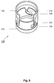
- several Aufsitzblöcke 23 are mounted on the footprint 22, on which the pumping device 18 is seated with its underside. This Aufsitzblöcke 23 cause water from the filter tube 12 can flow up into the full tube 10, wherein the water flows around the bottom of the pumping device 18 evenly and then in the inlet region 18 E enters ( Fig. 3 ).
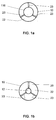
- Fig. 1a shows a simplified sectional view taken along the line II of Fig. 1 , This illustrates a sitting of the pumping device 18 on the Aufsitzblöcken 23rd
- Fig. 1 b shows a plan view of the footprint 22 within the full tube 10, wherein the pumping device 18 is omitted for simplicity. It can be seen that the Aufsitzblöcke 23 radially from the mouth of the filter tube 12 extend to the outer edge of the solid tube 10, and so far form a stable support surface for the pumping device 18.
- a lifting cap 24 can be attached with connecting means 26.
- the connecting means 26 may be formed, for example, in the form of a ring eye or the like, and serve for the purpose that a sickle hook or the like is attached thereto. Accordingly, it is possible to hold the device 1 with the lifting cap 24 or to apply a pulling force to the device 1 in its longitudinal axis L, e.g. for a withdrawal of the device 1 from a well bore.
- radial spacers 28 On an outer circumferential surface of the respective solid tubes 10 radial spacers 28 may be attached. The purpose of these radial spacers 28 will be explained in detail below.
- Fig. 2 shows a simplified schematic longitudinal sectional view through a well 2 and a bore 4 of this well, in which the device 1 according to Fig. 1 is introduced.
- the annular space that forms between the outer peripheral surface 11 of the solid tubes 10 and the bore 4 is filled with filter gravel, whereby an annulus 5 is formed.
- a sound barrier layer 6 is provided in a predetermined axial depth of the bore 4, which is formed by swelling clay particles.
- the device 1 can be used centered within the bore 4 thanks to the radial spacers 28.
- the advantage here is when a level tube 30 is attached to the radial spacers 28 and in this case runs parallel to the solid tubes 10. In this way, the device 1 with its solid tubes 10 and the level tube 30 form a unit which can be - together for the purpose of a simplified installation - introduced into the bore 4 of the well 2.
- the connecting line 20 is connected to the pumping device 18, which extends through the solid tubes 10 upwards and out of the well 2 out to a surface. Accordingly, during operation of the pump device 18, water can be discharged from the well 2 through the connection line 20.
- the axial length sections A V and A F are in Fig. 2 marked accordingly.
- the filter tube 12 is made of a stainless steel winding wire filter.
- a diameter D 12 of the filter tube 12 is smaller than a diameter D 10 of the full tube 10.
- a radial extent of filter gravel within the bore 4 adjacent the filter tube 12 is greater than the radial extent of filter gravel adjacent the full tube 10 has the consequence that water, before it actually enters the filter tube 12, flows through a longer distance at the filter gravel and is thereby cleaned more.
- a curved arrow that water from the interior of the filter tube 12 can flow upwards into the full tube 10.
- the water, after it has entered the full tube 10, in the radial direction uniformly flows past the Aufsitzblöcken 23 and then enters the inlet region 18 E of the pumping device 18.
- the configuration of the filter tube 12 in the form of a winding wire filter is in the Fig. 4 which illustrates a simplified cross-sectional view of a wall of the filter tube 12.
- the filter tube 12 has along its longitudinal axis L a plurality of winding wires 14 which are arranged spaced apart from each other.
- the individual winding wires 14 are each in a plane E, which is perpendicular to the longitudinal axis L of the device 1, and each extending along the circumference of the filter tube 12.
- the winding wires 14 are each attached to supporting webs 15 and attached, which extend parallel to the longitudinal axis L of the device 1.
- Fig. 4 only the right part of a filter tube 12 is shown.
- the edge regions of the winding wires 14 are formed such that a passage D F between each two adjacent winding wires 14 increases radially inwardly.
- the passage D F has radially inwardly an opening angle ⁇ of 90 °.
- Such an embodiment of the passage D F with a radially inwardly increasing opening angle ⁇ has the result that sand grains, sediments or the like can only settle between the winding wires 14 to a slight extent or not at all and thereby block clogging of the filter tube 12 by such particles is. Accordingly, a uniformly constant and high water flow rate is ensured for the filter tube 12 during operation of the device 1.
- the edge regions of opposite winding wires 14 may also be formed such that the opening angle of the passage D F formed therebetween assumes values other than 90 °, for example of at least 45 °, more preferably of at least 60 °. In any case, this opening angle ⁇ should increase radially inward, so that as explained clogging of the passages D F between the winding wires 14 by sediments or the like does not occur.
- passages D F between the winding wires 14 of the filter tube 12 should be pointed out that in this case the nature of the filter tube 12 made of stainless steel, has an advantageous effect in such a way that ensures a sufficiently high stability for the winding wires 14 and a uniform spacing therebetween for a constant passage D F is ensured. Furthermore, this also simplifies cleaning of the filter tube 12 for maintenance or the like possible, without damaging the winding wires 14.
- An advantageous length proportion of the device 1, according to which the filter tube 12 has a comparatively small axial length, can be further defined by the Axialinab mustard A F , in which the at least one filter tube is provided, a maximum of ten times (10 times) value, preferably a maximum of five times (5 times) value, and more preferably at most twice the value of the diameter D 12 of the filter tube 12 corresponds.
- a desired minimum flow rate of water, which is to flow radially from the outside into the filter tube 12 can be compensated with a reduced axial length of the filter tube 12 by correspondingly large passages D F between the winding wires 14 of the filter tube 12.
- the device 1 along its longitudinal axis L can have a plurality of solid tubes 10, which are connected to one another at their front sides. In this way, it is possible to realize for the device a large axial length section A V in which the full tubes 10 are provided.
- the joining of a plurality of solid tubes 10 may be effected by a system 100 in which at least one holding element 114 is formed on a tube element 110 on a wall adjacent to its end face. Furthermore, in the case of a second tubular element 112, such a system provides a slotted guide 116, which is formed in the region of a wall of the second tubular element 112 and adjacent to its end face.
- tube elements 110, 112 it can be assumed that these can be respective full tubes 10 of the device 1.
- the tubular elements 110, 112 are in the Fig. 5 shown in a side view, namely with their opposite end faces 110 s , 112 s .
- the retaining element 114 is formed on the wall of the first tubular element 110 adjacent to its end face 110 s , namely on its inner circumferential surface. Accordingly, the holding element 114 is not visible from the outside and in Fig. 5 indicated by dashed lines.
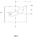
- the second tube element 112 is in the Fig. 6 shown separately in a side view, namely with its end face 112 s .
- the link guide 116 is formed in the wall of the second tubular element 112, and has a total of three sections I, II and III.
- the first section I is open adjacent to the end face 112 s and extends parallel to the longitudinal axis L of the second tubular element 112.
- the second section II adjoins the first section I and extends obliquely to the longitudinal axis L of the second tubular element 112.
- the third section III connects to the second section II and extends transversely to the longitudinal axis of the second tubular element 112.
- the sliding guide 116 is formed in the wall of the second tubular element 112 is in the wall of this tubular element a corresponding recess 118 is formed. Furthermore, the third section III of the slide guide 116 comprises a detent recess 120, the function of which will be explained in detail below.
- the view after Fig. 5 illustrates that the first tubular element 110 has a diameter D 1 on its end face 110 s .
- the second tubular element 112 has a diameter D 2 on its end face 112 s .
- the dimensions of the tubular elements 110, 112 at their end faces are chosen such that the relationship applies: D 2 ⁇ D 1 . Because the diameter D 2 of the end face 112 s of the second tubular element 112 is greater than the diameter D 1 of the end face 110 s of the first tubular element 110, the first tubular element 110 can be plugged onto the second tubular element 112 with its end face 110 s .
- This mating of the two tube elements, whereby the first tube element 110 is mounted on the second tube element 112 is in the Fig. 5 symbolized by the arrow M.
- Fig. 7 shows the two tube elements 110, 112 of Fig. 5 in a perspective view.
- first tube element 110 On the first tube element 110, three holding elements 114 are formed on the inner circumferential surface thereof, which are spaced apart uniformly along the circumference of the first tube element 110.
- three slide guides 116 are also provided on the second tube element 112, namely along the circumference of the second holding element 112 at a uniform distance from one another.
- Fig. 7 is symbolized by the arrow M, a mounting of the first tube member 110 to the second tube member 112.
- the two tube elements 110, 112 are initially positioned coaxially with each other, wherein, for example, the first tube element 110 above the second tube element 112 is positioned and the holding elements 114 of the first tube member 110 are each aligned with the first portions I of the respective slotted guides 116 of the second tube member 112.
- Starting from the in Fig. 7 shown starting position of the two tubular elements 110, 112 can then be made connecting these tubular elements in such a way that the first tube member 110 is moved in the direction of the second tube member 112 and is lowered onto the second tube member 112.
- FIG. 7-9 Through the perspective views of Fig. 7-9 the sequence of an assembly of the two pipe elements 110, 112 is shown at their end faces. As soon as the end face 110 s of the first tube element 110 engages over the end face 112 s of the second tube element 112, the holding elements 114 enter the first section I of the respective slide guides 116 of the second tube element 112 ( Fig. 8 ). Subsequently, the holding elements 114 pass automatically through the second section II of the respective slide guides 116 into the third section III thereof (FIG. Fig. 9 ).
- the holding elements 114 are located in the third section III of the slide guides 116, it can be effected by further rotation of the tube elements 110, 112 relative to each other, that the holding elements 114 are received in the respective locking recesses 120 and engage there.
- the two tube elements 110, 112 are then secured both axially relative to one another, ie in the direction of their longitudinal axis L, as well as against an automatic rotation relative to one another. In this way, a reliable connection of the two tube elements 110, 112 is ensured at its opposite end faces 110 s , 112 s .
- latching webs 126 (FIG. Fig. 5 ) be formed on the outer peripheral surfaces of the first and second tubular elements 110, 112, latching webs 126 (FIG. Fig. 5 ) be formed on the outer peripheral surfaces of the first and second tubular elements 110, 112, latching webs 126 (FIG. Fig. 5 ) be formed.
- These locking bars 126 are used in conjunction with a (not shown) tool for the purpose that the tube elements 110, 112, after the holding elements 114 have passed into the third section III of the slide guides 116 during assembly, can be rotated relative to each other, so that then engage the retaining elements 114 as explained in the locking recesses 120.
- a moment about the longitudinal axis L of the tubular elements 110, 112 can be generated by means of a suitable tool and in interaction with the locking webs 126.
- the spacers 28 (FIG. Fig. 1 ) can be positively connected to the locking webs 126, wherein the locking webs 126 may have a suitable
- a spacer element in the form of an O-ring 124 (see. Fig. 5 ) between the tubular elements 110, 112, namely within a groove which can form between the tubular elements 110, 112 in the region of its outer peripheral surface.
- a release of the two tube elements 110, 112 can be based on the in Fig. 9 state shown in a simple manner by the tube elements 110, 112 are rotated relative to each other about its longitudinal axis L such that the holding elements 114 disengage from the locking recesses 120.
- the O-ring 124 is previously removed from the groove between the two pipe elements, for example by means of a suitable tool in the form of a hook or the like.
- the holding elements then slide 114 through the third section III and the second section II of the respective slotted guides 116 to the first section I.
- the tubular elements 110, 112 axially, ie along its longitudinal axis L are moved away from each other.
- the holding elements 114 then move outward out of the first section I of the respective slide guides 116, as a result of which the tube elements 110, 112 can be completely detached from one another.
- tubular elements 110, 112 can either be connected to one another at their front sides or also detached from one another again, it is thus possible for the device 1 according to the invention to connect a plurality of solid tubes 10 at their end faces in order to provide for the device 1 to achieve the largest possible Axialinabêt A V.
- the full tubes 10 can be solved as described again from each other or dismantled. As a result, for example, a transport of individual full tubes 10 on vehicles or the like is simplified.
- connection and disconnection of tubular elements 110, 112 also applies to the device 1 according to the invention for connecting a plurality of filter tubes 12, if a correspondingly large axial length section A F , in which the filter tube 12 is to be provided, should be necessary for a particular purpose of the device 1.
Landscapes
- Engineering & Computer Science (AREA)
- Life Sciences & Earth Sciences (AREA)
- Hydrology & Water Resources (AREA)
- Environmental & Geological Engineering (AREA)
- Water Supply & Treatment (AREA)
- Public Health (AREA)
- Health & Medical Sciences (AREA)
- General Life Sciences & Earth Sciences (AREA)
- Mining & Mineral Resources (AREA)
- Paleontology (AREA)
- Civil Engineering (AREA)
- General Engineering & Computer Science (AREA)
- Structural Engineering (AREA)
- Filtration Of Liquid (AREA)
Priority Applications (1)
| Application Number | Priority Date | Filing Date | Title |
|---|---|---|---|
| PL16000501T PL3070204T3 (pl) | 2015-03-17 | 2016-03-02 | Urządzenie i sposób tłoczenia wody ze studni |
Applications Claiming Priority (2)
| Application Number | Priority Date | Filing Date | Title |
|---|---|---|---|
| DE102015003375 | 2015-03-17 | ||
| DE102015006093.7A DE102015006093B3 (de) | 2015-03-17 | 2015-05-09 | Vorrichtung und Verfahren zum Fördern von Wasser aus einem Brunnen |
Publications (2)
| Publication Number | Publication Date |
|---|---|
| EP3070204A1 true EP3070204A1 (fr) | 2016-09-21 |
| EP3070204B1 EP3070204B1 (fr) | 2020-05-06 |
Family
ID=56577362
Family Applications (1)
| Application Number | Title | Priority Date | Filing Date |
|---|---|---|---|
| EP16000501.3A Active EP3070204B1 (fr) | 2015-03-17 | 2016-03-02 | Dispositif et procédé d'adduction d'eau à partir d'une fontaine |
Country Status (4)
| Country | Link |
|---|---|
| EP (1) | EP3070204B1 (fr) |
| DE (1) | DE102015006093B3 (fr) |
| DK (1) | DK3070204T3 (fr) |
| PL (1) | PL3070204T3 (fr) |
Cited By (4)
| Publication number | Priority date | Publication date | Assignee | Title |
|---|---|---|---|---|
| CN111980042A (zh) * | 2020-08-28 | 2020-11-24 | 中国铁建大桥工程局集团有限公司 | 一种深基坑高承压水井及其施工方法 |
| CN112281882A (zh) * | 2020-10-25 | 2021-01-29 | 中铁十二局集团有限公司 | 一种基底涌水涌砂处理方法 |
| CN114016529A (zh) * | 2021-11-25 | 2022-02-08 | 中铁十四局集团大盾构工程有限公司 | 一种隧道基坑用降水排水装置 |
| CN115094929A (zh) * | 2022-07-07 | 2022-09-23 | 中煤长江基础建设有限公司 | 一种管井降水排水设备及其排水方法 |
Families Citing this family (4)
| Publication number | Priority date | Publication date | Assignee | Title |
|---|---|---|---|---|
| DE102019100948B4 (de) | 2018-12-03 | 2022-06-09 | Hölscher Wasserbau GmbH | Vorrichtung zur Gewinnung von Wasser und zur Übertragung von Energie |
| CN110925018B (zh) * | 2019-12-02 | 2021-06-25 | 河南科技大学 | 隧道联络通道内的泵房施工方法及泵房施工降水系统 |
| CN113463671B (zh) * | 2021-07-06 | 2022-07-22 | 泰州新润辰建设工程有限公司 | 一种降水井及降水施工方法 |
| CN114108668B (zh) * | 2021-12-15 | 2022-10-21 | 中国五冶集团有限公司 | 一种深基坑自动降水系统 |
Citations (2)
| Publication number | Priority date | Publication date | Assignee | Title |
|---|---|---|---|---|
| DE19534882A1 (de) * | 1995-09-20 | 1997-03-27 | Abb Patent Gmbh | Verfahren zur Grundwasser- und Bodensanierung |
| DE202014105093U1 (de) | 2014-10-24 | 2015-02-12 | Kurt Hermann Beckert | Rohranordnung |
Family Cites Families (1)
| Publication number | Priority date | Publication date | Assignee | Title |
|---|---|---|---|---|
| DE202009007307U1 (de) * | 2009-05-05 | 2009-08-27 | Beckert Brunnentechnik Gmbh | Schweißverbindung an Wickeldrahtfiltern für Brunnenausbaurohre |
-
2015
- 2015-05-09 DE DE102015006093.7A patent/DE102015006093B3/de active Active
-
2016
- 2016-03-02 PL PL16000501T patent/PL3070204T3/pl unknown
- 2016-03-02 EP EP16000501.3A patent/EP3070204B1/fr active Active
- 2016-03-02 DK DK16000501.3T patent/DK3070204T3/da active
Patent Citations (2)
| Publication number | Priority date | Publication date | Assignee | Title |
|---|---|---|---|---|
| DE19534882A1 (de) * | 1995-09-20 | 1997-03-27 | Abb Patent Gmbh | Verfahren zur Grundwasser- und Bodensanierung |
| DE202014105093U1 (de) | 2014-10-24 | 2015-02-12 | Kurt Hermann Beckert | Rohranordnung |
Cited By (5)
| Publication number | Priority date | Publication date | Assignee | Title |
|---|---|---|---|---|
| CN111980042A (zh) * | 2020-08-28 | 2020-11-24 | 中国铁建大桥工程局集团有限公司 | 一种深基坑高承压水井及其施工方法 |
| CN111980042B (zh) * | 2020-08-28 | 2021-09-24 | 中国铁建大桥工程局集团有限公司 | 一种深基坑高承压水井及其施工方法 |
| CN112281882A (zh) * | 2020-10-25 | 2021-01-29 | 中铁十二局集团有限公司 | 一种基底涌水涌砂处理方法 |
| CN114016529A (zh) * | 2021-11-25 | 2022-02-08 | 中铁十四局集团大盾构工程有限公司 | 一种隧道基坑用降水排水装置 |
| CN115094929A (zh) * | 2022-07-07 | 2022-09-23 | 中煤长江基础建设有限公司 | 一种管井降水排水设备及其排水方法 |
Also Published As
| Publication number | Publication date |
|---|---|
| DE102015006093B3 (de) | 2016-08-25 |
| PL3070204T3 (pl) | 2020-11-02 |
| DK3070204T3 (da) | 2020-08-03 |
| EP3070204B1 (fr) | 2020-05-06 |
Similar Documents
| Publication | Publication Date | Title |
|---|---|---|
| DE102015006093B3 (de) | Vorrichtung und Verfahren zum Fördern von Wasser aus einem Brunnen | |
| DE2431516C3 (de) | Vorrichtung zur Abgabe von Fluiden | |
| DE1911745C3 (de) | Anschluß für einen Unterwasser-Bohrlochkopf | |
| DE69719811T2 (de) | Verfahren zum lancieren von mindestens einem stopfen in ein rohr im bohrloch | |
| DE1911697B2 (de) | Loesbare verbindung fuer der bohrpfahlherstellung dienende bohrrohre | |
| DE102011118099A1 (de) | Vorrichtung zum Verbinden zweier Leitungsabschnitte | |
| DE68916636T2 (de) | Unterirdisches rohr für ein vortriebsbohrverfahren und verbindungsstruktur eines derartigen rohres. | |
| DE102017119201A1 (de) | Steckverbinder und Rohrverbindung mit einem Steckverbinder | |
| DE202008014113U1 (de) | Vorrichtung zur Aktivierung oder Reinigung von Brunnen | |
| DE102009018383B4 (de) | Vorrichtung zum Aktivieren oder Reinigen von Filterrohrbrunnen | |
| EP3480419B1 (fr) | Dispositif formant tarière hélicoïdale et procédé de formation d'un dispositif formant tarière hélicoïdale | |
| DE1944686C3 (de) | Vorrichtung zum Einbringen eines Bohrloches in das Erdreich für ein Fundierungselement und Verfahren zum Betrieb der Vorrichtung | |
| DE3540870C2 (de) | Gewinde- oder Steckverbinder | |
| EP3070390B1 (fr) | Systeme et procede pour le raccordement d'elements de tuyaux | |
| EP3061875B1 (fr) | Dispositif et procede d'activation ou de nettoyage de puits | |
| EP2942474A1 (fr) | Couronne de forage dotée d'un certain nombre de trépans à molettes destinée au forage d'un terrain de fondation et procédé destiné à détacher d'un sabot de cuvelage foré une couronne de forage présentant un certain nombre de trépans à molettes destinée au forage d'un sol de construction | |
| DE10163981A1 (de) | Bohrrohr mit Verrastung | |
| WO2011153995A1 (fr) | Dispositif d'aspiration et procédé d'aspiration | |
| DE102013107153A1 (de) | Reinigungsschacht sowie Verfahren zur dezentralen Regenwasserbehandlung | |
| EP2757229B1 (fr) | Dispositif de mesure et procédé destiné à surveiller le colmatage d'un trou de forage | |
| EP2946061B1 (fr) | Dispositif d'évacuation de déblais de forage | |
| EP2952640A1 (fr) | Dispositif d'activation ou de nettoyage de puits | |
| DE10241610B4 (de) | Adapter zum Verbinden einer einzuziehenden Rohrleitung mit einer Zugvorrichtung | |
| EP4099525B1 (fr) | Dispositif et procédé d'introduction d'un dispositif supplementaire souterrain dans le sol | |
| EP3029263B1 (fr) | Dispositif de forage horizontal de la terre |
Legal Events
| Date | Code | Title | Description |
|---|---|---|---|
| PUAI | Public reference made under article 153(3) epc to a published international application that has entered the european phase |
Free format text: ORIGINAL CODE: 0009012 |
|
| AK | Designated contracting states |
Kind code of ref document: A1 Designated state(s): AL AT BE BG CH CY CZ DE DK EE ES FI FR GB GR HR HU IE IS IT LI LT LU LV MC MK MT NL NO PL PT RO RS SE SI SK SM TR |
|
| AX | Request for extension of the european patent |
Extension state: BA ME |
|
| STAA | Information on the status of an ep patent application or granted ep patent |
Free format text: STATUS: REQUEST FOR EXAMINATION WAS MADE |
|
| 17P | Request for examination filed |
Effective date: 20160901 |
|
| RBV | Designated contracting states (corrected) |
Designated state(s): AL AT BE BG CH CY CZ DE DK EE ES FI FR GB GR HR HU IE IS IT LI LT LU LV MC MK MT NL NO PL PT RO RS SE SI SK SM TR |
|
| STAA | Information on the status of an ep patent application or granted ep patent |
Free format text: STATUS: EXAMINATION IS IN PROGRESS |
|
| 17Q | First examination report despatched |
Effective date: 20191029 |
|
| REG | Reference to a national code |
Ref country code: DE Ref legal event code: R079 Ref document number: 502016009799 Country of ref document: DE Free format text: PREVIOUS MAIN CLASS: E02D0019100000 Ipc: E03B0003120000 |
|
| GRAP | Despatch of communication of intention to grant a patent |
Free format text: ORIGINAL CODE: EPIDOSNIGR1 |
|
| STAA | Information on the status of an ep patent application or granted ep patent |
Free format text: STATUS: GRANT OF PATENT IS INTENDED |
|
| GRAS | Grant fee paid |
Free format text: ORIGINAL CODE: EPIDOSNIGR3 |
|
| RIC1 | Information provided on ipc code assigned before grant |
Ipc: E03B 3/12 20060101AFI20200207BHEP Ipc: E03B 3/18 20060101ALI20200207BHEP |
|
| INTG | Intention to grant announced |
Effective date: 20200304 |
|
| GRAA | (expected) grant |
Free format text: ORIGINAL CODE: 0009210 |
|
| STAA | Information on the status of an ep patent application or granted ep patent |
Free format text: STATUS: THE PATENT HAS BEEN GRANTED |
|
| AK | Designated contracting states |
Kind code of ref document: B1 Designated state(s): AL AT BE BG CH CY CZ DE DK EE ES FI FR GB GR HR HU IE IS IT LI LT LU LV MC MK MT NL NO PL PT RO RS SE SI SK SM TR |
|
| REG | Reference to a national code |
Ref country code: GB Ref legal event code: FG4D Free format text: NOT ENGLISH |
|
| REG | Reference to a national code |
Ref country code: CH Ref legal event code: EP Ref country code: AT Ref legal event code: REF Ref document number: 1266923 Country of ref document: AT Kind code of ref document: T Effective date: 20200515 |
|
| REG | Reference to a national code |
Ref country code: IE Ref legal event code: FG4D Free format text: LANGUAGE OF EP DOCUMENT: GERMAN |
|
| REG | Reference to a national code |
Ref country code: DE Ref legal event code: R096 Ref document number: 502016009799 Country of ref document: DE |
|
| REG | Reference to a national code |
Ref country code: DK Ref legal event code: T3 Effective date: 20200728 |
|
| REG | Reference to a national code |
Ref country code: NL Ref legal event code: FP |
|
| REG | Reference to a national code |
Ref country code: LT Ref legal event code: MG4D |
|
| PG25 | Lapsed in a contracting state [announced via postgrant information from national office to epo] |
Ref country code: LT Free format text: LAPSE BECAUSE OF FAILURE TO SUBMIT A TRANSLATION OF THE DESCRIPTION OR TO PAY THE FEE WITHIN THE PRESCRIBED TIME-LIMIT Effective date: 20200506 Ref country code: FI Free format text: LAPSE BECAUSE OF FAILURE TO SUBMIT A TRANSLATION OF THE DESCRIPTION OR TO PAY THE FEE WITHIN THE PRESCRIBED TIME-LIMIT Effective date: 20200506 Ref country code: GR Free format text: LAPSE BECAUSE OF FAILURE TO SUBMIT A TRANSLATION OF THE DESCRIPTION OR TO PAY THE FEE WITHIN THE PRESCRIBED TIME-LIMIT Effective date: 20200807 Ref country code: NO Free format text: LAPSE BECAUSE OF FAILURE TO SUBMIT A TRANSLATION OF THE DESCRIPTION OR TO PAY THE FEE WITHIN THE PRESCRIBED TIME-LIMIT Effective date: 20200806 Ref country code: IS Free format text: LAPSE BECAUSE OF FAILURE TO SUBMIT A TRANSLATION OF THE DESCRIPTION OR TO PAY THE FEE WITHIN THE PRESCRIBED TIME-LIMIT Effective date: 20200906 Ref country code: SE Free format text: LAPSE BECAUSE OF FAILURE TO SUBMIT A TRANSLATION OF THE DESCRIPTION OR TO PAY THE FEE WITHIN THE PRESCRIBED TIME-LIMIT Effective date: 20200506 Ref country code: PT Free format text: LAPSE BECAUSE OF FAILURE TO SUBMIT A TRANSLATION OF THE DESCRIPTION OR TO PAY THE FEE WITHIN THE PRESCRIBED TIME-LIMIT Effective date: 20200907 |
|
| PG25 | Lapsed in a contracting state [announced via postgrant information from national office to epo] |
Ref country code: LV Free format text: LAPSE BECAUSE OF FAILURE TO SUBMIT A TRANSLATION OF THE DESCRIPTION OR TO PAY THE FEE WITHIN THE PRESCRIBED TIME-LIMIT Effective date: 20200506 Ref country code: RS Free format text: LAPSE BECAUSE OF FAILURE TO SUBMIT A TRANSLATION OF THE DESCRIPTION OR TO PAY THE FEE WITHIN THE PRESCRIBED TIME-LIMIT Effective date: 20200506 Ref country code: HR Free format text: LAPSE BECAUSE OF FAILURE TO SUBMIT A TRANSLATION OF THE DESCRIPTION OR TO PAY THE FEE WITHIN THE PRESCRIBED TIME-LIMIT Effective date: 20200506 Ref country code: BG Free format text: LAPSE BECAUSE OF FAILURE TO SUBMIT A TRANSLATION OF THE DESCRIPTION OR TO PAY THE FEE WITHIN THE PRESCRIBED TIME-LIMIT Effective date: 20200806 |
|
| PG25 | Lapsed in a contracting state [announced via postgrant information from national office to epo] |
Ref country code: AL Free format text: LAPSE BECAUSE OF FAILURE TO SUBMIT A TRANSLATION OF THE DESCRIPTION OR TO PAY THE FEE WITHIN THE PRESCRIBED TIME-LIMIT Effective date: 20200506 |
|
| PG25 | Lapsed in a contracting state [announced via postgrant information from national office to epo] |
Ref country code: EE Free format text: LAPSE BECAUSE OF FAILURE TO SUBMIT A TRANSLATION OF THE DESCRIPTION OR TO PAY THE FEE WITHIN THE PRESCRIBED TIME-LIMIT Effective date: 20200506 Ref country code: SM Free format text: LAPSE BECAUSE OF FAILURE TO SUBMIT A TRANSLATION OF THE DESCRIPTION OR TO PAY THE FEE WITHIN THE PRESCRIBED TIME-LIMIT Effective date: 20200506 Ref country code: CZ Free format text: LAPSE BECAUSE OF FAILURE TO SUBMIT A TRANSLATION OF THE DESCRIPTION OR TO PAY THE FEE WITHIN THE PRESCRIBED TIME-LIMIT Effective date: 20200506 Ref country code: ES Free format text: LAPSE BECAUSE OF FAILURE TO SUBMIT A TRANSLATION OF THE DESCRIPTION OR TO PAY THE FEE WITHIN THE PRESCRIBED TIME-LIMIT Effective date: 20200506 |
|
| REG | Reference to a national code |
Ref country code: DE Ref legal event code: R097 Ref document number: 502016009799 Country of ref document: DE |
|
| PG25 | Lapsed in a contracting state [announced via postgrant information from national office to epo] |
Ref country code: SK Free format text: LAPSE BECAUSE OF FAILURE TO SUBMIT A TRANSLATION OF THE DESCRIPTION OR TO PAY THE FEE WITHIN THE PRESCRIBED TIME-LIMIT Effective date: 20200506 |
|
| PLBE | No opposition filed within time limit |
Free format text: ORIGINAL CODE: 0009261 |
|
| STAA | Information on the status of an ep patent application or granted ep patent |
Free format text: STATUS: NO OPPOSITION FILED WITHIN TIME LIMIT |
|
| 26N | No opposition filed |
Effective date: 20210209 |
|
| PG25 | Lapsed in a contracting state [announced via postgrant information from national office to epo] |
Ref country code: SI Free format text: LAPSE BECAUSE OF FAILURE TO SUBMIT A TRANSLATION OF THE DESCRIPTION OR TO PAY THE FEE WITHIN THE PRESCRIBED TIME-LIMIT Effective date: 20200506 |
|
| PG25 | Lapsed in a contracting state [announced via postgrant information from national office to epo] |
Ref country code: MC Free format text: LAPSE BECAUSE OF FAILURE TO SUBMIT A TRANSLATION OF THE DESCRIPTION OR TO PAY THE FEE WITHIN THE PRESCRIBED TIME-LIMIT Effective date: 20200506 |
|
| REG | Reference to a national code |
Ref country code: CH Ref legal event code: PL |
|
| REG | Reference to a national code |
Ref country code: BE Ref legal event code: MM Effective date: 20210331 |
|
| PG25 | Lapsed in a contracting state [announced via postgrant information from national office to epo] |
Ref country code: IE Free format text: LAPSE BECAUSE OF NON-PAYMENT OF DUE FEES Effective date: 20210302 Ref country code: LU Free format text: LAPSE BECAUSE OF NON-PAYMENT OF DUE FEES Effective date: 20210302 Ref country code: LI Free format text: LAPSE BECAUSE OF NON-PAYMENT OF DUE FEES Effective date: 20210331 Ref country code: CH Free format text: LAPSE BECAUSE OF NON-PAYMENT OF DUE FEES Effective date: 20210331 |
|
| PG25 | Lapsed in a contracting state [announced via postgrant information from national office to epo] |
Ref country code: BE Free format text: LAPSE BECAUSE OF NON-PAYMENT OF DUE FEES Effective date: 20210331 |
|
| PG25 | Lapsed in a contracting state [announced via postgrant information from national office to epo] |
Ref country code: HU Free format text: LAPSE BECAUSE OF FAILURE TO SUBMIT A TRANSLATION OF THE DESCRIPTION OR TO PAY THE FEE WITHIN THE PRESCRIBED TIME-LIMIT; INVALID AB INITIO Effective date: 20160302 |
|
| PG25 | Lapsed in a contracting state [announced via postgrant information from national office to epo] |
Ref country code: CY Free format text: LAPSE BECAUSE OF FAILURE TO SUBMIT A TRANSLATION OF THE DESCRIPTION OR TO PAY THE FEE WITHIN THE PRESCRIBED TIME-LIMIT Effective date: 20200506 |
|
| P01 | Opt-out of the competence of the unified patent court (upc) registered |
Effective date: 20230526 |
|
| PG25 | Lapsed in a contracting state [announced via postgrant information from national office to epo] |
Ref country code: MK Free format text: LAPSE BECAUSE OF FAILURE TO SUBMIT A TRANSLATION OF THE DESCRIPTION OR TO PAY THE FEE WITHIN THE PRESCRIBED TIME-LIMIT Effective date: 20200506 |
|
| PG25 | Lapsed in a contracting state [announced via postgrant information from national office to epo] |
Ref country code: MT Free format text: LAPSE BECAUSE OF FAILURE TO SUBMIT A TRANSLATION OF THE DESCRIPTION OR TO PAY THE FEE WITHIN THE PRESCRIBED TIME-LIMIT Effective date: 20200506 |
|
| PGFP | Annual fee paid to national office [announced via postgrant information from national office to epo] |
Ref country code: IT Payment date: 20250331 Year of fee payment: 10 |
|
| PG25 | Lapsed in a contracting state [announced via postgrant information from national office to epo] |
Ref country code: TR Free format text: LAPSE BECAUSE OF FAILURE TO SUBMIT A TRANSLATION OF THE DESCRIPTION OR TO PAY THE FEE WITHIN THE PRESCRIBED TIME-LIMIT Effective date: 20200506 |
|
| PGFP | Annual fee paid to national office [announced via postgrant information from national office to epo] |
Ref country code: PL Payment date: 20251209 Year of fee payment: 11 |
|
| PGFP | Annual fee paid to national office [announced via postgrant information from national office to epo] |
Ref country code: GB Payment date: 20260324 Year of fee payment: 11 |
|
| PGFP | Annual fee paid to national office [announced via postgrant information from national office to epo] |
Ref country code: DE Payment date: 20260331 Year of fee payment: 11 Ref country code: DK Payment date: 20260323 Year of fee payment: 11 |
|
| PGFP | Annual fee paid to national office [announced via postgrant information from national office to epo] |
Ref country code: AT Payment date: 20260319 Year of fee payment: 11 |
|
| PGFP | Annual fee paid to national office [announced via postgrant information from national office to epo] |
Ref country code: RO Payment date: 20260224 Year of fee payment: 11 |
|
| PGFP | Annual fee paid to national office [announced via postgrant information from national office to epo] |
Ref country code: NL Payment date: 20260323 Year of fee payment: 11 |
|
| PGFP | Annual fee paid to national office [announced via postgrant information from national office to epo] |
Ref country code: FR Payment date: 20260324 Year of fee payment: 11 |