EP3070278A2 - Dispositif de protection pour turbomachine - Google Patents
Dispositif de protection pour turbomachine Download PDFInfo
- Publication number
- EP3070278A2 EP3070278A2 EP16156672.4A EP16156672A EP3070278A2 EP 3070278 A2 EP3070278 A2 EP 3070278A2 EP 16156672 A EP16156672 A EP 16156672A EP 3070278 A2 EP3070278 A2 EP 3070278A2
- Authority
- EP
- European Patent Office
- Prior art keywords
- ring
- protective device
- ring segments
- turbomachine
- circumferential direction
- Prior art date
- Legal status (The legal status is an assumption and is not a legal conclusion. Google has not performed a legal analysis and makes no representation as to the accuracy of the status listed.)
- Withdrawn
Links
- 230000001681 protective effect Effects 0.000 claims abstract description 51
- 229910010293 ceramic material Inorganic materials 0.000 claims description 9
- 229910010271 silicon carbide Inorganic materials 0.000 claims description 4
- HBMJWWWQQXIZIP-UHFFFAOYSA-N silicon carbide Chemical compound [Si+]#[C-] HBMJWWWQQXIZIP-UHFFFAOYSA-N 0.000 claims description 4
- 229910052574 oxide ceramic Inorganic materials 0.000 claims description 3
- 239000011226 reinforced ceramic Substances 0.000 claims description 3
- 230000008646 thermal stress Effects 0.000 claims description 3
- 230000000284 resting effect Effects 0.000 claims 3
- 239000000919 ceramic Substances 0.000 description 9
- 238000004519 manufacturing process Methods 0.000 description 9
- 239000000463 material Substances 0.000 description 7
- 239000000835 fiber Substances 0.000 description 5
- 238000009413 insulation Methods 0.000 description 5
- 230000035515 penetration Effects 0.000 description 5
- 239000002131 composite material Substances 0.000 description 4
- 230000003116 impacting effect Effects 0.000 description 4
- 230000000694 effects Effects 0.000 description 3
- 239000012634 fragment Substances 0.000 description 3
- 230000005540 biological transmission Effects 0.000 description 2
- 238000010276 construction Methods 0.000 description 2
- 239000002184 metal Substances 0.000 description 2
- 230000002093 peripheral effect Effects 0.000 description 2
- 239000011248 coating agent Substances 0.000 description 1
- 238000000576 coating method Methods 0.000 description 1
- 238000002485 combustion reaction Methods 0.000 description 1
- 238000011161 development Methods 0.000 description 1
- 230000018109 developmental process Effects 0.000 description 1
- 238000006073 displacement reaction Methods 0.000 description 1
- 238000000034 method Methods 0.000 description 1
- 229910052575 non-oxide ceramic Inorganic materials 0.000 description 1
- 239000011225 non-oxide ceramic Substances 0.000 description 1
- 239000011224 oxide ceramic Substances 0.000 description 1
- 239000002245 particle Substances 0.000 description 1
- 230000000149 penetrating effect Effects 0.000 description 1
- 230000002265 prevention Effects 0.000 description 1
- 230000002787 reinforcement Effects 0.000 description 1
Images

Classifications
-
- F—MECHANICAL ENGINEERING; LIGHTING; HEATING; WEAPONS; BLASTING
- F01—MACHINES OR ENGINES IN GENERAL; ENGINE PLANTS IN GENERAL; STEAM ENGINES
- F01D—NON-POSITIVE DISPLACEMENT MACHINES OR ENGINES, e.g. STEAM TURBINES
- F01D21/00—Shutting-down of machines or engines, e.g. in emergency; Regulating, controlling, or safety means not otherwise provided for
- F01D21/04—Shutting-down of machines or engines, e.g. in emergency; Regulating, controlling, or safety means not otherwise provided for responsive to undesired position of rotor relative to stator or to breaking-off of a part of the rotor, e.g. indicating such position
-
- F—MECHANICAL ENGINEERING; LIGHTING; HEATING; WEAPONS; BLASTING
- F01—MACHINES OR ENGINES IN GENERAL; ENGINE PLANTS IN GENERAL; STEAM ENGINES
- F01D—NON-POSITIVE DISPLACEMENT MACHINES OR ENGINES, e.g. STEAM TURBINES
- F01D21/00—Shutting-down of machines or engines, e.g. in emergency; Regulating, controlling, or safety means not otherwise provided for
- F01D21/04—Shutting-down of machines or engines, e.g. in emergency; Regulating, controlling, or safety means not otherwise provided for responsive to undesired position of rotor relative to stator or to breaking-off of a part of the rotor, e.g. indicating such position
- F01D21/045—Shutting-down of machines or engines, e.g. in emergency; Regulating, controlling, or safety means not otherwise provided for responsive to undesired position of rotor relative to stator or to breaking-off of a part of the rotor, e.g. indicating such position special arrangements in stators or in rotors dealing with breaking-off of part of rotor
-
- F—MECHANICAL ENGINEERING; LIGHTING; HEATING; WEAPONS; BLASTING
- F01—MACHINES OR ENGINES IN GENERAL; ENGINE PLANTS IN GENERAL; STEAM ENGINES
- F01D—NON-POSITIVE DISPLACEMENT MACHINES OR ENGINES, e.g. STEAM TURBINES
- F01D25/00—Component parts, details, or accessories, not provided for in, or of interest apart from, other groups
- F01D25/24—Casings; Casing parts, e.g. diaphragms, casing fastenings
-
- F—MECHANICAL ENGINEERING; LIGHTING; HEATING; WEAPONS; BLASTING
- F02—COMBUSTION ENGINES; HOT-GAS OR COMBUSTION-PRODUCT ENGINE PLANTS
- F02C—GAS-TURBINE PLANTS; AIR INTAKES FOR JET-PROPULSION PLANTS; CONTROLLING FUEL SUPPLY IN AIR-BREATHING JET-PROPULSION PLANTS
- F02C7/00—Features, components parts, details or accessories, not provided for in, or of interest apart form groups F02C1/00 - F02C6/00; Air intakes for jet-propulsion plants
- F02C7/04—Air intakes for gas-turbine plants or jet-propulsion plants
- F02C7/05—Air intakes for gas-turbine plants or jet-propulsion plants having provisions for obviating the penetration of damaging objects or particles
-
- F—MECHANICAL ENGINEERING; LIGHTING; HEATING; WEAPONS; BLASTING
- F05—INDEXING SCHEMES RELATING TO ENGINES OR PUMPS IN VARIOUS SUBCLASSES OF CLASSES F01-F04
- F05D—INDEXING SCHEME FOR ASPECTS RELATING TO NON-POSITIVE-DISPLACEMENT MACHINES OR ENGINES, GAS-TURBINES OR JET-PROPULSION PLANTS
- F05D2220/00—Application
- F05D2220/30—Application in turbines
- F05D2220/36—Application in turbines specially adapted for the fan of turbofan engines
-
- F—MECHANICAL ENGINEERING; LIGHTING; HEATING; WEAPONS; BLASTING
- F05—INDEXING SCHEMES RELATING TO ENGINES OR PUMPS IN VARIOUS SUBCLASSES OF CLASSES F01-F04
- F05D—INDEXING SCHEME FOR ASPECTS RELATING TO NON-POSITIVE-DISPLACEMENT MACHINES OR ENGINES, GAS-TURBINES OR JET-PROPULSION PLANTS
- F05D2260/00—Function
- F05D2260/30—Retaining components in desired mutual position
- F05D2260/36—Retaining components in desired mutual position by a form fit connection, e.g. by interlocking
-
- Y—GENERAL TAGGING OF NEW TECHNOLOGICAL DEVELOPMENTS; GENERAL TAGGING OF CROSS-SECTIONAL TECHNOLOGIES SPANNING OVER SEVERAL SECTIONS OF THE IPC; TECHNICAL SUBJECTS COVERED BY FORMER USPC CROSS-REFERENCE ART COLLECTIONS [XRACs] AND DIGESTS
- Y02—TECHNOLOGIES OR APPLICATIONS FOR MITIGATION OR ADAPTATION AGAINST CLIMATE CHANGE
- Y02T—CLIMATE CHANGE MITIGATION TECHNOLOGIES RELATED TO TRANSPORTATION
- Y02T50/00—Aeronautics or air transport
- Y02T50/60—Efficient propulsion technologies, e.g. for aircraft
Definitions
- the invention relates to a protective device for a turbomachine according to the preamble of claim 1.
- the invention further relates to an aircraft engine.
- a blade of a moving hoop during operation of the turbomachine can break. Due to the high peripheral speed of the blade, caused by the rotation of the blade ring, such a broken part can radially penetrate a housing element of the turbomachine and be thrown out of this. In this case, the turbomachine can be further damaged. In particular, however, damage in the environment of the turbomachine can be caused. If, for example, the turbomachine is a gas turbine of an aircraft engine, a radially thrown-out part can injure the passengers of the aircraft and / or damage the aircraft itself. In doing so, critical systems of the aircraft can also be affected for airworthiness. For example, hydraulic lines of the aircraft can be damaged so that the control surfaces of the aircraft can only be controlled to a limited extent.
- protective devices are provided with a retaining ring, which is arranged radially on the inside of a housing element of the turbomachine , The circlip is intended to prevent a broken part of a component from being thrown radially out of the turbomachine.
- the retaining ring for the fan housing of a gas turbine engine is known.
- the retaining ring consists of a one-piece fiber composite ring arranged with an inner surface facing fan blades of the gas turbine engine, preferably made of individual, embedded in a ductile material plates ceramic cover.
- This ceramic cover forms in an impact of separated Blade parts according to the arrangement of the sintered starting ceramic particles a crack network and then disintegrates into small parts.
- the ceramic cover absorbs a large part of the kinetic energy of the impacting blade part. Consequential damage to the retaining ring to be minimized.
- a disadvantage of this circlip is that it is very expensive to manufacture and assemble.
- the one-piece fiber composite ring and the ceramic cover must be produced separately in a complex process and then assembled together during assembly.
- a one-piece fiber composite ring is heavily structurally stressed by the expansion due to thermal stresses. As a result, the protective effect of the securing ring can be restricted.
- a one-piece fiber composite ring can be used only in limited large flow machines.
- Object of the present invention is to provide a protective device for a turbomachine and an aircraft engine, which are particularly inexpensive to manufacture and assemble.
- a first aspect of the invention relates to a protective device for a turbomachine, in particular a gas turbine, with a retaining ring, which is arranged radially on the inside of a housing element of the turbomachine and which penetrates the housing member through a part of a component of the turbomachine in a structural failure prevents this component at least predominantly.
- the retaining ring consists at least in the circumferential direction of a plurality of ring segments, which are positively connected with each other. Due to the multi-part circlip, easy assembly is particularly easy even with undercut housing geometries. There is a use of known one-piece locking rings not possible or only with great effort. Due to the positive connection, the ring segments are coupled together.
- the positive connection should be designed so that a single ring segment in a containment case is not or only slightly pushed out by the impacting on the ring segment part of the locking ring.
- the holding force of the positive connection and / or the structure of the positive connection can be designed so that the holding force and / or the structural integrity is greater than the assumed force which exerts a striking part on the retaining ring. It is possible that the individual ring segments are only contacted with their circumferentially juxtaposed faces for a positive connection. The securing ring then holds together positively in such a way that the individual ring segments jam against one another at a radial force acting on the mutually contacted end faces.
- the individual ring segments of the securing ring are arranged radially on the inside of the housing element such that they can not leave their intended setpoint position in a normal operating state, ie an operating state without a containment case.
- none of the ring segments should be able to fall out of the substantially circular retaining ring.
- This can be achieved, for example, by limiting the ring segments forming the circlip radially on the outside of the housing element which they are intended to protect, in the axial direction by a tensioning device described in more detail below, and radially inward by a cover structure, for example made of sheet metal. such as a so-called liner, be limited.
- the radially inwardly arranged cover structure can prevent a "falling out" of ring segments radially inward.
- the cover structure can contribute to better distribute the impact force in the containment case on the ring segments.
- the axis of the turbomachine and thus also the space-orthogonal aligned radial direction is defined for example by the axis of rotation of a central shaft of the turbomachine.
- the individual ring segments are preferably made of a high-strength material.
- the ring segments distribute the kinetic energy of the impacting part over a large area in case of structural failure of the component. As a result, a penetration of the housing element lying radially outside this ring segment is initially prevented.
- the retaining ring consisting of the plurality of ring segments, is particularly inexpensive to manufacture and assemble, in particular less expensive than a one-piece locking ring.
- the turbomachine may comprise, for example, a blade ring, in particular a blade ring and / or a Leitschaufehing.
- the protective device with the retaining ring prevents at least predominantly leakage of Schaufehing turnover the turbomachine in the radial direction from a housing of the turbomachine.
- the securing ring can extend axially as far as a blade ring. However, the securing ring can also extend axially beyond the blade ring, in particular also via respective stators of the turbomachine. Thus, the protective effect of the safety device is particularly increased. It is also possible the arrangement of several retaining rings axially next to each other.
- a securing ring extends over the entire length of the housing of the turbomachine.
- Another danger in the case of a structural failure of a component of a turbomachine is that a part which is broken off by this component sticks in the housing of the turbomachine and / or the circlip.
- the part may protrude, for example, into an interior space of the turbomachine in such a way that further rotor blades of a rotor blade ring strike against the part projecting into the interior.
- more parts can be knocked off, which now also threaten to be thrown radially out of the housing of the turbomachine. This leads to a significantly higher structural load on the turbomachine and / or to a significantly increased risk of radial leakage of parts from the turbomachine.
- a ring segment of the protection device Therefore, it can be designed in an advantageous manner so that it can deform so far in an impact of a broken part of the turbomachine that no stuck in the ring segment part can protrude more into the interior of the turbomachine. Further damage to the interior caused by the broken off part is thus prevented.
- Such a deformation may in particular be locally limited and / or formed as a curvature.
- a material bulge of a ring segment produced as a result of an impact of the broken off part seals an opening formed in the radially outer housing element.
- a game is formed to compensate for caused by thermal stresses expansions of the ring segments can.
- a different thermal expansion of the housing member can be compensated compared to the retaining ring.
- combustion processes particularly high temperatures can arise in the interior of a turbomachine. These cause a particularly high thermal load on the locking ring and thus also cause an expansion.
- the game is to be chosen as low as possible.
- the ring segments should still abut in noimal position and under normal thermal loads. So it should also be at very low temperatures - for example, when the turbomachine is not in operation - no gap in sight.
- the clearance must be carefully designed according to the expected internal temperature during operation of the turbomachine and the coefficient of expansion of the material of the ring segments. In this case, a coefficient of expansion of the material of the housing element and its expected temperature during operation of the turbomachine can be considered.
- the game should be smaller than the expected fractions in the structural failure of a component.
- the clearance should be smaller than respective tips of blades of the blade ring. This advantageously prevents the parts in the gap between two ring segments abut and jam there and / or penetrate the locking ring and then the housing of the turbomachine. In the case of several rows of ring segments next to one another, a corresponding play can advantageously also be provided between these rows in the axial direction.
- the ring segments are positively connected to each other by a latch and / or a toothing.
- latching and / or the toothing individual ring segments are connected to other ring segments so that the force of a striking part on several ring segments and thus a particularly large area can be distributed.
- the protective effect of the locking ring is particularly increased.
- the retaining ring is so easy to install.
- the protective effect of the locking ring is also particularly increased.
- the retaining ring is clamped by means of a clamping device in the axial direction.
- the retaining ring can be fixed in a particularly simple manner in its position.
- a tensioning device - which is also referred to as a clamping device - by force deflection also the tensile forces in the ring segments smaller than in an equivalent one-piece protection ring.
- the strength of a latching and / or a toothing can be adjusted by means of the tensioning device.
- the guard ring with the plurality of ring segments can largely retain the properties of a closed guard ring.
- the clamping device comprises at least one stator, in particular a blade root of a guide vane, a housing projection, a hook and / or a baffle which rests at least partially axially on the retaining ring.
- the retaining ring has at least two rows of ring segments, wherein at least the adjacent in the axial direction side surfaces of the ring segments by a latch, teeth and / or an offset in the circumferential direction are interconnected. On the one hand this prevents a rotation of the at least two rows to each other. On the other hand, a self-locking of the two rows to each other, in particular a positive self-locking caused by this construction according to the invention. Furthermore, the respective rows are kept in a defined position. The assembly of the locking ring is therefore particularly simple.
- the at least two rows have at their abutting each other in the circumferential direction side surfaces a wave-shaped course to each other. This allows a particularly good self-locking of the rotation of the at least two rows to each other.
- the wave-shaped course of the abutting side surfaces also leads to a particularly uniform force transmission to these side surfaces.
- the at least two rows have a mutually sawtooth-shaped course at their abutting each other in the circumferential direction side surfaces.
- the ring segments for such a course of the adjacent side surfaces are particularly inexpensive to manufacture.
- the at least two rows have mutually corresponding paragraphs at their abutting side surfaces in the circumferential direction. Such paragraphs cause a particularly good self-locking in the rotation of at least two rows to each other and can absorb particularly high forces.
- a corresponding locking ring is particularly easy to assemble.
- the ring segments have at their respective mutually contacted side surfaces and / or end faces at least in partial regions mutually corresponding recesses and / or projections.
- the retaining ring is arranged radially on the outside of an inlet lining for a guide blade ring.
- the space required for the protective device can be particularly low when the retaining ring is arranged in a free space, in particular a gap, the inlet lining.
- such a particularly hard material can be used for the ring segments, since this material and the ring segments is separated from the vanes by the inlet lining.
- the ring segments of a ceramic material in particular of a fiber-reinforced ceramic material, an oxide ceramic material and / or of a silicon carbide are formed.
- Silicon carbide is also a kind of ceramic material.
- a ceramic material can be particularly strong, light and temperature resistant. This ceramic is particularly well suited for the ring segments.
- ceramic, in particular depending on its porosity be thermally insulating.
- the circlip can also be used as thermal insulation, which is also referred to as thermal insulation package.
- this can be dispensed with in an advantageous manner to additional elements for thermal insulation.
- the turbomachine is particularly inexpensive and easy. In addition, space can be saved.
- a fiber-reinforced ceramic material is particularly impact resistant.
- the fiber reinforcement can ensure that upon impact of a part on a ring segment does not chip off individual parts of the ring segment, which could otherwise possibly cause further damage in the turbomachine. This is particularly advantageous when a ring segment is locally deformed by an impact.
- An oxidic Ceramics are less brittle and have a higher ductility than non-oxide ceramics, in particular, an oxide ceramic has better thermal insulation. Silicon carbide is particularly hard and very resistant to very high temperatures.
- the smaller the extent of a ring segment the cheaper it is to manufacture. In particular, smaller manufacturing machines can be used. For larger ring segments, a smaller number of parts to mount, making the assembly is particularly easy. However, this effect is limited by the increasing weight of a single ring segment.
- larger ring segments distribute a load upon impact of a part on a larger area. This increases the protective effect.
- this advantage can also be realized with smaller ring segments by a corresponding positive connection with each other.
- the necessary clearance between two ring segments can become so great that a gap arises and / or there is a gap through which parts can penetrate or get stuck in it.
- a particularly good compromise for the size of a single ring segment is taking into account these opposing effects 30 °.
- the optimal extent of a ring segment in the circumferential direction can also be determined empirically and / or analytically for each turbomachine.
- the retaining ring is arranged radially between at least one blade ring of the turbomachine and the housing element.
- the blade ring can be part of a fan, a compressor and / or a turbine of the turbomachine, for example.
- Such an arrangement of the securing ring makes it particularly easy to install.
- the retaining ring can be easily inserted between the housing element and the blade ring.
- a second aspect of the invention relates to an aircraft engine having at least one protection device as described above.
- the aircraft engine is particularly inexpensive and safe.
- the features and advantages resulting from the use of the protective device according to the first aspect of the invention can be found in the descriptions of the first aspect of the invention, with advantageous embodiments of the first aspect of the invention being regarded as advantageous embodiments of the second aspect of the invention and vice versa.
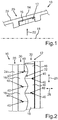
- Fig. 1 shows a detail of a sectional view of a protective device 10 for a turbomachine.
- the turbomachine is, for example, a gas turbine.
- the turbomachine may be part of an aircraft engine.
- the protective device 10 includes a retaining ring 12, which is arranged radially on the inside of a housing element 14 of the turbomachine and which at least predominantly prevents a penetration of the housing member 14 through a part of a component of the turbomachine in a structural failure of this component.
- This structural failure and prevention of penetration of the housing member 14 is also referred to as a containment case.
- Fig. 1 is the radial direction indicated by arrow 22, the axial direction of the turbomachine corresponds to its center line, which in Fig. 1 is provided with the reference numeral 18.
- a lid structure is further provided.
- This lid structure which in Fig. 1 is not shown for reasons of clarity, adjacent radially inwardly of the ring segments 16 and thus closes the space in which the ring segments are added.
- the lid structure may be a thin sheet metal component.
- it may be a so-called liner, which may have an abradable coating for the radially outer tips of blades. In the containment case, such a cover structure advantageously effects a certain distribution of the impact forces on the ring segments 16.
- the locking ring 12 is characterized in that it consists at least in the circumferential direction of a plurality of ring segments 16 which are positively connected with each other.
- the positive connection is formed in particular on the mutually facing end faces 40 of the ring segments 16.
- Fig. 1 is the circumferential direction substantially perpendicular to the image plane.
- the assembled from ring segments 16 retaining ring 12 receives its containment function by a positive connection with a circumferential latching.
- a game between the ring segments 16 is provided, which is just large enough that thermal expansions can be compensated by the retaining ring 12.
- This game is provided in particular in the circumferential direction between the end faces 40 of the ring segments 12 and is so small that under no circumstances creates a gaze gap.
- a different thermal expansion of the housing member 14 and the locking ring 12 can be compensated become. This is not readily possible with a similar but integral and continuous snap ring.
- the circlip 12 and the ring segments 16 are made of a ceramic material.
- a ceramic material can be particularly high-strength, temperature-resistant and heat-insulating. This makes it possible in particular to dispense with an additional thermal insulation, whereby the turbomachine can be particularly light. Especially the production of very large ceramic workpieces can be very expensive. Therefore, the locking ring 12, which consists of a plurality of ring segments 16, also particularly inexpensive to produce.
- the multipart retaining ring 12 can be mounted particularly easily even with undercut housing geometries. Individual ring segments 16 can be easily inserted or inserted. In particular, the ring segments 16 between an inlet lining for a Leitschaufehing and respective housing elements 14 can be inserted. This is not readily possible with a one-piece locking ring. A one-piece locking ring can be mounted at undercut housing geometries at all only with great effort.
- the retaining ring 12 By a circumferential latching and / or latching of the ring segments 16 with each other, it is possible to give the locking ring 12 as far as possible the properties of a closed ring. As a result, the retaining ring 12 thus constructed receives its full containment capability.
- the individual ring segments 16 can absorb tensile forces in the circumferential direction, as they can occur in a containment case.
- the circlip 12 coupled from ring segments 16 Upon impact of a fragment upon structural failure of a flow machine component, the circlip 12 coupled from ring segments 16 retains these fragments and prevents localized sharp penetration of fragment body edges into the housing member 14.
- the tensioning device 20 may for this purpose include, for example, a stator 24 with peripheral webs.
- the stator 24 abuts axially on the securing ring 12 and braces it axially against the housing element 14.
- the ring segments 16 are radially restrained in the tangential plane.
- the housing element 14 and / or other components are provided as elements of the clamping device 20.
- the tensioning device 20 axially clamps the ring segments 16. This creates a considerable wall friction. Due to the resulting force deflection and the tensile forces in the ring segments 16 are smaller than in an equivalent one-piece locking ring.
- the tensioning device 20 can contribute to the containability of the securing ring 12 by preventing or at least severely limiting an axial displacement of individual ring segments 16 in the containment case.
- the individual ring segments 16 of the securing ring 12 act by their positive connection similar to a closed ring, the locking ring 12 is under tension.
- two or possibly more rows of ring segments 16 may be arranged side by side in the axial direction and thereby be connected to each other by positive engagement so that the rows when the locking ring 12 device under tension, are pressed apart axially.
- the Fig. 2 to 4 show in a fragmentary radial plan view from the inside possible embodiments of the ring segments 16 and the locking ring 12.
- the radial direction corresponds to a direction perpendicular to the image plane of the Fig. 2 to 4
- the circumferential direction is in the Fig. 2 to 4 indicated by the arrow 26.
- the axial direction is marked accordingly by arrow 28.
- the retaining ring 12 comprises two rows 30 of ring segments 16, wherein a rotation of the two rows 30 to each other by a circumferential latching, toothing and / or offset of the respective ring segments 16 is prevented.
- the retaining ring 12 may be particularly inexpensive.
- the axial extent of the securing ring 12 can be varied so that larger ring segments 16 need not be manufactured.
- the self-inhibition of Rotation of the two rows 30 to each other thereby enhances the protective effect of the locking ring 12 so that it largely corresponds to that of a one-piece locking ring.
- Fig. 2 are the two rows 30 at their abutting each other in the circumferential direction side surfaces 32 by a wave-shaped course latched together and / or interlocked.
- the wave-shaped course of the side surfaces 32 ensures as uniform a force transmission as possible on these side surfaces 32. As a result, load peaks in the ring segments 16 and / or on their side surfaces 32 are avoided.
- This causes a particularly good self-locking.
- the retaining ring 12 is particularly easy to assemble, since the ring segments 16 are already fixed very well in their position during a partial assembly of the locking ring 12.
- an axial clearance similar to the game in the circumferential direction between the end faces 40 of the ring segments 12 may be provided.
- a different thermal expansion of the housing member 14, the retaining ring 12, the rows 30 and / or other elements of the turbomachine can be compensated, in particular in the axial direction.
- the protective device 10 is particularly advantageous to use in an aircraft engine. Especially in case of failure of the containment of an aircraft engine, it can lead to significant security risks. With the protection device 10, such a containment can be provided in a particularly cost-effective manner.
Landscapes
- Engineering & Computer Science (AREA)
- Mechanical Engineering (AREA)
- General Engineering & Computer Science (AREA)
- Chemical & Material Sciences (AREA)
- Combustion & Propulsion (AREA)
- Structures Of Non-Positive Displacement Pumps (AREA)
- Turbine Rotor Nozzle Sealing (AREA)
Applications Claiming Priority (1)
| Application Number | Priority Date | Filing Date | Title |
|---|---|---|---|
| DE102015204893.4A DE102015204893B3 (de) | 2015-03-18 | 2015-03-18 | Schutzeinrichtung für eine Strömungsmaschine |
Publications (2)
| Publication Number | Publication Date |
|---|---|
| EP3070278A2 true EP3070278A2 (fr) | 2016-09-21 |
| EP3070278A3 EP3070278A3 (fr) | 2016-11-02 |
Family
ID=55405221
Family Applications (1)
| Application Number | Title | Priority Date | Filing Date |
|---|---|---|---|
| EP16156672.4A Withdrawn EP3070278A3 (fr) | 2015-03-18 | 2016-02-22 | Dispositif de protection pour turbomachine |
Country Status (3)
| Country | Link |
|---|---|
| US (1) | US20160273380A1 (fr) |
| EP (1) | EP3070278A3 (fr) |
| DE (1) | DE102015204893B3 (fr) |
Cited By (1)
| Publication number | Priority date | Publication date | Assignee | Title |
|---|---|---|---|---|
| WO2019109197A1 (fr) * | 2017-12-04 | 2019-06-13 | 贵州智慧能源科技有限公司 | Carter de turbine |
Families Citing this family (5)
| Publication number | Priority date | Publication date | Assignee | Title |
|---|---|---|---|---|
| FR3081499B1 (fr) * | 2018-05-23 | 2021-05-28 | Safran Aircraft Engines | Secteur angulaire d'aubage de turbomachine a etancheite perfectionnee |
| US12372031B2 (en) * | 2023-05-18 | 2025-07-29 | Unison Industries, Llc | Air turbine starter with containment assembly |
| US12398661B2 (en) | 2024-01-29 | 2025-08-26 | Pratt & Whitney Canada Corp. | Containment ring for gas turbine engine |
| US12404780B2 (en) | 2024-01-29 | 2025-09-02 | Pratt & Whitney Canada Corp. | Containment ring for gas turbine engine |
| US12378894B1 (en) | 2024-01-29 | 2025-08-05 | Pratt & Whitney Canada Corp. | Containment ring for gas turbine engine |
Citations (4)
| Publication number | Priority date | Publication date | Assignee | Title |
|---|---|---|---|---|
| US5336044A (en) | 1993-08-06 | 1994-08-09 | General Electric Company | Blade containment system and method |
| DE69908540T2 (de) | 1998-12-23 | 2003-12-18 | United Technologies Corp., Hartford | Gasturbinentriebwerk |
| EP1918531A2 (fr) | 2006-11-06 | 2008-05-07 | Rolls-Royce Deutschland Ltd & Co KG | Anneau de rétention pour carter de soufflante dans un turboréacteur |
| EP2876262A1 (fr) | 2013-11-22 | 2015-05-27 | Rolls-Royce plc | Moteur à turbine à gaz |
Family Cites Families (7)
| Publication number | Priority date | Publication date | Assignee | Title |
|---|---|---|---|---|
| US3004700A (en) * | 1959-08-18 | 1961-10-17 | Gen Electric | Turbine engine casing |
| GB0116988D0 (en) * | 2000-08-11 | 2001-09-05 | Rolls Royce Plc | A gas turbine engine blade containment assembly |
| US6652222B1 (en) * | 2002-09-03 | 2003-11-25 | Pratt & Whitney Canada Corp. | Fan case design with metal foam between Kevlar |
| FR2913053B1 (fr) * | 2007-02-23 | 2009-05-22 | Snecma Sa | Procede de fabrication d'un carter de turbine a gaz en materiau composite et carter ainsi obtenu |
| GB2478144A (en) * | 2010-02-26 | 2011-08-31 | Rolls Royce Plc | Panelled assembly, eg for a gas turbine engine ducted fan casing |
| WO2013095210A1 (fr) * | 2011-12-22 | 2013-06-27 | Volvo Aero Corporation | Ensemble de confinement pour turbine à gaz |
| GB2524229B (en) * | 2014-02-14 | 2016-02-24 | Rolls Royce Plc | Gas turbine engine |
-
2015
- 2015-03-18 DE DE102015204893.4A patent/DE102015204893B3/de not_active Expired - Fee Related
-
2016
- 2016-02-22 EP EP16156672.4A patent/EP3070278A3/fr not_active Withdrawn
- 2016-03-17 US US15/073,550 patent/US20160273380A1/en not_active Abandoned
Patent Citations (4)
| Publication number | Priority date | Publication date | Assignee | Title |
|---|---|---|---|---|
| US5336044A (en) | 1993-08-06 | 1994-08-09 | General Electric Company | Blade containment system and method |
| DE69908540T2 (de) | 1998-12-23 | 2003-12-18 | United Technologies Corp., Hartford | Gasturbinentriebwerk |
| EP1918531A2 (fr) | 2006-11-06 | 2008-05-07 | Rolls-Royce Deutschland Ltd & Co KG | Anneau de rétention pour carter de soufflante dans un turboréacteur |
| EP2876262A1 (fr) | 2013-11-22 | 2015-05-27 | Rolls-Royce plc | Moteur à turbine à gaz |
Cited By (1)
| Publication number | Priority date | Publication date | Assignee | Title |
|---|---|---|---|---|
| WO2019109197A1 (fr) * | 2017-12-04 | 2019-06-13 | 贵州智慧能源科技有限公司 | Carter de turbine |
Also Published As
| Publication number | Publication date |
|---|---|
| US20160273380A1 (en) | 2016-09-22 |
| DE102015204893B3 (de) | 2016-06-09 |
| EP3070278A3 (fr) | 2016-11-02 |
Similar Documents
| Publication | Publication Date | Title |
|---|---|---|
| DE102015204893B3 (de) | Schutzeinrichtung für eine Strömungsmaschine | |
| EP2399004B1 (fr) | Section de rotor pour un rotor d'une turbomachine, aube rotorique pour une turbomachine et élément de blocage | |
| EP2191105A1 (fr) | Anneau de protection multicouche pour système de propulsion d'aéronef | |
| DE69918427T2 (de) | Rückhaltesystem für schaufelblattfragmente | |
| EP2344723B1 (fr) | Turbine à gaz avec plaques d'étanchéité sur le disque de turbine | |
| EP1944472A1 (fr) | Partie axiale d'un rotor de turbine, élément d'étanchéité pour un rotor équipé d'aubes de rotor d'une turbine et rotor de turbine | |
| EP2342425B1 (fr) | Turbine à gaz avec plaque de fixation entre la base d'aube et le disque | |
| EP3153667B1 (fr) | Dispositif de sécurisation axiale d'une aube mobile et dispositif de rotor équipé d'une telle sécurisation | |
| EP3054106B1 (fr) | Composant de turbine à gaz | |
| WO2012072384A1 (fr) | Turbomachine comportant une structure d'étanchéité entre des pièces tournantes et des pièces fixes ainsi que procédé de fabrication de ladite structure d'étanchéité | |
| EP1978211A1 (fr) | Dispositif de sécurité axiale sur des aubes mobiles d'un moteur tout comme turbine à gaz dotée d'un tel dispositif | |
| EP2173972B1 (fr) | Rotor pour turbomachine à flux axial | |
| DE102016104957A1 (de) | Kühleinrichtung zur Kühlung von Plattformen eines Leitschaufelkranzes einer Gasturbine | |
| EP2282014A1 (fr) | Section de canal d'écoulement annulaire pour une turbomachine | |
| EP2394028B1 (fr) | Dispositif d'étanchéité sur l'arbre à aubes d'un étage de rotor d'une turbomachine axiale et son utilisation | |
| EP1840338B1 (fr) | Arrangement pour la fermeture axiale des palettes d'une turbine dans un rotor et gasturbine avec un tel arrangement | |
| EP2333249B1 (fr) | Carter central d'un turbocompresseur | |
| EP3312388B1 (fr) | Pièce de rotor, compresseur, turbine et procédé de fabrication associés | |
| DE102010021220A1 (de) | Rotor sowie Turbomaschine | |
| EP2829687A1 (fr) | Confinement de boîtier et procédé de fabrication | |
| EP3260664A1 (fr) | Zone annulaire extérieure épaissie radialement d'une ailette d'étanchéité | |
| EP3153671A1 (fr) | Dispositif de protection pour turbomachine | |
| EP2194233B1 (fr) | Diviseur de flux pour un turboréacteur à double flux | |
| EP3921576B1 (fr) | Résonateur, procédé de fabrication d'un résonateur de ce type, et ensemble brûleur pourvu d'un résonateur de ce type | |
| EP2884052B1 (fr) | Rotor pour une turbomachine avec bague d'écoulement fermée profilée et son procédé de fabrication |
Legal Events
| Date | Code | Title | Description |
|---|---|---|---|
| PUAI | Public reference made under article 153(3) epc to a published international application that has entered the european phase |
Free format text: ORIGINAL CODE: 0009012 |
|
| AK | Designated contracting states |
Kind code of ref document: A2 Designated state(s): AL AT BE BG CH CY CZ DE DK EE ES FI FR GB GR HR HU IE IS IT LI LT LU LV MC MK MT NL NO PL PT RO RS SE SI SK SM TR |
|
| AX | Request for extension of the european patent |
Extension state: BA ME |
|
| PUAL | Search report despatched |
Free format text: ORIGINAL CODE: 0009013 |
|
| AK | Designated contracting states |
Kind code of ref document: A3 Designated state(s): AL AT BE BG CH CY CZ DE DK EE ES FI FR GB GR HR HU IE IS IT LI LT LU LV MC MK MT NL NO PL PT RO RS SE SI SK SM TR |
|
| AX | Request for extension of the european patent |
Extension state: BA ME |
|
| RIC1 | Information provided on ipc code assigned before grant |
Ipc: F01D 21/04 20060101ALI20160927BHEP Ipc: F02C 7/05 20060101ALI20160927BHEP Ipc: F01D 25/24 20060101AFI20160927BHEP |
|
| RBV | Designated contracting states (corrected) |
Designated state(s): AL AT BE BG CH CY CZ DE DK EE ES FI FR GB GR HR HU IE IS IT LI LT LU LV MC MK MT NL NO PL PT RO RS SE SI SK SM TR |
|
| 17P | Request for examination filed |
Effective date: 20170424 |
|
| RBV | Designated contracting states (corrected) |
Designated state(s): AL AT BE BG CH CY CZ DE DK EE ES FI FR GB GR HR HU IE IS IT LI LT LU LV MC MK MT NL NO PL PT RO RS SE SI SK SM TR |
|
| 17Q | First examination report despatched |
Effective date: 20180323 |
|
| GRAP | Despatch of communication of intention to grant a patent |
Free format text: ORIGINAL CODE: EPIDOSNIGR1 |
|
| INTG | Intention to grant announced |
Effective date: 20190704 |
|
| STAA | Information on the status of an ep patent application or granted ep patent |
Free format text: STATUS: THE APPLICATION IS DEEMED TO BE WITHDRAWN |
|
| 18D | Application deemed to be withdrawn |
Effective date: 20191115 |