EP3070360A2 - Embrayage unidirectionnel sélectionnable - Google Patents
Embrayage unidirectionnel sélectionnable Download PDFInfo
- Publication number
- EP3070360A2 EP3070360A2 EP16159370.2A EP16159370A EP3070360A2 EP 3070360 A2 EP3070360 A2 EP 3070360A2 EP 16159370 A EP16159370 A EP 16159370A EP 3070360 A2 EP3070360 A2 EP 3070360A2
- Authority
- EP
- European Patent Office
- Prior art keywords
- plate
- claw
- outer shell
- holding
- state
- Prior art date
- Legal status (The legal status is an assumption and is not a legal conclusion. Google has not performed a legal analysis and makes no representation as to the accuracy of the status listed.)
- Granted
Links
- 210000000078 claw Anatomy 0.000 claims abstract description 58
- 230000005540 biological transmission Effects 0.000 description 8
- 238000006073 displacement reaction Methods 0.000 description 6
- 238000004519 manufacturing process Methods 0.000 description 3
- 238000006243 chemical reaction Methods 0.000 description 2
- 230000002040 relaxant effect Effects 0.000 description 2
- 239000000470 constituent Substances 0.000 description 1
Images




Classifications
-
- F—MECHANICAL ENGINEERING; LIGHTING; HEATING; WEAPONS; BLASTING
- F16—ENGINEERING ELEMENTS AND UNITS; GENERAL MEASURES FOR PRODUCING AND MAINTAINING EFFECTIVE FUNCTIONING OF MACHINES OR INSTALLATIONS; THERMAL INSULATION IN GENERAL
- F16D—COUPLINGS FOR TRANSMITTING ROTATION; CLUTCHES; BRAKES
- F16D41/00—Freewheels or freewheel clutches
- F16D41/12—Freewheels or freewheel clutches with hinged pawl co-operating with teeth, cogs, or the like
- F16D41/125—Freewheels or freewheel clutches with hinged pawl co-operating with teeth, cogs, or the like the pawl movement having an axial component
-
- F—MECHANICAL ENGINEERING; LIGHTING; HEATING; WEAPONS; BLASTING
- F16—ENGINEERING ELEMENTS AND UNITS; GENERAL MEASURES FOR PRODUCING AND MAINTAINING EFFECTIVE FUNCTIONING OF MACHINES OR INSTALLATIONS; THERMAL INSULATION IN GENERAL
- F16D—COUPLINGS FOR TRANSMITTING ROTATION; CLUTCHES; BRAKES
- F16D41/00—Freewheels or freewheel clutches
- F16D41/12—Freewheels or freewheel clutches with hinged pawl co-operating with teeth, cogs, or the like
- F16D41/16—Freewheels or freewheel clutches with hinged pawl co-operating with teeth, cogs, or the like the action being reversible
-
- B—PERFORMING OPERATIONS; TRANSPORTING
- B60—VEHICLES IN GENERAL
- B60W—CONJOINT CONTROL OF VEHICLE SUB-UNITS OF DIFFERENT TYPE OR DIFFERENT FUNCTION; CONTROL SYSTEMS SPECIALLY ADAPTED FOR HYBRID VEHICLES; ROAD VEHICLE DRIVE CONTROL SYSTEMS FOR PURPOSES NOT RELATED TO THE CONTROL OF A PARTICULAR SUB-UNIT
- B60W30/00—Purposes of road vehicle drive control systems not related to the control of a particular sub-unit, e.g. of systems using conjoint control of vehicle sub-units
-
- F—MECHANICAL ENGINEERING; LIGHTING; HEATING; WEAPONS; BLASTING
- F16—ENGINEERING ELEMENTS AND UNITS; GENERAL MEASURES FOR PRODUCING AND MAINTAINING EFFECTIVE FUNCTIONING OF MACHINES OR INSTALLATIONS; THERMAL INSULATION IN GENERAL
- F16D—COUPLINGS FOR TRANSMITTING ROTATION; CLUTCHES; BRAKES
- F16D41/00—Freewheels or freewheel clutches
- F16D41/12—Freewheels or freewheel clutches with hinged pawl co-operating with teeth, cogs, or the like
- F16D41/14—Freewheels or freewheel clutches with hinged pawl co-operating with teeth, cogs, or the like the effective stroke of the pawl being adjustable
Definitions
- the disclosure relates to a selectable one-way clutch.
- JP 2002-514292 A describes a selectable one-way clutch.
- a plate including a claw provided in a projectable manner and a plate including a recessed portion with which the claw meshes are provided on the same axis By changing a state of the claw by a selector plate provided between two plates, a lock mode in which torque transmission between the two plates is allowed only at the time of a rotation in one predetermined direction, or a release mode in which torque transmission between the two plates is blocked only at the time of a rotation in both directions is selectable.
- the disclosure provides a selectable one-way clutch that can reduce displacement between axial centers at the time of joining two plates.
- An example aspect of the disclosure provides a selectable one-way clutch includes a first plate, a second plate, a claw, a selector plate and an outer shell.
- the second plate is placed on the same axis as the first plate, the second plate having a recessed portion.
- the claw is provided in the first plate.
- the claw is configured to project from the first plate toward the second plate.
- the claw is configured to mesh with the recessed portion of the second plate in a state where the claw projects from the first plate only at the time when the second plate rotates in a predetermined rotation direction.
- the selector plate is placed between the first plate and the second plate.
- the selector plate is configured to change a state of the claw between a state where the claw is projectable from the first plate and a state where the claw is maintained to be accommodated on a first-plate side.
- the outer shell is configured to cover an outer periphery of the first plate.
- the first plate is mounted on a holding member such that the first plate is non-rotatable around the axis and moves in a direction of the axis.
- the outer shell is configured to be immovable relative to the holding member in a state where the outer shell is positioned in a radial direction on the basis of the axis.
- the outer periphery of the first plate is covered with the outer shell and an inner periphery of the outer shell that covers the outer periphery of the first plate having a tapered shape in which a diameter is gradually reduced toward a direction distanced from the second plate.
- the claw provided in the first plate meshes with the recessed portion formed in the second plate so that the first plate is joined to the second plate, a force to distance the first plate and the second plate from each other with their axial centers being displaced is applied thereto.
- the inner periphery of the outer shell positioned in the radial direction on the basis of the axis and immovable relative to the holding member on which the first plate is mounted and the outer periphery of the first plate covered with the outer shell are formed in a tapered shape in which a diameter is gradually reduced toward a direction distanced from the second plate.
- the selectable one-way clutch may further include a biasing member.
- the biasing member may be provided between the first plate and the outer shell.
- the biasing member may be configured to bias the first plate and the outer shell in directions where the first plate and the outer shell are distanced from each other. According to the above aspect, when the first plate is released from the second plate, the first plate can be easily returned to an initial position distanced from the outer shell by the biasing member. Further, at the time when the first plate is joined to the second plate, the first plate moves in a direction distanced from the second plate so as to make contact with the outer shell. At this time, an impact caused due to the contact can be relaxed by the biasing member.
- the inner periphery of the outer shell positioned in the radial direction on the basis of the axis and immovable relative to the holding member on which the first plate is mounted and the outer periphery of the first plate covered with the outer shell are formed in a tapered shape in which a diameter is gradually reduced toward a direction distanced from the second plate.
- the inner periphery of the outer shell makes contact with the outer periphery of the first plate, so that the displacement of the axial center of the first plate can be reduced.
- a selectable one-way clutch (hereinafter referred to as a clutch) 1A illustrated in FIGS. 1 to 3 is used by being incorporated into a hybrid transformer axle (not shown).
- the clutch 1A is provided between a fixed shaft 101 fixed to a case 100 and a rotating shaft 102 rotatable around the same axis Ax as the fixed shaft 101.
- the clutch 1A can select an operation mode between a lock mode and a release mode.
- the lock mode is a mode in which a state where torque transmission from the rotating shaft 102 to the fixed shaft 101 is allowed so as to fix the rotating shaft 102 in a case where a rotation direction of the rotating shaft 102 is R1 and a state where the transmission torque is blocked so as to release the rotating shaft 102 in a case where the rotation direction is R2 are switched.
- the release mode is a mode in which torque transmission from the rotating shaft 102 to the fixed shaft 101 is blocked in either case where the rotation direction of the rotating shaft 102 is R1 or R2, so as to maintain the rotating shaft 102 is released.
- the clutch 1A includes: a holding plate 2 splined to the fixed shaft 101 in a state where the holding plate 2 is non-rotatable around the axis Ax but movable in an axis-Ax direction; a rotating plate 3 provided integrally rotatably around the axis Ax with the rotating shaft 102; a selector plate 4 placed between the holding plate 2 and the rotating plate 3 and provided rotatably around the axis Ax; and an outer shell 5 that covers an outer periphery of the holding plate 2.
- the outer shell 5 is fixed to the fixed shaft 101 in a state where the outer shell 5 is positioned in a radial direction based on the axis Ax, so the outer shell 5 is immovable relative to the fixed shaft 101 and the case 100.
- the holding plate 2 is one example of a first plate.
- the rotating plate 3 is one example of a second plate.
- the fixed shaft 101 on which the holding plate 2 is mounted is one example of a holding member.
- a plurality of holding chambers 10 is formed such that the plurality of holding chambers 10 is opened on a side opposed to the rotating plate 3 and arranged in a circumferential direction.
- Each of the holding chambers 10 is provided with one claw 11 meshing with the rotating plate 3.
- a base end 11a of each claw 11 is attached to the holding plate 2 via a spindle P rotatably around an axis Ax1 extending in a radial direction of the holding plate 2, and is biased by a spring 12 in a projection direction toward a rotating-plate-3 side.
- each claw 11 can be operated in a state where the each claw 11 is moved backward toward a holding-plate-2 side and accommodated in the holding chamber 10 or in a state where the each claw 11 projects from the holding plate 2 toward the rotating plate 3. That is, each claw 11 is provided in the holding plate 2 in a projectable state.
- a plurality of recessed portions 15 is formed such that the plurality of recessed portions 15 is opened on a side opposed to the holding plate 2 and arranged in a circumferential direction.
- Each of the recessed portions 15 includes a wall portion 15a with which a tip end 11b of the claw 11 abuts at the time when the projecting claw 11 meshes therewith.
- the number of recessed portions 15 is larger than the number of claws 11, and phases of the recessed portion 15 and phases of the claws 11 are shifted from each other (see FIG. 2 ). Accordingly, some of the plurality of projecting claws 11 mesh with some of the plurality of recessed portions 15.
- a plurality of through holes 16 which is arranged in the circumferential direction and through which the claws 11 projecting can be partially passed is formed with the same phases as the claws 11.
- a rotation position of the selector plate 4 can be switched between a locked position in FIG. 2 at which the claw 11 passes through the through hole 16 so that the claw 11 can mesh with the recessed portion 15 of the rotating plate 3, and a released position in FIG. 3 at which the tip end 11b of the claw 11 abuts with the selector plate 4 so as to limit projection of the claw 11 and maintain the claw 11 to be accommodated on the holding-plate-2 side.
- the lock mode and the release mode are performed selectively.
- the switching of the rotation position of the selector plate 4 is performed by an actuator (not shown).
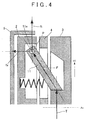
- a torque T is input into the claw 11 as illustrated in FIG. 4 .
- a force F is input into the spindle P placed in the base end 11a of the claw 11 due to the input of the torque T.
- the force F has a component force fx in the axis-Ax direction and a component force ft in a tangent direction of the holding plate 2.
- the holding plate 2 is splined to the fixed shaft 101 so as to be allowed to move in the axis-Ax direction. Accordingly, when the force F is input into the spindle P of the claw 11, the holding plate 2 and the rotating plate 3 are distanced from each other with their axial centers being displaced from each other.
- the clutch 1A is provided with the outer shell 5 for providing an alignment function to return the displaced axial center of the holding plate 2 to a normal place.
- the outer shell 5 is fixed to the fixed shaft 101, so as to cover the holding plate 2 except a facing side 2a that is opposed to the rotating plate 3.
- a predetermined clearance is secured between the outer shell 5 and the holding plate 2.
- An inner periphery 20 of the outer shell 5 is machined with accuracy, so that an inside diameter from the axis Ax to the inner periphery 20 is generally uniform around a whole circumference.
- the inner periphery 20 of the outer shell 5 and an outer periphery 21 of the holding plate 2 are formed in a tapered shape in which a diameter is gradually reduced toward a direction distanced from the rotating plate 3.
- the outer periphery 21 is covered with the inner periphery 20 of the outer shell 5.
- a taper angle ⁇ i of the inner periphery 20 and a taper angle ⁇ o of the outer periphery 21 are set to be equal to each other, but they may be different from each other.
- the inner periphery 20, the outer periphery 21, and a clearance C therebetween are set, so that, at the time when the holding plate 2 is moved in the axis-Ax direction, an opposite side 2b to the facing side 2a of the holding plate 2 does not make contact with an inner surface 5a of the outer shell 5.
- the inner surface 5a is opposed to the holding plate 2.
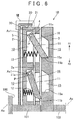
- a clutch 1B includes a return spring 30 as a biasing member provided between an inner surface 5a of an outer shell 5 and an opposite side 2b of a holding plate 2.
- the return spring 30 biases the holding plate 2 and the outer shell 5 in directions where they are distanced from each other. Note that, in FIGS. 6 and 7 , only one return spring 30 is illustrated. However, in consideration of a balance in a circumferential direction, a plurality of return springs 30 (e.g., six return springs 30) is provided at regular intervals in the circumferential direction of the holding plate 2.
- the holding plate 2 can be easily returned to an initial position (illustrated herein) distanced from the outer shell 5 by the return spring 30. Further, when the holding plate 2 moves in a direction distanced from the rotating plate 3 and makes contact with the outer shell 5 at the time when the holding plate 2 is joined to the rotating plate 3, an impact caused due to the contact can be relaxed by the return spring 30.
- each of the embodiments is just one application example of the clutch.
- the present invention can be carried out in an embodiment in which an outer shell is fixed, and a first plate and a second plate are rotatable relative to each other around the same axis.
- the present invention can be also carried out in an embodiment in which an outer shell and a first plate are integrally rotatable around the same axis and a second plate is rotatable relative to the first plate around the same axis.
- the outer shell 5 covers the holding plate 2 except the facing side 2a that is opposed to the rotating plate 3, but this is just an example.
- the outer shell may just cover the outer periphery of the first plate.
- the present invention can be carried out in an embodiment in which the outer periphery of the first plate is covered with a ring-shaped or tubular outer shell.
- the outer shell 5 is fixed to the fixed shaft 101, but an object to which the outer shell 5 is fixed may be the case 100 that stands still relative to the fixed shaft 101, for example.
- the outer shell may be in an immovable state relative to the holding member on which the first plate is mounted.
Landscapes
- Engineering & Computer Science (AREA)
- General Engineering & Computer Science (AREA)
- Mechanical Engineering (AREA)
- Automation & Control Theory (AREA)
- Transportation (AREA)
- Mechanical Operated Clutches (AREA)
Applications Claiming Priority (1)
| Application Number | Priority Date | Filing Date | Title |
|---|---|---|---|
| JP2015045911A JP6083447B2 (ja) | 2015-03-09 | 2015-03-09 | セレクタブルワンウエイクラッチ |
Publications (3)
| Publication Number | Publication Date |
|---|---|
| EP3070360A2 true EP3070360A2 (fr) | 2016-09-21 |
| EP3070360A3 EP3070360A3 (fr) | 2016-10-26 |
| EP3070360B1 EP3070360B1 (fr) | 2019-12-18 |
Family
ID=55524201
Family Applications (1)
| Application Number | Title | Priority Date | Filing Date |
|---|---|---|---|
| EP16159370.2A Active EP3070360B1 (fr) | 2015-03-09 | 2016-03-09 | Embrayage unidirectionnel sélectionnable |
Country Status (4)
| Country | Link |
|---|---|
| US (1) | US9657787B2 (fr) |
| EP (1) | EP3070360B1 (fr) |
| JP (1) | JP6083447B2 (fr) |
| CN (1) | CN105952813B (fr) |
Families Citing this family (4)
| Publication number | Priority date | Publication date | Assignee | Title |
|---|---|---|---|---|
| US9835206B2 (en) * | 2015-11-06 | 2017-12-05 | GM Global Technology Operations LLC | Selectable one-way clutch with torque independent release element |
| JP6665817B2 (ja) * | 2017-03-08 | 2020-03-13 | トヨタ自動車株式会社 | セレクタブルワンウェイクラッチ |
| JP6839070B2 (ja) * | 2017-12-18 | 2021-03-03 | 本田技研工業株式会社 | ツーウェイクラッチ状態検出装置、及びこの装置を用いた変速機及び車両 |
| DE102018130783A1 (de) * | 2018-12-04 | 2020-06-04 | Bayerische Motoren Werke Aktiengesellschaft | Freilauf für einen Kraftfahrzeugantriebsstrang |
Citations (1)
| Publication number | Priority date | Publication date | Assignee | Title |
|---|---|---|---|---|
| JP2002514292A (ja) | 1997-04-28 | 2002-05-14 | ミーンズ インダストリーズ インコーポレイテッド | 制御可能なオーバーランニング継手 |
Family Cites Families (6)
| Publication number | Priority date | Publication date | Assignee | Title |
|---|---|---|---|---|
| JP2002081469A (ja) * | 2000-09-07 | 2002-03-22 | Koyo Seiko Co Ltd | クラッチ装置 |
| JP2008082477A (ja) * | 2006-09-28 | 2008-04-10 | Mazda Motor Corp | 自動変速機 |
| US8602187B2 (en) * | 2009-03-13 | 2013-12-10 | Means Industries, Inc. | Overrunning one-way clutch or coupling assembly |
| US8506445B2 (en) * | 2010-01-27 | 2013-08-13 | GM Global Technology Operations LLC | Selectable torque transmitting device |
| US8449423B2 (en) * | 2010-11-10 | 2013-05-28 | GM Global Technology Operations LLC | Selectable one-way clutch with breakaway feature |
| US9249836B2 (en) * | 2013-08-15 | 2016-02-02 | Means Industries, Inc. | Coupling assembly having reduced undesirable noise and contact stress caused by a transition between operating modes of the assembly |
-
2015
- 2015-03-09 JP JP2015045911A patent/JP6083447B2/ja not_active Expired - Fee Related
-
2016
- 2016-03-08 CN CN201610130277.5A patent/CN105952813B/zh not_active Expired - Fee Related
- 2016-03-08 US US15/063,851 patent/US9657787B2/en not_active Expired - Fee Related
- 2016-03-09 EP EP16159370.2A patent/EP3070360B1/fr active Active
Patent Citations (1)
| Publication number | Priority date | Publication date | Assignee | Title |
|---|---|---|---|---|
| JP2002514292A (ja) | 1997-04-28 | 2002-05-14 | ミーンズ インダストリーズ インコーポレイテッド | 制御可能なオーバーランニング継手 |
Also Published As
| Publication number | Publication date |
|---|---|
| US9657787B2 (en) | 2017-05-23 |
| EP3070360A3 (fr) | 2016-10-26 |
| CN105952813B (zh) | 2018-12-04 |
| JP2016166632A (ja) | 2016-09-15 |
| US20160265604A1 (en) | 2016-09-15 |
| CN105952813A (zh) | 2016-09-21 |
| EP3070360B1 (fr) | 2019-12-18 |
| JP6083447B2 (ja) | 2017-02-22 |
Similar Documents
| Publication | Publication Date | Title |
|---|---|---|
| CN102562863B (zh) | 用于可选择的单向离合器组件的三模式选择机构 | |
| EP2839177B1 (fr) | Ensemble d'accouplement et de commande | |
| EP2183499B1 (fr) | Embrayage a roue libre | |
| EP3070360B1 (fr) | Embrayage unidirectionnel sélectionnable | |
| JP6661316B2 (ja) | 一方向クラッチ | |
| CN107614917A (zh) | 具有间隙布置的电子控制可选择的离合器 | |
| US9746039B2 (en) | Wedge friction clutch with onboard enable and disable function | |
| JP6577441B2 (ja) | ドグクラッチ | |
| EP4194711A1 (fr) | Dispositif de transmission de puissance | |
| CN108571536B (zh) | 湿式多片离合器 | |
| CN104100659B (zh) | 具有带有卡口式连接部的压力环的离合器 | |
| KR20100118642A (ko) | 더블클러치 | |
| JP6426026B2 (ja) | 流体継手 | |
| JP7416643B2 (ja) | 多板クラッチ装置 | |
| US8079454B2 (en) | Friction engagement apparatus | |
| KR20170090415A (ko) | 유체 조인트 | |
| EP3869050B1 (fr) | Agencement pour dispositif de frein de commutation | |
| JP7845930B2 (ja) | クラッチ装置 | |
| JP7860836B2 (ja) | クラッチ装置 | |
| KR102270679B1 (ko) | 원웨이 클러치 및 이를 구비하는 토크 컨버터 | |
| JP4987337B2 (ja) | クラッチユニット | |
| JP7126850B2 (ja) | トルクコンバータ用のスラストワッシャ | |
| JP2024162350A (ja) | クラッチ装置 | |
| JP2017082822A (ja) | ドグクラッチ | |
| JP6285796B2 (ja) | ロックアップ装置 |
Legal Events
| Date | Code | Title | Description |
|---|---|---|---|
| PUAI | Public reference made under article 153(3) epc to a published international application that has entered the european phase |
Free format text: ORIGINAL CODE: 0009012 |
|
| 17P | Request for examination filed |
Effective date: 20160309 |
|
| AK | Designated contracting states |
Kind code of ref document: A2 Designated state(s): AL AT BE BG CH CY CZ DE DK EE ES FI FR GB GR HR HU IE IS IT LI LT LU LV MC MK MT NL NO PL PT RO RS SE SI SK SM TR |
|
| AX | Request for extension of the european patent |
Extension state: BA ME |
|
| PUAL | Search report despatched |
Free format text: ORIGINAL CODE: 0009013 |
|
| AK | Designated contracting states |
Kind code of ref document: A3 Designated state(s): AL AT BE BG CH CY CZ DE DK EE ES FI FR GB GR HR HU IE IS IT LI LT LU LV MC MK MT NL NO PL PT RO RS SE SI SK SM TR |
|
| AX | Request for extension of the european patent |
Extension state: BA ME |
|
| RIC1 | Information provided on ipc code assigned before grant |
Ipc: F16D 41/12 20060101AFI20160922BHEP |
|
| GRAP | Despatch of communication of intention to grant a patent |
Free format text: ORIGINAL CODE: EPIDOSNIGR1 |
|
| STAA | Information on the status of an ep patent application or granted ep patent |
Free format text: STATUS: GRANT OF PATENT IS INTENDED |
|
| INTG | Intention to grant announced |
Effective date: 20190718 |
|
| GRAS | Grant fee paid |
Free format text: ORIGINAL CODE: EPIDOSNIGR3 |
|
| GRAA | (expected) grant |
Free format text: ORIGINAL CODE: 0009210 |
|
| STAA | Information on the status of an ep patent application or granted ep patent |
Free format text: STATUS: THE PATENT HAS BEEN GRANTED |
|
| AK | Designated contracting states |
Kind code of ref document: B1 Designated state(s): AL AT BE BG CH CY CZ DE DK EE ES FI FR GB GR HR HU IE IS IT LI LT LU LV MC MK MT NL NO PL PT RO RS SE SI SK SM TR |
|
| REG | Reference to a national code |
Ref country code: CH Ref legal event code: EP |
|
| REG | Reference to a national code |
Ref country code: IE Ref legal event code: FG4D |
|
| REG | Reference to a national code |
Ref country code: DE Ref legal event code: R096 Ref document number: 602016026228 Country of ref document: DE |
|
| REG | Reference to a national code |
Ref country code: AT Ref legal event code: REF Ref document number: 1214935 Country of ref document: AT Kind code of ref document: T Effective date: 20200115 |
|
| REG | Reference to a national code |
Ref country code: NL Ref legal event code: MP Effective date: 20191218 |
|
| PG25 | Lapsed in a contracting state [announced via postgrant information from national office to epo] |
Ref country code: NO Free format text: LAPSE BECAUSE OF FAILURE TO SUBMIT A TRANSLATION OF THE DESCRIPTION OR TO PAY THE FEE WITHIN THE PRESCRIBED TIME-LIMIT Effective date: 20200318 Ref country code: LV Free format text: LAPSE BECAUSE OF FAILURE TO SUBMIT A TRANSLATION OF THE DESCRIPTION OR TO PAY THE FEE WITHIN THE PRESCRIBED TIME-LIMIT Effective date: 20191218 Ref country code: SE Free format text: LAPSE BECAUSE OF FAILURE TO SUBMIT A TRANSLATION OF THE DESCRIPTION OR TO PAY THE FEE WITHIN THE PRESCRIBED TIME-LIMIT Effective date: 20191218 Ref country code: FI Free format text: LAPSE BECAUSE OF FAILURE TO SUBMIT A TRANSLATION OF THE DESCRIPTION OR TO PAY THE FEE WITHIN THE PRESCRIBED TIME-LIMIT Effective date: 20191218 Ref country code: BG Free format text: LAPSE BECAUSE OF FAILURE TO SUBMIT A TRANSLATION OF THE DESCRIPTION OR TO PAY THE FEE WITHIN THE PRESCRIBED TIME-LIMIT Effective date: 20200318 Ref country code: LT Free format text: LAPSE BECAUSE OF FAILURE TO SUBMIT A TRANSLATION OF THE DESCRIPTION OR TO PAY THE FEE WITHIN THE PRESCRIBED TIME-LIMIT Effective date: 20191218 Ref country code: GR Free format text: LAPSE BECAUSE OF FAILURE TO SUBMIT A TRANSLATION OF THE DESCRIPTION OR TO PAY THE FEE WITHIN THE PRESCRIBED TIME-LIMIT Effective date: 20200319 |
|
| REG | Reference to a national code |
Ref country code: LT Ref legal event code: MG4D |
|
| PG25 | Lapsed in a contracting state [announced via postgrant information from national office to epo] |
Ref country code: RS Free format text: LAPSE BECAUSE OF FAILURE TO SUBMIT A TRANSLATION OF THE DESCRIPTION OR TO PAY THE FEE WITHIN THE PRESCRIBED TIME-LIMIT Effective date: 20191218 Ref country code: HR Free format text: LAPSE BECAUSE OF FAILURE TO SUBMIT A TRANSLATION OF THE DESCRIPTION OR TO PAY THE FEE WITHIN THE PRESCRIBED TIME-LIMIT Effective date: 20191218 |
|
| PG25 | Lapsed in a contracting state [announced via postgrant information from national office to epo] |
Ref country code: AL Free format text: LAPSE BECAUSE OF FAILURE TO SUBMIT A TRANSLATION OF THE DESCRIPTION OR TO PAY THE FEE WITHIN THE PRESCRIBED TIME-LIMIT Effective date: 20191218 |
|
| PG25 | Lapsed in a contracting state [announced via postgrant information from national office to epo] |
Ref country code: EE Free format text: LAPSE BECAUSE OF FAILURE TO SUBMIT A TRANSLATION OF THE DESCRIPTION OR TO PAY THE FEE WITHIN THE PRESCRIBED TIME-LIMIT Effective date: 20191218 Ref country code: NL Free format text: LAPSE BECAUSE OF FAILURE TO SUBMIT A TRANSLATION OF THE DESCRIPTION OR TO PAY THE FEE WITHIN THE PRESCRIBED TIME-LIMIT Effective date: 20191218 Ref country code: PT Free format text: LAPSE BECAUSE OF FAILURE TO SUBMIT A TRANSLATION OF THE DESCRIPTION OR TO PAY THE FEE WITHIN THE PRESCRIBED TIME-LIMIT Effective date: 20200513 Ref country code: RO Free format text: LAPSE BECAUSE OF FAILURE TO SUBMIT A TRANSLATION OF THE DESCRIPTION OR TO PAY THE FEE WITHIN THE PRESCRIBED TIME-LIMIT Effective date: 20191218 Ref country code: CZ Free format text: LAPSE BECAUSE OF FAILURE TO SUBMIT A TRANSLATION OF THE DESCRIPTION OR TO PAY THE FEE WITHIN THE PRESCRIBED TIME-LIMIT Effective date: 20191218 |
|
| PG25 | Lapsed in a contracting state [announced via postgrant information from national office to epo] |
Ref country code: SM Free format text: LAPSE BECAUSE OF FAILURE TO SUBMIT A TRANSLATION OF THE DESCRIPTION OR TO PAY THE FEE WITHIN THE PRESCRIBED TIME-LIMIT Effective date: 20191218 Ref country code: IS Free format text: LAPSE BECAUSE OF FAILURE TO SUBMIT A TRANSLATION OF THE DESCRIPTION OR TO PAY THE FEE WITHIN THE PRESCRIBED TIME-LIMIT Effective date: 20200418 Ref country code: SK Free format text: LAPSE BECAUSE OF FAILURE TO SUBMIT A TRANSLATION OF THE DESCRIPTION OR TO PAY THE FEE WITHIN THE PRESCRIBED TIME-LIMIT Effective date: 20191218 |
|
| REG | Reference to a national code |
Ref country code: DE Ref legal event code: R097 Ref document number: 602016026228 Country of ref document: DE |
|
| REG | Reference to a national code |
Ref country code: AT Ref legal event code: MK05 Ref document number: 1214935 Country of ref document: AT Kind code of ref document: T Effective date: 20191218 |
|
| PLBE | No opposition filed within time limit |
Free format text: ORIGINAL CODE: 0009261 |
|
| STAA | Information on the status of an ep patent application or granted ep patent |
Free format text: STATUS: NO OPPOSITION FILED WITHIN TIME LIMIT |
|
| PG25 | Lapsed in a contracting state [announced via postgrant information from national office to epo] |
Ref country code: DK Free format text: LAPSE BECAUSE OF FAILURE TO SUBMIT A TRANSLATION OF THE DESCRIPTION OR TO PAY THE FEE WITHIN THE PRESCRIBED TIME-LIMIT Effective date: 20191218 Ref country code: ES Free format text: LAPSE BECAUSE OF FAILURE TO SUBMIT A TRANSLATION OF THE DESCRIPTION OR TO PAY THE FEE WITHIN THE PRESCRIBED TIME-LIMIT Effective date: 20191218 Ref country code: MC Free format text: LAPSE BECAUSE OF FAILURE TO SUBMIT A TRANSLATION OF THE DESCRIPTION OR TO PAY THE FEE WITHIN THE PRESCRIBED TIME-LIMIT Effective date: 20191218 |
|
| REG | Reference to a national code |
Ref country code: CH Ref legal event code: PL |
|
| 26N | No opposition filed |
Effective date: 20200921 |
|
| PG25 | Lapsed in a contracting state [announced via postgrant information from national office to epo] |
Ref country code: AT Free format text: LAPSE BECAUSE OF FAILURE TO SUBMIT A TRANSLATION OF THE DESCRIPTION OR TO PAY THE FEE WITHIN THE PRESCRIBED TIME-LIMIT Effective date: 20191218 Ref country code: SI Free format text: LAPSE BECAUSE OF FAILURE TO SUBMIT A TRANSLATION OF THE DESCRIPTION OR TO PAY THE FEE WITHIN THE PRESCRIBED TIME-LIMIT Effective date: 20191218 |
|
| REG | Reference to a national code |
Ref country code: BE Ref legal event code: MM Effective date: 20200331 |
|
| PG25 | Lapsed in a contracting state [announced via postgrant information from national office to epo] |
Ref country code: LU Free format text: LAPSE BECAUSE OF NON-PAYMENT OF DUE FEES Effective date: 20200309 |
|
| PG25 | Lapsed in a contracting state [announced via postgrant information from national office to epo] |
Ref country code: IT Free format text: LAPSE BECAUSE OF FAILURE TO SUBMIT A TRANSLATION OF THE DESCRIPTION OR TO PAY THE FEE WITHIN THE PRESCRIBED TIME-LIMIT Effective date: 20191218 Ref country code: CH Free format text: LAPSE BECAUSE OF NON-PAYMENT OF DUE FEES Effective date: 20200331 Ref country code: LI Free format text: LAPSE BECAUSE OF NON-PAYMENT OF DUE FEES Effective date: 20200331 Ref country code: IE Free format text: LAPSE BECAUSE OF NON-PAYMENT OF DUE FEES Effective date: 20200309 |
|
| PG25 | Lapsed in a contracting state [announced via postgrant information from national office to epo] |
Ref country code: BE Free format text: LAPSE BECAUSE OF NON-PAYMENT OF DUE FEES Effective date: 20200331 Ref country code: PL Free format text: LAPSE BECAUSE OF FAILURE TO SUBMIT A TRANSLATION OF THE DESCRIPTION OR TO PAY THE FEE WITHIN THE PRESCRIBED TIME-LIMIT Effective date: 20191218 |
|
| PGFP | Annual fee paid to national office [announced via postgrant information from national office to epo] |
Ref country code: GB Payment date: 20220127 Year of fee payment: 7 Ref country code: DE Payment date: 20220203 Year of fee payment: 7 |
|
| PG25 | Lapsed in a contracting state [announced via postgrant information from national office to epo] |
Ref country code: TR Free format text: LAPSE BECAUSE OF FAILURE TO SUBMIT A TRANSLATION OF THE DESCRIPTION OR TO PAY THE FEE WITHIN THE PRESCRIBED TIME-LIMIT Effective date: 20191218 Ref country code: MT Free format text: LAPSE BECAUSE OF FAILURE TO SUBMIT A TRANSLATION OF THE DESCRIPTION OR TO PAY THE FEE WITHIN THE PRESCRIBED TIME-LIMIT Effective date: 20191218 Ref country code: CY Free format text: LAPSE BECAUSE OF FAILURE TO SUBMIT A TRANSLATION OF THE DESCRIPTION OR TO PAY THE FEE WITHIN THE PRESCRIBED TIME-LIMIT Effective date: 20191218 |
|
| PGFP | Annual fee paid to national office [announced via postgrant information from national office to epo] |
Ref country code: FR Payment date: 20220209 Year of fee payment: 7 |
|
| PG25 | Lapsed in a contracting state [announced via postgrant information from national office to epo] |
Ref country code: MK Free format text: LAPSE BECAUSE OF FAILURE TO SUBMIT A TRANSLATION OF THE DESCRIPTION OR TO PAY THE FEE WITHIN THE PRESCRIBED TIME-LIMIT Effective date: 20191218 |
|
| P01 | Opt-out of the competence of the unified patent court (upc) registered |
Effective date: 20230427 |
|
| REG | Reference to a national code |
Ref country code: DE Ref legal event code: R119 Ref document number: 602016026228 Country of ref document: DE |
|
| GBPC | Gb: european patent ceased through non-payment of renewal fee |
Effective date: 20230309 |
|
| PG25 | Lapsed in a contracting state [announced via postgrant information from national office to epo] |
Ref country code: GB Free format text: LAPSE BECAUSE OF NON-PAYMENT OF DUE FEES Effective date: 20230309 |
|
| PG25 | Lapsed in a contracting state [announced via postgrant information from national office to epo] |
Ref country code: GB Free format text: LAPSE BECAUSE OF NON-PAYMENT OF DUE FEES Effective date: 20230309 Ref country code: FR Free format text: LAPSE BECAUSE OF NON-PAYMENT OF DUE FEES Effective date: 20230331 Ref country code: DE Free format text: LAPSE BECAUSE OF NON-PAYMENT OF DUE FEES Effective date: 20231003 |