EP3070403A1 - Dispositif d'alimentation des particules de combustible solid pour une chambre de combustion - Google Patents
Dispositif d'alimentation des particules de combustible solid pour une chambre de combustion Download PDFInfo
- Publication number
- EP3070403A1 EP3070403A1 EP16160008.5A EP16160008A EP3070403A1 EP 3070403 A1 EP3070403 A1 EP 3070403A1 EP 16160008 A EP16160008 A EP 16160008A EP 3070403 A1 EP3070403 A1 EP 3070403A1
- Authority
- EP
- European Patent Office
- Prior art keywords
- supply device
- combustion
- combustion chamber
- fuel
- fluid
- Prior art date
- Legal status (The legal status is an assumption and is not a legal conclusion. Google has not performed a legal analysis and makes no representation as to the accuracy of the status listed.)
- Withdrawn
Links
- 238000002485 combustion reaction Methods 0.000 title claims abstract description 198
- 239000002245 particle Substances 0.000 title claims abstract description 110
- 239000004449 solid propellant Substances 0.000 title claims description 11
- 239000012530 fluid Substances 0.000 claims abstract description 125
- 239000000446 fuel Substances 0.000 claims abstract description 123
- 239000007787 solid Substances 0.000 claims abstract description 14
- 238000005259 measurement Methods 0.000 claims abstract description 9
- 238000000034 method Methods 0.000 claims description 22
- 241000196324 Embryophyta Species 0.000 claims description 20
- 239000000203 mixture Substances 0.000 claims description 20
- 239000000567 combustion gas Substances 0.000 claims description 12
- QVGXLLKOCUKJST-UHFFFAOYSA-N atomic oxygen Chemical compound [O] QVGXLLKOCUKJST-UHFFFAOYSA-N 0.000 claims description 8
- 239000001301 oxygen Substances 0.000 claims description 8
- 229910052760 oxygen Inorganic materials 0.000 claims description 8
- VNWKTOKETHGBQD-UHFFFAOYSA-N methane Chemical compound C VNWKTOKETHGBQD-UHFFFAOYSA-N 0.000 claims description 6
- 238000006073 displacement reaction Methods 0.000 claims description 5
- 239000002023 wood Substances 0.000 claims description 5
- LFQSCWFLJHTTHZ-UHFFFAOYSA-N Ethanol Chemical compound CCO LFQSCWFLJHTTHZ-UHFFFAOYSA-N 0.000 claims description 4
- 239000003546 flue gas Substances 0.000 claims description 4
- XLYOFNOQVPJJNP-UHFFFAOYSA-N water Substances O XLYOFNOQVPJJNP-UHFFFAOYSA-N 0.000 claims description 4
- UGFAIRIUMAVXCW-UHFFFAOYSA-N Carbon monoxide Chemical compound [O+]#[C-] UGFAIRIUMAVXCW-UHFFFAOYSA-N 0.000 claims description 3
- 239000003345 natural gas Substances 0.000 claims description 3
- 239000003921 oil Substances 0.000 claims description 3
- 239000004033 plastic Substances 0.000 claims description 3
- 229920003023 plastic Polymers 0.000 claims description 3
- 230000001737 promoting effect Effects 0.000 claims description 3
- 239000010801 sewage sludge Substances 0.000 claims description 3
- 240000007817 Olea europaea Species 0.000 claims description 2
- 239000002154 agricultural waste Substances 0.000 claims description 2
- 239000003245 coal Substances 0.000 claims description 2
- 239000011261 inert gas Substances 0.000 claims description 2
- 229920005610 lignin Polymers 0.000 claims description 2
- 239000011368 organic material Substances 0.000 claims description 2
- 239000003415 peat Substances 0.000 claims description 2
- 239000002826 coolant Substances 0.000 description 20
- 239000007789 gas Substances 0.000 description 11
- 230000001276 controlling effect Effects 0.000 description 6
- 238000004140 cleaning Methods 0.000 description 4
- 239000002803 fossil fuel Substances 0.000 description 4
- 239000007788 liquid Substances 0.000 description 4
- 238000001816 cooling Methods 0.000 description 3
- 231100001261 hazardous Toxicity 0.000 description 3
- IJGRMHOSHXDMSA-UHFFFAOYSA-N Atomic nitrogen Chemical compound N#N IJGRMHOSHXDMSA-UHFFFAOYSA-N 0.000 description 2
- CURLTUGMZLYLDI-UHFFFAOYSA-N Carbon dioxide Chemical compound O=C=O CURLTUGMZLYLDI-UHFFFAOYSA-N 0.000 description 2
- 230000006835 compression Effects 0.000 description 2
- 238000007906 compression Methods 0.000 description 2
- 238000013461 design Methods 0.000 description 2
- 239000010791 domestic waste Substances 0.000 description 2
- 238000002156 mixing Methods 0.000 description 2
- 239000008188 pellet Substances 0.000 description 2
- 239000000843 powder Substances 0.000 description 2
- 238000000197 pyrolysis Methods 0.000 description 2
- 229910000831 Steel Inorganic materials 0.000 description 1
- 238000007664 blowing Methods 0.000 description 1
- 229910002092 carbon dioxide Inorganic materials 0.000 description 1
- 239000001569 carbon dioxide Substances 0.000 description 1
- 230000001419 dependent effect Effects 0.000 description 1
- 238000001514 detection method Methods 0.000 description 1
- 238000010586 diagram Methods 0.000 description 1
- 230000000694 effects Effects 0.000 description 1
- 230000007613 environmental effect Effects 0.000 description 1
- 238000002309 gasification Methods 0.000 description 1
- 238000002347 injection Methods 0.000 description 1
- 239000007924 injection Substances 0.000 description 1
- 238000003780 insertion Methods 0.000 description 1
- 230000037431 insertion Effects 0.000 description 1
- 239000003350 kerosene Substances 0.000 description 1
- 238000012423 maintenance Methods 0.000 description 1
- -1 natural gas Chemical compound 0.000 description 1
- 229910052757 nitrogen Inorganic materials 0.000 description 1
- 230000000737 periodic effect Effects 0.000 description 1
- 230000001105 regulatory effect Effects 0.000 description 1
- 239000004071 soot Substances 0.000 description 1
- 239000007921 spray Substances 0.000 description 1
- 239000010959 steel Substances 0.000 description 1
- 239000000126 substance Substances 0.000 description 1
- 230000032258 transport Effects 0.000 description 1
- 238000011144 upstream manufacturing Methods 0.000 description 1
- 238000009834 vaporization Methods 0.000 description 1
Images
Classifications
-
- F—MECHANICAL ENGINEERING; LIGHTING; HEATING; WEAPONS; BLASTING
- F23—COMBUSTION APPARATUS; COMBUSTION PROCESSES
- F23D—BURNERS
- F23D1/00—Burners for combustion of pulverulent fuel
-
- F—MECHANICAL ENGINEERING; LIGHTING; HEATING; WEAPONS; BLASTING
- F23—COMBUSTION APPARATUS; COMBUSTION PROCESSES
- F23C—METHODS OR APPARATUS FOR COMBUSTION USING FLUID FUEL OR SOLID FUEL SUSPENDED IN A CARRIER GAS OR AIR
- F23C5/00—Disposition of burners with respect to the combustion chamber or to one another; Mounting of burners in combustion apparatus
- F23C5/02—Structural details of mounting
- F23C5/06—Provision for adjustment of burner position during operation
-
- F—MECHANICAL ENGINEERING; LIGHTING; HEATING; WEAPONS; BLASTING
- F23—COMBUSTION APPARATUS; COMBUSTION PROCESSES
- F23K—FEEDING FUEL TO COMBUSTION APPARATUS
- F23K3/00—Feeding or distributing of lump or pulverulent fuel to combustion apparatus
- F23K3/02—Pneumatic feeding arrangements, i.e. by air blast
-
- F—MECHANICAL ENGINEERING; LIGHTING; HEATING; WEAPONS; BLASTING
- F23—COMBUSTION APPARATUS; COMBUSTION PROCESSES
- F23L—SUPPLYING AIR OR NON-COMBUSTIBLE LIQUIDS OR GASES TO COMBUSTION APPARATUS IN GENERAL ; VALVES OR DAMPERS SPECIALLY ADAPTED FOR CONTROLLING AIR SUPPLY OR DRAUGHT IN COMBUSTION APPARATUS; INDUCING DRAUGHT IN COMBUSTION APPARATUS; TOPS FOR CHIMNEYS OR VENTILATING SHAFTS; TERMINALS FOR FLUES
- F23L7/00—Supplying non-combustible liquids or gases, other than air, to the fire, e.g. oxygen, steam
- F23L7/002—Supplying water
- F23L7/005—Evaporated water; Steam
-
- F—MECHANICAL ENGINEERING; LIGHTING; HEATING; WEAPONS; BLASTING
- F23—COMBUSTION APPARATUS; COMBUSTION PROCESSES
- F23N—REGULATING OR CONTROLLING COMBUSTION
- F23N5/00—Systems for controlling combustion
- F23N5/003—Systems for controlling combustion using detectors sensitive to combustion gas properties
-
- F—MECHANICAL ENGINEERING; LIGHTING; HEATING; WEAPONS; BLASTING
- F23—COMBUSTION APPARATUS; COMBUSTION PROCESSES
- F23N—REGULATING OR CONTROLLING COMBUSTION
- F23N5/00—Systems for controlling combustion
- F23N5/02—Systems for controlling combustion using devices responsive to thermal changes or to thermal expansion of a medium
-
- F—MECHANICAL ENGINEERING; LIGHTING; HEATING; WEAPONS; BLASTING
- F23—COMBUSTION APPARATUS; COMBUSTION PROCESSES
- F23C—METHODS OR APPARATUS FOR COMBUSTION USING FLUID FUEL OR SOLID FUEL SUSPENDED IN A CARRIER GAS OR AIR
- F23C2900/00—Special features of, or arrangements for combustion apparatus using fluid fuels or solid fuels suspended in air; Combustion processes therefor
- F23C2900/07021—Details of lances
-
- F—MECHANICAL ENGINEERING; LIGHTING; HEATING; WEAPONS; BLASTING
- F23—COMBUSTION APPARATUS; COMBUSTION PROCESSES
- F23D—BURNERS
- F23D2201/00—Burners adapted for particulate solid or pulverulent fuels
- F23D2201/20—Fuel flow guiding devices
-
- F—MECHANICAL ENGINEERING; LIGHTING; HEATING; WEAPONS; BLASTING
- F23—COMBUSTION APPARATUS; COMBUSTION PROCESSES
- F23D—BURNERS
- F23D2208/00—Control devices associated with burners
-
- F—MECHANICAL ENGINEERING; LIGHTING; HEATING; WEAPONS; BLASTING
- F23—COMBUSTION APPARATUS; COMBUSTION PROCESSES
- F23D—BURNERS
- F23D2214/00—Cooling
-
- F—MECHANICAL ENGINEERING; LIGHTING; HEATING; WEAPONS; BLASTING
- F23—COMBUSTION APPARATUS; COMBUSTION PROCESSES
- F23G—CREMATION FURNACES; CONSUMING WASTE PRODUCTS BY COMBUSTION
- F23G2209/00—Specific waste
- F23G2209/12—Sludge, slurries or mixtures of liquids
-
- F—MECHANICAL ENGINEERING; LIGHTING; HEATING; WEAPONS; BLASTING
- F23—COMBUSTION APPARATUS; COMBUSTION PROCESSES
- F23G—CREMATION FURNACES; CONSUMING WASTE PRODUCTS BY COMBUSTION
- F23G2209/00—Specific waste
- F23G2209/26—Biowaste
- F23G2209/261—Woodwaste
-
- F—MECHANICAL ENGINEERING; LIGHTING; HEATING; WEAPONS; BLASTING
- F23—COMBUSTION APPARATUS; COMBUSTION PROCESSES
- F23K—FEEDING FUEL TO COMBUSTION APPARATUS
- F23K2203/00—Feeding arrangements
- F23K2203/008—Feeding devices for pulverulent fuel
-
- F—MECHANICAL ENGINEERING; LIGHTING; HEATING; WEAPONS; BLASTING
- F23—COMBUSTION APPARATUS; COMBUSTION PROCESSES
- F23N—REGULATING OR CONTROLLING COMBUSTION
- F23N5/00—Systems for controlling combustion
- F23N5/16—Systems for controlling combustion using noise-sensitive detectors
- F23N2005/165—Systems for controlling combustion using noise-sensitive detectors with ultrasonic means
Definitions
- the invention relates to a method and a supply device for supplying a secondary fuel to a combustion chamber.
- heat generating plants such as boilers, incinerator furnaces and technically corresponding apparatuses are designed to combust or burn different kinds of fuels.
- different kinds of hazardous gases and/or particles may be formed or released.
- the amount of these hazardous gases and/or particles depends, among other things, on how well or completely the fuel is being combusted or burnt. This in turn depends on e.g. the temperature of the grate and the combustion chamber, the amount of available air and other substances that are present to be used by the combustion process and so on.
- different kinds of supply devices for supplying fluid to an internal combustion chamber of a heat generating plant have been devised.
- Supply devices may also be used providing a secondary fuel to the combustion chamber, thereby improving the efficiency of the furnace. It is a general problem within the field that old heat generating plants are often designed for fossil fuel combustion, which is less and less desirable in view of environmental effects. Many plants are thus converted for using a renewable or less harmful fuel source such as wood pellets, household waste etc. However, such fuels often have a lover energy content why a larger amount of fuel may need to be combusted in order for the plant to operate efficiently. However, the combustion chambers are not so easily modified and it may be very expensive to demolish and rebuild large combustion chambers to allow for a higher fuel supply.
- a supply device for supplying a particulate secondary fuel carried by a carrier fluid to a combustion chamber is known from WO 2014/058381 .
- Said devices also simplify de-sooting and cleaning of the tubes included in the device, a feature which also enhances the yield of the combustion and vaporisation process respectively.
- the devices also enable different fluids or solids to be supplied at different points of time, through one or more of said tubes, so that a new optimal operating point can be set in relation to the prevailing operating state of the combustion chamber.
- a particular advantage afforded by the known supply devices is that one or more tubes can be withdrawn while still enabling the combustion or gasification process to continue with the use of the remaining tubes.
- a supply device must be able to operate reliably over a long period of time in a demanding environment.
- the tube that is inserted into the combustion chamber, according to prior art, is subjected to high stresses as a result of the high temperature and the corrosive environment that prevail.
- the optimal place for injecting fluid or solid particles into the combustion gases of the chamber by means of a supply device may vary over time.
- This has been solved by using a plurality of tubes and/or a plurality of injection holes in each tube.
- tubes positioned close to the grate may be subjected to a too harsh and corrosive environment.
- a tubular supply device for supplying solid fuel particles as a secondary fuel and a combustion adjusting fluid into a combustion chamber in a heat generating plant.
- the supply device has a first end, a second end and a longitudinal axis.
- the supply device comprises an outer tube forming an outer lateral surface of the supply device.
- the supply device also comprises an inner tube positioned inside the outer tube such that an axial space is formed surrounding the inner tube between said inner tube and the outer tube.
- the supply device also comprises coolant connectors at the second end of the supply device and configured for being inlet and outlet, respectively, of a cooling medium allowed to circulate in the axial space of the supply device between the inner tube and the outer tube.
- the supply device also comprises a connector located at the second end of the supply device configured for connecting a supply-line for supply of the fuel particles into the inner tube.
- the supply device also comprises at least one opening through the outer tube and the inner tube at the first end of the supply device.
- the supply device also comprises a supply pipe for supplying the combustion adjusting fluid to the fuel particles such that the combustion adjusting fluid is mixed with the fuel particles carried by a carrier fluid whereby a mixture of the fuel particles and the combustion adjusting fluid can be injected into the combustion chamber through the opening by means of the carrier fluid.
- a supply device assembly for supplying solid particles and a combustion adjusting fluid to a combustion chamber in a heat generating plant.
- the combustion chamber is delimited by at least one wall.
- the assembly comprises an embodiment of the tubular supply device of the present disclosure.
- the supply device extends, led by its first end, into the combustion chamber through a through hole in the wall of the combustion chamber.
- the assembly also comprises a displacing device in mesh with the supply device for axial displacement of the tubular device through the hole in the chamber wall.
- the assembly also comprises a supply line connected to the connector for supply of the fuel particles, the supply line providing a flow channel between the inner tube and a supply source of the fuel particles.
- a method of supplying solid fuel particles as a secondary fuel and a combustion adjusting fluid to a combustion chamber in a heat generating plant said combustion chamber being delimited at least one wall.
- the method comprises providing a tubular supply device extending, led by a first end of said supply device, into the combustion chamber through a through hole in the wall of the combustion chamber.
- the method also comprises circulating a cooling medium in an axial space formed between an inner tube and an outer tube forming an outer lateral surface of the supply device.
- the method also comprises supplying a flow of the fuel particles from a supply source into the inner tube at a second end of the supply device.
- the method also comprises supplying a flow of a carrier fluid into the inner tube at the second end of the supply device such that the fuel particles are carried by the carrier fluid in the inner tube from the second end of the supply device towards the first end of the supply device along a longitudinal axis of said supply device.
- the method also comprises supplying a flow of a combustion adjusting fluid to the fuel particles from a supply pipe, such that the combustion adjusting fluid forms a mixture with the fuel particles carried by the carrier fluid.
- the method also comprises injecting the mixture of the fuel particles and the combustion adjusting fluid into the combustion chamber through the opening by means of the carrier fluid.
- the combustion adjusting fluid which is mixed with the secondary fuel, it is possible to control where in the combustion chamber the secondary fuel is combusted. Specifically, the distance from the supply device at which the fuel is combusted after having been injected into the chamber may be controlled.
- the combustion adjusting fluid may e.g. delay the combustion of the secondary fuel, allowing it to combust further away from the supply device.
- Examples of such combustion delaying fluids are e.g. water or an aqueous mixture, or an inert gas e.g. nitrogen, carbon dioxide or flue gas, which inhibits the combustion of the secondary fuel. It may be advantageous to delay the combustion e.g. if the optimal combustion zone for the secondary fuel is, possibly temporarily, further away from the supply device e.g.
- the combustion adjusting fluid may be a combustion promoting fluid which promotes the combustion of the secondary fuel, which may be desirable if e.g. the secondary fuel is difficult to ignite for instance has a large particle size or contains moisture, or if the optimal combustion zone is higher up/further away from the grate in the combustion chamber.
- combustion promoting fluids are flammable liquids or gases e.g. liquids such as and alcohol or oil, or gases such as natural gas, biogas or pyrolysis gas, or oxygen or an oxygen rich gas.
- the supply device assembly may further comprise a control unit configured for controlling the amount and/or type of combustion adjusting fluid mixed with the fuel particles based on sensor measurements from within the combustion chamber.
- tube or “tubular” is intended to denote a hollow substantially cylindrical, e.g. substantially circular cylindrical, structure being delimited by a lateral surface and first and second end surfaces.
- the lateral surface is substantially parallel to the central longitudinal axis of the tube, whereas the respective end surfaces are substantially not parallel to the central longitudinal axis of the tube but intersects the central longitudinal axis of the tube.
- the tube has a first end with the first end surface, and a second end with the second end surface. Conveniently, the first and second ends do not include any of the lateral surface.
- the first end When the tube is inserted into the combustion chamber, the first end may be regarded as an inner end since it extends, is inserted, into the combustion chamber, whereas the second end may be regarded as an outer end since it extends through an outer wall of the combustion chamber, such that the second end is in or outside said outer wall.
- the apertures/openings discussed herein are thus apertures through one of these surfaces.
- the second end surface i.e. the surface of the second end of the tube, may, depending on the design of the tube, more or less substantially consist of an aperture.
- the tube may be a substantially circular tube, i.e. have a substantially circular cross-section perpendicular to the central longitudinal axis, but other shapes are also contemplated, such as a square or rectangular tube.
- That something is at the first or second end of the supply device, such as the opening thorough the tubes being at the first end of the supply device or the displacing device meshing with or engaging the supply device at its second end, implies that it is on/in the end surface or on/in the lateral surface but in close proximity of, or adjacent to, the end surface and at least closer to that (first or second) end surface than to the other (first or second) end surface of the supply device.
- the tubular supply device may be of any size, but it may be convenient to use an outer tube which has a longitudinal length of less than 10m, such as less than 5m, in order to reduce the lateral stress on the tube, especially if the supply device is inserted substantially horizontally into the combustion chamber.
- the diameter of the outer tube may also be of any size, but it may be convenient to use a tube with a diameter of less than 250 mm, such as less than 200 mm, less than 150 mm, less than 120 mm or less than 100 mm, in order to reduce the weight of the supply device to make it more easy to handle and move, axially and/or rotationally around its longitudinal axis.
- Another advantage with using a smaller supply device is that less cooling may be needed of the tube, since the tube takes up heat in relation to its outer surface area.
- Only one supply device may be used in a combustion chamber, but it may also be convenient to use a plurality of supply devices, e.g. substantially parallel to each other, at different positions in the combustion chamber.
- the supply devices may then co-operate with each other to provide optimal supply of the fluid and solid particles in the combustion chamber, e.g. improved mixture of the fluid and solid particles with the atmosphere in the combustion chamber and/or improved coverage of the combustion chamber volume by being able to supply the fluid and solid particles at more different positions in the combustion chamber.
- the supply device may be inserted into the combustion chamber in any direction. It may be convenient to insert the supply device vertically, e.g. hanging through the top wall (ceiling/roof) of the combustion chamber in order to reduce the lateral stresses on the supply device and the mounting of the supply device in the chamber wall, and/or on the displacing device. On the other hand it may be convenient to insert the supply device horizontally, e.g. through a side wall of the combustion chamber. Depending on the design on the combustion chamber, it may be easier to reach the place within the combustion chamber where it is desired to supply the fluid and solid particles in the combustion chamber with a horizontal supply device. A vertically inserted supply device may need to be much longer and thus heavier in order to reach the same position in the combustion chamber as a substantially smaller horizontally inserted supply device.
- the supply device may be provided with means for supplying a cooling agent to said supply device for cooling of said supply device. This has the advantage that the tube can operate for longer periods of time in a very hot environment.
- the displacing device or means for displacing said supply device may be arranged so as to permit rotation of the supply device around its longitudinal axis.
- the supply device may further be associated with a cleaning means, e.g. mechanically by means of steel pins or brushes, or pneumatically by means of blowing air or steam for cleaning the outer tube during its axial inward and/or outward movement in the combustion chamber.
- a cleaning means e.g. mechanically by means of steel pins or brushes, or pneumatically by means of blowing air or steam for cleaning the outer tube during its axial inward and/or outward movement in the combustion chamber.
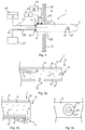
- FIG. 1 is a schematic illustration of an embodiment of a supply device 1 of the present invention, when the supply device is inserted into a combustion chamber 4 through a hole 23 in a wall 24 of the combustion chamber.
- the supply device 1 has a first end 5 extending into the combustion chamber 4 and a second end 6 extending out of said chamber 4.
- the supply device 1 has a longitudinal axis 7 which is herein used for reference when discussing the present invention.
- the wall 24 may e.g. be a vertical or a horizontal wall of the combustion chamber 4.
- Coolant connectors 10 at the second end 6 of the device 1 provides an inlet and an outlet of cooling medium circulating in the supply device.
- a coolant supply pipe 25 guides cooling medium, e.g.
- a coolant recirculation pipe 26 guides the heated coolant from the supply device, e.g. back to the coolant source 27 to be cooled, possibly partly by heat exchanging with the carrier fluid 3 before said fluid enters the supply device.
- a connector 11 for connecting a supply-line 12 for supply of the solid particles 2 into the supply device from a particle supply source 28 is also positioned at the second end 6 of the device 1.
- the particles may be transported through the supply line 12 by and in mixture with the carrier fluid 3, or the carrier fluid 3 from a carrier fluid source 32 may be enter the supply device 1 via a separate connector 34 whereby the particles 2 may be mixed with the carrier fluid 3 inside the supply device.
- the supply line 12 may also extend inside the supply device 1, substantially in parallel with the axis 7, for transporting the particles 2, e.g. carried by the carrier fluid 3, along the supply device at least partly to the opening 13.
- the opening 13 through a later surface of the outer tube 8 of the tubular supply device allows the particles 2 carried by the carrier fluid 3 to exit the supply device and be emitted into the chamber 4, e.g. at least partly counter currently with the combustion gases in the combustion chamber.
- Any number of opening(s) 13 may be provided in the supply device 1, in its lateral surface and/or its first end surface, but in figure 1 only one opening is shown for simplifying the figure.
- a supply pipe 17 carries the combustion adjusting fluid 30 from the source 31 and into the supply device 1.
- the supply pipe 17 also carries the combustion adjusting fluid 30 within and along the supply device 1 substantially in parallel with the axis 7.
- the outlet of the supply pipe 17 is schematically shown through the opening 13, where the combustion adjusting fluid exits the supply pipe and mixes with the fuel particles 2.
- Figure 2a and 2b are schematic illustrations in longitudinal section of the first end 5 of embodiments of the supply device 1.
- An outer tube 8 forms an outer lateral surface of the supply device and an inner tube 9 is, typically substantially concentrically, positioned inside the outer tube such that an axial space 14 is formed surrounding the inner tube 9 between said inner tube and the outer tube 8.
- the axial space 14 is configured for allowing a cooling medium to flow there through.
- figure 2a there are for example two openings 13, one in the lateral surface of the supply device 1 and one in the first end surface of the supply device, while the embodiment of figure 2b has as an example only one, lateral, opening 13 at the first end 5 of the supply device.
- the particulate fuel 2 is transported within the inner tube 9, possibly in a pipe (not shown), carried by the carrier fluid and is blown into the chamber 4 through the one or more opening(s) 13 as indicated with the thick arrows in the opening(s) 13 in the figures.
- the supply pipe 17 emits, e.g. sprays, the combustion adjusting fluid 30 within the inner tube 9 such that the combustion adjusting fluid mixes with the particulate fuel 2 inside the inner tube.
- the mixture of particulate fuel and combustion adjusting fluid 30, carried by the carrier fluid 3, is then injected into chamber 4 through the openings 13.
- the supply pipe 17 may be arranged for supplying the combustion adjusting fluid 30 to the fuel particles 2 within the inner tube 9 while the fuel particles are carried through the inner tube by the carrier fluid 3.
- the supply pipe 17 transports the combustion adjusting fluid 30 substantially all the way to the opening(s) 13, but preferably not extending outside of the outer tube 8 to avoid extending parts of the supply device 1 which may cause problems when longitudinally displacing it.
- the combustion adjusting fluid 30 is emitted, e.g. sprayed, from the supply pipe 17 to mix with the particulate fuel as it is blown into the chamber 4.
- the supply pipe 17 may be arranged for supplying the combustion adjusting fluid 30 to the fuel particles 2 at the opening 13 when the fuel particles are injected into the combustion chamber 4 such that the mixing at least partly takes place outside of the outer tube 8.
- Figure 2c illustrates another embodiment.
- a part of the tubular supply device 1 is shown, not in section, with an opening 13 through a lateral surface of the outer tube 8.
- the combustion adjusting fluid 30 is emitted, e.g. sprayed from a plurality of nozzles, from the outlet of the supply pipe 17 around the outlet of the supply line/pipe 12 carrying the flow of particulate fuel 2 and carrier fluid 3.
- This embodiment may provide improved mixing of the combustion adjusting fluid with the particulate fuel, and since the combustion adjusting fluid 30 is injected into the chamber 4 between the particulate fuel 2 and the flue gases in the chamber 4, the particulate fuel is somewhat protected from the environment in the chamber by the combustion adjusting fluid even before the fuel is fully mixed with the combustion adjusting fluid in the chamber.
- the opening 13 is through a lateral surface of the inner and outer tubes 8 and 9.
- the flow can e.g. be directed downwards, towards the hearth/grate from a horizontally positioned supply device 1 in a combustion chamber 4.
- the opening is in the end surface of the first end 5of the device 1, e.g. allowing the particles 2 to be more easily injected forwards along the longitudinal axis 7 whereby the supply device may extend a shorter length into the combustion chamber, allowing the device to be made smaller and reducing the gravitational strain on a horizontally extending tubular supply device.
- the angle may be towards a direction against the flow direction of the gas in the combustion chamber, typically downward for a horizontally mounted supply device.
- the supply device 1 is mounted through a through hole 23 in a wall 24 of the combustion chamber 4, e.g. a vertical wall if the device is inserted horizontally into the chamber, or a horizontal wall or ceiling if the device is inserted vertically into the chamber e.g. hanging from the ceiling.
- a displacing device is in mesh with the supply device for axial displacement of the tubular device 1 through the hole 23 in the chamber wall. By axial displacement, the position in the chamber to which the particles 2 are injected/emitted (the terms injected and emitted are herein used interchangeably) may be controlled, and the tubular device may be removed to the outside of the chamber 4 for maintenance etc.
- the supply device may be axially displaced out from the combustion chamber when it is not in use, i.e. when it is not supplying solid fuel particles 2 into the combustion chamber 4.
- the displacing device may be arranged for rotation of the tubular supply device 1, further increasing the control of to where in the chamber 4 the particles are injected.
- the supply device 1 is associated with a particle analysing device arranged for measuring a particle size of the solid fuel particles 2 in a flow channel between the supply source 28 and the opening/outlet 13.
- the particle size may e.g. be a number average particle size or a weight average particle size.
- the size of the particles may be relevant for to where in the chamber they should be injected, which may be controlled by different controlling parameters e.g. by the amount of combustion adjusting fluid 30 added, the speed/pressure of the carrier fluid 3 and/or the position (axial displacement and/or rotation) of the supply device 1 in the chamber.
- a particulate fuel 2 having a large particle size may travel further from the supply device before combusting than a fuel having a smaller particle size.
- Associating the particle analysing device may e.g. allow any of the controlling parameters to be adjusted in view of continuous or periodic analysis of the particle size. This is relevant e.g. since the particle size can vary over time. For instance, larger particles have a tendency to move to the top of a supply source.
- the supply device 1 is associated with a control unit configured for controlling the angle between the direction of outlet flow of the particles 2 and the longitudinal axis 7 depending on the particle size measured by the particle analysing device.
- the supply device is associated with a carrier fluid compression unit configured to adjust the pressure of the carrier fluid 3 depending on the particle size measured by the particle analysing device.
- a flame detector is mounted on, or otherwise associated with, the supply device 1 inside the combustion chamber 4.
- the flame detector may e.g. be connected to the control unit and/or compression unit for regulating the particle emission in view of flame detection.
- a flame detector is an example of a sensor which may be used for estimating the optimal combustion zone of the secondary fuel 2, but other sensors such as temperature, acoustic and/or ultrasonic sensors may also or alternatively be used.
- a control unit of the supply device assembly may be configured for controlling the amount of combustion adjusting fluid 30 mixed with the fuel particles 2 based on sensor measurements from within the combustion chamber 4.
- the sensor measurements may e.g. be any of temperature, flame, acoustic and/or ultrasonic measurements.
- the heated cooling medium exiting the supply device 1 is used to pre-heat the carrier fluid 3 before it enters the supply device, e.g. by means of a liquid-gas heat exchanger if the cooling medium is a liquid and the carrier fluid is a gas.
- a liquid-gas heat exchanger if the cooling medium is a liquid and the carrier fluid is a gas.
- the fuel particles 2 are a secondary fuel. It is convenient to use the supply device 1 of the present invention for adding a secondary fuel, complementing a primary fuel added at the bottom grate of the chamber 4.
- the particles 2 may be supplied counter current to the combustion gases from the upstream main combustion zone.
- the supply 1 device may be used when additional (secondary) fuel is useful for obtaining extra power/effect from the furnace, e.g. less than 50% additional power/fuel energy input such as between 5 and 30% or between 10 and 20% energy input may be added by means of the supply device.
- the present invention may be used for upgrading a heat generating plant which is designed for fossil fuel combustion.
- the grate and combustion chamber may not be designed for the lower energy density of such a fuel, why the heat generating plant may not operate optimally.
- the combustion chamber 4 may easily be upgraded by making a through hole 23 in one of its walls 24 for insertion of the supply device 1 of the present invention for supplying a particulate secondary fuel 2 to the combustion chamber for combustion in the combustion gases from the primary fuel. This is a much simpler and cheaper upgrade than a more extensive upgrade for allowing more primary fuel to be combusted.
- the solid particles 2 may e.g. be of a medium calorific fuel such as a non-fossil fuel e.g.
- the particulate solid fuel 2 may be of an organic material, e.g. any of wood, peat, plastics, dried sewage sludge, coal, lignin, dried agricultural waste, olive kernels, or of a mixture thereof.
- a primary fuel is combusted at the bottom of the combustion chamber 4 and the solid particles 2 are a secondary fuel emitted into combustion gases of the combustion chamber from the combustion of the primary fuel.
- the solid particles are emitted in a direction which is at least partly counter current to the combustion gases. This may improve the combustion of the fuel particles.
- At least 100 kg/h, e.g. at least 500 kg/h or at least 1000 kg/h, of solid particles 2 are emitted from the supply device 1. This implies that a large amount of secondary fuel can be injected into the combustion chamber.
- the carrier fluid 3 preferably has pressure/speed sufficient to inject the particles 2 with a speed which is higher than the speed of the combustion gases. Otherwise, the particles risk being swept away by the combustion gases.
- the combustion gases may typically have a speed of 3-10m/s, why the speed of the carrier fluid 3 and the fuel particles 2 as they are injected into the combustion chamber 4 preferably is at least 5 m/s, e.g. between 5 and 15 m/s.
- the carrier fluid is air, recirculated flue gas, oxygen enriched air, oxygen, or a mixture thereof. If the carrier fluid comprises oxygen, the present device may additionally be designed to provide secondary oxygen to the combustion chamber for improved combustion.
- a tubular supply device 1 for supplying solid fuel particles 2 as a secondary fuel and a combustion adjusting fluid 30 to a combustion chamber 4 in a heat generating plant, said supply device having a first end 5, a second end 6 and a longitudinal axis 7, and comprising: a tube 8 and/or 9; an opening 13 through the tube at the first end; and a supply pipe 17 for supplying the combustion adjusting fluid 30 to the fuel particles 2 such that the combustion adjusting fluid is mixed with the fuel particles whereby a mixture of the fuel particles and the combustion adjusting fluid 30 can be injected into the combustion chamber 4 through the opening 13.
- a tubular supply device 1 for supplying a secondary fuel 2 and a combustion adjusting fluid 30 to a combustion chamber 4 in a heat generating plant, said supply device having a first end 5, a second end 6 and a longitudinal axis 7, and comprising: a tube 8 and/or 9; an opening 13 through the tube at the first end; and a supply pipe 17 for supplying the combustion adjusting fluid 30 to the fuel 2 such that the combustion adjusting fluid is mixed with the fuel whereby a mixture of the fuel and the combustion adjusting fluid 30 can be injected into the combustion chamber 4 through the opening 13.
- a tubular supply device 1 for supplying a secondary fuel 2 and a combustion adjusting fluid 30 to a combustion chamber 4 in a heat generating plant, said supply device having a first end 5, a second end 6 and a longitudinal axis 7, and comprising: an outer tube 8 forming an outer lateral surface of the supply device; an inner tube 9 positioned inside the outer tube such that an axial space 14 is formed surrounding the inner tube 9 between said inner tube and the outer tube 8; coolant connectors 10 at the second end 6 of the supply device and configured for being inlet and outlet, respectively, of a cooling medium allowed to circulate in the axial space 14 of the supply device between the inner tube 9 and the outer tube 8; a connector 11 located at the second end 6 of the supply device configured for connecting a supply line 12 for supply of the fuel 2 into the inner tube 9; at least one opening 13 through the outer tube 8 and the inner tube 9 at the first end 5 of the supply device 1; and a supply pipe 17 for supplying the combustion adjusting fluid to
- a tubular supply device 1 for supplying solid fuel particles 2 as a secondary fuel and a combustion adjusting fluid 30 to a combustion chamber 4 in a heat generating plant, said supply device having a first end 5, a second end 6 and a longitudinal axis 7.
- the supply device comprises: an outer tube 8 forming an outer lateral surface of the supply device; an inner tube 9 positioned inside the outer tube such that an axial space 14 is formed surrounding the inner tube 9 between said inner tube and the outer tube 8; coolant connectors 10 at the second end 6 of the supply device and configured for being inlet and outlet, respectively, of a cooling medium allowed to circulate in the axial space 14 of the supply device between the inner tube 9 and the outer tube 8; a connector 11 located at the second end 6 of the supply device configured for connecting a supply-line 12 for supply of the fuel particles 2 into the inner tube 9; at least one opening 13 through the outer tube 8 and the inner tube 9 at the first end 5 of the supply device 1; and a supply pipe 17 for supplying the combustion adjusting fluid to the fuel particles 2 such that the combustion adjusting fluid is mixed with the fuel particles carried by a carrier fluid 3 whereby a mixture of the fuel particles and the combustion adjusting fluid 30 can be injected into the combustion chamber 4 through the opening 13 by means of the carrier fluid.
- the supply pipe 17 is
- the method comprises providing a tubular supply device 1 extending, led by a first end 5 of said supply device, into the combustion chamber 4 through a through hole 23 in the wall of the combustion chamber; optionally circulating a cooling medium in an axial space formed between an inner tube 9 and an outer tube 8 forming an outer lateral surface of the supply device 1; supplying a flow of the fuel particles 2 from a supply source 28 into the tubular supply device 1, e.g.
Landscapes
- Engineering & Computer Science (AREA)
- Chemical & Material Sciences (AREA)
- Combustion & Propulsion (AREA)
- Mechanical Engineering (AREA)
- General Engineering & Computer Science (AREA)
Applications Claiming Priority (1)
| Application Number | Priority Date | Filing Date | Title |
|---|---|---|---|
| SE1550315A SE1550315A1 (en) | 2015-03-16 | 2015-03-16 | Supply device for a combustion chamber |
Publications (1)
| Publication Number | Publication Date |
|---|---|
| EP3070403A1 true EP3070403A1 (fr) | 2016-09-21 |
Family
ID=55527442
Family Applications (1)
| Application Number | Title | Priority Date | Filing Date |
|---|---|---|---|
| EP16160008.5A Withdrawn EP3070403A1 (fr) | 2015-03-16 | 2016-03-11 | Dispositif d'alimentation des particules de combustible solid pour une chambre de combustion |
Country Status (2)
| Country | Link |
|---|---|
| EP (1) | EP3070403A1 (fr) |
| SE (1) | SE1550315A1 (fr) |
Citations (7)
| Publication number | Priority date | Publication date | Assignee | Title |
|---|---|---|---|---|
| DE306765C (fr) | ||||
| US5112216A (en) | 1988-12-22 | 1992-05-12 | Chemetics International Company Inc. | Pulp mill gas combustion process |
| SE502188C2 (sv) | 1992-06-05 | 1995-09-11 | Ulf Hagstroem | Sätt och anordning för att undvika störningar orsakade av beläggningar på tillförseldon till förbrännings- eller förgasningsanläggning |
| SE502283C2 (sv) | 1993-12-03 | 1995-09-25 | Ulf Hagstroem | Sätt och tillförseldon för att reglera blandningsförhållanden i en förbrännings- eller förgasningsanläggning |
| EP1530005A2 (fr) * | 2003-11-10 | 2005-05-11 | Babcock-Hitachi Kabushiki Kaisha | Brûleur et appareil de combustion pour combustible solide, méthode de combustion associée |
| EP2221537A1 (fr) * | 2007-09-25 | 2010-08-25 | Babcock-Hitachi Kabushiki Kaisha | Brûleur à combustible solide, dispositif de combustion utilisant un brûleur à combustible solide et procédé de fonctionnement du dispositif de combustion |
| WO2014058381A1 (fr) | 2012-10-11 | 2014-04-17 | Ecomb Ab (Publ) | Dispositif d'alimentation pour une chambre de combustion |
-
2015
- 2015-03-16 SE SE1550315A patent/SE1550315A1/en not_active Application Discontinuation
-
2016
- 2016-03-11 EP EP16160008.5A patent/EP3070403A1/fr not_active Withdrawn
Patent Citations (7)
| Publication number | Priority date | Publication date | Assignee | Title |
|---|---|---|---|---|
| DE306765C (fr) | ||||
| US5112216A (en) | 1988-12-22 | 1992-05-12 | Chemetics International Company Inc. | Pulp mill gas combustion process |
| SE502188C2 (sv) | 1992-06-05 | 1995-09-11 | Ulf Hagstroem | Sätt och anordning för att undvika störningar orsakade av beläggningar på tillförseldon till förbrännings- eller förgasningsanläggning |
| SE502283C2 (sv) | 1993-12-03 | 1995-09-25 | Ulf Hagstroem | Sätt och tillförseldon för att reglera blandningsförhållanden i en förbrännings- eller förgasningsanläggning |
| EP1530005A2 (fr) * | 2003-11-10 | 2005-05-11 | Babcock-Hitachi Kabushiki Kaisha | Brûleur et appareil de combustion pour combustible solide, méthode de combustion associée |
| EP2221537A1 (fr) * | 2007-09-25 | 2010-08-25 | Babcock-Hitachi Kabushiki Kaisha | Brûleur à combustible solide, dispositif de combustion utilisant un brûleur à combustible solide et procédé de fonctionnement du dispositif de combustion |
| WO2014058381A1 (fr) | 2012-10-11 | 2014-04-17 | Ecomb Ab (Publ) | Dispositif d'alimentation pour une chambre de combustion |
Also Published As
| Publication number | Publication date |
|---|---|
| SE1550315A1 (en) | 2016-09-17 |
Similar Documents
| Publication | Publication Date | Title |
|---|---|---|
| CA3152394A1 (fr) | Installation de chauffage a biomasse comportant un traitement optimise des gaz de combustion | |
| CN104769384A (zh) | 用于改装燃烧器前部并将第二燃料注入通用炉中的系统和方法 | |
| EP2537912A1 (fr) | Appareil et procédé pour la décomposition thermochimique à cycle continu d'une biomasse | |
| EP2588809B1 (fr) | Procédé et système pour l'incinération, à faible émission, de gaz résiduels faiblement calorifiques | |
| KR101781373B1 (ko) | 연소실 구분연소에 따른 소각효율이 향상된 유동층 소각로 설비 | |
| KR101029046B1 (ko) | 가스버너 및 그 가스버너를 사용한 바이오매스 연료 처리장치 | |
| JP7811841B2 (ja) | アンモニア燃料ボイラシステム | |
| CA2816293C (fr) | Bruleur a air secondaire unidirectionnel | |
| JP5498434B2 (ja) | バイオマス燃焼ボイラ | |
| US20150292737A1 (en) | Supply device for a combustion chamber | |
| EP2863123B1 (fr) | Procédé pour incinérer des gaz pauvres contenant des composants azotés, comme par exemple NH3, HCN, C5H5N, dans les chambres de combustion d'une installation énergétique industrielle, et système pour mettre en oeuvre le procédé | |
| EP3734158B1 (fr) | Méthode de réduction d'oxydes d'azote et de monoxyde de carbone dans les chambres de combustion des chaudières à eau et à vapeur, en particulier des chaudières à grille. | |
| JP6466157B2 (ja) | 重質油焚きボイラの燃焼方法及び重質油焚きボイラ | |
| KR101385851B1 (ko) | 유동층 보일러 및 이를 이용한 연소 제어방법 | |
| Bohn et al. | Flame temperatures and species concentrations in non-stoichiometric oxycoal flames | |
| RU2309332C1 (ru) | Многофункциональная горелка | |
| SE1550315A1 (en) | Supply device for a combustion chamber | |
| KR101854568B1 (ko) | 고체 연료 연소 시스템 | |
| KR101267877B1 (ko) | 저열량가스와 유류 혼소장치 | |
| KR100978349B1 (ko) | 보일러 | |
| CN204593370U (zh) | 一种煤粉炉的烟气再循环系统 | |
| CN220229123U (zh) | 一种生物质低氮燃烧机 | |
| Gaba et al. | Recovery of waste gas by combustion in an originally designed plant | |
| CN102032591A (zh) | 一种煤粉点火系统及其控制方法 | |
| EA020592B1 (ru) | Печь для сжигания твердого топлива |
Legal Events
| Date | Code | Title | Description |
|---|---|---|---|
| PUAI | Public reference made under article 153(3) epc to a published international application that has entered the european phase |
Free format text: ORIGINAL CODE: 0009012 |
|
| AK | Designated contracting states |
Kind code of ref document: A1 Designated state(s): AL AT BE BG CH CY CZ DE DK EE ES FI FR GB GR HR HU IE IS IT LI LT LU LV MC MK MT NL NO PL PT RO RS SE SI SK SM TR |
|
| AX | Request for extension of the european patent |
Extension state: BA ME |
|
| STAA | Information on the status of an ep patent application or granted ep patent |
Free format text: STATUS: THE APPLICATION IS DEEMED TO BE WITHDRAWN |
|
| 18D | Application deemed to be withdrawn |
Effective date: 20170322 |