EP3070543B1 - Mecanisme à répétition doté d'un verrouillage de déclenchement intégré - Google Patents
Mecanisme à répétition doté d'un verrouillage de déclenchement intégré Download PDFInfo
- Publication number
- EP3070543B1 EP3070543B1 EP15159705.1A EP15159705A EP3070543B1 EP 3070543 B1 EP3070543 B1 EP 3070543B1 EP 15159705 A EP15159705 A EP 15159705A EP 3070543 B1 EP3070543 B1 EP 3070543B1
- Authority
- EP
- European Patent Office
- Prior art keywords
- striking mechanism
- barrel
- rack
- running
- release lever
- Prior art date
- Legal status (The legal status is an assumption and is not a legal conclusion. Google has not performed a legal analysis and makes no representation as to the accuracy of the status listed.)
- Active
Links
Images


Classifications
-
- G—PHYSICS
- G04—HOROLOGY
- G04B—MECHANICALLY-DRIVEN CLOCKS OR WATCHES; MECHANICAL PARTS OF CLOCKS OR WATCHES IN GENERAL; TIME PIECES USING THE POSITION OF THE SUN, MOON OR STARS
- G04B1/00—Driving mechanisms
- G04B1/10—Driving mechanisms with mainspring
- G04B1/16—Barrels; Arbors; Barrel axles
-
- G—PHYSICS
- G04—HOROLOGY
- G04B—MECHANICALLY-DRIVEN CLOCKS OR WATCHES; MECHANICAL PARTS OF CLOCKS OR WATCHES IN GENERAL; TIME PIECES USING THE POSITION OF THE SUN, MOON OR STARS
- G04B21/00—Indicating the time by acoustic means
- G04B21/02—Regular striking mechanisms giving the full hour, half hour or quarter hour
-
- G—PHYSICS
- G04—HOROLOGY
- G04B—MECHANICALLY-DRIVEN CLOCKS OR WATCHES; MECHANICAL PARTS OF CLOCKS OR WATCHES IN GENERAL; TIME PIECES USING THE POSITION OF THE SUN, MOON OR STARS
- G04B13/00—Gearwork
-
- G—PHYSICS
- G04—HOROLOGY
- G04B—MECHANICALLY-DRIVEN CLOCKS OR WATCHES; MECHANICAL PARTS OF CLOCKS OR WATCHES IN GENERAL; TIME PIECES USING THE POSITION OF THE SUN, MOON OR STARS
- G04B21/00—Indicating the time by acoustic means
- G04B21/02—Regular striking mechanisms giving the full hour, half hour or quarter hour
- G04B21/06—Details of striking mechanisms, e.g. hammer, fan governor
-
- G—PHYSICS
- G04—HOROLOGY
- G04B—MECHANICALLY-DRIVEN CLOCKS OR WATCHES; MECHANICAL PARTS OF CLOCKS OR WATCHES IN GENERAL; TIME PIECES USING THE POSITION OF THE SUN, MOON OR STARS
- G04B21/00—Indicating the time by acoustic means
- G04B21/02—Regular striking mechanisms giving the full hour, half hour or quarter hour
- G04B21/12—Reiterating watches or clocks
-
- G—PHYSICS
- G04—HOROLOGY
- G04F—TIME-INTERVAL MEASURING
- G04F7/00—Apparatus for measuring unknown time intervals by non-electric means
- G04F7/04—Apparatus for measuring unknown time intervals by non-electric means using a mechanical oscillator
- G04F7/08—Watches or clocks with stop devices, e.g. chronograph
- G04F7/0866—Special arrangements
- G04F7/089—Special arrangements indicating measured time by other than hands, e.g. numbered bands, drums, discs or sheet
Definitions
- the present invention relates to a new repeating striking mechanism having a special control mechanism and in particular being provided with a new coupled triggering and locking device.
- the document CH61476A discloses a clockwork with a repeater striking mechanism in which the striking mechanism is triggered by the movement of an intermediate wheel between the wheel meshing with an hour rack and a striking mechanism barrel.
- the triggering of the striking mechanism is always coupled with the winding of the modified dedicated striking mechanism barrel, and it is not possible to trigger the repeaters multiple times.
- the user-friendliness of such a striking mechanism is limited by the fact that the operating force required to press the winding slide is quite high, because the winding of a barrel is carried out, which is otherwise usually done by a crown. The narrow shape of the slide can cause the finger to slip, resulting in incorrect operation.
- the present invention is based on the object of overcoming these disadvantages.
- the invention presented makes it possible to automatically deactivate the trigger function of an actuating element after a first actuation until the end of the striking mechanism's sequence. This creates an integrated trigger lock, which ensures that a triggered sequence of the striking mechanism can no longer be disturbed by any incorrect operation: the striking mechanism can no longer be triggered again by the actuating element as long as the striking mechanism is running.
- a watch with a repeater striking mechanism equipped according to the invention can have this striking mechanism strike several times in succession, since its triggering is coupled with a trigger locking device, but at the same time is now completely separate from the winding of a preferably dedicated striking mechanism barrel.
- the mainspring of the striking mechanism only needs to be re-tensioned after a certain number of repetition processes.
- the mainspring of the striking mechanism is tensioned by another device so that the repetition can be triggered several times, whereby the triggering of
- a pusher rather than a slider. Winding, however, can be done using a normal crown.
- Activating the repeater using a pusher is more convenient for haptic reasons.
- the sliders used to date in the case require a clear step to support the finger while the mainspring is being tensioned. If this step is not particularly clear and easy to grip, the finger may slip and thus cause incorrect operation.
- Installing a pusher in the case of a watch is much easier and requires a much simpler case construction compared to a slider. Water and dust resistance is easier to achieve and guarantee using a pusher than with a slider.
- the tension of the striking mechanism barrel is separated from the actuation of the striking mechanism, the actuation force for the actuation is significantly reduced, thus making it easier to activate it.
- another winding mechanism such as a conventional crown, can be used to wind the striking mechanism barrel, which is more suitable for this purpose than a slider.
- the trigger lock is implemented using a special trigger lever that can be moved between a rest position and a working position and is preferably operated by a pusher. In its rest position, the trigger lever blocks the free movement of a striking mechanism barrel, and in its working position this movement is then enabled. Thanks to a tip attached to the trigger lever, it can be locked in its working position by a retaining latch, so that immediately after the pusher is operated, incorrect operation due to unwanted repeated operations is excluded and at the same time the striking mechanism is triggered.
- the minute calculator which is the last one to be impact control mechanism, have a release surface which cooperates with an adjustment eccentric to lift the stop pawl and thus enable the release lever to return to its rest position at the end of the impact cycle.
- the trigger lever further comprises a spring element, preferably formed in one piece with a main part, which, on the way between its rest position and its working position, determines the exact time to be struck by preferably rotating a switching cam provided with pawls in order to enable the falling of rakes provided with hooks onto their respective racks. This step then takes place independently of any winding step of a barrel, since the striking mechanism barrel is still blocked during this.
- the release lever further comprises a pin for locking the striking mechanism barrel in a blocking position.
- This pin preferably cooperates with another pin, which is preferably on a wheel of a gear chain that is in the power flow with the barrel.
- the locking mechanism is thus modular, without any changes to the striking mechanism barrel being required.
- a sliding guide device provided with stop surfaces is also provided for the release lever so that the path between its rest position and its working position can be reliably repeated.
- two completely dedicated separate kinematic chains are formed, on the one hand for winding the striking mechanism barrel between a winding element and the striking mechanism barrel, and on the other hand between an actuating element for triggering the striking mechanism and the striking mechanism barrel.
- the entire control mechanism is totally modular and, for example, a normal barrel and a corresponding winding mechanism for the striking mechanism could be used. Since normal or conventional components can be reused, the The proposed repeater striking mechanism can be more easily integrated into a watch, thereby also reducing production costs.
- the barrel used no longer needs to have any special parts for winding it, determining the current time and operating the striking mechanism.
- Completely separate time determination and sequence program devices are also designed in a modular manner, thus offering the same advantages in terms of compatibility, integration options and reduced manufacturing costs. Since no additional elements need to be placed on top of each other on the barrel compared to conventional striking mechanism barrels, less space is required in the vertical direction on the main plate to accommodate the entire striking mechanism module, so that an overall thinner movement can be produced.
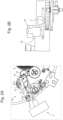
- FIG. 1 On Figure 1 on the right-hand side, a preferred embodiment of the winding device used to tension the striking mechanism is shown.
- the winding gear chain 2 By turning the winding shaft 1.1 of a conventional crown 1, the winding gear chain 2 is set in a rotary motion. This tensions a first mainspring 3 of the striking mechanism barrel 4.
- the first mainspring 3 is equipped with a slip bridle, as is known from a watch with an automatic winding mechanism.
- the same rotary motion also tensions a second mainspring (not shown) of a movement barrel 40 of the watch; this is also equipped with a slip bridle.
- Both mainsprings are thus tensioned by turning the winding shaft until the respective sliding moments are reached, and the power reserve is thus maximized, since the energy required for the striking mechanism is not reduced by the remaining power reserve.
- the advantage of the proposed combined winding is that the number of winding iterations is minimized; however, at the same time, the activation force required to turn the crown is slightly increased.
- the branch between the two winding chains takes place at the winding pinion 11, which serves as an intermediate link for winding both the striking mechanism and the running gear.
- the winding pinion 11 serves as an intermediate link for winding both the striking mechanism and the running gear.
- FIG. 1 On the left side of Figure 1 a completely separate pay-off device for the striking mechanism barrel 4 is illustrated, which is completely decoupled from this winding mechanism.
- a driven wheel 5 is in direct engagement with the striking mechanism barrel 4.
- a pay-off gear chain 9 is in engagement with the driven wheel 5, at the end of which there is a pay-off regulator 10.
- This pay-off regulator 10 can be a drum brake, a centrifugal governor, a magnetic governor or another element that regulates the speed of the gear chain 9.
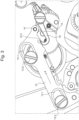
- the release lever 12 further comprises two guide notches 13.1, in each of which a shoulder screw 13.2 is screwed for fastening to the work plate, and restricts the movement of the release lever 12 slidingly along the first arrow direction "a", this direction corresponding to the longitudinal direction of the guide notches 13.1.
- a sliding guide device 13 is formed between two stops, which each determine a first so-called rest position, and a second so-called working position.
- the rest position is on Figure 2A whereas the working position is Figure 3 as indicated by the opposite position of the shoulder screw 13.2 in their respective guide notches 13.1.
- the proposed control mechanism offers an additional locking device in which an integrated trigger lock is ensured as soon as the pusher 0 has been actuated.
- the trigger lever 12 will remain in its working position until the end of the striking mechanism cycle, even if the pusher 0 is preferably brought back to its rest position by a return spring and could therefore be actuated again. However, such further actuation would then no longer have any effect.
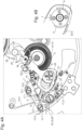
- Figure 4A shows what the sliding movement of the release lever 12 between its rest position and its working position causes.
- the shoulder screws 13.2 are located in the middle of the elongated openings of the guide notches 13.1.
- the release lever 12 On the way to the maximum working position along the first arrow direction "a", the release lever 12 must overcome a restoring force exerted by the release return spring 12.3 along the second opposite arrow direction "a'". In doing so, the release lever 12 rotates a switching cam 17 in the third arrow direction "b" with a preferably integrally formed spring element 12.1, whereby the restoring force exerted by the switching cam spring 17.2 in the fourth opposite arrow direction "b'" must also be overcome.
- the repeater strike mechanism consists of a minute repeater strike mechanism, and the three racks are each connected to hour, quarter and minute indications.
- each rack is preferably provided with a hook which is held in a locked position by a corresponding latch.
- the hook 23.1 of the third rake 23 is shown, which interacts with the third pawl 20.
- the other hooks, which are in other lower circuit diagrams, are hidden underneath.
- the third rake 23 is provided with an internal toothing 23.2, which is to be driven by the minute program wheel 8, as will be shown later with the help of Figure 5 , which explains the sequence of the striking mechanism after determining the current time.
- the internal teeth 23.2 of the third rack 23, and indeed the internal teeth of all racks, must be able to pass the program wheels without being blocked by them.
- the movement of the striking mechanism barrel 4 in this middle position of the trigger lever 12 between the rest position and the working position is limited by the pins - ie the first pin 14 and the second pin 15 - still blocked, and since the drive wheel 5 is in the power flow between the striking mechanism barrel 4 and the second pin 15, this wheel and thus all program wheels mounted on it are also still blocked.
- Figure 4B shows the position in which the driven wheel 5 must be so that neither the hour program wheel 6, nor the quarter program wheel 7, nor the minute program wheel 8 can prevent the racks from falling onto the scale.
- the rest position of this driven wheel 5 is determined during assembly depending on the rotational position of the second pin 15 and the transmission ratios in the output gear in such a way that there is no toothing in the lower angular segment of the program wheels. This means that the inner toothing of the racks can never come into engagement with the program wheels during this sequence of releasing the racks, but only later when the striking mechanism barrel 4 is no longer blocked.
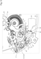
- the spring element 12.1 releases the switching finger 17.1 of the switching cam 17. This moves due to the restoring force of the switching cam spring 17.2 shown in the opposite direction to the third arrow "b", i.e. in the fourth arrow direction "b' " into its rest position.
- the release lever 12 should be held in its maximum working position by the stop pawl 16 as soon as it has reached this position.
- the release lever 12 is now in such a position on the left side of Figure 5 , in which it allows the free running of the barrel.
- d i.e. the direction of travel of the striking mechanism barrel
- a release surface 23.3 arranged on the third rake 23 begins to lift the stop pawl 16 with the aid of an adjusting eccentric 35 shortly before the third rake 23 reaches its end position, where the hook 23.1 is again in engagement with the third pawl 20.
- the adjusting eccentric 35 is preferably designed on the opposite side of the pivot axis 16.1 of the stop pawl 16.
- the tip of the stop pawl 16 thereby moves away from the holding tip 12.2 of the release lever 12. This can then return to its rest position in the second arrow direction "a'" opposite to the first arrow direction "a”, driven by the release return spring 12.3, which is only partially shown here.
- the spring element 12.1 which drives the switching cam 17 when the striking mechanism is triggered, jumps back over the switching finger 17.1 in order to stand in front of it in the rest position of the trigger lever.
- the mechanism has now returned to its original position and the repetition can be triggered again by pressing button 0.
- the invention presented here makes it possible to have a watch with a repeater striking mechanism strike several times in succession.
- the mainspring of the striking mechanism only needs to be re-tensioned after a certain number of repetitions.
- the proposed integrated trigger lock prevents the repeater from being triggered again while it is already striking, offering increased robustness and reliability, while the modular design of the trigger lock device allows the reuse of common parts of a movement (i.e. barrel & pushers), thus keeping manufacturing costs and integration costs in existing movements as low as possible.
- the subject of the present invention includes other variants both for the release lock and for the decoupling between the release device and the winding device, and is not only adapted to a minute repeater but can be applied to all types of repeater mechanisms. It is particularly possible to apply the invention presented to all types of repeaters known in watchmaking, such as quarter repeaters or minute repeaters.
- the barrel could be blocked, for example, by the pivoting movement of a rocker that would engage directly with the external gear teeth of the barrel or another wheel, rather than by the cooperation between pins; conversely, the locking of the release lever in its working position could involve a pin rather than a point.
- the release device intended to enable the release lever to return at the end of the striking mechanism's cycle does not necessarily have to take the form of a release surface arranged on a minute rake and an adjustment eccentric, but generally has to be coupled to the very last control element actuated so that this release only takes place after all the notes have been struck.
- Activating the repeater using a normal pusher is more convenient for haptic reasons than the sliders used previously, but other actuating elements, such as a bezel that should then be turned instead of pressed, would also be conceivable within the scope of the invention.
- the winding element which should not necessarily take the form of a normal crown, but can also be formed by another pusher, for example, whereby the sliding movement of the pusher should then later be converted into a rotary movement in a gear chain.
Landscapes
- Physics & Mathematics (AREA)
- General Physics & Mathematics (AREA)
- Measurement Of Unknown Time Intervals (AREA)
- Portable Nailing Machines And Staplers (AREA)
- Measurement Of Predetermined Time Intervals (AREA)
- Percussive Tools And Related Accessories (AREA)
Claims (9)
- Mouvement, comprenant :- une sonnerie à répétition, comprenant un barillet de sonnerie (4), et- un mécanisme de commande, comportant :caractérisé en ce que• un organe d'actionnement pour le déclenchement de ladite sonnerie à répétition• un dispositif d'arrêt de déclenchement, qui est activé automatiquement immédiatement après le déclenchement de ladite sonnerie à répétition, et qui est disposé dans une chaîne cinématique entre ledit organe d'actionnement et le barillet de sonnerie (4), dans lequel le dispositif d'arrêt de déclenchement présente un levier de déclenchement (12), qui est mobile entre une position de repos et une position de travail, et présente une première cheville (14), afin de bloquer la marche dudit barillet de sonnerie (4) dans la position de repos, et de libérer la marche dudit barillet de sonnerie (4) dans la position de travail,
ledit levier de déclenchement (12) est pourvu d'au moins une entrée de guidage (13.1), dans laquelle est introduite une vis à tête plate (13.2), afin de réaliser un dispositif de guidage à glissement (13). - Mouvement selon la revendication 1, dans lequel une chaîne d'engrenage de marche (9) est également disposée entre ledit organe d'actionnement et le barillet de sonnerie (4), caractérisé en ce que ladite première cheville (14) dudit levier de déclenchement (12) coopère avec une deuxième cheville (15) appliquée sur une roue de ladite chaîne d'engrenage de marche (9), afin de bloquer la marche dudit barillet de sonnerie (4) dans la position de repos, et de libérer la marche dudit barillet de sonnerie (4) dans la position de travail.
- Mouvement selon la revendication 1 ou 2, dans lequel ledit levier de déclenchement (12) présente en outre une pointe de maintien (12.2), qui coopère avec un cliquet de retenue (16), afin de verrouiller ledit levier de déclenchement (12) dans la position de travail pendant la marche du barillet de sonnerie (4).
- Mouvement selon l'une quelconque des revendications 1 à 3, dans lequel ledit levier de déclenchement (12) présente en outre un élément sur ressort (12.1), qui est responsable de la détermination de l'heure exacte, avant que la marche dudit barillet de sonnerie (4) ne soit libérée.
- Mouvement selon la revendication 4, dans lequel l'élément sur ressort (12.1) provoque sur la course entre la position de repos et la position de travail un déplacement de pivotement d'une came de commutation (17) pourvue de cliquets, qui dans la position de repos sont en prise avec des crochets de râteaux, et ainsi laissent tomber les râteaux pourvus de crochets sur leurs limaçons respectifs.
- Mouvement selon la revendication 5, dans lequel la sonnerie à répétition est une sonnerie à répétition minute, qui fait sonner 3 différents sons respectivement pour les heures, quarts et minutes, caractérisé en ce que le mécanisme de commande présente pour cela trois roues de programme dédiées, et ce une roue de programme des heures (6), une roue de programme des quarts (7), et une roue de programme des minutes (8), dans lequel les dentures desdites roues de programme viennent en prise respectivement avec la denture intérieure d'un premier râteau (21), d'un deuxième râteau (22), et d'un troisième râteau (23), qui tombent respectivement sur un limaçon des heures (26), limaçon des quarts (25) et limaçon des minutes (24) pour la détermination de l'heure.
- Mouvement selon la revendication 6, dans lequel le mécanisme de commande présente une roue menée (5) modulaire, qui se trouve dans le flux de forces entre le barillet de sonnerie (4) et une chaîne d'engrenage de marche (9), sur laquelle les différentes roues de programme, c'est-à-dire ladite roue de programme des heures (6), ladite roue de programme des quarts (7), et ladite roue de programme des minutes (8) sont empilées, qui présentent respectivement des dentures étagées et viennent en prise avec la denture intérieure desdits premier râteau (21), deuxième râteau (22) et troisièmes râteau (23) opposés lors de la marche du barillet de sonnerie (4), caractérisé en ce que la position de repos de ladite roue menée (5) lorsque le barillet de sonnerie est bloqué est définie en fonction de la position de ladite première cheville (14) et des rapports de transmission de ladite chaîne d'engrenage de marche (9), de telle sorte que les dentures intérieures desdits premier râteau (21), deuxième râteau (22) et troisième râteau (23) peuvent passer devant les différentes roues de programme, lorsque lesdits râteaux (21, 22, 23) tombent sur leurs limaçons (24, 25, 26) respectifs.
- Mouvement selon la revendication 6 ou 7, caractérisé en ce que ledit troisième râteau (23) présente une surface de déverrouillage (23.3), qui coopère avec un excentrique de réglage (35) disposé sur le cliquet de retenue (16) sur la course dudit levier de déclenchement (12) revenant de sa position de travail vers sa position de repos, afin de soulever le cliquet de retenue (16) et ainsi de permettre le retour dudit levier de déclenchement (12) dans sa position de repos.
- Mouvement selon l'une quelconque des revendications 1 à 8, dans lequel le mécanisme de commande présente des chaînes cinématiques entièrement séparées d'une part entre l'organe d'actionnement et un barillet de sonnerie (4), et d'autre part entre un remontoir séparé et ledit barillet de sonnerie (4).
Priority Applications (4)
| Application Number | Priority Date | Filing Date | Title |
|---|---|---|---|
| EP15159705.1A EP3070543B1 (fr) | 2015-03-18 | 2015-03-18 | Mecanisme à répétition doté d'un verrouillage de déclenchement intégré |
| JP2016047888A JP6093065B2 (ja) | 2015-03-18 | 2016-03-11 | リピーター機構及び一体的にされた解放ロックを備える制御機構を有する計時器 |
| US15/070,634 US9557715B2 (en) | 2015-03-18 | 2016-03-15 | Timepiece comprising a repeater mechanism and a control mechanism with an integrated release lock |
| CN201610158161.2A CN105988353B (zh) | 2015-03-18 | 2016-03-18 | 包括问表机构和具有一体的释放锁定装置的控制机构的钟表 |
Applications Claiming Priority (1)
| Application Number | Priority Date | Filing Date | Title |
|---|---|---|---|
| EP15159705.1A EP3070543B1 (fr) | 2015-03-18 | 2015-03-18 | Mecanisme à répétition doté d'un verrouillage de déclenchement intégré |
Publications (2)
| Publication Number | Publication Date |
|---|---|
| EP3070543A1 EP3070543A1 (fr) | 2016-09-21 |
| EP3070543B1 true EP3070543B1 (fr) | 2024-11-27 |
Family
ID=52692518
Family Applications (1)
| Application Number | Title | Priority Date | Filing Date |
|---|---|---|---|
| EP15159705.1A Active EP3070543B1 (fr) | 2015-03-18 | 2015-03-18 | Mecanisme à répétition doté d'un verrouillage de déclenchement intégré |
Country Status (4)
| Country | Link |
|---|---|
| US (1) | US9557715B2 (fr) |
| EP (1) | EP3070543B1 (fr) |
| JP (1) | JP6093065B2 (fr) |
| CN (1) | CN105988353B (fr) |
Families Citing this family (14)
| Publication number | Priority date | Publication date | Assignee | Title |
|---|---|---|---|---|
| CN101233552B (zh) * | 2005-07-29 | 2010-05-19 | 夏普株式会社 | 显示装置 |
| EP3070540B1 (fr) * | 2015-03-18 | 2017-11-15 | Glashütter Uhrenbetrieb GmbH | Sonnerie de montre avec marteau doté d'une butée à ressort réglable |
| CH711475B1 (fr) * | 2015-08-31 | 2019-09-30 | Blancpain Sa | Pièce d'horlogerie à sonnerie. |
| EP3327518B1 (fr) * | 2016-11-29 | 2020-03-18 | Montres Breguet S.A. | Pièce d'horlogerie comprenant un dispositif de commutation d'un mécanisme horloger |
| EP3376305B1 (fr) * | 2017-03-17 | 2020-07-22 | Harry Winston SA | Dispositif de remontage a poussoir pour montre |
| CH713604A1 (fr) * | 2017-03-22 | 2018-09-28 | Sa De La Manufacture Dhorlogerie Audemars Piguet & Cie | Mécanisme de sélection et d'actionnement ainsi que dispositif de réglage de fonctions d'une pièce d'horlogerie. |
| EP3489760B1 (fr) * | 2017-11-22 | 2020-08-26 | Harry Winston SA | Boîte d'horlogerie avec poussoir |
| EP3489765B1 (fr) * | 2017-11-23 | 2021-03-10 | Blancpain SA | Montre avec mécanisme de sonnerie à régulateur et sécurité de mise à l'heure |
| EP3502801B1 (fr) | 2017-12-19 | 2021-02-17 | Omega SA | Mécanisme de répetition chronographe avec sécurité |
| EP3502802B1 (fr) * | 2017-12-19 | 2021-02-17 | Omega SA | Mécanisme de répetition chronographe avec sécurité |
| EP3502795B1 (fr) * | 2017-12-22 | 2020-09-23 | Montres Breguet S.A. | Mécanisme de répetition à chaîne tendue |
| EP3825781B1 (fr) * | 2019-11-20 | 2022-05-25 | Chopard Technologies SA | Mécanisme de sonnerie pour pièce d'horlogerie |
| EP3825778B1 (fr) * | 2019-11-21 | 2023-07-12 | The Swatch Group Research and Development Ltd | Couronne de commande pour piece d'horlogerie |
| EP4350450B1 (fr) * | 2022-10-06 | 2026-03-18 | Montres Jaquet Droz SA | Module d'horlogerie actionnable ponctuellement comprenant des moyens de blocage automatique |
Citations (1)
| Publication number | Priority date | Publication date | Assignee | Title |
|---|---|---|---|---|
| CH684455GA3 (fr) * | 1993-02-04 | 1994-09-30 | Technowatch Sa | Pièce d'horlogerie à répétition à minutes. |
Family Cites Families (13)
| Publication number | Priority date | Publication date | Assignee | Title |
|---|---|---|---|---|
| CH61476A (fr) * | 1912-10-10 | 1913-10-01 | Louis Piguet Henri | Mouvement de montre à grande sonnerie et à répétition |
| CH487447A (fr) * | 1966-07-21 | 1969-11-28 | Jaccard Rene Philippe | Pièce d'horlogerie à réveil |
| DE3323420C2 (de) * | 1983-06-29 | 1986-10-16 | Joseph Kieninger Uhrenfabrik GmbH, 7209 Aldingen | Schlagwerksuhr mit Vorrichtung zum Abschalten des Schlagwerkes |
| JP4598363B2 (ja) * | 2001-03-21 | 2010-12-15 | グラスヒュッター・ウーレンベトリープ・ゲーエムベーハー | 時間に関連する機能の始動と同時にバレルばねを巻き上げるための機構を含む時計 |
| EP1402322B1 (fr) * | 2001-03-21 | 2009-05-27 | Glashütter Uhrenbetrieb GmbH | Piece d'horlogerie comportant un dispositif de sonnerie |
| EP1394637B1 (fr) * | 2002-08-27 | 2006-04-26 | Frédéric Piguet S.A. | Pièce d'horlogerie telle que montre-bracelet comprenant un mécanisme de réveil |
| ATE516523T1 (de) * | 2006-04-12 | 2011-07-15 | Montres Breguet Sa | Uhr mit schlagwerk, das ein einziges federhaus umfasst |
| CN201017185Y (zh) * | 2007-03-29 | 2008-02-06 | 天津中鸥表业集团有限公司 | 机械报时手表的报时启动机构 |
| CN100543616C (zh) * | 2007-03-29 | 2009-09-23 | 天津海鸥表业集团有限公司 | 一种机械报时手表的报时启动机构 |
| EP2133758A1 (fr) * | 2008-06-12 | 2009-12-16 | Blancpain S.A. | Pièce d'horlogerie comportant un mécanisme de sonnerie |
| CN201464820U (zh) * | 2009-07-02 | 2010-05-12 | 天津海鸥表业集团有限公司 | 机械报时手表的防水机构 |
| EP2498148B1 (fr) * | 2011-03-08 | 2017-11-15 | Montres Breguet SA | Mécanisme de sécurité contre des manipulations intempestives de commande d'une répétition minutes |
| CN103472705B (zh) * | 2012-06-07 | 2015-12-23 | 天津海鸥表业集团有限公司 | 一种机械报时手表的启动机构 |
-
2015
- 2015-03-18 EP EP15159705.1A patent/EP3070543B1/fr active Active
-
2016
- 2016-03-11 JP JP2016047888A patent/JP6093065B2/ja active Active
- 2016-03-15 US US15/070,634 patent/US9557715B2/en active Active
- 2016-03-18 CN CN201610158161.2A patent/CN105988353B/zh active Active
Patent Citations (2)
| Publication number | Priority date | Publication date | Assignee | Title |
|---|---|---|---|---|
| CH684455GA3 (fr) * | 1993-02-04 | 1994-09-30 | Technowatch Sa | Pièce d'horlogerie à répétition à minutes. |
| CH684455B5 (fr) * | 1993-02-04 | 1995-03-31 | Technowatch Sa | Pièce d'horlogerie à répétition à minutes. |
Also Published As
| Publication number | Publication date |
|---|---|
| JP6093065B2 (ja) | 2017-03-08 |
| US9557715B2 (en) | 2017-01-31 |
| US20160274548A1 (en) | 2016-09-22 |
| CN105988353A (zh) | 2016-10-05 |
| CN105988353B (zh) | 2019-12-17 |
| JP2016176934A (ja) | 2016-10-06 |
| EP3070543A1 (fr) | 2016-09-21 |
Similar Documents
| Publication | Publication Date | Title |
|---|---|---|
| EP3070543A1 (fr) | Carillon à répétition doté d'un verrouillage de déclenchement intégré | |
| DE60314156T2 (de) | Chronometerhemmung für Armbanduhren | |
| DE69000228T2 (de) | Analoganzeigeeinheit fuer ein uhrwerk. | |
| DE60205763T2 (de) | Timepiece provided with striking mechanism | |
| EP1491972A1 (fr) | Montre avec fonction rattrapante et mécanisme rattrapant correspondant | |
| CH713659A1 (de) | Uhr mit digitaler Zeitanzeige. | |
| EP3070535B1 (fr) | Barillet ayant un couple de rotation essentiellement constant | |
| DE2206046B2 (de) | Uhr mit einer von hand betaetigbaren stellwelle | |
| DE2856756A1 (de) | Quarzuhr mit analoganzeige und manuell betaetigbarer zeitwechselvorrichtung | |
| DE2131610C3 (de) | Uhrwerk | |
| DE2929091A1 (de) | Schlagwerk fuer eine uhr | |
| EP1584997A2 (fr) | Chronographe | |
| DE1242512B (de) | Anzeigevorrichtung an einer Uhr zum Anzeigen einer Vielzahl von Kalenderinformationen | |
| EP3070542A1 (fr) | Carillon à répétition doté d'engrenages de déclenchement et de remontage dédiés | |
| CH710898A2 (de) | Repetitionsschlagwerk mit integrierter Auslösesperre. | |
| DE69829486T2 (de) | Ewige kalenderuhr | |
| DE7002292U (de) | Uhr mit einem manuell verstellbaren zeitzonen-einstellmechanismus. | |
| DE2418690A1 (de) | Automatische kalenderuhr | |
| DE69714700T2 (de) | Anzeigevorrichtung mit springendem Sekundenzeiger | |
| DE964966C (de) | Schaltuhr, insbesondere fuer Tarifschaltung | |
| DE844750C (de) | Waehler fuer Fernmeldeanlagen | |
| DE69721741T2 (de) | Kupplungsmechanismus in einem Uhrwerkzahnradgetriebe | |
| DE730103C (de) | Schlagwerk fuer Synchronuhren | |
| DE578005C (de) | Uhr mit Stundenschlag- und Viertelwerk | |
| DE264240C (fr) |
Legal Events
| Date | Code | Title | Description |
|---|---|---|---|
| PUAI | Public reference made under article 153(3) epc to a published international application that has entered the european phase |
Free format text: ORIGINAL CODE: 0009012 |
|
| AK | Designated contracting states |
Kind code of ref document: A1 Designated state(s): AL AT BE BG CH CY CZ DE DK EE ES FI FR GB GR HR HU IE IS IT LI LT LU LV MC MK MT NL NO PL PT RO RS SE SI SK SM TR |
|
| AX | Request for extension of the european patent |
Extension state: BA ME |
|
| STAA | Information on the status of an ep patent application or granted ep patent |
Free format text: STATUS: REQUEST FOR EXAMINATION WAS MADE |
|
| 17P | Request for examination filed |
Effective date: 20170321 |
|
| RBV | Designated contracting states (corrected) |
Designated state(s): AL AT BE BG CH CY CZ DE DK EE ES FI FR GB GR HR HU IE IS IT LI LT LU LV MC MK MT NL NO PL PT RO RS SE SI SK SM TR |
|
| STAA | Information on the status of an ep patent application or granted ep patent |
Free format text: STATUS: EXAMINATION IS IN PROGRESS |
|
| 17Q | First examination report despatched |
Effective date: 20180815 |
|
| P01 | Opt-out of the competence of the unified patent court (upc) registered |
Effective date: 20230531 |
|
| GRAP | Despatch of communication of intention to grant a patent |
Free format text: ORIGINAL CODE: EPIDOSNIGR1 |
|
| STAA | Information on the status of an ep patent application or granted ep patent |
Free format text: STATUS: GRANT OF PATENT IS INTENDED |
|
| RIC1 | Information provided on ipc code assigned before grant |
Ipc: G04F 7/08 20060101ALI20240624BHEP Ipc: G04B 21/02 20060101ALI20240624BHEP Ipc: G04B 21/06 20060101ALI20240624BHEP Ipc: G04B 21/12 20060101AFI20240624BHEP |
|
| INTG | Intention to grant announced |
Effective date: 20240712 |
|
| GRAS | Grant fee paid |
Free format text: ORIGINAL CODE: EPIDOSNIGR3 |
|
| GRAA | (expected) grant |
Free format text: ORIGINAL CODE: 0009210 |
|
| STAA | Information on the status of an ep patent application or granted ep patent |
Free format text: STATUS: THE PATENT HAS BEEN GRANTED |
|
| AK | Designated contracting states |
Kind code of ref document: B1 Designated state(s): AL AT BE BG CH CY CZ DE DK EE ES FI FR GB GR HR HU IE IS IT LI LT LU LV MC MK MT NL NO PL PT RO RS SE SI SK SM TR |
|
| REG | Reference to a national code |
Ref country code: GB Ref legal event code: FG4D Free format text: NOT ENGLISH |
|
| REG | Reference to a national code |
Ref country code: CH Ref legal event code: EP |
|
| REG | Reference to a national code |
Ref country code: IE Ref legal event code: FG4D Free format text: LANGUAGE OF EP DOCUMENT: GERMAN |
|
| REG | Reference to a national code |
Ref country code: DE Ref legal event code: R096 Ref document number: 502015016987 Country of ref document: DE |
|
| REG | Reference to a national code |
Ref country code: DE Ref legal event code: R081 Ref document number: 502015016987 Country of ref document: DE Owner name: GLASHUETTER UHRENBETRIEB GMBH - GLASHUETTE/SA., DE Free format text: FORMER OWNER: GLASHUETTER UHRENBETRIEB GMBH, 01768 GLASHUETTE, DE Ref country code: DE Ref legal event code: R081 Ref document number: 502015016987 Country of ref document: DE Owner name: GLASHUETTER UHRENBETRIEB GMBH - GLASHUETTE/SA., DE Free format text: FORMER OWNER: ANMELDERANGABEN UNKLAR / UNVOLLSTAENDIG, 80297 MUENCHEN, DE |
|
| REG | Reference to a national code |
Ref country code: LT Ref legal event code: MG9D |
|
| REG | Reference to a national code |
Ref country code: NL Ref legal event code: MP Effective date: 20241127 |
|
| PG25 | Lapsed in a contracting state [announced via postgrant information from national office to epo] |
Ref country code: HR Free format text: LAPSE BECAUSE OF FAILURE TO SUBMIT A TRANSLATION OF THE DESCRIPTION OR TO PAY THE FEE WITHIN THE PRESCRIBED TIME-LIMIT Effective date: 20241127 Ref country code: IS Free format text: LAPSE BECAUSE OF FAILURE TO SUBMIT A TRANSLATION OF THE DESCRIPTION OR TO PAY THE FEE WITHIN THE PRESCRIBED TIME-LIMIT Effective date: 20250327 Ref country code: PT Free format text: LAPSE BECAUSE OF FAILURE TO SUBMIT A TRANSLATION OF THE DESCRIPTION OR TO PAY THE FEE WITHIN THE PRESCRIBED TIME-LIMIT Effective date: 20250327 |
|
| PG25 | Lapsed in a contracting state [announced via postgrant information from national office to epo] |
Ref country code: FI Free format text: LAPSE BECAUSE OF FAILURE TO SUBMIT A TRANSLATION OF THE DESCRIPTION OR TO PAY THE FEE WITHIN THE PRESCRIBED TIME-LIMIT Effective date: 20241127 Ref country code: NL Free format text: LAPSE BECAUSE OF FAILURE TO SUBMIT A TRANSLATION OF THE DESCRIPTION OR TO PAY THE FEE WITHIN THE PRESCRIBED TIME-LIMIT Effective date: 20241127 |
|
| PG25 | Lapsed in a contracting state [announced via postgrant information from national office to epo] |
Ref country code: BG Free format text: LAPSE BECAUSE OF FAILURE TO SUBMIT A TRANSLATION OF THE DESCRIPTION OR TO PAY THE FEE WITHIN THE PRESCRIBED TIME-LIMIT Effective date: 20241127 |
|
| PG25 | Lapsed in a contracting state [announced via postgrant information from national office to epo] |
Ref country code: ES Free format text: LAPSE BECAUSE OF FAILURE TO SUBMIT A TRANSLATION OF THE DESCRIPTION OR TO PAY THE FEE WITHIN THE PRESCRIBED TIME-LIMIT Effective date: 20241127 |
|
| PG25 | Lapsed in a contracting state [announced via postgrant information from national office to epo] |
Ref country code: NO Free format text: LAPSE BECAUSE OF FAILURE TO SUBMIT A TRANSLATION OF THE DESCRIPTION OR TO PAY THE FEE WITHIN THE PRESCRIBED TIME-LIMIT Effective date: 20250227 |
|
| PG25 | Lapsed in a contracting state [announced via postgrant information from national office to epo] |
Ref country code: LV Free format text: LAPSE BECAUSE OF FAILURE TO SUBMIT A TRANSLATION OF THE DESCRIPTION OR TO PAY THE FEE WITHIN THE PRESCRIBED TIME-LIMIT Effective date: 20241127 Ref country code: GR Free format text: LAPSE BECAUSE OF FAILURE TO SUBMIT A TRANSLATION OF THE DESCRIPTION OR TO PAY THE FEE WITHIN THE PRESCRIBED TIME-LIMIT Effective date: 20250228 |
|
| PG25 | Lapsed in a contracting state [announced via postgrant information from national office to epo] |
Ref country code: PL Free format text: LAPSE BECAUSE OF FAILURE TO SUBMIT A TRANSLATION OF THE DESCRIPTION OR TO PAY THE FEE WITHIN THE PRESCRIBED TIME-LIMIT Effective date: 20241127 |
|
| PG25 | Lapsed in a contracting state [announced via postgrant information from national office to epo] |
Ref country code: RS Free format text: LAPSE BECAUSE OF FAILURE TO SUBMIT A TRANSLATION OF THE DESCRIPTION OR TO PAY THE FEE WITHIN THE PRESCRIBED TIME-LIMIT Effective date: 20250227 |
|
| PG25 | Lapsed in a contracting state [announced via postgrant information from national office to epo] |
Ref country code: SM Free format text: LAPSE BECAUSE OF FAILURE TO SUBMIT A TRANSLATION OF THE DESCRIPTION OR TO PAY THE FEE WITHIN THE PRESCRIBED TIME-LIMIT Effective date: 20241127 |
|
| PG25 | Lapsed in a contracting state [announced via postgrant information from national office to epo] |
Ref country code: DK Free format text: LAPSE BECAUSE OF FAILURE TO SUBMIT A TRANSLATION OF THE DESCRIPTION OR TO PAY THE FEE WITHIN THE PRESCRIBED TIME-LIMIT Effective date: 20241127 |
|
| PG25 | Lapsed in a contracting state [announced via postgrant information from national office to epo] |
Ref country code: EE Free format text: LAPSE BECAUSE OF FAILURE TO SUBMIT A TRANSLATION OF THE DESCRIPTION OR TO PAY THE FEE WITHIN THE PRESCRIBED TIME-LIMIT Effective date: 20241127 |
|
| PG25 | Lapsed in a contracting state [announced via postgrant information from national office to epo] |
Ref country code: RO Free format text: LAPSE BECAUSE OF FAILURE TO SUBMIT A TRANSLATION OF THE DESCRIPTION OR TO PAY THE FEE WITHIN THE PRESCRIBED TIME-LIMIT Effective date: 20241127 |
|
| PG25 | Lapsed in a contracting state [announced via postgrant information from national office to epo] |
Ref country code: SK Free format text: LAPSE BECAUSE OF FAILURE TO SUBMIT A TRANSLATION OF THE DESCRIPTION OR TO PAY THE FEE WITHIN THE PRESCRIBED TIME-LIMIT Effective date: 20241127 |
|
| PG25 | Lapsed in a contracting state [announced via postgrant information from national office to epo] |
Ref country code: CZ Free format text: LAPSE BECAUSE OF FAILURE TO SUBMIT A TRANSLATION OF THE DESCRIPTION OR TO PAY THE FEE WITHIN THE PRESCRIBED TIME-LIMIT Effective date: 20241127 |
|
| PG25 | Lapsed in a contracting state [announced via postgrant information from national office to epo] |
Ref country code: IT Free format text: LAPSE BECAUSE OF FAILURE TO SUBMIT A TRANSLATION OF THE DESCRIPTION OR TO PAY THE FEE WITHIN THE PRESCRIBED TIME-LIMIT Effective date: 20241127 |
|
| REG | Reference to a national code |
Ref country code: DE Ref legal event code: R097 Ref document number: 502015016987 Country of ref document: DE |
|
| PG25 | Lapsed in a contracting state [announced via postgrant information from national office to epo] |
Ref country code: SE Free format text: LAPSE BECAUSE OF FAILURE TO SUBMIT A TRANSLATION OF THE DESCRIPTION OR TO PAY THE FEE WITHIN THE PRESCRIBED TIME-LIMIT Effective date: 20241127 |
|
| REG | Reference to a national code |
Ref country code: DE Ref legal event code: R119 Ref document number: 502015016987 Country of ref document: DE |
|
| PLBE | No opposition filed within time limit |
Free format text: ORIGINAL CODE: 0009261 |
|
| STAA | Information on the status of an ep patent application or granted ep patent |
Free format text: STATUS: NO OPPOSITION FILED WITHIN TIME LIMIT |
|
| REG | Reference to a national code |
Ref country code: CH Ref legal event code: L10 Free format text: ST27 STATUS EVENT CODE: U-0-0-L10-L00 (AS PROVIDED BY THE NATIONAL OFFICE) Effective date: 20251008 |
|
| PG25 | Lapsed in a contracting state [announced via postgrant information from national office to epo] |
Ref country code: MC Free format text: LAPSE BECAUSE OF FAILURE TO SUBMIT A TRANSLATION OF THE DESCRIPTION OR TO PAY THE FEE WITHIN THE PRESCRIBED TIME-LIMIT Effective date: 20241127 |
|
| REG | Reference to a national code |
Ref country code: CH Ref legal event code: H13 Free format text: ST27 STATUS EVENT CODE: U-0-0-H10-H13 (AS PROVIDED BY THE NATIONAL OFFICE) Effective date: 20251023 |
|
| REG | Reference to a national code |
Ref country code: CH Ref legal event code: K11 Free format text: ST27 STATUS EVENT CODE: U-0-0-K10-K11 (AS PROVIDED BY THE NATIONAL OFFICE) Effective date: 20251029 Ref country code: CH Ref legal event code: U11 Free format text: ST27 STATUS EVENT CODE: U-0-0-U10-U11 (AS PROVIDED BY THE NATIONAL OFFICE) Effective date: 20251029 |
|
| 26N | No opposition filed |
Effective date: 20250828 |
|
| PG25 | Lapsed in a contracting state [announced via postgrant information from national office to epo] |
Ref country code: LU Free format text: LAPSE BECAUSE OF NON-PAYMENT OF DUE FEES Effective date: 20250318 |
|
| GBPC | Gb: european patent ceased through non-payment of renewal fee |
Effective date: 20250318 |
|
| REG | Reference to a national code |
Ref country code: BE Ref legal event code: MM Effective date: 20250331 |
|
| REG | Reference to a national code |
Ref country code: DE Ref legal event code: R073 Ref document number: 502015016987 Country of ref document: DE |
|
| PG25 | Lapsed in a contracting state [announced via postgrant information from national office to epo] |
Ref country code: DE Free format text: LAPSE BECAUSE OF NON-PAYMENT OF DUE FEES Effective date: 20251001 |
|
| PG25 | Lapsed in a contracting state [announced via postgrant information from national office to epo] |
Ref country code: GB Free format text: LAPSE BECAUSE OF NON-PAYMENT OF DUE FEES Effective date: 20250318 |
|
| PG25 | Lapsed in a contracting state [announced via postgrant information from national office to epo] |
Ref country code: FR Free format text: LAPSE BECAUSE OF NON-PAYMENT OF DUE FEES Effective date: 20250331 |
|
| PG25 | Lapsed in a contracting state [announced via postgrant information from national office to epo] |
Ref country code: BE Free format text: LAPSE BECAUSE OF NON-PAYMENT OF DUE FEES Effective date: 20250331 |
|
| PG25 | Lapsed in a contracting state [announced via postgrant information from national office to epo] |
Ref country code: IE Free format text: LAPSE BECAUSE OF NON-PAYMENT OF DUE FEES Effective date: 20250318 |
|
| REG | Reference to a national code |
Ref country code: DE Ref legal event code: R074 Ref document number: 502015016987 Country of ref document: DE |
|
| REG | Reference to a national code |
Ref country code: CH Ref legal event code: U11 Free format text: ST27 STATUS EVENT CODE: U-0-0-U10-U11 (AS PROVIDED BY THE NATIONAL OFFICE) Effective date: 20260401 |
|
| PG25 | Lapsed in a contracting state [announced via postgrant information from national office to epo] |
Ref country code: DE Free format text: LAPSE BECAUSE OF NON-PAYMENT OF DUE FEES Effective date: 20251001 |
|
| PGFP | Annual fee paid to national office [announced via postgrant information from national office to epo] |
Ref country code: DE Payment date: 20260219 Year of fee payment: 12 |
|
| PGRI | Patent reinstated in contracting state [announced from national office to epo] |
Ref country code: DE Effective date: 20260202 |
|
| REG | Reference to a national code |
Ref country code: AT Ref legal event code: MM01 Ref document number: 1746261 Country of ref document: AT Kind code of ref document: T Effective date: 20250318 |
|
| PG25 | Lapsed in a contracting state [announced via postgrant information from national office to epo] |
Ref country code: CY Free format text: LAPSE BECAUSE OF FAILURE TO SUBMIT A TRANSLATION OF THE DESCRIPTION OR TO PAY THE FEE WITHIN THE PRESCRIBED TIME-LIMIT Effective date: 20241127 |
|
| PG25 | Lapsed in a contracting state [announced via postgrant information from national office to epo] |
Ref country code: LT Free format text: LAPSE BECAUSE OF FAILURE TO SUBMIT A TRANSLATION OF THE DESCRIPTION OR TO PAY THE FEE WITHIN THE PRESCRIBED TIME-LIMIT Effective date: 20241127 |
|
| PG25 | Lapsed in a contracting state [announced via postgrant information from national office to epo] |
Ref country code: TR Free format text: LAPSE BECAUSE OF FAILURE TO SUBMIT A TRANSLATION OF THE DESCRIPTION OR TO PAY THE FEE WITHIN THE PRESCRIBED TIME-LIMIT Effective date: 20241127 |
|
| PG25 | Lapsed in a contracting state [announced via postgrant information from national office to epo] |
Ref country code: AT Free format text: LAPSE BECAUSE OF NON-PAYMENT OF DUE FEES Effective date: 20250318 |
|
| PGFP | Annual fee paid to national office [announced via postgrant information from national office to epo] |
Ref country code: CH Payment date: 20260401 Year of fee payment: 12 |