EP3070723A2 - Dispositif de transmission de donnees et d'energie entre deux objets se deplaçant l'un par rapport a l'autre - Google Patents
Dispositif de transmission de donnees et d'energie entre deux objets se deplaçant l'un par rapport a l'autre Download PDFInfo
- Publication number
- EP3070723A2 EP3070723A2 EP16159897.4A EP16159897A EP3070723A2 EP 3070723 A2 EP3070723 A2 EP 3070723A2 EP 16159897 A EP16159897 A EP 16159897A EP 3070723 A2 EP3070723 A2 EP 3070723A2
- Authority
- EP
- European Patent Office
- Prior art keywords
- coil
- electrical
- circuit board
- printed circuit
- electrical conductor
- Prior art date
- Legal status (The legal status is an assumption and is not a legal conclusion. Google has not performed a legal analysis and makes no representation as to the accuracy of the status listed.)
- Granted
Links
Images


Classifications
-
- H—ELECTRICITY
- H02—GENERATION; CONVERSION OR DISTRIBUTION OF ELECTRIC POWER
- H02J—ELECTRIC POWER NETWORKS; CIRCUIT ARRANGEMENTS OR SYSTEMS FOR SUPPLYING OR DISTRIBUTING ELECTRIC POWER; SYSTEMS FOR STORING ELECTRIC ENERGY
- H02J50/00—Circuit arrangements or systems for wireless supply or distribution of electric power
- H02J50/10—Circuit arrangements or systems for wireless supply or distribution of electric power using inductive coupling
-
- H—ELECTRICITY
- H01—ELECTRIC ELEMENTS
- H01F—MAGNETS; INDUCTANCES; TRANSFORMERS; SELECTION OF MATERIALS FOR THEIR MAGNETIC PROPERTIES
- H01F27/00—Details of transformers or inductances, in general
-
- H—ELECTRICITY
- H01—ELECTRIC ELEMENTS
- H01F—MAGNETS; INDUCTANCES; TRANSFORMERS; SELECTION OF MATERIALS FOR THEIR MAGNETIC PROPERTIES
- H01F38/00—Adaptations of transformers or inductances for specific applications or functions
- H01F38/14—Inductive couplings
-
- H—ELECTRICITY
- H04—ELECTRIC COMMUNICATION TECHNIQUE
- H04B—TRANSMISSION
- H04B5/00—Near-field transmission systems, e.g. inductive or capacitive transmission systems
- H04B5/20—Near-field transmission systems, e.g. inductive or capacitive transmission systems characterised by the transmission technique; characterised by the transmission medium
- H04B5/24—Inductive coupling
- H04B5/26—Inductive coupling using coils
-
- H—ELECTRICITY
- H01—ELECTRIC ELEMENTS
- H01F—MAGNETS; INDUCTANCES; TRANSFORMERS; SELECTION OF MATERIALS FOR THEIR MAGNETIC PROPERTIES
- H01F38/00—Adaptations of transformers or inductances for specific applications or functions
- H01F38/14—Inductive couplings
- H01F2038/143—Inductive couplings for signals
Definitions
- the invention relates to a device for the contactless transmission of data and energy between two relatively moving objects about a common axis of rotation, wherein the first article comprises a first coil and the second article comprises a second coil, wherein the coils are so axially with respect to the axis of rotation spaced apart that energy transfer by inductive coupling between the two coils is possible.
- the invention further relates to a laser scanner with such a device.
- Another application is found, for example, in corresponding embodiments of laser scanners for monitoring an environment.
- Energy and data signals are exchanged here, for example, between a rotating sensor head and a stationary evaluation and supply unit.
- DE 195 32 043 A1 describes a steering wheel for a vehicle, in which between the steering column and the relatively rotating steering wheel energy is ensured via an inductive coupling of corresponding coil systems.
- For signal transmission sees the DE 195 32 043 A1 the transmission on an inductive basis or on an opto-electrical basis.
- the opto-electrical transmission according to DE 195 32 043 A1 requires additional optical elements.
- the possible data rates for inductive transmission of data are very limited in their height. So usually a maximum of several 10 kbit are possible, which is not sufficient for many applications.
- DE 44 07 277 A1 describes a transformer for energy between two relatively rotating elements.
- two coil carriers in the form of printed circuit boards, on each of which coil windings are provided which are essentially concentric with the axis of rotation of the relative movement and which serve to transmit energy via an inductive coupling between the two relatively moving objects.
- the coils are penetrated by ferrite cores, which cause or promote the magnetic coupling.
- This arrangement is according to DE 44 07 277 A1 also used for information transmission.
- DE 10 2014 105 261 B3 describes a device for transmitting data and energy between two mutually rotating objects. On two mutually rotating circuit boards coil windings are provided by means of which energy is transmitted inductively. Data transmission takes place via electrodes, which are also provided on the circuit board and concentric with the coil windings.
- DE 10 2014 105 261 B3 describes a device having the features of the preamble of claim 1.
- the device according to the invention for the transmission of data and energy between two objects which move relative to one another about a common axis of rotation has a first coil on the first article and a second coil on the second article.
- the second coil is the first coil axially spaced relative to the axis of rotation with respect to that a contactless energy transfer by inductive coupling between the two coils is possible.
- a first disk or disc-shaped electrode carrier Coaxially with and rotatably with the first coil, a first disk or disc-shaped electrode carrier is provided with a first electrical conductor. Coaxial with and non-rotatable with the second coil, a second disc or disc-shaped electrode carrier opposite the first electrode carrier is provided with a second electrical conductor.
- the electrode supports are axially spaced from each other and the first and the second electrical conductor are arranged such that a data transmission by contactless electrical coupling between the first and the second electrical conductor is possible.
- electrical coupling between the first and the second electrical conductor is thus to be understood here as a contactless capacitive coupling.
- the coil or coils are concentric with the axis of rotation of the relative movement of the objects, whereby the arrangement according to the invention is simple and easy to handle.
- the electrical conductors for data transmission are designed circular or part-circular, wherein the circles or pitch circles are concentric to the axis of rotation of the relative movement.
- the first article comprises a first disc-shaped or annular-disc-shaped coil carrier carrying the first coil
- the second article comprises a second disc-shaped or annular-disc-shaped coil carrier carrying the second coil.
- Such disc or annular disc-shaped coil carriers are easy to manufacture and can be used e.g. be processed by lithographic processes to apply the coils on it.
- the coils on the disc or annular disc-shaped coil carrier are axially spaced from each other to the inductive To enable coupling to the energy transfer.
- the coil carrier are designed in the invention directly as printed circuit boards on which the respective coil windings are applied for energy transfer.
- the electrode carrier circuit boards on which the electrical conductors are applied for data transmission are produced on printed circuit boards very simply by lithographic processes known per se (eg vapor deposition or etching).
- the geometry of the coil turns or the electrical conductor can be fixed in a simple manner and the circuit boards can themselves serve as a carrier for the coil windings and the electrical conductors.
- the first coil carrier and the first electrode carrier are integrally provided (ie can be formed by one part) and the second coil carrier and the second electrode carrier are in one piece. In this way, only one printed circuit board per item must be provided in each case. On this circuit board, the energy transmission coil and the electrical conductor for data transmission are then provided, respectively, and may be used in the manufacture e.g. be processed simultaneously.
- the coil carriers or the electrode carriers are provided as printed circuit boards, it is possible in a space-saving manner to provide further components, especially electronic components, and connecting lines.
- the coils are designed flat. That is, they include coil turns which are juxtaposed on a surface of the respective disc or annular disc-shaped bobbin.
- the coil turns of the first coil (on the first object) and the coil turns of the second coil (on the second object) are opposite on the opposite sides of the two coil support, as also below with reference to the in the figures embodiment shown is described.
- an arrangement of conductive material for electrical shielding is also provided between the first coil and the first electrical conductor and / or between the second coil and the second electrical conductor, in each case coaxially between coil and conductor. It is thus possible in an effective manner, in spite of the compact arrangement of the device, to effectively limit disturbances in the data transmission via the electrical conductors through the adjacently arranged inductive energy transmission via the coils. Nevertheless, a small design is possible because the inductive energy transfer and the electrical data transmission need not be physically far apart to prevent the otherwise occurring electromagnetic interference.
- the inner peripheries of the holes in the printed circuit boards are coated with metallic material to a To effect shielding, which can be realized in a simple manner, without weakening the support structure too much.
- the device has a first housing shell of conductive material and / or a second housing shell of conductive material, wherein the first housing shell is non-rotatable with the first article and the second housing shell is non-rotatable with the second article.
- the housing shells of conductive material serve to electrically shield the system from the outside and effectively prevent interference from external influences.
- such arranged and configured housing shells provide a connection to the virtual ground by causing a capacitive coupling between the real ground and the virtual ground.
- first housing shell is electrically connected to the electrical arrangement between the coil turns of the first coil and the first electrical conductor and the second housing shell electrically connected to the electrical arrangement of conductive material for electrical shielding between the coil turns of the second coil and is connected to the second electrical conductor.
- the shielding arrangements between the respective coil turns and electrodes are electrically connected to a respective housing shell, so that an effective shielding of the data transmission against any external influences and in particular also against the influences of the coils used for energy transmission is provided. Only that side of the electrode carrier that directly faces the electrode carrier on the other relatively rotating object is not surrounded by the shield.
- connection may be made, for example, by a conductive annular structure, e.g. be formed conductive foam, which is arranged coaxially to the axis of rotation between the coil and the electrode.
- a conductive annular structure e.g. be formed conductive foam
- the shielding by the housing shells when the two housing shells at their radially outer region each comprise an angled region, wherein the angled portions of the two housing shells radially spaced from each other are adjacent.
- region of the respective coil carrier on which the respective coil is located surrounds at least on its radially outer circumference an arrangement of magnetic material and / or is arranged in its radially interior. If the coil carriers of each of the objects moving relative to one another have a corresponding arrangement of magnetic material, the inductive coupling for energy transmission is effectively amplified by the transforming effect.
- a corresponding arrangement of magnetic material which surrounds the region of the coil carrier, have a further shielding effect, which prevents the inductive energy transmission from adversely affecting the electrical data transmission.
- this magnetic arrangement is made of soft magnetic materials, in particular "ferrite".
- the arrangement of magnetic material on the respective object has a particularly effective and effective effect if it has a circular or part-circular section concentric with the axis of rotation of the relative movement of the articles, which passes through the printed circuit board, and / or a second circle concentric with the axis of rotation of the relative movement of the objects - or part-circular portion which passes through the circuit board and has a larger radius than the first section.
- a drive motor for generating the relative movement of the two objects or the drive shaft of a corresponding drive motor passes through the printed circuit boards in order to ensure the most compact possible construction.
- a substantially rotationally symmetrical about the axis of rotation of the relative movement arrangement and configuration of the individual elements of the device according to the invention and its preferred embodiments is advantageous because of the ease of manufacture, ease of use and ease of operation.
- the device according to the invention and its particularly preferred embodiments due to the good shielding, in particular between the data-transmitting electrodes and the energy-transmitting coils, enables data transmission in the single-digit 100 MHz range at data rates of about 30 Mbit, which allows more cost-effective and power-saving operation than if data transmission in the GHz range is provided.
- the device according to the invention can be used particularly advantageously for the transmission of energy and data in laser scanners in which a sensor head rotates relative to a supply unit.
- a sensor head rotates relative to a supply unit.
- the compact design and yet precise data transmission is advantageous, which can be achieved by the inventive device for the transmission of energy and data and their advantageous embodiments.
- Fig. 1 shows an embodiment of a device according to the invention in a lateral section in a schematic representation.
- the lateral section you can see two opposing circuit boards 10, 110, which are mutually movable about the axis A relative to each other.
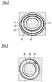
- Fig. 2 shows in particular the printed circuit board 10 in a viewing direction, the in Fig. 1 from below would be. Thus, one sees here that side of the printed circuit board 10 which faces the printed circuit boards 110.
- a coil 14 with coil windings which are substantially concentric with the axis of rotation A of the relative movement.
- These coil turns are on average the Fig. 1 shown schematically as only a black bar at the bottom of the printed circuit board section 10 '.
- Fig. 2 is the coil on the circuit board in the area 10 'not shown.
- the coil turns are formed on the respective printed circuit board by vapor-deposited or etched tracks.
- the same reference numeral 14 is used in the present text for the sake of simplicity.
- an electrode 12 which is arranged concentrically to the axis of rotation A as a conductor ring.
- the printed circuit board 10 is connected via one or more insulating spacers 16 (FIG. Fig. 1 ) is connected to a metallic housing shell 22, which may comprise, for example, a deep-drawn sheet metal.
- this housing shell 22 is rotatably connected to the drive shaft 52 of a drive motor 50, so that the housing shell 22 rotates together with the circuit board 10 and the structures applied thereto.
- a shield structure 18, 20 is provided, which is configured in the described embodiment as follows:
- a ring arranged holes 20 are located radially opposite the electrode 12 inwardly offset on a ring arranged holes 20, the interior of which is metallically lined, e.g. by a corresponding evaporation process.
- These metal-lined holes 20 are connected via a metallic material 18 with the housing shell 22 in electrical connection.
- the metallic material 18 may be e.g. to act on conductive foam.
- the housing shell 22 on the radially outer side of the printed circuit board 10 an angled portion 26. Overall, this results in a shielding structure, which is formed from the metal-lined holes 20, the annular material structure 18, the planar surface of the housing shell 22 and the angled portion 26 of the housing shell 22.
- a housing shell 122 is fixedly mounted in the described embodiment.
- This housing shell 122 carries a structure that the described structure, which is provided in the housing shell 22, corresponds and faces her.
- an electrode 112 is provided on a printed circuit board area of a printed circuit board 110, which is connected to the housing shell 122 via one or more insulating spacers 116.
- An annular structure of metallic foam 118 connects the housing shell 122 with holes 120 which are annularly arranged in the printed circuit board 110 and are lined with metal. At the radially outermost region of the housing shell 122, this has an angled region 126.
- the opposing electrodes 12 and 112 on the facing printed circuit boards 10 and 110, respectively are effectively shielded by the shield structure formed by the housing shells 22, 122, their angled portions 26, 126, the metallic foam structures 18 , 118 and the metal-lined annular holes 20, 120 is formed.
- the shielding is particularly effective to the outside if, as in the embodiment shown, the angled regions 26, 126 of the two housing shells 22, 122 overlap.
- the housing shells 22, 122 and in particular the angled portions 26, 126 also still form an effective capacitive coupling of the mass between the relatively rotating elements.
- the already described lithographically produced coil windings 14 are provided on the printed circuit board area 10 '. These coil windings 14 are on the in Fig. 1 lower printed circuit board 110 in the area 110 'coil turns 114 opposite, which are made lithographically the same as the coil turns 14 on the respective printed circuit board.
- the same reference numeral 114 is used herein for the coil on the circuit board 110 and the coil turns forming it.
- the printed circuit board area 10 ' is surrounded by a ferrite structure 24, which in Fig. 3 is shown isolated. It can be seen that this structure has angled regions 30, 32 which pass through the printed circuit board 10 '( Fig. 1 ). In this case, the outer angled portion 32 only at the areas on cut-outs, through which pass through the web portions of the printed circuit board 10, which connect the printed circuit board area 10 'with the rest of the printed circuit board.
- the ferrite structure 24 in this way cooperates particularly effectively with a ferrite structure 124 on the other printed circuit board 110.
- the second ferrite structure 124 encloses the printed circuit card region 110 'of the second printed circuit board 110 in the same way as the ferrite structure 24 the printed circuit board region 10' of the printed circuit board 10.
- the inductive coupling between the opposing coils 14, 114 through the ferrite structures 24, 124 effectively amplified transformer.
- the ferrite structures 24, 124 additionally have a shielding effect in such a way that the electrical coupling of the electrodes 12, 112 for data transmission is not or less disturbed by the inductive coupling between the coils 14 and 114.
- the relatively rotating structures thus include corresponding opposing elements, wherein in Fig. 1 the elements of the second Structure repeats the numerals of the first structure ("xx") with an imaginary one (“1 xx").
- the housing shell 22, the printed circuit board 10, the electrode 12 and the coil turns 14 move together with the ferrite core 24 about the axis of rotation A. These elements thus form the "rotor", while the stationary elements form the “stator” of the assembly.
- the housing shell 122 is connected to the motor 50.
- the printed circuit board 110 with the electrode 112 and the coil turns 114 do not move.
- there is a relative rotational movement between the coil windings 14 and 114 which provide an inductive coupling for energy transfer.
- the opposing electrodes 12 and 112 are used for data transmission between the relatively rotating elements A about the axis.
- the drive motor 50 may be provided with the stationary housing shell 122 on the stationary part of a laser scanner, while the housing shell 22 rotates with the associated elements together with the drive shaft 52 relative thereto.
- the drive shaft 52 then e.g. be connected to the sensor head of the laser scanner.
- the device according to the invention then effectively enables the energy transfer via the inductive coupling between the coils 14 and 114 and the data transmission from the sensor head to the stationary elements of the laser scanner via the electrodes 12 and 112.
- the data transfer via the electrodes 12, 112 is described radially outside the energy transfer via the coil windings 14, 114.
- the shielding between the data transmission electrodes and the energy transmission coils such an arrangement is analogous to the one described above.
Landscapes
- Engineering & Computer Science (AREA)
- Power Engineering (AREA)
- Computer Networks & Wireless Communication (AREA)
- Signal Processing (AREA)
- Near-Field Transmission Systems (AREA)
Applications Claiming Priority (1)
| Application Number | Priority Date | Filing Date | Title |
|---|---|---|---|
| DE102015103823.4A DE102015103823A1 (de) | 2015-03-16 | 2015-03-16 | Vorrichtung zur Übertragung von Daten und Energie zwischen zwei sich relativ zueinander bewegenden Gegenständen |
Publications (3)
| Publication Number | Publication Date |
|---|---|
| EP3070723A2 true EP3070723A2 (fr) | 2016-09-21 |
| EP3070723A3 EP3070723A3 (fr) | 2016-11-02 |
| EP3070723B1 EP3070723B1 (fr) | 2017-07-19 |
Family
ID=55527859
Family Applications (1)
| Application Number | Title | Priority Date | Filing Date |
|---|---|---|---|
| EP16159897.4A Active EP3070723B1 (fr) | 2015-03-16 | 2016-03-11 | Dispositif de transmission de donnees et d'energie entre deux objets se deplaçant l'un par rapport a l'autre |
Country Status (4)
| Country | Link |
|---|---|
| US (1) | US10263468B2 (fr) |
| EP (1) | EP3070723B1 (fr) |
| JP (1) | JP6209236B2 (fr) |
| DE (1) | DE102015103823A1 (fr) |
Cited By (3)
| Publication number | Priority date | Publication date | Assignee | Title |
|---|---|---|---|---|
| CN109804443A (zh) * | 2016-10-06 | 2019-05-24 | Lg伊诺特有限公司 | 用于无线充电的线圈组件及其制造方法 |
| WO2023246968A1 (fr) * | 2022-06-22 | 2023-12-28 | Schaeffler Technologies AG & Co. KG | Appareil d'enregistrement de valeurs mesurées dans une machine et de transmission sans contact de signaux, et ensemble machine équipé d'un tel appareil |
| US11940563B2 (en) | 2019-10-25 | 2024-03-26 | Sick Ag | Sensor and method for manufacturing an inductive energy transmission unit |
Families Citing this family (24)
| Publication number | Priority date | Publication date | Assignee | Title |
|---|---|---|---|---|
| WO2017174359A1 (fr) * | 2016-04-04 | 2017-10-12 | Tecflower Ag | Accumulateur d'énergie rechargeable sans fil |
| US10084349B2 (en) * | 2017-02-15 | 2018-09-25 | Apple Inc. | Inductive module |
| DE102017218676B4 (de) * | 2017-10-19 | 2023-03-23 | Robert Bosch Gmbh | LIDAR-Sensor mit einer Vorrichtung zur kontaktlosen Übertragung von Daten und von Energie und zur Winkelmessung |
| US11340336B2 (en) * | 2017-12-07 | 2022-05-24 | Ouster, Inc. | Rotating light ranging system with optical communication uplink and downlink channels |
| CN110033931B (zh) * | 2018-01-12 | 2021-10-29 | 乾坤科技股份有限公司 | 电子装置及其制作方法 |
| US20210159736A1 (en) * | 2018-03-29 | 2021-05-27 | Panasonic Intellectual Property Management Co., Ltd. | Transmission module and wireless power data transmission device |
| JP7019492B2 (ja) * | 2018-04-04 | 2022-02-15 | Nittoku株式会社 | 製造装置 |
| DE102018111182B4 (de) * | 2018-05-09 | 2023-02-02 | Schaeffler Technologies AG & Co. KG | Kupplung mit einer elektrisch betriebenen Betätigungseinrichtung |
| KR102700029B1 (ko) * | 2018-07-30 | 2024-08-29 | 삼성전자주식회사 | 복수의 무선 충전 코일들을 포함하는 전자 장치 및 그 동작 방법 |
| CN108964286B (zh) * | 2018-08-17 | 2023-12-01 | 天津工业大学 | 一种大功率动态耦合无线输电的电滑环 |
| CN109617248A (zh) * | 2018-12-25 | 2019-04-12 | 无锡格跃科技有限公司 | 无线供电及无线通讯装置 |
| JPWO2020174819A1 (fr) * | 2019-02-28 | 2020-09-03 | ||
| CN109756031B (zh) * | 2019-03-01 | 2021-03-16 | 西安电子科技大学 | 同轴结构的无线能量耦合器 |
| DE102019007229B4 (de) | 2019-10-17 | 2024-10-31 | Krebs & Aulich Gmbh | Anordnung zur kontaktlosen Energie- und Signalübertragung an einer Rotorwelle einer Elektromaschine |
| WO2021094576A1 (fr) | 2019-11-14 | 2021-05-20 | Schleifring Gmbh | Joint rotatif intégré compact doté d'un blindage résonant |
| JP2021141748A (ja) * | 2020-03-06 | 2021-09-16 | Smk株式会社 | ワイヤレス給電装置 |
| CN111371204B (zh) * | 2020-03-25 | 2021-10-26 | 维沃移动通信有限公司 | 充电方法及电能中转装置 |
| DE202020105330U1 (de) | 2020-03-26 | 2020-10-08 | Amphenol-Tuchel Electronics Gmbh | Energieübertragungsvorrichtung |
| DE102020108422A1 (de) | 2020-03-26 | 2021-09-30 | Amphenol-Tuchel Electronics Gesellschaft mit beschränkter Haftung | Energieübertragungsvorrichtung |
| BE1028203B1 (de) * | 2020-04-09 | 2021-11-08 | Phoenix Contact Gmbh & Co | Kopplungseinrichtung zur drahtlosen Daten- und Energieübertragung sowie ein Kopplungssystem zur drahtlosen Daten- und Energieübertragung |
| US12184080B2 (en) | 2020-12-09 | 2024-12-31 | Panasonic Intellectual Property Management Co., Ltd. | Wireless power supply unit and wireless power transmission system |
| WO2022243010A1 (fr) * | 2021-05-17 | 2022-11-24 | Atlas Copco Industrial Technique Ab | Outil électrique avec capacité de transfert de signal sans fil |
| DE102021212145B4 (de) * | 2021-10-27 | 2026-01-15 | Mahle International Gmbh | Elektrischer Drehtransformator zur induktiven Energieübertragung und fremderregte elektrische Synchronmaschine |
| JP7455168B2 (ja) * | 2021-10-28 | 2024-03-25 | キストラー ホールディング アクチエンゲゼルシャフト | トルク及び回転角度検出システム |
Citations (4)
| Publication number | Priority date | Publication date | Assignee | Title |
|---|---|---|---|---|
| DE4120650A1 (de) | 1991-06-22 | 1992-12-24 | Kolbenschmidt Ag | Vorrichtung zur uebertragung von elektrischer energie und daten in kraftfahrzeugen |
| DE4407277A1 (de) | 1993-03-24 | 1994-09-29 | Siemens Ag | Elektrischer Übertrager |
| DE19532043A1 (de) | 1995-08-31 | 1997-03-06 | Marquardt Gmbh | Lenkrad für ein Kraftfahrzeug |
| DE102014105261B3 (de) | 2014-04-14 | 2015-02-19 | Sick Ag | Optoelektronischer Sensor und Verfahren zur Erfassung von Objekten in einem Überwachungsbereich |
Family Cites Families (16)
| Publication number | Priority date | Publication date | Assignee | Title |
|---|---|---|---|---|
| JPS4997713U (fr) * | 1972-12-15 | 1974-08-22 | ||
| JPS4997713A (fr) | 1973-01-23 | 1974-09-17 | ||
| JPS5944017U (ja) * | 1982-09-14 | 1984-03-23 | 日本フエライト株式会社 | 回転トランスのシヨ−トリング取り付け構造 |
| JPS59155715U (ja) * | 1983-04-05 | 1984-10-19 | 三菱電機株式会社 | ロ−タリ−トランス |
| JPS61174703A (ja) * | 1985-01-30 | 1986-08-06 | Pioneer Electronic Corp | 回転トランスの製造方法 |
| JP2970037B2 (ja) * | 1991-05-14 | 1999-11-02 | 松下電器産業株式会社 | ロータリートランス |
| JPH11354346A (ja) * | 1998-06-04 | 1999-12-24 | Furukawa Electric Co Ltd:The | 分離トランス |
| JP3644310B2 (ja) * | 1999-06-15 | 2005-04-27 | Necトーキン株式会社 | 非接触型トランス |
| JP4758700B2 (ja) * | 2005-07-22 | 2011-08-31 | 三重電子株式会社 | 無接触式伝送装置 |
| JP2008249375A (ja) * | 2007-03-29 | 2008-10-16 | Topcon Corp | 3次元位置測定装置 |
| DE102007042659C5 (de) * | 2007-09-10 | 2016-01-21 | Sew-Eurodrive Gmbh & Co Kg | Koppeleinrichtung |
| EP2688078A1 (fr) * | 2012-07-17 | 2014-01-22 | Stichting Nationaal Lucht- en Ruimtevaart Laboratorium | Alimentation et transfert de données sans contact |
| WO2015108153A1 (fr) * | 2014-01-20 | 2015-07-23 | 日立オートモティブシステムズ株式会社 | Appareil d'alimentation électrique sans contact et capteur de couple |
| HUE041536T2 (hu) * | 2014-01-20 | 2019-05-28 | Hitachi Automotive Systems Ltd | Érintkezésmentes energiaellátó berendezés forgó testekhez, és nyomatékérzékelõ |
| US10447079B2 (en) * | 2014-04-18 | 2019-10-15 | Apple Inc. | Multi-coil induction |
| US9583260B2 (en) * | 2014-07-23 | 2017-02-28 | Goodrich Corporation | System and method for increasing coupling of an axle rotary transformer |
-
2015
- 2015-03-16 DE DE102015103823.4A patent/DE102015103823A1/de not_active Withdrawn
-
2016
- 2016-03-09 JP JP2016046007A patent/JP6209236B2/ja active Active
- 2016-03-11 EP EP16159897.4A patent/EP3070723B1/fr active Active
- 2016-03-15 US US15/070,244 patent/US10263468B2/en active Active
Patent Citations (4)
| Publication number | Priority date | Publication date | Assignee | Title |
|---|---|---|---|---|
| DE4120650A1 (de) | 1991-06-22 | 1992-12-24 | Kolbenschmidt Ag | Vorrichtung zur uebertragung von elektrischer energie und daten in kraftfahrzeugen |
| DE4407277A1 (de) | 1993-03-24 | 1994-09-29 | Siemens Ag | Elektrischer Übertrager |
| DE19532043A1 (de) | 1995-08-31 | 1997-03-06 | Marquardt Gmbh | Lenkrad für ein Kraftfahrzeug |
| DE102014105261B3 (de) | 2014-04-14 | 2015-02-19 | Sick Ag | Optoelektronischer Sensor und Verfahren zur Erfassung von Objekten in einem Überwachungsbereich |
Cited By (3)
| Publication number | Priority date | Publication date | Assignee | Title |
|---|---|---|---|---|
| CN109804443A (zh) * | 2016-10-06 | 2019-05-24 | Lg伊诺特有限公司 | 用于无线充电的线圈组件及其制造方法 |
| US11940563B2 (en) | 2019-10-25 | 2024-03-26 | Sick Ag | Sensor and method for manufacturing an inductive energy transmission unit |
| WO2023246968A1 (fr) * | 2022-06-22 | 2023-12-28 | Schaeffler Technologies AG & Co. KG | Appareil d'enregistrement de valeurs mesurées dans une machine et de transmission sans contact de signaux, et ensemble machine équipé d'un tel appareil |
Also Published As
| Publication number | Publication date |
|---|---|
| JP2016174149A (ja) | 2016-09-29 |
| JP6209236B2 (ja) | 2017-10-04 |
| US10263468B2 (en) | 2019-04-16 |
| EP3070723B1 (fr) | 2017-07-19 |
| US20160276871A1 (en) | 2016-09-22 |
| DE102015103823A1 (de) | 2016-09-22 |
| EP3070723A3 (fr) | 2016-11-02 |
Similar Documents
| Publication | Publication Date | Title |
|---|---|---|
| EP3070723B1 (fr) | Dispositif de transmission de donnees et d'energie entre deux objets se deplaçant l'un par rapport a l'autre | |
| EP3179638B1 (fr) | Dispositif de transmission sans contact de donnees et destiné à déterminer la modification angulaire entre deux objets se deplaçant l'un par rapport à l'autre | |
| EP2933655B1 (fr) | Capteur optoélectronique et procédé destiné à la détection d'objets dans une zone de surveillance | |
| EP1464935B1 (fr) | Appareil pour détecter le couple de rotation d'un arbre rotatif | |
| DE10259082B4 (de) | Elektrische Servolenkvorrichtung und Verfahren zur Herstellung derselben | |
| DE69108647T2 (de) | Ringförmiger Geschwindigkeitsmessaufnehmer. | |
| EP2893359B1 (fr) | Palier résolveur | |
| WO2015180711A1 (fr) | Palier de résolveur, stator de résolveur et procédé de fabrication | |
| EP3961174B1 (fr) | Dispositif de capteur de couple, agencement de conducteur de flux et conducteur de flux | |
| WO1992014121A1 (fr) | Dispositif de mesure de mouvement angulaire | |
| DE19529528A1 (de) | Anordnung zum kontaktlosen Übertragen von Signalen zwischen einem feststehenden und einem drehbar gelagerten Fahrzeugteil | |
| DE202015101334U1 (de) | Vorrichtung zur Übertragung von Daten und Energie zwischen zwei sich relativ zueinander bewegenden Gegenständen | |
| WO1997038876A1 (fr) | Dispositif pour la transmission inductive d'energie electrique et de signaux dans des vehicules automobiles | |
| DE2848173A1 (de) | Sensoranordnung | |
| DE102013111405A1 (de) | Steckverbindungseinheit zur Verbindung einer Kabelschaltung mit einemSensormodul | |
| EP0735632A2 (fr) | Dispositif de transmission de signaux entre deux terminaux | |
| EP3104128B1 (fr) | Dispositif de transmission sans contact de donnees et destine a determiner la modification angulaire entre deux objets se deplaçant l'un par rapport a l'autre | |
| EP3179217B1 (fr) | Dispositif de transmission sans contact de donnees et destiné à déterminer la modification angulaire entre deux objets se deplaçant l'un par rapport à l'autre | |
| DE922417C (de) | Abstimmbares Magnetron mit einer Vielfachhohlraum-Anode | |
| DE4125143C2 (de) | Einrichtung zur kontaktlosen Übertragung von Wechselsignalen | |
| DE102017218676B4 (de) | LIDAR-Sensor mit einer Vorrichtung zur kontaktlosen Übertragung von Daten und von Energie und zur Winkelmessung | |
| EP3179637A2 (fr) | Dispositif de transmission sans contact de donnees et destiné à déterminer la modification angulaire entre deux objets se deplaçant l'un par rapport à l'autre | |
| DE69420795T2 (de) | Rotierender Transformator | |
| EP2383755B1 (fr) | Composant à induction | |
| DE102024111300B4 (de) | Sensoranordnung an einer elektrischen Maschine und Aktuator für eine steer-by-wire-Anordnung |
Legal Events
| Date | Code | Title | Description |
|---|---|---|---|
| PUAI | Public reference made under article 153(3) epc to a published international application that has entered the european phase |
Free format text: ORIGINAL CODE: 0009012 |
|
| AK | Designated contracting states |
Kind code of ref document: A2 Designated state(s): AL AT BE BG CH CY CZ DE DK EE ES FI FR GB GR HR HU IE IS IT LI LT LU LV MC MK MT NL NO PL PT RO RS SE SI SK SM TR |
|
| AX | Request for extension of the european patent |
Extension state: BA ME |
|
| PUAL | Search report despatched |
Free format text: ORIGINAL CODE: 0009013 |
|
| AK | Designated contracting states |
Kind code of ref document: A3 Designated state(s): AL AT BE BG CH CY CZ DE DK EE ES FI FR GB GR HR HU IE IS IT LI LT LU LV MC MK MT NL NO PL PT RO RS SE SI SK SM TR |
|
| AX | Request for extension of the european patent |
Extension state: BA ME |
|
| RIC1 | Information provided on ipc code assigned before grant |
Ipc: H01F 27/00 20060101AFI20160923BHEP |
|
| STAA | Information on the status of an ep patent application or granted ep patent |
Free format text: STATUS: REQUEST FOR EXAMINATION WAS MADE |
|
| 17P | Request for examination filed |
Effective date: 20161107 |
|
| RBV | Designated contracting states (corrected) |
Designated state(s): AL AT BE BG CH CY CZ DE DK EE ES FI FR GB GR HR HU IE IS IT LI LT LU LV MC MK MT NL NO PL PT RO RS SE SI SK SM TR |
|
| GRAP | Despatch of communication of intention to grant a patent |
Free format text: ORIGINAL CODE: EPIDOSNIGR1 |
|
| STAA | Information on the status of an ep patent application or granted ep patent |
Free format text: STATUS: GRANT OF PATENT IS INTENDED |
|
| INTG | Intention to grant announced |
Effective date: 20170112 |
|
| RIN1 | Information on inventor provided before grant (corrected) |
Inventor name: KUFNER, MARTIN Inventor name: KERP, MICHAEL Inventor name: SCHMITZ, STEPHAN Inventor name: SZERBAKOWSKI, BORIS Inventor name: HUBER, GREGOR |
|
| GRAS | Grant fee paid |
Free format text: ORIGINAL CODE: EPIDOSNIGR3 |
|
| GRAA | (expected) grant |
Free format text: ORIGINAL CODE: 0009210 |
|
| STAA | Information on the status of an ep patent application or granted ep patent |
Free format text: STATUS: THE PATENT HAS BEEN GRANTED |
|
| AK | Designated contracting states |
Kind code of ref document: B1 Designated state(s): AL AT BE BG CH CY CZ DE DK EE ES FI FR GB GR HR HU IE IS IT LI LT LU LV MC MK MT NL NO PL PT RO RS SE SI SK SM TR |
|
| REG | Reference to a national code |
Ref country code: GB Ref legal event code: FG4D Free format text: NOT ENGLISH |
|
| REG | Reference to a national code |
Ref country code: CH Ref legal event code: EP |
|
| REG | Reference to a national code |
Ref country code: IE Ref legal event code: FG4D Free format text: LANGUAGE OF EP DOCUMENT: GERMAN |
|
| REG | Reference to a national code |
Ref country code: AT Ref legal event code: REF Ref document number: 911106 Country of ref document: AT Kind code of ref document: T Effective date: 20170815 |
|
| REG | Reference to a national code |
Ref country code: DE Ref legal event code: R096 Ref document number: 502016000058 Country of ref document: DE |
|
| REG | Reference to a national code |
Ref country code: NL Ref legal event code: MP Effective date: 20170719 |
|
| REG | Reference to a national code |
Ref country code: LT Ref legal event code: MG4D |
|
| PG25 | Lapsed in a contracting state [announced via postgrant information from national office to epo] |
Ref country code: NL Free format text: LAPSE BECAUSE OF FAILURE TO SUBMIT A TRANSLATION OF THE DESCRIPTION OR TO PAY THE FEE WITHIN THE PRESCRIBED TIME-LIMIT Effective date: 20170719 Ref country code: LT Free format text: LAPSE BECAUSE OF FAILURE TO SUBMIT A TRANSLATION OF THE DESCRIPTION OR TO PAY THE FEE WITHIN THE PRESCRIBED TIME-LIMIT Effective date: 20170719 Ref country code: HR Free format text: LAPSE BECAUSE OF FAILURE TO SUBMIT A TRANSLATION OF THE DESCRIPTION OR TO PAY THE FEE WITHIN THE PRESCRIBED TIME-LIMIT Effective date: 20170719 Ref country code: FI Free format text: LAPSE BECAUSE OF FAILURE TO SUBMIT A TRANSLATION OF THE DESCRIPTION OR TO PAY THE FEE WITHIN THE PRESCRIBED TIME-LIMIT Effective date: 20170719 Ref country code: SE Free format text: LAPSE BECAUSE OF FAILURE TO SUBMIT A TRANSLATION OF THE DESCRIPTION OR TO PAY THE FEE WITHIN THE PRESCRIBED TIME-LIMIT Effective date: 20170719 Ref country code: NO Free format text: LAPSE BECAUSE OF FAILURE TO SUBMIT A TRANSLATION OF THE DESCRIPTION OR TO PAY THE FEE WITHIN THE PRESCRIBED TIME-LIMIT Effective date: 20171019 |
|
| PG25 | Lapsed in a contracting state [announced via postgrant information from national office to epo] |
Ref country code: PL Free format text: LAPSE BECAUSE OF FAILURE TO SUBMIT A TRANSLATION OF THE DESCRIPTION OR TO PAY THE FEE WITHIN THE PRESCRIBED TIME-LIMIT Effective date: 20170719 Ref country code: IS Free format text: LAPSE BECAUSE OF FAILURE TO SUBMIT A TRANSLATION OF THE DESCRIPTION OR TO PAY THE FEE WITHIN THE PRESCRIBED TIME-LIMIT Effective date: 20171119 Ref country code: BG Free format text: LAPSE BECAUSE OF FAILURE TO SUBMIT A TRANSLATION OF THE DESCRIPTION OR TO PAY THE FEE WITHIN THE PRESCRIBED TIME-LIMIT Effective date: 20171019 Ref country code: GR Free format text: LAPSE BECAUSE OF FAILURE TO SUBMIT A TRANSLATION OF THE DESCRIPTION OR TO PAY THE FEE WITHIN THE PRESCRIBED TIME-LIMIT Effective date: 20171020 Ref country code: ES Free format text: LAPSE BECAUSE OF FAILURE TO SUBMIT A TRANSLATION OF THE DESCRIPTION OR TO PAY THE FEE WITHIN THE PRESCRIBED TIME-LIMIT Effective date: 20170719 Ref country code: RS Free format text: LAPSE BECAUSE OF FAILURE TO SUBMIT A TRANSLATION OF THE DESCRIPTION OR TO PAY THE FEE WITHIN THE PRESCRIBED TIME-LIMIT Effective date: 20170719 Ref country code: LV Free format text: LAPSE BECAUSE OF FAILURE TO SUBMIT A TRANSLATION OF THE DESCRIPTION OR TO PAY THE FEE WITHIN THE PRESCRIBED TIME-LIMIT Effective date: 20170719 |
|
| REG | Reference to a national code |
Ref country code: FR Ref legal event code: PLFP Year of fee payment: 3 |
|
| REG | Reference to a national code |
Ref country code: DE Ref legal event code: R097 Ref document number: 502016000058 Country of ref document: DE |
|
| PG25 | Lapsed in a contracting state [announced via postgrant information from national office to epo] |
Ref country code: DK Free format text: LAPSE BECAUSE OF FAILURE TO SUBMIT A TRANSLATION OF THE DESCRIPTION OR TO PAY THE FEE WITHIN THE PRESCRIBED TIME-LIMIT Effective date: 20170719 Ref country code: RO Free format text: LAPSE BECAUSE OF FAILURE TO SUBMIT A TRANSLATION OF THE DESCRIPTION OR TO PAY THE FEE WITHIN THE PRESCRIBED TIME-LIMIT Effective date: 20170719 Ref country code: CZ Free format text: LAPSE BECAUSE OF FAILURE TO SUBMIT A TRANSLATION OF THE DESCRIPTION OR TO PAY THE FEE WITHIN THE PRESCRIBED TIME-LIMIT Effective date: 20170719 |
|
| PLBE | No opposition filed within time limit |
Free format text: ORIGINAL CODE: 0009261 |
|
| STAA | Information on the status of an ep patent application or granted ep patent |
Free format text: STATUS: NO OPPOSITION FILED WITHIN TIME LIMIT |
|
| PG25 | Lapsed in a contracting state [announced via postgrant information from national office to epo] |
Ref country code: SK Free format text: LAPSE BECAUSE OF FAILURE TO SUBMIT A TRANSLATION OF THE DESCRIPTION OR TO PAY THE FEE WITHIN THE PRESCRIBED TIME-LIMIT Effective date: 20170719 Ref country code: EE Free format text: LAPSE BECAUSE OF FAILURE TO SUBMIT A TRANSLATION OF THE DESCRIPTION OR TO PAY THE FEE WITHIN THE PRESCRIBED TIME-LIMIT Effective date: 20170719 Ref country code: SM Free format text: LAPSE BECAUSE OF FAILURE TO SUBMIT A TRANSLATION OF THE DESCRIPTION OR TO PAY THE FEE WITHIN THE PRESCRIBED TIME-LIMIT Effective date: 20170719 Ref country code: IT Free format text: LAPSE BECAUSE OF FAILURE TO SUBMIT A TRANSLATION OF THE DESCRIPTION OR TO PAY THE FEE WITHIN THE PRESCRIBED TIME-LIMIT Effective date: 20170719 |
|
| 26N | No opposition filed |
Effective date: 20180420 |
|
| PG25 | Lapsed in a contracting state [announced via postgrant information from national office to epo] |
Ref country code: SI Free format text: LAPSE BECAUSE OF FAILURE TO SUBMIT A TRANSLATION OF THE DESCRIPTION OR TO PAY THE FEE WITHIN THE PRESCRIBED TIME-LIMIT Effective date: 20170719 |
|
| PG25 | Lapsed in a contracting state [announced via postgrant information from national office to epo] |
Ref country code: MT Free format text: LAPSE BECAUSE OF FAILURE TO SUBMIT A TRANSLATION OF THE DESCRIPTION OR TO PAY THE FEE WITHIN THE PRESCRIBED TIME-LIMIT Effective date: 20170719 |
|
| PG25 | Lapsed in a contracting state [announced via postgrant information from national office to epo] |
Ref country code: MC Free format text: LAPSE BECAUSE OF FAILURE TO SUBMIT A TRANSLATION OF THE DESCRIPTION OR TO PAY THE FEE WITHIN THE PRESCRIBED TIME-LIMIT Effective date: 20170719 |
|
| REG | Reference to a national code |
Ref country code: BE Ref legal event code: MM Effective date: 20180331 |
|
| REG | Reference to a national code |
Ref country code: IE Ref legal event code: MM4A |
|
| PG25 | Lapsed in a contracting state [announced via postgrant information from national office to epo] |
Ref country code: LU Free format text: LAPSE BECAUSE OF NON-PAYMENT OF DUE FEES Effective date: 20180311 |
|
| PG25 | Lapsed in a contracting state [announced via postgrant information from national office to epo] |
Ref country code: IE Free format text: LAPSE BECAUSE OF NON-PAYMENT OF DUE FEES Effective date: 20180311 |
|
| PG25 | Lapsed in a contracting state [announced via postgrant information from national office to epo] |
Ref country code: BE Free format text: LAPSE BECAUSE OF NON-PAYMENT OF DUE FEES Effective date: 20180331 |
|
| REG | Reference to a national code |
Ref country code: CH Ref legal event code: PL |
|
| PG25 | Lapsed in a contracting state [announced via postgrant information from national office to epo] |
Ref country code: LI Free format text: LAPSE BECAUSE OF NON-PAYMENT OF DUE FEES Effective date: 20190331 Ref country code: CH Free format text: LAPSE BECAUSE OF NON-PAYMENT OF DUE FEES Effective date: 20190331 |
|
| PG25 | Lapsed in a contracting state [announced via postgrant information from national office to epo] |
Ref country code: TR Free format text: LAPSE BECAUSE OF FAILURE TO SUBMIT A TRANSLATION OF THE DESCRIPTION OR TO PAY THE FEE WITHIN THE PRESCRIBED TIME-LIMIT Effective date: 20170719 |
|
| PG25 | Lapsed in a contracting state [announced via postgrant information from national office to epo] |
Ref country code: PT Free format text: LAPSE BECAUSE OF FAILURE TO SUBMIT A TRANSLATION OF THE DESCRIPTION OR TO PAY THE FEE WITHIN THE PRESCRIBED TIME-LIMIT Effective date: 20170719 |
|
| PG25 | Lapsed in a contracting state [announced via postgrant information from national office to epo] |
Ref country code: CY Free format text: LAPSE BECAUSE OF FAILURE TO SUBMIT A TRANSLATION OF THE DESCRIPTION OR TO PAY THE FEE WITHIN THE PRESCRIBED TIME-LIMIT Effective date: 20170719 Ref country code: MK Free format text: LAPSE BECAUSE OF NON-PAYMENT OF DUE FEES Effective date: 20170719 Ref country code: HU Free format text: LAPSE BECAUSE OF FAILURE TO SUBMIT A TRANSLATION OF THE DESCRIPTION OR TO PAY THE FEE WITHIN THE PRESCRIBED TIME-LIMIT; INVALID AB INITIO Effective date: 20160311 |
|
| PG25 | Lapsed in a contracting state [announced via postgrant information from national office to epo] |
Ref country code: AL Free format text: LAPSE BECAUSE OF FAILURE TO SUBMIT A TRANSLATION OF THE DESCRIPTION OR TO PAY THE FEE WITHIN THE PRESCRIBED TIME-LIMIT Effective date: 20170719 |
|
| GBPC | Gb: european patent ceased through non-payment of renewal fee |
Effective date: 20200311 |
|
| PG25 | Lapsed in a contracting state [announced via postgrant information from national office to epo] |
Ref country code: GB Free format text: LAPSE BECAUSE OF NON-PAYMENT OF DUE FEES Effective date: 20200311 |
|
| REG | Reference to a national code |
Ref country code: AT Ref legal event code: MM01 Ref document number: 911106 Country of ref document: AT Kind code of ref document: T Effective date: 20210311 |
|
| PG25 | Lapsed in a contracting state [announced via postgrant information from national office to epo] |
Ref country code: AT Free format text: LAPSE BECAUSE OF NON-PAYMENT OF DUE FEES Effective date: 20210311 |
|
| PGFP | Annual fee paid to national office [announced via postgrant information from national office to epo] |
Ref country code: DE Payment date: 20260320 Year of fee payment: 11 |
|
| PGFP | Annual fee paid to national office [announced via postgrant information from national office to epo] |
Ref country code: FR Payment date: 20260325 Year of fee payment: 11 |