EP3070816A1 - Procédé et dispositif pour refroidir une machine électrique - Google Patents
Procédé et dispositif pour refroidir une machine électrique Download PDFInfo
- Publication number
- EP3070816A1 EP3070816A1 EP16161326.0A EP16161326A EP3070816A1 EP 3070816 A1 EP3070816 A1 EP 3070816A1 EP 16161326 A EP16161326 A EP 16161326A EP 3070816 A1 EP3070816 A1 EP 3070816A1
- Authority
- EP
- European Patent Office
- Prior art keywords
- stator
- cooling
- electric machine
- protrusions
- ring
- Prior art date
- Legal status (The legal status is an assumption and is not a legal conclusion. Google has not performed a legal analysis and makes no representation as to the accuracy of the status listed.)
- Granted
Links
Images


Classifications
-
- H—ELECTRICITY
- H02—GENERATION; CONVERSION OR DISTRIBUTION OF ELECTRIC POWER
- H02K—DYNAMO-ELECTRIC MACHINES
- H02K1/00—Details of the magnetic circuit
- H02K1/06—Details of the magnetic circuit characterised by the shape, form or construction
- H02K1/12—Stationary parts of the magnetic circuit
- H02K1/20—Stationary parts of the magnetic circuit with channels or ducts for flow of cooling medium
-
- H—ELECTRICITY
- H02—GENERATION; CONVERSION OR DISTRIBUTION OF ELECTRIC POWER
- H02K—DYNAMO-ELECTRIC MACHINES
- H02K5/00—Casings; Enclosures; Supports
- H02K5/04—Casings or enclosures characterised by the shape, form or construction thereof
- H02K5/18—Casings or enclosures characterised by the shape, form or construction thereof with ribs or fins for improving heat transfer
-
- H—ELECTRICITY
- H02—GENERATION; CONVERSION OR DISTRIBUTION OF ELECTRIC POWER
- H02K—DYNAMO-ELECTRIC MACHINES
- H02K9/00—Arrangements for cooling or ventilating
- H02K9/02—Arrangements for cooling or ventilating by ambient air flowing through the machine
- H02K9/04—Arrangements for cooling or ventilating by ambient air flowing through the machine having means for generating a flow of cooling medium
- H02K9/06—Arrangements for cooling or ventilating by ambient air flowing through the machine having means for generating a flow of cooling medium with fans or impellers driven by the machine shaft
Definitions
- Electric machines typically comprise a stator element and a rotor element that interact electro-magnetically to convert electric power to mechanical power or to convert mechanical power to electrical power.
- a conventional stator element comprises an annular housing having windings of copper coils circumferentially oriented.
- a conventional rotor element is mounted on a shaft for rotation. Electric current is passed through the stator windings to generate an electro-magnetic field that causes the rotor and shaft to rotate about an axis of rotation of the shaft. The electric current causes resistance heating of the coils, which heats the entire electric machine including the rotor.
- high power electric motors that operate at high speeds and are compact in size generate high heat densities.
- an electric machine in one exemplary embodiment, includes a stator having a plurality of axial protrusions forming a plurality of stator cooling channels on a radially outer surface of the stator and a tapered portion located adjacent a distal end of at least one of the plurality of protrusions. Additionally, the disclosure includes a method for cooling the electric machine.
- a fan assembly 20 is driven by an electric machine 22.
- the fan assembly 20 includes a fan impeller 24, an outer housing 26, an inner housing 28, a cooling air tube 30, and an electrical conduit 32 in electrical communication with the electric machine 22.
- the electric machine 22 shown in the illustrated examples is an electric motor, this disclosure also applies to cooling an electric generator or another device that includes a stator.
- the electric machine 22 includes a shaft 34 spaced radially inward from a rotor 36 and a stator 44 spaced radially outward from the rotor 36.
- the shaft 34 is attached to the rotor 36 such that the shaft 34 and the rotor 36 rotate together.
- the shaft 34 includes a forward shaft portion 34A located axially forward from an aft shaft portion 34B relative to an axis of rotation A of the electric machine 22.
- the forward shaft portion 34A is mounted to a forward motor support 38A located within the inner housing 28 by a forward bearing assembly 40A and the aft shaft portion 34B is mounted to an aft motor support 38B located within the inner housing 28 by an aft bearing assembly 40B.
- the outer housing 26 forms an annular duct 42 with the inner housing 28 in which the fan impeller 24 is disposed to drive air through the fan assembly 20.
- the electrical conduit 32 extends through the annular duct 42 and allows access to the stator 44 by passing through the inner housing 28 and outer housing 26 to provide an electrical connection with the stator 44 and a power source.
- the cooling air tube 30 also extends through the annular duct 42 and allows cooling air C from a cooling air source outside of the fan assembly 20 to reach the electric machine 22, which is surrounded by the annular duct 42.
- the cooling air source could include room air or another air source.
- the inner housing 28 is concentrically mounted within the outer housing 26 by a support structure 46 which extends radially between a radially outer facing surface of the inner housing 28 and a radially inner facing surface of the outer housing 26.
- the forward and aft motor supports 38A and 38B are mounted to a radially inner facing surface of the inner housing 28 and include portions for supporting the stator 44 and the forward and aft bearing assemblies 40A and 40B.
- the stator 44 and the forward and aft bearing assemblies 40A and 40B are mounted to radially inward facing surfaces of motor supports 38A and 38B.
- the forward and aft shaft portions 34A and 34B are positioned within the forward and aft bearing assemblies 40A and 40B and extend axially and concentrically with the axis of rotation A.
- a tie rod 33 secures the forward shaft portion 34A relative to the aft shaft portion 34B through the application of a tensile force through the tie rod 33.
- the tie rod 33 extends through a center of the forward shaft portion 34A and a center of the aft shaft portion 34B and engages a forward end cap 48A adjacent the forward shaft portion 34A and an aft end cap 48B adjacent the aft shaft portion 34B.
- the forward end cap 48A connects the fan impeller 24 to the forward shaft portion 34A so that the fan impeller 24 will rotate with the forward and aft shaft portions 34A and 34B and the rotor 36.
- the rotor 36 is mounted to a radially outward facing surface of the aft shaft portion 34B and faces toward the stator 44.
- a small gap between the rotor 36 and the stator 44 forms a rotor cooling passage 50 that permits the cooling air C from the cooling air tube 30 to flow around the rotor 36 and through the electric machine 22.
- Electrical wiring 32A extends through the electrical conduit 32 and connects to the stator 44 to energize coil windings with electrical current.
- the energized coil windings exert an electro-magnetic flux field on the rotor 36.
- the flux field causes the rotor 36 to rotate about the axis of rotation A on the shaft 34.
- the tie rod 33 rotates with the forward and aft shafts portions 34A and 34B and the rotor 36.
- the forward and aft shaft portions 34A and 34B and the rotor 36 rotate on the forward and aft bearing assemblies 40A and 40B and cause the fan impeller 24 to rotate in the annular duct 42 and push air between the inner and outer housings 28 and 26.
- Stator cooling channels 56 allow the cooling air C to flow around a radially outer surface or back iron of the stator 44 between the stator 44 and the inner housing 28 to provide convective cooling to the stator 44.
- the stator cooling channels 56 extend an entire length of the stator 44.
- a shaft cooling passage 54 also permits the cooling air C to enter the shaft 34 through a shaft inlet 52B that extends through the aft end cap 48B.
- the cooling air C exits at the interior cavity of the shaft 34 through a shaft outlet 52A in the forward end cap 48A.
- the shaft cooling passage 54 allows the cooling air C to flow along the interior of the forward and aft shaft portions 34A and 34B to provide convective cooling to the forward and aft shaft portions 34A and 34B as well as the rotor 36.
- the tie rod 33 extends through the shaft cooling passage 54 concentrically with the forward and aft shaft portions 34A and 34B along the axis of rotation A.
- the diameter of the tie rod 33 is smaller than that of shaft cooling passage 54 such that a spacing is present between the tie rod 33 and the forward and aft shaft portions 34A and 34B, which permits the cooling air C to pass through the shaft cooling passage 54.
- the electric machine 22 is cooled by the cooling air C flowing through the shaft cooling passage 54, the rotor cooling passage 50, and the stator cooling channel 56.
- cooling air C flowing through the shaft cooling passage 54, the rotor cooling passage 50, and the stator cooling channel 56.
- other cooling fluids such as liquid or gas, may be used in other embodiments.
- the electric machine 22 is cooled by the cooling air C flowing through the shaft cooling passage 54, the rotor cooling passage 50, and the stator cooling channel 56 as parallel flow circuits.
- the incoming cooling flow C is divided amongst the shaft cooling passage 54, the rotor cooling passage 50, and the stator cooling channel 56 based on their contribution to the total flow resistance. Therefore, in order to increase cooling of the stator 44 adjacent the stator cooling channel 56, a flow rate of the cooling air C through the stator cooling channel 56 would need to increase.
- the stator cooling channels 56 are formed by pairs of protrusions 60, such as fins, that extend from a radially outer side of the stator 44 and form channels that defines each of the stator cooling channels 56.
- a radially outer side of the stator cooling channel 56 is defined by the radially inward facing surface of the motor support 38B and in another example, the radially outer side of the stator cooling channel 56 is defined by the inner housing 28.
- the perimeter of the stator cooling channels 56 are a feature of the motor laminations (thin iron plates), and the channels achieve their length when numerous laminations are stacked together to form the motor core.
- stator cooling channels 56 are formed by a series of stacked laminations that are usually die-punched from sheet stock raw material, the entrances and exits of each stator cooling channel are largely sharp-edged.
- the sharp-edge orifices at each cooling channel may lead to significant pressure-drop losses that reduce the amount of cooling flow that actually enter them.
- the distal ends of the stator cooling channel 56 taper adjacent distal ends of the protrusions 60 to form an inlet 62 and an outlet 64.
- the taper at the inlet 62 of the stator cooling channel 56 creates an area of decreasing cross-sectional area as the cooling air C enters the stator cooling channel 56.
- the change in cross-sectional area in the inlet 62 provides a gradual transition for the cooling air C entering the stator cooling channel 56 which increases the flow rate of the cooling air C into the stator cooling channel 56 by reducing the pressure drop associated with the entrance losses of sharp-edge orifices
- the outlet 64 includes an increasing cross-sectional area as the cooling air C moves from the stator cooling channel 56 out of the stator 44.
- the change in cross-sectional area in the outlet 64 provides a gradual transition for the cooling air exiting the stator cooling channel 56 which increases the flow of the cooling air C into the stator cooling channel 56 by reducing the pressure drop associated with the exit losses of sharp-edge orifices.
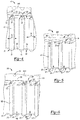
- Figure 3 illustrates a ring 66 formed by two separate ring halves and 68B that can be located on opposing ends of the stator 44 to form the inlets 62 and the outlets 64 to the stator cooling channels 56.
- the ring 66 is formed by the two ring halves 68A and 68B in the illustrated example, the ring 66 could be formed from a single piece of material or more than two pieces of material.
- the ring 66 includes a ring portion 68 and a multitude ring protrusions 70 that extend radially outward from the ring portion 68 and are circumferentially spaced around an outer perimeter of the ring portion 68.
- the ring 66 attaches to a distal end 44A of the stator 44.
- the ring protrusions 70 are circumferentially aligned with a corresponding one of the protrusions 60 on the stator 44.
- Each of the ring protrusions 70 include a first axial face 72 that engages one of the protrusions 60 on the stator 44 and tapers toward a second axial face 74 spaced from the first axial face 72.
- the first axial face 72 has a corresponding cross-sectional area to the distal end of the protrusion 60.
- the ring protrusions 70 taper at an angle ⁇ as shown in Figure 4 . In the illustrated example, the angle ⁇ is approximately 35 degrees. In another example, the angle ⁇ is between approximately 25 degrees and approximately 45 degrees.
- the angle ⁇ of the taper continues from the ring protrusion 70 onto the ring portion 68 such that the ring portion 68 also includes a taper adjacent the stator cooling channel 56 at the angle ⁇ .
- Figure 5 illustrates another example ring 66'.
- the ring 66' is similar to the ring 66 except where shown in the Figures or described below.
- the ring 66' includes a ring portion 68' and a multitude of ring protrusions 70' extending from the ring portion 68'.
- the ring 66' attaches to the distal end 44A of the stator 44 and includes the ring protrusions 70' that extend radially outward from the ring portion 68' that are circumferentially aligned with a corresponding one of the protrusions 60 on the stator 44.
- Each of the ring protrusions 70' include a first axial face 72' that engages one of the protrusions 60 on the stator 44 and tapers toward a second axial face 74' spaced from the first axial face 72'.
- the first axial face 72' has a corresponding cross-sectional area as the distal end of the protrusion 60.
- the ring protrusions 70' taper with a radius of curvature R1.
- the radius of curvature R1 continues onto the ring portion 68' such that the ring portion 68' also includes a taper adjacent the stator cooling channel 56 with a radius of curvature of R1.
- Figure 6 illustrates another example stator 144 with an inlet 162 formed into a first distal end lamination 166 and an outlet 164 formed into a second distal end lamination 167.
- Each of the first distal end lamination 166 and the second distal end lamination 167 includes a disk 168 and a multitude of protrusions 170 that extend radially outward from the disk 168 and are circumferentially spaced around an outer perimeter of the disk 168.
- the disk 168 includes multitude of winding openings 169 for accepting stator windings.
- the protrusions 170 are circumferentially aligned with a corresponding one of a multitude of protrusions 160 on the stator 144.
- Each of the protrusions 170 include a first axial face 172 that engages one of the protrusions 160 on the stator 144 and tapers toward a second axial face 174 spaced from the first axial face 172.
- the first axial face 172 has a corresponding cross-sectional area to the distal end of the protrusion 160.
- the protrusions 170 taper at an angle ⁇ . In the illustrated example, the angle ⁇ is approximately 35 degrees. In another example, the angle ⁇ is between approximately 10 degrees and approximately 60 degrees.
- the angle ⁇ of the taper continues from the protrusion 170 onto the disk 168 such that the disk 168 also tapers toward stator cooling channels 156 at the angle ⁇ .
- the multitude of protrusions 170 and the disk 168 could have a radius similar to the ring protrusions 70' extending from the ring portion 68' as shown in Figure 5 .
Landscapes
- Engineering & Computer Science (AREA)
- Power Engineering (AREA)
- Physics & Mathematics (AREA)
- Thermal Sciences (AREA)
- Iron Core Of Rotating Electric Machines (AREA)
- Motor Or Generator Cooling System (AREA)
Applications Claiming Priority (1)
| Application Number | Priority Date | Filing Date | Title |
|---|---|---|---|
| US14/662,458 US9793767B2 (en) | 2015-03-19 | 2015-03-19 | Method and assembly for cooling an electric machine |
Publications (2)
| Publication Number | Publication Date |
|---|---|
| EP3070816A1 true EP3070816A1 (fr) | 2016-09-21 |
| EP3070816B1 EP3070816B1 (fr) | 2017-09-20 |
Family
ID=55587177
Family Applications (1)
| Application Number | Title | Priority Date | Filing Date |
|---|---|---|---|
| EP16161326.0A Active EP3070816B1 (fr) | 2015-03-19 | 2016-03-21 | Procédé et dispositif pour refroidir une machine électrique |
Country Status (2)
| Country | Link |
|---|---|
| US (1) | US9793767B2 (fr) |
| EP (1) | EP3070816B1 (fr) |
Families Citing this family (3)
| Publication number | Priority date | Publication date | Assignee | Title |
|---|---|---|---|---|
| EP3588751B1 (fr) * | 2018-06-28 | 2021-01-27 | Siemens Gamesa Renewable Energy A/S | Générateur d'une éolienne dotée d'un adaptateur d'écoulement d'air |
| US11509178B2 (en) | 2019-08-20 | 2022-11-22 | Deere & Company | Electric machine distributed cooling system and method |
| US12385500B1 (en) * | 2024-07-03 | 2025-08-12 | Hamilton Sundstrand Corporation | Addtively manufactured bi-metal integral shaft and motor rotor heat exchanger and tie rod for ram air fan |
Citations (5)
| Publication number | Priority date | Publication date | Assignee | Title |
|---|---|---|---|---|
| US20070024129A1 (en) * | 2003-04-16 | 2007-02-01 | Siemens Aktiengesellschaft | Electrical machine provided with cooled metal stacks and windings of the stator rotor thereof |
| US20130119829A1 (en) * | 2010-03-09 | 2013-05-16 | Soeren Boegh Andersen | Electrical motor incorporating internal rotor cooling |
| US20140042842A1 (en) * | 2012-08-09 | 2014-02-13 | Hitachi, Ltd. | Axial Gap Rotating-Electric Machine |
| US20140265665A1 (en) * | 2013-03-15 | 2014-09-18 | Techtronic Power Tools Technology Limited | Cooling arrangement for an electric motor |
| WO2014194060A1 (fr) * | 2013-05-30 | 2014-12-04 | Remy Technologies. Llc | Machine électrique ayant un boîtier refroidi par liquide |
Family Cites Families (20)
| Publication number | Priority date | Publication date | Assignee | Title |
|---|---|---|---|---|
| US2818515A (en) | 1954-10-12 | 1957-12-31 | Rade Koncar Tvornica Elek Cnih | Stators for electrical machines |
| US3436579A (en) | 1967-08-21 | 1969-04-01 | Gen Electric Canada | Stator core for dynamoelectric machines |
| US5019733A (en) * | 1987-09-25 | 1991-05-28 | Honda Giken Kogyo Kabushiki Kaisha | AC generator |
| US5363002A (en) | 1993-07-28 | 1994-11-08 | Sundstrand Corporation | Dynamoelectric machine having fluid cooling of back iron and end turns |
| DE4331243A1 (de) * | 1993-09-15 | 1995-03-16 | Abb Management Ag | Luftgekühlte rotierende elektrische Maschine |
| US5869912A (en) * | 1997-07-25 | 1999-02-09 | General Electric Co. | Direct-cooled dynamoelectric machine stator core with enhanced heat transfer capability |
| US6777836B2 (en) * | 2000-12-20 | 2004-08-17 | General Electric Company | Heat transfer enhancement at generator stator core space blocks |
| US7791238B2 (en) | 2005-07-25 | 2010-09-07 | Hamilton Sundstrand Corporation | Internal thermal management for motor driven machinery |
| US7633194B2 (en) * | 2006-10-26 | 2009-12-15 | Gm Global Technology Operations, Inc. | Apparatus for cooling stator lamination stacks of electrical machines |
| US20080231126A1 (en) * | 2007-03-23 | 2008-09-25 | Rajendra Narayan Telore | Motor cooling arrangement |
| AU2008291655B2 (en) * | 2007-08-24 | 2012-12-06 | Sunco Investments Ltd. | Multistage variable reluctance motor/generator |
| US8053938B2 (en) | 2007-11-09 | 2011-11-08 | Hamilton Sundstand Corporation | Enhanced motor cooling system |
| FR2927736B1 (fr) * | 2008-02-20 | 2014-12-05 | Leroy Somer Moteurs | Stator de machine electrique tournante. |
| DE102009001387A1 (de) * | 2009-03-06 | 2010-09-09 | Robert Bosch Gmbh | Elektromaschine |
| US9006942B2 (en) | 2009-05-07 | 2015-04-14 | Hamilton Sundstrand Corporation | Generator main stator back-iron cooling sleeve |
| US8459966B2 (en) | 2010-07-19 | 2013-06-11 | Hamilton Sundstrand Corporation | Ram air fan motor cooling |
| US8729751B2 (en) | 2010-11-10 | 2014-05-20 | Hamilton Sundstrand Corporation | Heat transfer assembly for electric motor rotor |
| US8519578B2 (en) | 2010-12-01 | 2013-08-27 | Hamilton Sundstrand Corporation | Starter generator stator having housing with cooling channel |
| US20130278092A1 (en) | 2012-04-24 | 2013-10-24 | Hamilton Sundstrand Corporation | Stator cooling channel tolerant to localized blockage |
| US9306432B2 (en) | 2012-10-31 | 2016-04-05 | Hamilton Sundstrand Corporation | Stator cooling channel tolerant to localized blockage |
-
2015
- 2015-03-19 US US14/662,458 patent/US9793767B2/en active Active
-
2016
- 2016-03-21 EP EP16161326.0A patent/EP3070816B1/fr active Active
Patent Citations (5)
| Publication number | Priority date | Publication date | Assignee | Title |
|---|---|---|---|---|
| US20070024129A1 (en) * | 2003-04-16 | 2007-02-01 | Siemens Aktiengesellschaft | Electrical machine provided with cooled metal stacks and windings of the stator rotor thereof |
| US20130119829A1 (en) * | 2010-03-09 | 2013-05-16 | Soeren Boegh Andersen | Electrical motor incorporating internal rotor cooling |
| US20140042842A1 (en) * | 2012-08-09 | 2014-02-13 | Hitachi, Ltd. | Axial Gap Rotating-Electric Machine |
| US20140265665A1 (en) * | 2013-03-15 | 2014-09-18 | Techtronic Power Tools Technology Limited | Cooling arrangement for an electric motor |
| WO2014194060A1 (fr) * | 2013-05-30 | 2014-12-04 | Remy Technologies. Llc | Machine électrique ayant un boîtier refroidi par liquide |
Also Published As
| Publication number | Publication date |
|---|---|
| EP3070816B1 (fr) | 2017-09-20 |
| US9793767B2 (en) | 2017-10-17 |
| US20160276882A1 (en) | 2016-09-22 |
Similar Documents
| Publication | Publication Date | Title |
|---|---|---|
| EP3016248B1 (fr) | Système de refroidissement pour machine électrique rotative | |
| US8487490B2 (en) | Electric rotating machine | |
| US11387725B2 (en) | Integrated heat dissipative structure for electric machine | |
| JP4961533B2 (ja) | 空気冷却システムを備えた電気機械 | |
| CN105322674B (zh) | 发电机电枢 | |
| KR101694542B1 (ko) | 회전 전기 기계 및 로터 | |
| KR101757285B1 (ko) | 전기 기계를 위한 회전하는 지향성 냉각재 스프레이 | |
| US9680351B2 (en) | Electrical machine having cooling features | |
| EP3404802B1 (fr) | Générateur à refroidissement de stator amélioré et pertes de fardage réduites | |
| EP3197027B1 (fr) | Déflecteur d'écoulement d'air pour machine tournante électrique | |
| US9871426B1 (en) | Electrical machine with reduced windage | |
| EP3764524B1 (fr) | Machine dynamoélectrique | |
| EP2975741A2 (fr) | Refroidissement de rotor | |
| CN104979924A (zh) | 具有流动冷却的电机 | |
| CN107005107A (zh) | 具有单侧冷却的旋转电机和用于单侧冷却的方法 | |
| EP3070816B1 (fr) | Procédé et dispositif pour refroidir une machine électrique | |
| US7342345B2 (en) | Paddled rotor spaceblocks | |
| EP3312974B1 (fr) | Système de refroidissement à jet d'écoulement à contre-courant radial | |
| EP2230751A1 (fr) | Système et méthode pour refroidir une machine dynamoélectrique | |
| EP3121940A1 (fr) | Bague pour machine électrique | |
| KR101758989B1 (ko) | 발전기용 로터 어셈블리 | |
| JP2018102018A (ja) | 回転電機の回転子 | |
| US12614940B2 (en) | Cooling of high-power permanent magnet machine rotor | |
| EP2642406A1 (fr) | Système de ventilation de machine électrique | |
| CN110556973B (zh) | 用于冷却电机的系统 |
Legal Events
| Date | Code | Title | Description |
|---|---|---|---|
| PUAI | Public reference made under article 153(3) epc to a published international application that has entered the european phase |
Free format text: ORIGINAL CODE: 0009012 |
|
| AK | Designated contracting states |
Kind code of ref document: A1 Designated state(s): AL AT BE BG CH CY CZ DE DK EE ES FI FR GB GR HR HU IE IS IT LI LT LU LV MC MK MT NL NO PL PT RO RS SE SI SK SM TR |
|
| AX | Request for extension of the european patent |
Extension state: BA ME |
|
| STAA | Information on the status of an ep patent application or granted ep patent |
Free format text: STATUS: REQUEST FOR EXAMINATION WAS MADE |
|
| GRAP | Despatch of communication of intention to grant a patent |
Free format text: ORIGINAL CODE: EPIDOSNIGR1 |
|
| STAA | Information on the status of an ep patent application or granted ep patent |
Free format text: STATUS: GRANT OF PATENT IS INTENDED |
|
| 17P | Request for examination filed |
Effective date: 20170321 |
|
| RBV | Designated contracting states (corrected) |
Designated state(s): AL AT BE BG CH CY CZ DE DK EE ES FI FR GB GR HR HU IE IS IT LI LT LU LV MC MK MT NL NO PL PT RO RS SE SI SK SM TR |
|
| RIC1 | Information provided on ipc code assigned before grant |
Ipc: H02K 9/06 20060101ALI20170330BHEP Ipc: H02K 5/18 20060101ALI20170330BHEP Ipc: H02K 1/20 20060101AFI20170330BHEP |
|
| INTG | Intention to grant announced |
Effective date: 20170425 |
|
| GRAS | Grant fee paid |
Free format text: ORIGINAL CODE: EPIDOSNIGR3 |
|
| GRAA | (expected) grant |
Free format text: ORIGINAL CODE: 0009210 |
|
| STAA | Information on the status of an ep patent application or granted ep patent |
Free format text: STATUS: THE PATENT HAS BEEN GRANTED |
|
| AK | Designated contracting states |
Kind code of ref document: B1 Designated state(s): AL AT BE BG CH CY CZ DE DK EE ES FI FR GB GR HR HU IE IS IT LI LT LU LV MC MK MT NL NO PL PT RO RS SE SI SK SM TR |
|
| REG | Reference to a national code |
Ref country code: GB Ref legal event code: FG4D |
|
| REG | Reference to a national code |
Ref country code: CH Ref legal event code: EP |
|
| REG | Reference to a national code |
Ref country code: AT Ref legal event code: REF Ref document number: 930837 Country of ref document: AT Kind code of ref document: T Effective date: 20171015 |
|
| REG | Reference to a national code |
Ref country code: IE Ref legal event code: FG4D |
|
| REG | Reference to a national code |
Ref country code: DE Ref legal event code: R096 Ref document number: 602016000414 Country of ref document: DE |
|
| REG | Reference to a national code |
Ref country code: NL Ref legal event code: MP Effective date: 20170920 |
|
| PG25 | Lapsed in a contracting state [announced via postgrant information from national office to epo] |
Ref country code: HR Free format text: LAPSE BECAUSE OF FAILURE TO SUBMIT A TRANSLATION OF THE DESCRIPTION OR TO PAY THE FEE WITHIN THE PRESCRIBED TIME-LIMIT Effective date: 20170920 Ref country code: SE Free format text: LAPSE BECAUSE OF FAILURE TO SUBMIT A TRANSLATION OF THE DESCRIPTION OR TO PAY THE FEE WITHIN THE PRESCRIBED TIME-LIMIT Effective date: 20170920 Ref country code: LT Free format text: LAPSE BECAUSE OF FAILURE TO SUBMIT A TRANSLATION OF THE DESCRIPTION OR TO PAY THE FEE WITHIN THE PRESCRIBED TIME-LIMIT Effective date: 20170920 Ref country code: FI Free format text: LAPSE BECAUSE OF FAILURE TO SUBMIT A TRANSLATION OF THE DESCRIPTION OR TO PAY THE FEE WITHIN THE PRESCRIBED TIME-LIMIT Effective date: 20170920 Ref country code: NO Free format text: LAPSE BECAUSE OF FAILURE TO SUBMIT A TRANSLATION OF THE DESCRIPTION OR TO PAY THE FEE WITHIN THE PRESCRIBED TIME-LIMIT Effective date: 20171220 |
|
| REG | Reference to a national code |
Ref country code: LT Ref legal event code: MG4D |
|
| REG | Reference to a national code |
Ref country code: AT Ref legal event code: MK05 Ref document number: 930837 Country of ref document: AT Kind code of ref document: T Effective date: 20170920 |
|
| REG | Reference to a national code |
Ref country code: FR Ref legal event code: PLFP Year of fee payment: 3 |
|
| PG25 | Lapsed in a contracting state [announced via postgrant information from national office to epo] |
Ref country code: GR Free format text: LAPSE BECAUSE OF FAILURE TO SUBMIT A TRANSLATION OF THE DESCRIPTION OR TO PAY THE FEE WITHIN THE PRESCRIBED TIME-LIMIT Effective date: 20171221 Ref country code: LV Free format text: LAPSE BECAUSE OF FAILURE TO SUBMIT A TRANSLATION OF THE DESCRIPTION OR TO PAY THE FEE WITHIN THE PRESCRIBED TIME-LIMIT Effective date: 20170920 Ref country code: BG Free format text: LAPSE BECAUSE OF FAILURE TO SUBMIT A TRANSLATION OF THE DESCRIPTION OR TO PAY THE FEE WITHIN THE PRESCRIBED TIME-LIMIT Effective date: 20171220 Ref country code: RS Free format text: LAPSE BECAUSE OF FAILURE TO SUBMIT A TRANSLATION OF THE DESCRIPTION OR TO PAY THE FEE WITHIN THE PRESCRIBED TIME-LIMIT Effective date: 20170920 |
|
| PG25 | Lapsed in a contracting state [announced via postgrant information from national office to epo] |
Ref country code: NL Free format text: LAPSE BECAUSE OF FAILURE TO SUBMIT A TRANSLATION OF THE DESCRIPTION OR TO PAY THE FEE WITHIN THE PRESCRIBED TIME-LIMIT Effective date: 20170920 |
|
| PG25 | Lapsed in a contracting state [announced via postgrant information from national office to epo] |
Ref country code: PL Free format text: LAPSE BECAUSE OF FAILURE TO SUBMIT A TRANSLATION OF THE DESCRIPTION OR TO PAY THE FEE WITHIN THE PRESCRIBED TIME-LIMIT Effective date: 20170920 Ref country code: ES Free format text: LAPSE BECAUSE OF FAILURE TO SUBMIT A TRANSLATION OF THE DESCRIPTION OR TO PAY THE FEE WITHIN THE PRESCRIBED TIME-LIMIT Effective date: 20170920 Ref country code: RO Free format text: LAPSE BECAUSE OF FAILURE TO SUBMIT A TRANSLATION OF THE DESCRIPTION OR TO PAY THE FEE WITHIN THE PRESCRIBED TIME-LIMIT Effective date: 20170920 Ref country code: CZ Free format text: LAPSE BECAUSE OF FAILURE TO SUBMIT A TRANSLATION OF THE DESCRIPTION OR TO PAY THE FEE WITHIN THE PRESCRIBED TIME-LIMIT Effective date: 20170920 |
|
| PG25 | Lapsed in a contracting state [announced via postgrant information from national office to epo] |
Ref country code: IS Free format text: LAPSE BECAUSE OF FAILURE TO SUBMIT A TRANSLATION OF THE DESCRIPTION OR TO PAY THE FEE WITHIN THE PRESCRIBED TIME-LIMIT Effective date: 20180120 Ref country code: SM Free format text: LAPSE BECAUSE OF FAILURE TO SUBMIT A TRANSLATION OF THE DESCRIPTION OR TO PAY THE FEE WITHIN THE PRESCRIBED TIME-LIMIT Effective date: 20170920 Ref country code: AT Free format text: LAPSE BECAUSE OF FAILURE TO SUBMIT A TRANSLATION OF THE DESCRIPTION OR TO PAY THE FEE WITHIN THE PRESCRIBED TIME-LIMIT Effective date: 20170920 Ref country code: SK Free format text: LAPSE BECAUSE OF FAILURE TO SUBMIT A TRANSLATION OF THE DESCRIPTION OR TO PAY THE FEE WITHIN THE PRESCRIBED TIME-LIMIT Effective date: 20170920 Ref country code: EE Free format text: LAPSE BECAUSE OF FAILURE TO SUBMIT A TRANSLATION OF THE DESCRIPTION OR TO PAY THE FEE WITHIN THE PRESCRIBED TIME-LIMIT Effective date: 20170920 Ref country code: IT Free format text: LAPSE BECAUSE OF FAILURE TO SUBMIT A TRANSLATION OF THE DESCRIPTION OR TO PAY THE FEE WITHIN THE PRESCRIBED TIME-LIMIT Effective date: 20170920 |
|
| REG | Reference to a national code |
Ref country code: DE Ref legal event code: R097 Ref document number: 602016000414 Country of ref document: DE |
|
| PLBE | No opposition filed within time limit |
Free format text: ORIGINAL CODE: 0009261 |
|
| STAA | Information on the status of an ep patent application or granted ep patent |
Free format text: STATUS: NO OPPOSITION FILED WITHIN TIME LIMIT |
|
| PG25 | Lapsed in a contracting state [announced via postgrant information from national office to epo] |
Ref country code: DK Free format text: LAPSE BECAUSE OF FAILURE TO SUBMIT A TRANSLATION OF THE DESCRIPTION OR TO PAY THE FEE WITHIN THE PRESCRIBED TIME-LIMIT Effective date: 20170920 |
|
| 26N | No opposition filed |
Effective date: 20180621 |
|
| REG | Reference to a national code |
Ref country code: DE Ref legal event code: R119 Ref document number: 602016000414 Country of ref document: DE |
|
| PG25 | Lapsed in a contracting state [announced via postgrant information from national office to epo] |
Ref country code: MC Free format text: LAPSE BECAUSE OF FAILURE TO SUBMIT A TRANSLATION OF THE DESCRIPTION OR TO PAY THE FEE WITHIN THE PRESCRIBED TIME-LIMIT Effective date: 20170920 Ref country code: SI Free format text: LAPSE BECAUSE OF FAILURE TO SUBMIT A TRANSLATION OF THE DESCRIPTION OR TO PAY THE FEE WITHIN THE PRESCRIBED TIME-LIMIT Effective date: 20170920 |
|
| REG | Reference to a national code |
Ref country code: BE Ref legal event code: MM Effective date: 20180331 |
|
| REG | Reference to a national code |
Ref country code: IE Ref legal event code: MM4A |
|
| PG25 | Lapsed in a contracting state [announced via postgrant information from national office to epo] |
Ref country code: LU Free format text: LAPSE BECAUSE OF NON-PAYMENT OF DUE FEES Effective date: 20180321 |
|
| PG25 | Lapsed in a contracting state [announced via postgrant information from national office to epo] |
Ref country code: IE Free format text: LAPSE BECAUSE OF NON-PAYMENT OF DUE FEES Effective date: 20180321 Ref country code: DE Free format text: LAPSE BECAUSE OF NON-PAYMENT OF DUE FEES Effective date: 20181002 |
|
| PG25 | Lapsed in a contracting state [announced via postgrant information from national office to epo] |
Ref country code: BE Free format text: LAPSE BECAUSE OF NON-PAYMENT OF DUE FEES Effective date: 20180331 |
|
| REG | Reference to a national code |
Ref country code: CH Ref legal event code: PL |
|
| PG25 | Lapsed in a contracting state [announced via postgrant information from national office to epo] |
Ref country code: CH Free format text: LAPSE BECAUSE OF NON-PAYMENT OF DUE FEES Effective date: 20190331 Ref country code: LI Free format text: LAPSE BECAUSE OF NON-PAYMENT OF DUE FEES Effective date: 20190331 Ref country code: MT Free format text: LAPSE BECAUSE OF NON-PAYMENT OF DUE FEES Effective date: 20180321 |
|
| PG25 | Lapsed in a contracting state [announced via postgrant information from national office to epo] |
Ref country code: TR Free format text: LAPSE BECAUSE OF FAILURE TO SUBMIT A TRANSLATION OF THE DESCRIPTION OR TO PAY THE FEE WITHIN THE PRESCRIBED TIME-LIMIT Effective date: 20170920 |
|
| PG25 | Lapsed in a contracting state [announced via postgrant information from national office to epo] |
Ref country code: PT Free format text: LAPSE BECAUSE OF FAILURE TO SUBMIT A TRANSLATION OF THE DESCRIPTION OR TO PAY THE FEE WITHIN THE PRESCRIBED TIME-LIMIT Effective date: 20170920 |
|
| PG25 | Lapsed in a contracting state [announced via postgrant information from national office to epo] |
Ref country code: CY Free format text: LAPSE BECAUSE OF FAILURE TO SUBMIT A TRANSLATION OF THE DESCRIPTION OR TO PAY THE FEE WITHIN THE PRESCRIBED TIME-LIMIT Effective date: 20170920 Ref country code: HU Free format text: LAPSE BECAUSE OF FAILURE TO SUBMIT A TRANSLATION OF THE DESCRIPTION OR TO PAY THE FEE WITHIN THE PRESCRIBED TIME-LIMIT; INVALID AB INITIO Effective date: 20160321 Ref country code: MK Free format text: LAPSE BECAUSE OF NON-PAYMENT OF DUE FEES Effective date: 20170920 |
|
| PG25 | Lapsed in a contracting state [announced via postgrant information from national office to epo] |
Ref country code: AL Free format text: LAPSE BECAUSE OF FAILURE TO SUBMIT A TRANSLATION OF THE DESCRIPTION OR TO PAY THE FEE WITHIN THE PRESCRIBED TIME-LIMIT Effective date: 20170920 |
|
| P01 | Opt-out of the competence of the unified patent court (upc) registered |
Effective date: 20230522 |
|
| PGFP | Annual fee paid to national office [announced via postgrant information from national office to epo] |
Ref country code: GB Payment date: 20260220 Year of fee payment: 11 |
|
| PGFP | Annual fee paid to national office [announced via postgrant information from national office to epo] |
Ref country code: FR Payment date: 20260219 Year of fee payment: 11 |