EP3070847B1 - Procédé et dispositif permettant d'acquérir un instant auquel une impulsion de scintillement passe au-dessus d'un seuil - Google Patents
Procédé et dispositif permettant d'acquérir un instant auquel une impulsion de scintillement passe au-dessus d'un seuil Download PDFInfo
- Publication number
- EP3070847B1 EP3070847B1 EP13897366.4A EP13897366A EP3070847B1 EP 3070847 B1 EP3070847 B1 EP 3070847B1 EP 13897366 A EP13897366 A EP 13897366A EP 3070847 B1 EP3070847 B1 EP 3070847B1
- Authority
- EP
- European Patent Office
- Prior art keywords
- scintillation pulse
- set threshold
- passes over
- time point
- phase
- Prior art date
- Legal status (The legal status is an assumption and is not a legal conclusion. Google has not performed a legal analysis and makes no representation as to the accuracy of the status listed.)
- Active
Links
Images

Classifications
-
- G—PHYSICS
- G04—HOROLOGY
- G04F—TIME-INTERVAL MEASURING
- G04F13/00—Apparatus for measuring unknown time intervals by means not provided for in groups G04F5/00 - G04F10/00
- G04F13/02—Apparatus for measuring unknown time intervals by means not provided for in groups G04F5/00 - G04F10/00 using optical means
-
- H—ELECTRICITY
- H03—ELECTRONIC CIRCUITRY
- H03K—PULSE TECHNIQUE
- H03K5/00—Manipulating of pulses not covered by one of the other main groups of this subclass
- H03K5/01—Shaping pulses
- H03K5/08—Shaping pulses by limiting; by thresholding; by slicing, i.e. combined limiting and thresholding
-
- G—PHYSICS
- G01—MEASURING; TESTING
- G01T—MEASUREMENT OF NUCLEAR OR X-RADIATION
- G01T1/00—Measuring X-radiation, gamma radiation, corpuscular radiation, or cosmic radiation
- G01T1/16—Measuring radiation intensity
- G01T1/20—Measuring radiation intensity with scintillation detectors
Definitions
- the disclosure relates to the technical field of digital signal processing, photoelectric signal processing, and radiation detection and measurement, and in particular to a method and a device for acquiring a time point when a scintillation pulse passes over a threshold, which are applicable to energetic particle detection and medical imaging devices.
- a scintillator detector In the technical field of positron emission tomography (hereinafter abbreviated to PET) and radiation detection and measurement, a scintillator detector is commonly used for energetic particle detection as shown e.g. in document US 2010/025589 A1 ; XI WANG ET AL: "Initial implementation of all-digital PET DAQ system ".
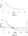
- the general operating principle of the scintillator detector is that: energetic particles are converted into visible light by a scintillation crystal, and then the visible light is converted into an electrical pulse signal by a photodetector.
- a typical electrical pulse signal is shown in Figure 1 .
- the electrical pulse signal may be further processed to acquire information of the energetic particles, such as energy and time information.
- the acquiring time information where the electrical pulse passes over a threshold is widely applied in the field.
- the time information of the energetic particle is acquired by detecting a time point when the electrical pulse passes over a preset threshold.
- a multi-threshold sampling device in the conventional technology is used to implement electrical pulse digitization by acquiring the time information where the electrical pulse passes over multiple thresholds, so as to solve the technical issue of insufficient sampling rate and high power consumption of the traditional analog-to-digital converter (hereinafter abbreviated to ADC) while digitizing such electrical pulses.
- ADC analog-to-digital converter
- the detection of the time points when the electrical pulse passes over the threshold is implemented by combining a comparator with a time-to-digit converter.
- the comparator is configured to compare the electrical pulse with the threshold and output high-level signals or low-level signals based on the comparison result.
- the time point when the electrical pulse passes over the threshold corresponds to a transition between a high level and a low level in the outputted signals of the comparator, and the time point for the transition may be captured with the time-to-digit converter.
- multiple transitions may occur in the outputted signals of the comparator during a time period where the electrical pulse passes over the threshold due to noises in the electrical pulse.
- a method for acquiring a time point when a scintillation pulse passes over a threshold which includes steps of:
- the level signals in the five phases of the positive-going scintillation pulse respectively have characteristics of: the level signal being a constant low-level signal in the phase where the scintillation pulse is lower than the set threshold; the level signal transiting from a low level to a high level, subsequently repeatedly transiting between a high level and a low level and finally becoming a high level in the phase where the scintillation pulse passes over and is higher than the set threshold; the level signal being a constant high-level signal in the phase where the scintillation pulse is higher than the set threshold; the level signal transiting from a high level to a low level, subsequently repeatedly transiting between a high level and a low level and finally becoming a low level in the phase where the scintillation pulse passes over and is lower than the set threshold
- the level signals in the five phases of the negative-going scintillation pulse respectively have characteristics of: the level signal being a constant high-level signal in the phase where the scintillation pulse is higher than the set threshold; the level signal transiting from a high level to a low level, subsequently repeatedly transiting between a high level and a low level and finally becoming a low level in the phase where the scintillation pulse passes over and is lower than the set threshold; the level signal being a constant low-level signal in the phase where the scintillation pulse is lower than the set threshold; the level signal transiting from a low level to a high level, subsequently repeatedly transiting between a high level and a low level and finally becoming a high level in the phase where the scintillation pulse passes over and is higher than the set threshold; the level signal being a constant high-level signal in the phase where the scintillation pulse is higher than the set threshold.
- a median value point of the N time points and/or a weighted value of at least a set of time points for transitions from a low level to a high level may be recorded as the time point when the scintillation pulse passes over the set threshold during the phase where the scintillation pulse passes over and is higher than the set threshold, and a median value point of the M time points and/or a weighted value of at least a set of time points for transitions from a high level to a low level may be recorded as the time point when the scintillation pulse passes over the set threshold during the phase where the scintillation pulse passes over and is lower than the set threshold, in the case that the scintillation pulse is the positive-going scintillation pulse; a median value point of the P time points and/or a weighted value of at least a set of time points for transitions from a
- a weighted value of the time point for the first transition from a low level to a high level and the time point for the last transition from a low level to a high level may be recorded as the time point when the scintillation pulse passes over the set threshold during the phase where the scintillation pulse passes over and is higher than the set threshold, and a weighted value of the time point for the first transition from a high level to a low level and the time point for the last transition from a high level to a low level may be recorded as the time point when the scintillation pulse passes over the set threshold during the phase where the scintillation pulse passes over and is lower than the set threshold, in the case that the scintillation pulse is the positive-going scintillation pulse; and a weighted value of the time point for the first transition from a high level to a low level and the time point for the last
- a weighted value of the time point for the second transition from a low level to a high level and the time point for the second-to-last transition from a low level to a high level may be recorded as the time point when the scintillation pulse passes over the set threshold during the phase where the scintillation pulse passes over and is higher than the set threshold, and a weighted value of the time point for the second transition from a high level to a low level and the time point for the second-to-last transition from a high level to a low level may be recorded as the time point when the scintillation pulse passes over the set threshold during the phase where the scintillation pulse passes over and is lower than the set threshold, in the case that the scintillation pulse is the positive-going scintillation pulse; and a weighted value of the time point for the second transition from a high level to a low
- a weighed value of the N time points may be recorded as the time point when the scintillation pulse passes over the set threshold during the phase where the scintillation pulse passes over and is higher than the set threshold, and a weighed value of the M time points may be recorded as the time point when the scintillation pulse passes over the set threshold during the phase where the scintillation pulse passes over and is lower than the set threshold, in the case that the scintillation pulse is the positive-going scintillation pulse; and a weighed value of the P time points may be recorded as the time point when the scintillation pulse passes over the set threshold during the phase where the scintillation pulse passes over and is lower than the set threshold, and a weighed value of the S time points may be recorded as the time point when the scintillation pulse passes over the set threshold during the phase where the scintillation pulse passes over
- the median value point of the N time points may be recorded as the time point when the scintillation pulse passes over the set threshold during the phase where the scintillation pulse passes over and is higher than the set threshold
- the median value point of the M time points may be recorded as the time point when the scintillation pulse passes over the set threshold during the phase where the scintillation pulse passes over and is lower than the set threshold, in the case that the scintillation pulse is the positive-going scintillation pulse
- the median value point of the P time points may be recorded as the time point when the scintillation pulse passes over the set threshold during the phase where the scintillation pulse passes over and is lower than the set threshold
- the median value point of the S time points may be recorded as the time point when the scintillation pulse passes over the set threshold during the phase where the scintillation pulse passes over and is higher than
- a device for acquiring a time point when scintillation pulse passes over a threshold which includes:
- the delay elements in the delay chain may be configured to receive a signal transmitted by a previous cascaded delay element, output an inverse signal of which a state is opposite to that of the received signal, and transmit the inverse signal to a next cascaded delay element after a time interval dt.
- a frequency of the uniform-frequency square wave signal of the scintillation pulse state time code recording unit may be in a range from 10 MHz to 20 GHz.
- the output signals of the delay chain are sorted by the time code sorting unit into five types of sequences, where a positive-going scintillation pulse is segmented into five phases: a phase where the scintillation pulse is lower than the set threshold, a phase where the scintillation pulse passes over and is higher than the set threshold, a phase where the scintillation pulse is higher than the set threshold, a phase where the scintillation pulse passes over and is lower than the set threshold and a phase where the scintillation pulse is lower than the set threshold, of which the five phases occur sequentially, a negative-going scintillation pulse is segmented into five phases: a phase where the scintillation pulse is higher than the set threshold, a phase where the scintillation pulse passes over and is lower than the set threshold, a phase where the scintillation pulse is lower than the set threshold, a
- the five types of sequences respectively have characteristics of: a sequence consisting of consecutive 1 in the phase where the scintillation pulse is lower than the set threshold; a sequence starting with multiple consecutive s, then switching to 1, subsequently repeatedly switching between 0 and 1, and ending with multiple consecutive 1, from a least significant bit, LSB, to a most significant bit, MSB, in the phase where the scintillation pulse passes over and is higher than the set threshold; a sequence consisting of consecutive 0 in the phase where the scintillation pulse is higher than the set threshold; a sequence starting with multiple consecutive 1, then switching to 0, subsequently repeatedly switching between 0 and 1, and ending with multiple 0, from the LSB to the MSB, in the phase where the scintillation pulse passes over and is lower than the set threshold; and a sequence consisting of consecutive 1 in the phase where the scintillation pulse is lower than the set threshold.
- the five types of sequences respectively have characteristics of: a sequence consisting of consecutive 0 in the phase where the scintillation pulse is higher than the set threshold; a sequence starting with multiple 1, then switching to 0, subsequently repeatedly switching between 0 and 1, and ending with multiple 0 from the LSB to the MSB in the phase where the scintillation pulse passes over and is lower than the set threshold; a sequence consisting of consecutive 1 in the phase where the scintillation pulse is lower than the set threshold; a sequence starting with multiple 0, then switching to 1, subsequently repeatedly switching between 0 and 1 and ending with multiple 1 from the LSB to the MSB in the phase the scintillation pulse passes over and is higher than over and is higher than the set threshold; and a sequence consisting of consecutive 0 in the phase where the scintillation pulse is higher than the set threshold.
- the relative time interpretation unit may be configured to count the number of delay elements until a first 1 occurs from the LSB to the MSB to indicate a time period required for the first transition from a low level to a high level, and the number of delay elements until a last 0 occurs from the LSB to the MSB to indicate a time period required for the last transition from a low level to a high level during the phase where the scintillation pulse passes over and is higher than the set threshold; and to count the number of delay elements until a last 1 occurs from the LSB to the MSB to indicate a time period required for the first transition from a high level to a low level, and the number of delay elements until a first 0 occurs from the LSB to the MSB to indicate a time period required for the last transition from a high level to a low level during the phase where the scintillation pulse passes over and is lower than the set threshold,
- a more accurate time point when the scintillation pulse passes over the threshold may be acquired by selecting one of the time points for transitions or weighting two or more of the time points for transitions.
- a more accurate time point when the scintillation pulse actually passes over the threshold may be acquired by acquiring a time point when a first transition occurs and a time point when a last transition occurs during the time period where the scintillation pulse passes over the threshold and weighting the two time points.
- the time point for the first transition, the time point for the last transition and any of the time points for transitions between the first transition and the last transition may be acquired by analyzing the outputted signals of the delay chain to acquire time points when transitions from 0 to 1 or 1 to 0 occur and relationships between the time points.
- a method and a device for acquiring a time point when a scintillation pulse passes over a threshold are provided according to the disclosure, so as to solve the issue that the time point can not be acquired accurately due to noises.
- Both a positive-going pulse signal and a negative-going pulse signal are described in the disclosure since the scintillation pulse signal may be the positive-going or negative-going pulse signal.
- the method for acquiring a time point when a scintillation pulse passes over a threshold includes the following steps (1) to (3).
- step (1) a relationship between the scintillation pulse and a set threshold is converted by a comparator into a level signal, where high-level signals are outputted in a case that the amplitude of the scintillation pulse is higher than the set threshold, or low-level signals are outputted in a case that the amplitude of the scintillation pulse is lower than the set threshold.
- step (2) the outputted level signals are segmented, where a positive-going scintillation pulse is segmented into five phases: a phase where the scintillation pulse is lower than the set threshold, a phase where the scintillation pulse passes over and is higher than the set threshold, a phase where the scintillation pulse is higher than the set threshold, a phase where the scintillation pulse passes over and is lower than the set threshold and a phase where the scintillation pulse is lower than the set threshold, of which the five phases occur sequentially, a negative-going scintillation pulse is segmented into five phases: a phase where the scintillation pulse is higher than the set threshold, a phase where the scintillation pulse passes over and is lower than the set threshold, a phase where the scintillation pulse is lower than the set threshold, a phase where the scintillation pulse passes over and is higher than the set threshold and a phase where the scintillation pulse is higher than the set threshold, of
- the outputted level signals in the five phases of the positive-going scintillation pulse respectively have characteristics of: the level signal being a constant low-level signal in the phase where the scintillation pulse is lower than the set threshold; the level signal transiting from a low level to a high level, subsequently repeatedly transiting between a high level and a low level and finally becoming a high level in the phase where the scintillation pulse passes over and is higher than the set threshold; the level signal being a constant high-level signal in the phase where the scintillation pulse is higher than the set threshold; the level signal transiting from a high level to a low level; subsequently repeatedly transiting between a high level and a low level and finally becoming a low level in the phase where the scintillation pulse passes over and is lower than the set threshold; and the level signal being a constant low-level signal in the phase where the scintillation pulse is lower than the set threshold.
- the outputted level signals in the five phases of the negative-going scintillation pulse respectively have characteristics of: the level signal being a constant high-level signal in the phase where the scintillation pulse is higher than the set threshold; the level signal transiting from a high level to a low level, subsequently repeatedly transiting between a high level and a low level and finally becoming a low level in the phase where the scintillation pulse passes over and is lower than the set threshold; the level signal being a constant low-level signal in the phase where the scintillation pulse is lower than the set threshold; the level signal transiting from a low level to a high level, subsequently repeatedly transiting between a high level and a low level and finally becoming a high level in the phase where the scintillation pulse passes over and is higher than the set threshold; and the level signal being a constant high-level signal in the phase where the scintillation pulse is higher than the set threshold.
- step (3) the time point when the scintillation pulse passes over the set threshold is recorded, during the phase where the scintillation pulse passes over and is higher than the set threshold, and during the phase where the scintillation pulse passes over and is lower than the set threshold; where, in a case that the scintillation pulse is the positive-going scintillation pulse or the negative-going scintillation pulse, during the phase where the scintillation pulse is lower than the set threshold and the phase where the scintillation pulse is higher than the set threshold, no time point when the scintillation pulse passes over the set threshold is recorded and the comparator outputs constant high-level signals or constant low-level signals; during the phase where the scintillation pulse passes over and is higher than the set threshold, N transitions may occur at N time points, and any one of the N time points, or a median value or a weighted value of any two or more of the N time points is recorded as the time point when the scintillation pulse passes over the set threshold
- the scintillation pulse is the negative-going scintillation pulse
- P transitions may occur at P time points, and any one of the P time points, or a median value or a weighted value of any two or more of the P time points is recorded as the time point when the scintillation pulse passes over the set threshold
- S transitions may occur at S time points, and any one of the S time points, or a median value or a weighted value of any two or more of the S time points is recorded as the time point when the scintillation pulse passes over the set threshold.
- the weighted value or the median value point of some (one, two or n continuous or non-continuous time points of the N (M, P, or S) time points which are sampled regularly or irregularly) or all of N (M, P, or S) time points may be used to indicate an accurate time point.
- step (3) includes: a median value point of the N time points and/or a weighted value of at least a set of time points for transitions from a low level to a high level is recorded as the time point when the scintillation pulse passes over the set threshold during the phase where the scintillation pulse passes over and is higher than the set threshold, and a median value point of the M time points and/or a weighted value of at least a set of time points for transitions from a high level to a low level is recorded as the time point when the scintillation pulse passes over the set threshold during the phase where the scintillation pulse passes over and is lower than the set threshold, in the case that the scintillation pulse is the positive-going scintillation pulse; and a median value point of the P time points and/or a weighted value of at least a set of time points for transitions from a high level to a low level is recorded as the time point when the scintillation pulse
- a first further preferable scope of the disclosure regarding step (3) includes: a weighted value of the time point for the first transition from a low level to a high level and the time point for the last transition from a low level to a high level is recorded as the time point when the scintillation pulse passes over the set threshold during the phase where the scintillation pulse passes over and is higher than the set threshold, and a weighted value of the time point for the first transition from a high level to a low level and the time point for the last transition from a high level to a low level is recorded as the time point when the scintillation pulse passes over the set threshold during the phase where the scintillation pulse passes over and is lower than the set threshold, in the case that the scintillation pulse is the positive-going scintillation pulse; and a weighted value of the time point for the first transition from a high level to a low level and the time point for the last transition from a high level to a low level is recorded as the time point when the sci
- a second further preferable scope of the disclosure regarding step (3) includes: a weighted value of the time point for the second transition from a low level to a high level and the time point for the second-to-last transition from a low level to a high level is recorded as the time point when the scintillation pulse passes over the set threshold during the phase where the scintillation pulse passes over and is higher than the set threshold, and a weighted value of the time point for the second transition from a high level to a low level and the time point for the second-to-last transition from a high level to a low level is recorded as the time point when the scintillation pulse passes over the set threshold during the phase where the scintillation pulse passes over and is lower than the set threshold, in the case that the scintillation pulse is the positive-going scintillation pulse; and a weighted value of the time point for the second transition from a high level to a low level and the time point for the second-to-last transition from a high level to
- a third further preferable scope of the disclosure regarding step (3) includes: a weighed value of the N time points is recorded as the time point when the scintillation pulse passes over the set threshold during the phase where the scintillation pulse passes over and is higher than the set threshold, and a weighed value of the M time points is recorded as the time point when the scintillation pulse passes over the set threshold during the phase where the scintillation pulse passes over and is lower than the set threshold, in the case that the scintillation pulse is the positive-going scintillation pulse; and a weighed value of the P time points is recorded as the time point when the scintillation pulse passes over the set threshold during the phase where the scintillation pulse passes over and is lower than the set threshold, and a weighed value of the S time points is recorded as the time point when the scintillation pulse passes over the set threshold during the phase where the scintillation pulse passes over and is higher than the set threshold, in the case that the scintillation pulse is the negative
- a fourth further preferable scope of the disclosure regarding step (3) includes: the median value point of the N time points is recorded as the time point when the scintillation pulse passes over the set threshold during the phase where the scintillation pulse passes over and is higher than the set threshold, and the median value point of the M time points is recorded as the time point when the scintillation pulse passes over the set threshold during the phase where the scintillation pulse passes over and is lower than the set threshold, in a case that the scintillation pulse is the positive-going scintillation pulse; and the median value point of the P time points is recorded as the time point when the scintillation pulse passes over the set threshold during the phase where the scintillation pulse passes over and is lower than the set threshold, and the median value point of the S time points is recorded as the time point when the scintillation pulse passes over the set threshold during the phase where the scintillation pulse passes over and is higher than the set threshold, in the case that the scintillation pulse is the negative-going sci
- the above median value point indicates the time point when a middle transition occurs. For example, given that the number of transitions M is equal to 8, the median value point is an average value of the time point for a fourth transition and the time point for a fifth transition. As another example, given that the number of transitions M is equal to 7, the median value point is the time point for a fourth transition.
- the median value point for N transitions may be calculated in the same way.
- the time point when the scintillation pulse passes over the set threshold may be acquired by weighting the time point for the first transition and the time point for the last transition, or may be acquired by weighting the time point for the second transition and the time point for the second-to-last transition and the like.
- the time point when the scintillation pulse passes over the set threshold may be acquired by acquiring all of the time points for transitions during the phases where the scintillation pulse passes over the set threshold and weighing all of the time points, may be acquired by acquiring the median value point of all of the time points, or even may be acquired through a likelihood estimation approach.
- the time point for the first transition, the time point for the last transition and all of time points for the transitions between the first transition and the last transition are acquired by analyzing the outputted signals of the delay chain to acquire time points when transitions from 0 to 1 or 1 to 0 occur and relationships between the time points.
- a device for acquiring a time point when a scintillation pulse passes over a threshold includes a comparison unit, a delay chain, a scintillation pulse state time code recording unit, a time code sorting unit, a relative time interpretation unit and a time calculation and transmission unit.
- the comparison unit is configured to output level signals based on a relationship between the scintillation pulse and a set threshold, where high-level signals are outputted in a case that an amplitude of the scintillation pulse is higher than the set threshold, or low-level signals are outputted in a case that the amplitude of the scintillation pulse is lower than the set threshold.
- the delay chain is composed of several cascaded delay elements and configured to receive and output the high-level signals and the low-level signals.
- the delay elements in the delay chain is configured to receive a signal transmitted by a previous cascaded delay element, output an inverse signal of which a state is opposite to that of the received signal, and transmit the inverse signal to a next cascaded delay element after a time interval dt.
- the scintillation pulse state time code recording unit includes an uniform-frequency square wave signal, a counter, and a data buffer unit, where the counter is configured to record the number of rising edges of the square wave, the data buffer unit is configured to record output signals of the delay elements in the delay chain at a time instant when the rising edge of the square wave is arrived, the output signals of the delay chain and the number of rising edges of the square wave are combined into a time code.
- a frequency of the uniform-frequency square wave signal of the scintillation pulse state time code recording unit is in a range from 10 MHz to 20 GHz.
- the counter is configured to record the number of rising edges of the square wave
- the data buffer unit is configured to record output signals of the delay elements in the delay chain at a time instant when the rising edge of the square wave is arrived, the output signals of the delay chain and the number of rising edges of the square wave are combined into a time code.
- the time code sorting unit is configured to sort the output signals of the delay chain according to a characteristic of the recorded output signals of the delay chain.
- Output signals of the delay chain may be sorted by the time code sorting unit into five types of sequences, where a positive-going scintillation pulse is segmented into five phases: a phase where the scintillation pulse is lower than the set threshold, a phase where the scintillation pulse passes over and is higher than the set threshold, a phase where the scintillation pulse is higher than the set threshold, a phase where the scintillation pulse passes over and is lower than the set threshold and a phase where the scintillation pulse is lower than the set threshold, of which the five phases occur sequentially, a negative-going scintillation pulse is segmented into five phases: a phase where the scintillation pulse is higher than the set threshold, a phase where the scintillation pulse passes over and is lower than the set threshold, a phase where the scintillation pulse is
- the five types of sequences respectively have characteristics of: a sequence consisting of consecutive 1 in the phase where the scintillation pulse is lower than the set threshold; a sequence starting with multiple consecutive 0, then switching to 1, subsequently repeatedly switching between 0 and 1, and ending with multiple consecutive 1, from a least significant bit, LSB, to a most significant bit, MSB, in the phase where the scintillation pulse passes over and is higher than the set threshold; a sequence consisting of consecutive 0 in the phase where the scintillation pulse is higher than the set threshold; a sequence starting with multiple consecutive 1, then switching to 0, subsequently repeatedly switching between 0 and 1, and ending with multiple 0 from the LSB to the MSB in the phase where the scintillation pulse passes over and is lower than the set threshold; and a sequence consisting of consecutive 1 in the phase where the scintillation pulse is lower than the set threshold.
- the five types of sequences respectively have characteristics of: a sequence consisting of consecutive 0 in the phase where the scintillation pulse is higher than the set threshold; a sequence starting with multiple 1, then switching to 0, subsequently repeatedly switching between 0 and 1, and ending with multiple 0 from the LSB to the MSB in the phase where the scintillation pulse passes over and is lower than the set threshold; a sequence consisting of consecutive 1 in the phase where the scintillation pulse is lower than the set threshold; a sequence starting with multiple 0, then switching to 1, subsequently repeatedly switching between 0 and 1, and ending with multiple 1 from the LSB to the MSB in the phase the scintillation pulse passes over and is higher than the set threshold; and a sequence consisting of consecutive 0 in the phase where the scintillation pulse is higher than the set threshold.
- the relative time interpretation unit is configured to interpret a time interval between a transition of the scintillation pulse and a subsequent rising edge of the square wave.
- the relative time interpretation unit is configured to count the number of delay elements until a first 1 occurs from the LSB to the MSB to indicate a time period required for the first transition from a low level to a high level, and the number of delay elements until a last 0 occurs from the LSB to the MSB to indicate a time period required for the last transition from a low level to a high level during the phase where the scintillation pulse passes over and is higher than the set threshold; and to count the number of delay elements until a last 1 occurs from the LSB to the MSB to indicate a time period required for the first transition from a high level to a low level, and the number of delay elements until a first 0 occurs from the LSB to the MSB to indicate a time period required for the last transition from a high level to a low level during the phase where the scintillation pulse passes over and is lower than the set threshold, in the case that the scintillation pulse is the positive-going scintillation pulse.
- the relative time interpretation unit is configured to count the number of delay elements until a first 0 occurs from the LSB to the MSB to indicate a time period required for the first transition from a high level to a low level, and the number of delay elements until a last 1 occurs from the LSB to the MSB to indicate a time period required for the last transition from a high level to a low level during the phase where the scintillation pulse passes over and is lower than the set threshold; and to count the number of delay elements until a last 0 occurs from the LSB to the MSB to indicate a time period required for the first transition from a low level to a high level, and the number of delay elements until a first 1 occurs from the LSB to the MSB to indicate a time period required for the last transition from a low level to a high level during the phase where the scintillation pulse passes over and is higher than the set threshold, in the case that the scintillation pulse is the negative-going scintillation pulse.
- the time calculation and transmission unit is configured to calculate time points for transitions according to time information acquired by the relative time interpretation unit, acquire an accurate time point when the scintillation pulse passes over the set threshold by selecting one of the time points or weighting any two or more of the time points and transmit the accurate time point to a next unit.
- Figure 3 is a schematic diagram of logical output signals outputted by a comparator in which the scintillation pulse is inputted and states of the signals outputted by the delay chain from a least significant bit (LSB) to a most significant bit (MSB).
- LSB least significant bit
- MSB most significant bit
- a rising edge of the scintillation pulse is not affected by noises, and thus the state of the logic signal transits only once until being maintained at a logic high level stably during the phase where the scintillation pulse passes over and is higher than the threshold; a falling edge of the scintillation pulse is affected by noises, and thus the state of the logic output signal transits once and switches for multiple times until being maintained at a logic low level during the phase where the scintillation pulse passes over and is lower than the threshold.
- A, B and C shown in Figure 3 represent a rising edge of the logic output signal when the pulse passes over and is higher than the threshold, a first falling edge of the logic output signal and a final falling edge of the logic output signal when the pulse passes over and is lower than the threshold respectively.
- the logic output signal is inputted into a delay chain.
- Output signals outputted by the delay chain at different rising edges of a clock signal are shown in the left side of Figure 3 .
- three delay chains are used in this example to record time points when A, B and C occurs respectively, and three different encoding modes are used for the three delay chains.
- the delay chain for capturing the time point when A occurs consists of m cascading adders, where an augend of the adder at each stage is set to 1, and an addend of the adder at each stage is set to 0.
- the output Sum of the adder transits from a high level to a low level, as indicated by A shown in Figure 3 .
- the number N of consecutive 0 outputted by the delay chain from a least significant bit (LSB) to a most significant bit (MSB) is coded using a priority encoder. Given that a delay of the adders is T, a time interval between A and a current rising edge of the clock signal is N*T.
- the carry chain for capturing the time point when B occurs consists of m cascading adders, where an augend of the adder at each stage is set to 1, and an addend of the adder at each stage is set to 0.
- the logic level outputted by the comparator connected to a carry input of a first-stage adder in the carry chain transits a low level to a high level
- the output Sum of the adder transits from a high level to a low level, as indicated by B shown in Figure 3 .
- the number N of consecutive 0 outputted by the delay chain from a most significant bit (MSB) to a least significant bit (LSB) is coded.
- the carry chain for capturing the time point when C occurs consists of m cascading adders, where an augend of the adder at each stage is set to 1, and an addend of the adder at each stage is set to 0.
- the logic level outputted by the comparator connected to a carry input of a first-stage adder in the carry chain transits from a low level to a high level
- the output Sum of the adder transits from a high level to a low level, as indicated by C shown in Figure 3 .
- N The number N of consecutive 1 outputted by the delay chain from a least significant bit (LSB) to a most significant bit (MSB) is coded.
- LSB least significant bit
- MSB most significant bit
- the time points for A, B, and C may be acquired based on the time intervals acquired in the above way in conjunction with the number of cycles of the clock signal recorded by a clock counter.
- Sampled time points acquired at different thresholds with the method according to the disclosure are shown in Figure 4 (Four results acquired at four different thresholds are shown in Figure 4 , and the method according to the disclosure is used to acquire the sampled time points at the different thresholds), where a round spot indicates a actually acquired sampled time point.
- an actual time point when the scintillation pulse passes over the threshold is acquired by weighting two sampled time point acquired in the falling edge of the scintillation pulse. The actual time point is marked with an asterisk, as shown in Figure 4 .
- a method is provided to solve the issue of inaccurate sampling of voltage-time pairs due to noises.
- noises in the falling edge of the scintillation pulse are not considered, and a first transition edge is recorded as the time point when the scintillation pulse passes over the threshold.
- the collected time point is invariably earlier than the actual time point when the scintillation pulse passes over the threshold in the presence of noises, and thus the accuracy of the collection is reduced.
- a method for acquiring time points for all of the transition edges during the phase where the scintillation pulse passes over the threshold is proposed in accordance with the disclosure, and a more accurate time point when the scintillation pulse passes over the threshold are acquired with a weighting process.
- a pulse shape may be restored more accurately by analyzing and processing the acquired time points for N (M, P, or S) transitions, thereby reducing the effect of noises on pulse restoration.
- the time points for the transitions are acquired mainly by analyzing states of signals outputted by the carry chain.
- the time point for the first transition edge and the time point for the last transition edge are acquired, and the actual time point when the scintillation pulse passes over the threshold may be more accurately acquired by weighting the two time points for transition edges.
- the actual time point when the scintillation pulse passes over the threshold may be more accurately acquired by acquiring a median value point of the acquired multiple time points for transition edges and/or by weighting at least a set of time points for transition edges.
- the time point for the first transition, the time point for the last transition and all of the time points for transitions between the first transition and the last transition may be acquired by analyzing the outputted signals of the delay chain to acquire time points when transitions from 0 to 1 or 1 to 0 occur and relationships between the time points.
Landscapes
- Physics & Mathematics (AREA)
- General Physics & Mathematics (AREA)
- Nonlinear Science (AREA)
- Health & Medical Sciences (AREA)
- Life Sciences & Earth Sciences (AREA)
- High Energy & Nuclear Physics (AREA)
- Molecular Biology (AREA)
- Spectroscopy & Molecular Physics (AREA)
- Measurement Of Radiation (AREA)
- Nuclear Medicine (AREA)
Claims (12)
- Procédé permettant d'acquérir un instant auquel une impulsion de scintillement franchit un seuil, comprenant :une conversion d'une relation entre l'impulsion de scintillement et un seuil réglé en signaux de niveau par un comparateur, dans lequel des signaux de haut niveau sont délivrés dans un cas dans lequel une amplitude de l'impulsion de scintillement est supérieure au seuil réglé, ou des signaux de bas niveau sont délivrés dans un cas dans lequel l'amplitude de l'impulsion de scintillement est inférieure au seuil réglé ;une segmentation des signaux de haut niveau ou de bas niveau délivrés, dans lequel une impulsion de scintillement devenant positive est segmentée en cinq phases : une phase dans laquelle l'impulsion de scintillement est inférieure au seuil réglé, une phase dans laquelle l'impulsion de scintillement franchit et est supérieure au seuil réglé, une phase dans laquelle l'impulsion de scintillement est supérieure au seuil réglé, une phase dans laquelle l'impulsion de scintillement franchit et est inférieure au seuil réglé et une phase dans laquelle l'impulsion de scintillement est inférieure au seuil réglé, les cinq phases se déroulant successivement ; une impulsion de scintillement devenant négative est segmentée en cinq phases : une phase dans laquelle l'impulsion de scintillement est supérieure au seuil réglé, une phase dans laquelle l'impulsion de scintillement franchit et est inférieure au seuil réglé, une phase dans laquelle l'impulsion de scintillement est inférieure au seuil réglé, une phase dans laquelle l'impulsion de scintillement franchit et est supérieure au seuil réglé et une phase dans laquelle l'impulsion de scintillement est supérieure au seuil réglé, les cinq phases se déroulant successivement ; etun enregistrement de l'instant auquel l'impulsion de scintillement franchit le seuil réglé, pendant la phase au cours de laquelle l'impulsion de scintillement franchit et est supérieure au seuil réglé, et pendant la phase au cours de laquelle l'impulsion de scintillement franchit et est inférieure au seuil réglé,dans lequel, dans un cas dans lequel l'impulsion de scintillement est l'impulsion de scintillement devenant positive ou l'impulsion de scintillement devenant négative, pendant la phase au cours de laquelle l'impulsion de scintillement est inférieure au seuil réglé et la phase au cours de laquelle l'impulsion de scintillement est supérieure au seuil réglé, aucun instant auquel l'impulsion de scintillement franchit le seuil réglé n'est enregistré et le comparateur délivre des signaux de haut niveau constants ou des signaux de bas niveau constants ;pendant la phase au cours de laquelle l'impulsion de scintillement franchit et est supérieure au seuil réglé, N transitions surviennent à N instants, l'un des N instants, ou une valeur médiane ou une valeur pondérée d'au moins deux quelconques des N instants est enregistré en tant que l'instant auquel l'impulsion de scintillement franchit le seuil réglé ; pendant la phase au cours de laquelle l'impulsion de scintillement franchit et est inférieure au seuil réglé, M transitions surviennent à M instants, l'un quelconque des M instants, ou une valeur médiane ou une valeur pondérée d'au moins deux quelconques des M instants est enregistré en tant que l'instant auquel l'impulsion de scintillement franchit le seuil réglé, dans un cas dans lequel l'impulsion de scintillement est l'impulsion de scintillement devenant positive ; etpendant la phase au cours de laquelle l'impulsion de scintillement franchit et est inférieure au seuil réglé, P transitions surviennent à P instants, l'un quelconque des P instants, ou une valeur médiane ou une valeur pondérée d'au moins deux quelconques des P instants est enregistré en tant que l'instant auquel l'impulsion de scintillement franchit le seuil réglé ; et pendant la phase au cours de laquelle l'impulsion de scintillement franchit et est supérieure au seuil réglé, S transitions surviennent à S instants, l'un quelconque des S instants, ou une valeur médiane ou une valeur pondérée d'au moins deux quelconques des S instants est enregistré en tant que l'instant auquel l'impulsion de scintillement franchit le seuil réglé, dans un cas dans lequel l'impulsion de scintillement est l'impulsion de scintillement devenant négative.
- Procédé permettant d'acquérir un instant auquel une impulsion de scintillement franchit un seuil selon la revendication 1, dans lequel, dans le cas dans lequel l'impulsion de scintillement est l'impulsion de scintillement devenant positive, les signaux de niveau dans les cinq phases de l'impulsion de scintillement devenant positive ont respectivement les caractéristiques suivantes : le signal de niveau est un signal de bas niveau constant ; le signal de niveau est en transition d'un bas niveau à un haut niveau, puis en transition à répétition entre un haut niveau et un bas niveau, et enfin devient un haut niveau ; le signal de niveau est un signal de haut niveau constant ; le signal de niveau est en transition d'un haut niveau à un bas niveau, puis en transition à répétition entre un haut niveau et un bas niveau, et enfin devient un bas niveau ; et le signal de niveau est un signal de bas niveau constant ; et
dans le cas dans lequel l'impulsion de scintillement est l'impulsion de scintillement devenant négative, les signaux de niveau dans les cinq phases de l'impulsion de scintillement devenant négative ont respectivement les caractéristiques suivantes : le signal de niveau est un signal de haut niveau constant ; le signal de niveau est en transition d'un haut niveau à un bas niveau, puis en transition à répétition entre un haut niveau et un bas niveau, et enfin devient un bas niveau ; le signal de niveau est un signal de bas niveau constant ; le signal de niveau est en transition d'un bas niveau à un haut niveau, puis en transition à répétition entre un haut niveau et un bas niveau, et enfin devient un haut niveau ; et le signal de niveau est un signal de haut niveau constant. - Procédé permettant d'acquérir un instant auquel une impulsion de scintillement franchit un seuil selon la revendication 1 ou 2, dans lequel une valeur médiane des N instants et/ou une valeur pondérée d'au moins un ensemble d'instants pour des transitions d'un bas niveau à un haut niveau sont enregistrées en tant que l'instant auquel l'impulsion de scintillement franchit le seuil réglé pendant la phase au cours de laquelle l'impulsion de scintillement franchit et est supérieure au seuil réglé, et une valeur médiane des M instants et/ou une valeur pondérée d'au moins un ensemble d'instants pour des transitions d'un haut niveau à un bas niveau est enregistrée en tant que l'instant auquel l'impulsion de scintillement franchit le seuil réglé pendant la phase au cours de laquelle l'impulsion de scintillement franchit et est inférieure au seuil réglé, dans le cas dans lequel l'impulsion de scintillement est l'impulsion de scintillement devenant positive ; et
une valeur médiane des P instants et/ou une valeur pondérée d'au moins un ensemble d'instants pour des transitions d'un haut niveau à un bas niveau est enregistrée en tant que l'instant auquel l'impulsion de scintillement franchit le seuil réglé pendant la phase au cours de laquelle l'impulsion de scintillement franchit et est inférieure au seuil réglé, et une valeur médiane des S instants et/ou une valeur pondérée d'au moins un ensemble d'instants pour des transitions d'un bas niveau à un haut niveau est enregistrée en tant que l'instant auquel l'impulsion de scintillement franchit le seuil réglé pendant la phase au cours de laquelle l'impulsion de scintillement franchit et est supérieure au seuil réglé, dans le cas dans lequel l'impulsion de scintillement est l'impulsion de scintillement devenant négative,
dans lequel un instant pour une première transition d'un bas niveau à un haut niveau et un instant pour une dernière transition d'un bas niveau à un haut niveau sont regroupés dans un groupe, un instant pour une deuxième transition d'un bas niveau à un haut niveau et un instant pour une avant-dernière transition d'un bas niveau à un haut niveau sont regroupés dans un groupe, et deux instants acquis par analogie sont regroupés dans un groupe ; un instant pour une première transition d'un haut niveau à un bas niveau et un instant pour une dernière transition d'un haut niveau à un bas niveau sont regroupés dans un groupe, un instant pour une deuxième transition d'un haut niveau à un bas niveau et un instant pour une avant-dernière transition d'un haut niveau à un bas niveau sont regroupés dans un groupe, et deux instants acquis par analogie sont regroupés dans un groupe. - Procédé permettant d'acquérir un instant auquel une impulsion de scintillement franchit un seuil selon la revendication 3, dans lequel une valeur pondérée de l'instant pour la première transition d'un bas niveau à un haut niveau et de l'instant pour la dernière transition d'un bas niveau à un haut niveau est enregistrée en tant que l'instant auquel l'impulsion de scintillement franchit le seuil réglé pendant la phase au cours de laquelle l'impulsion de scintillement franchit et est supérieure au seuil réglé, et une valeur pondérée de l'instant pour la première transition d'un haut niveau à un bas niveau et de l'instant pour la dernière transition d'un haut niveau à un bas niveau est enregistrée en tant que l'instant auquel l'impulsion de scintillement franchit le seuil réglé pendant la phase au cours de laquelle l'impulsion de scintillement franchit et est inférieure au seuil réglé, dans le cas dans lequel l'impulsion de scintillement est l'impulsion de scintillement devenant positive ; et
une valeur pondérée de l'instant pour la première transition d'un haut niveau à un bas niveau et de l'instant pour la dernière transition d'un haut niveau à un bas niveau est enregistrée en tant que l'instant auquel l'impulsion de scintillement franchit le seuil réglé pendant la phase au cours de laquelle l'impulsion de scintillement franchit et est inférieure au seuil réglé, et une valeur pondérée de l'instant pour la première transition d'un bas niveau à un haut niveau et de l'instant pour la dernière transition d'un bas niveau à un haut niveau est enregistrée en tant que l'instant auquel l'impulsion de scintillement franchit le seuil réglé pendant la phase au cours de laquelle l'impulsion de scintillement franchit et est supérieure au seuil réglé, dans le cas dans lequel l'impulsion de scintillement est l'impulsion de scintillement devenant négative. - Procédé permettant d'acquérir un instant auquel une impulsion de scintillement franchit un seuil selon la revendication 3, dans lequel une valeur pondérée de l'instant pour la deuxième transition d'un bas niveau à un haut niveau et de l'instant pour l'avant-dernière transition d'un bas niveau à un haut niveau est enregistrée en tant que l'instant auquel l'impulsion de scintillement franchit le seuil réglé pendant la phase au cours de laquelle l'impulsion de scintillement franchit et est supérieure au seuil réglé, et une valeur pondérée de l'instant pour la deuxième transition d'un haut niveau à un bas niveau et de l'instant pour l'avant-dernière transition d'un haut niveau à un bas niveau est enregistrée en tant que l'instant auquel l'impulsion de scintillement franchit le seuil réglé pendant la phase au cours de laquelle l'impulsion de scintillement franchit et est inférieure au seuil réglé, dans le cas dans lequel l'impulsion de scintillement est l'impulsion de scintillement devenant positive ; et
une valeur pondérée de l'instant pour la deuxième transition d'un haut niveau à un bas niveau et de l'instant pour l'avant-dernière transition d'un haut niveau à un bas niveau est enregistrée en tant que l'instant auquel l'impulsion de scintillement franchit le seuil réglé pendant la phase au cours de laquelle l'impulsion de scintillement franchit et est inférieure au seuil réglé, et une valeur pondérée de l'instant pour la deuxième transition d'un bas niveau à un haut niveau et de l'instant pour l'avant-dernière transition d'un bas niveau à un haut niveau est enregistrée en tant que l'instant auquel l'impulsion de scintillement franchit le seuil réglé pendant la phase au cours de laquelle l'impulsion de scintillement franchit et est supérieure au seuil réglé, dans le cas dans lequel l'impulsion de scintillement est l'impulsion de scintillement devenant négative. - Procédé permettant d'acquérir un instant auquel une impulsion de scintillement franchit un seuil selon la revendication 3, dans lequel une valeur pondérée des N instants est enregistrée en tant que l'instant auquel l'impulsion de scintillement franchit le seuil réglé pendant la phase au cours de laquelle l'impulsion de scintillement franchit et est supérieure au seuil réglé, et une valeur pondérée des M instants est enregistrée en tant que l'instant auquel l'impulsion de scintillement franchit le seuil réglé pendant la phase au cours de laquelle l'impulsion de scintillement franchit et est inférieure au seuil réglé, dans le cas dans lequel l'impulsion de scintillement est l'impulsion de scintillement devenant positive ; et
une valeur pondérée des P instants est enregistrée en tant que l'instant auquel l'impulsion de scintillement franchit le seuil réglé pendant la phase au cours de laquelle l'impulsion de scintillement franchit et est inférieure au seuil réglé, et une valeur pondérée des S instants est enregistrée en tant que l'instant auquel l'impulsion de scintillement franchit le seuil réglé pendant la phase au cours de laquelle l'impulsion de scintillement franchit et est supérieure au seuil réglé, dans le cas dans lequel l'impulsion de scintillement est l'impulsion de scintillement devenant négative. - Procédé permettant d'acquérir un instant auquel une impulsion de scintillement franchit un seuil selon la revendication 3, dans lequel la valeur médiane des N instants est enregistrée en tant que l'instant auquel l'impulsion de scintillement franchit le seuil réglé pendant la phase au cours de laquelle l'impulsion de scintillement franchit et est supérieure au seuil réglé, et la valeur médiane des M instants est enregistrée en tant que l'instant auquel l'impulsion de scintillement franchit le seuil réglé pendant la phase au cours de laquelle l'impulsion de scintillement franchit et est inférieure au seuil réglé, dans le cas dans lequel l'impulsion de scintillement est l'impulsion de scintillement devenant positive ; et
la valeur médiane des P instants est enregistrée en tant que l'instant auquel l'impulsion de scintillement franchit le seuil réglé pendant la phase au cours de laquelle l'impulsion de scintillement franchit et est inférieure au seuil réglé, et la valeur médiane des S instants est enregistrée en tant que l'instant auquel l'impulsion de scintillement franchit le seuil réglé pendant la phase au cours de laquelle l'impulsion de scintillement franchit et est supérieure au seuil réglé, dans le cas dans lequel l'impulsion de scintillement est l'impulsion de scintillement devenant négative. - Dispositif permettant d'acquérir un instant auquel une impulsion de scintillement franchit un seuil, comprenant :une unité de comparaison configurée pour délivrer des signaux de niveau sur la base d'une relation entre l'impulsion de scintillement et un seuil réglé, dans lequel des signaux de haut niveau sont délivrés dans un cas dans lequel une amplitude de l'impulsion de scintillement est supérieure au seuil réglé, ou des signaux de bas niveau sont délivrés dans un cas dans lequel l'amplitude de l'impulsion de scintillement est inférieure au seuil réglé ;une chaîne de retard composée de plusieurs éléments de retard en cascade et configurée pour recevoir et délivrer les signaux de haut niveau et les signaux de bas niveau ;une unité d'enregistrement de code de temps d'état d'impulsion de scintillement comprenant un signal d'onde carrée de fréquence uniforme, un compteur, et une unité de mémoire tampon de données, dans lequel le compteur est configuré pour enregistrer le nombre de fronts montants de l'onde carrée, l'unité de mémoire tampon de données est configurée pour enregistrer des signaux de sortie des éléments de retard dans la chaîne de retard à un instant auquel le front montant de l'onde carrée est arrivé, les signaux de sortie de la chaîne de retard et le nombre de fronts montants de l'onde carrée sont combinés dans un code de temps ;une unité de tri de code de temps configurée pour trier les signaux de sortie de la chaîne de retard en fonction d'une caractéristique des signaux de sortie enregistrés de la chaîne de retard ;une unité d'interprétation de temps relatif configurée pour interpréter un intervalle de temps entre une transition de l'impulsion de scintillement et un front montant suivant de l'onde carrée ;une unité de calcul et de transmission de temps configurée pour calculer des instants pour des transitions en fonction d'informations de temps acquises par l'unité d'interprétation de temps relatif, acquérir un instant précis auquel l'impulsion de scintillement franchit le seuil réglé par la sélection de l'un des instants ou par la pondération d'au moins deux quelconques des instants, et transmettre l'instant précis à une unité suivante.
- Dispositif permettant d'acquérir un instant auquel une impulsion de scintillement franchit un seuil selon la revendication 8, dans lequel les éléments de retard dans la chaîne de retard sont configurés pour recevoir un signal transmis par un élément de retard en cascade précédent, délivrer un signal inverse dont un état est opposé à celui du signal reçu, et transmettre le signal inverse à un élément de retard en cascade suivant après un intervalle de temps dt.
- Dispositif permettant d'acquérir un instant auquel une impulsion de scintillement franchit un seuil selon la revendication 8, dans lequel une fréquence du signal d'onde carrée de fréquence uniforme de l'unité d'enregistrement de code de temps d'état d'impulsion de scintillement est dans une plage de 10 MHz à 20 GHz.
- Dispositif permettant d'acquérir un instant auquel une impulsion de scintillement franchit un seuil selon la revendication 8, dans lequel les signaux de sortie de la chaîne de retard sont triés par l'unité de tri de code de temps en cinq types de séquences ayant respectivement les caractéristiques suivantes : une séquence se composant de 1 consécutifs, une séquence commençant par une pluralité de 0 consécutifs, puis passant à 1, puis commutant à répétition entre 0 et 1, et se terminant par une pluralité de 1 consécutifs, d'un bit de poids faible, LSB, à un bit de poids fort, MSB, une séquence se composant de 0 consécutifs, une séquence commençant par une pluralité de 1 consécutifs, puis passant à 0, puis commutant à répétition entre 0 et 1, et se terminant par une pluralité de 0, du LSB au MSB, et une séquence se composant de 1 consécutifs, dans un cas dans lequel l'impulsion de scintillement est une impulsion de scintillement devenant positive ; l'impulsion de scintillement devenant positive comprend une phase dans laquelle l'impulsion de scintillement est inférieure au seuil réglé, une phase dans laquelle l'impulsion de scintillement franchit et est supérieure au seuil réglé, une phase dans laquelle l'impulsion de scintillement est supérieure au seuil réglé, une phase dans laquelle l'impulsion de scintillement franchit et est inférieure au seuil réglé et une phase dans laquelle l'impulsion de scintillement est inférieure au seuil réglé, les cinq phases se déroulant successivement ; et
les signaux de sortie de la chaîne de retard sont triés par l'unité de tri de code de temps en cinq types de séquences ayant respectivement les caractéristiques suivantes : une séquence se composant de 0 consécutifs, une séquence commençant par une pluralité de 1, puis passant à 0, puis commutant à répétition entre 0 et 1, et se terminant par une pluralité de 0 du LSB au MSB, une séquence se composant de 1 consécutifs, une séquence commençant par une pluralité de 0, puis passant à 1, puis commutant à répétition entre 0 et 1, et se terminant par une pluralité de 1, du LSB au MSB, et une séquence se composant de 0 consécutifs, dans un cas dans lequel l'impulsion de scintillement est une impulsion de scintillement devenant négative ; l'impulsion de scintillement devenant négative comprend une phase dans laquelle l'impulsion de scintillement est supérieure au seuil réglé, une phase dans laquelle l'impulsion de scintillement franchit et est inférieure au seuil réglé, une phase dans laquelle l'impulsion de scintillement est inférieure au seuil réglé, une phase dans laquelle l'impulsion de scintillement franchit et est supérieure au seuil réglé et une phase dans laquelle l'impulsion de scintillement est supérieure au seuil réglé, les cinq phases se déroulant successivement. - Dispositif permettant d'acquérir un instant auquel une impulsion de scintillement franchit un seuil selon la revendication 11, dans lequel l'unité d'interprétation de temps relatif est configurée pour compter le nombre d'éléments de retard jusqu'à ce qu'un premier 1 survienne
du LSB au MSB pour indiquer une période de temps nécessaire pour la première transition d'un bas niveau à un haut niveau, et le nombre d'éléments de retard jusqu'à ce qu'un dernier 0 survienne du LSB au MSB pour indiquer une période de temps nécessaire pour la dernière transition d'un bas niveau à un haut niveau pendant la phase au cours de laquelle l'impulsion de scintillement franchit et est supérieure au seuil réglé ; et compter le nombre d'éléments de retard jusqu'à ce qu'un dernier 1 survienne du LSB au MSB pour indiquer une période de temps nécessaire pour la première transition d'un haut niveau à un bas niveau, et le nombre d'éléments de retard jusqu'à ce qu'un premier 0 survienne du LSB au MSB pour indiquer une période de temps nécessaire pour la dernière transition d'un haut niveau à un bas niveau pendant la phase au cours de laquelle l'impulsion de scintillement franchit et est inférieure au seuil réglé, dans le cas dans lequel l'impulsion de scintillement est l'impulsion de scintillement devenant positive ; et
l'unité d'interprétation de temps relatif est configurée pour compter le nombre d'éléments de retard du LSB au MSB jusqu'à ce qu'un premier 0 survienne pour indiquer une période de temps nécessaire pour la première transition d'un haut niveau à un bas niveau, et le nombre d'éléments de retard du LSB au MSB jusqu'à ce qu'un dernier 1 survienne pour indiquer une période de temps nécessaire pour la dernière transition d'un haut niveau à un bas niveau pendant la phase au cours de laquelle l'impulsion de scintillement franchit et est inférieure au seuil réglé ; et compter le nombre d'éléments de retard du LSB au MSB jusqu'à ce qu'un dernier 0 survienne pour indiquer une période de temps nécessaire pour la première transition d'un bas niveau à un haut niveau, et le nombre d'éléments de retard du LSB au MSB jusqu'à ce qu'un premier 1 survienne pour indiquer une période de temps nécessaire pour la dernière transition d'un bas niveau à un haut niveau pendant la phase au cours de laquelle l'impulsion de scintillement franchit et est supérieure au seuil réglé, dans le cas dans lequel l'impulsion de scintillement est l'impulsion de scintillement devenant négative.
Applications Claiming Priority (2)
| Application Number | Priority Date | Filing Date | Title |
|---|---|---|---|
| CN201310572921.0A CN104639123B (zh) | 2013-11-14 | 2013-11-14 | 闪烁脉冲越过阈值的时间点获取方法及装置 |
| PCT/CN2013/090392 WO2015070504A1 (fr) | 2013-11-14 | 2013-12-25 | Procédé et dispositif permettant d'acquérir un instant auquel une impulsion de scintillement passe au-dessus d'un seuil |
Publications (3)
| Publication Number | Publication Date |
|---|---|
| EP3070847A1 EP3070847A1 (fr) | 2016-09-21 |
| EP3070847A4 EP3070847A4 (fr) | 2017-08-02 |
| EP3070847B1 true EP3070847B1 (fr) | 2018-12-19 |
Family
ID=53056675
Family Applications (1)
| Application Number | Title | Priority Date | Filing Date |
|---|---|---|---|
| EP13897366.4A Active EP3070847B1 (fr) | 2013-11-14 | 2013-12-25 | Procédé et dispositif permettant d'acquérir un instant auquel une impulsion de scintillement passe au-dessus d'un seuil |
Country Status (6)
| Country | Link |
|---|---|
| US (1) | US10120342B2 (fr) |
| EP (1) | EP3070847B1 (fr) |
| JP (1) | JP6251393B2 (fr) |
| CN (1) | CN104639123B (fr) |
| HU (1) | HUE042347T2 (fr) |
| WO (1) | WO2015070504A1 (fr) |
Families Citing this family (10)
| Publication number | Priority date | Publication date | Assignee | Title |
|---|---|---|---|---|
| CN105842544B (zh) * | 2016-03-18 | 2018-09-18 | 南京瑞派宁信息科技有限公司 | 一种迭代的闪烁脉冲时间标记及其交叉验证方法 |
| US11269085B2 (en) * | 2018-08-17 | 2022-03-08 | Mitsubishi Electric Corporation | Radiation measurement device |
| CN109171787B (zh) * | 2018-08-27 | 2021-02-26 | 苏州瑞派宁科技有限公司 | 脉冲信号的采样方法、装置和计算机程序介质 |
| CN110061733B (zh) * | 2019-04-19 | 2023-04-04 | 苏州瑞迈斯医疗科技有限公司 | 脉冲信号的计数方法、重建方法及芯片 |
| CN111158039B (zh) * | 2020-01-02 | 2022-01-04 | 苏州瑞派宁科技有限公司 | 信号采样、重建方法及装置 |
| CN115113512B (zh) * | 2022-05-26 | 2024-03-29 | 合肥综合性国家科学中心人工智能研究院(安徽省人工智能实验室) | 脉冲的采样方法、采样系统、装置及计算机可读存储介质 |
| CN115032877B (zh) * | 2022-05-26 | 2024-03-29 | 合肥综合性国家科学中心人工智能研究院(安徽省人工智能实验室) | 脉冲的采样方法、采样系统、装置及计算机可读存储介质 |
| CN114966816B (zh) * | 2022-05-26 | 2026-02-27 | 苏州瑞派宁科技有限公司 | 闪烁脉冲的数字化方法、装置、设备及存储介质 |
| CN114966815B (zh) * | 2022-05-26 | 2026-01-30 | 苏州瑞派宁科技有限公司 | 闪烁脉冲的数字化方法、装置、设备及存储介质 |
| CN118473552B (zh) * | 2024-07-09 | 2024-10-11 | 深圳市华茂欧特科技有限公司 | 通信系统的数据传输时长测量方法、装置、设备及介质 |
Family Cites Families (16)
| Publication number | Priority date | Publication date | Assignee | Title |
|---|---|---|---|---|
| US5148178A (en) * | 1988-10-11 | 1992-09-15 | Santa Barbara Research Center | Precision ranging system |
| CN1303174A (zh) * | 1999-12-10 | 2001-07-11 | 吕跃进 | 内烁脉冲器及用途 |
| US7617270B2 (en) * | 2002-10-07 | 2009-11-10 | Nikitin Alexei V | Method and apparatus for adaptive real-time signal conditioning, processing, analysis, quantification, comparison, and control |
| JP4279798B2 (ja) | 2004-04-02 | 2009-06-17 | 財團法人国家衛生研究院 | アナログ/デジタル変換器を使用せず、ガンマ線エネルギーをデジタル化し、ピーク期間と減衰期間の時間定数を特徴付けする装置及び使用法 |
| GB2421317B (en) | 2004-12-15 | 2009-02-11 | Agilent Technologies Inc | A method and apparatus for detecting leading pulse edges |
| CN101600972B (zh) * | 2006-07-28 | 2012-08-29 | 皇家飞利浦电子股份有限公司 | 正电子发射断层摄影中的飞行时间测量 |
| JP5161444B2 (ja) * | 2006-08-11 | 2013-03-13 | テクトロニクス・インコーポレイテッド | ジッタ特性分析プログラム及びジッタ特性の表又はグラフ表示方法 |
| GB2441572B (en) | 2006-09-05 | 2009-01-28 | Stream Technology Ltd M | Switching amplifier |
| JP2008092387A (ja) * | 2006-10-04 | 2008-04-17 | Nagasaki Univ | アナログ・デジタル変換回路、タイミング信号発生回路および制御装置 |
| WO2008040384A1 (fr) * | 2006-10-04 | 2008-04-10 | Cern - European Organization For Nuclear Research | Appareil et procédé pour imagerie médicale |
| JP4585545B2 (ja) | 2007-06-29 | 2010-11-24 | 株式会社豊田中央研究所 | ノイズ除去回路及びそれを備えたコンパレータ回路 |
| US8258480B2 (en) * | 2008-03-03 | 2012-09-04 | The Board Of Trustees Of The Leland Stanford Junior University | High energy photon detection using pulse width modulation |
| CN202177701U (zh) * | 2011-04-19 | 2012-03-28 | 苏州瑞派宁科技有限公司 | 一种提取闪烁脉冲信息的装置 |
| CN102262238B (zh) * | 2011-04-19 | 2014-07-23 | 苏州瑞派宁科技有限公司 | 一种提取闪烁脉冲信息的方法及装置 |
| CN202801645U (zh) * | 2012-09-20 | 2013-03-20 | 苏州瑞派宁科技有限公司 | 一种闪烁脉冲数字化的装置 |
| CN102843139B (zh) * | 2012-09-20 | 2015-10-28 | 苏州瑞派宁科技有限公司 | 一种闪烁脉冲数字化的方法及装置 |
-
2013
- 2013-11-14 CN CN201310572921.0A patent/CN104639123B/zh active Active
- 2013-12-25 US US15/035,996 patent/US10120342B2/en active Active
- 2013-12-25 HU HUE13897366A patent/HUE042347T2/hu unknown
- 2013-12-25 WO PCT/CN2013/090392 patent/WO2015070504A1/fr not_active Ceased
- 2013-12-25 JP JP2016529452A patent/JP6251393B2/ja active Active
- 2013-12-25 EP EP13897366.4A patent/EP3070847B1/fr active Active
Non-Patent Citations (1)
| Title |
|---|
| None * |
Also Published As
| Publication number | Publication date |
|---|---|
| HUE042347T2 (hu) | 2019-06-28 |
| JP6251393B2 (ja) | 2017-12-20 |
| EP3070847A1 (fr) | 2016-09-21 |
| CN104639123B (zh) | 2017-08-25 |
| WO2015070504A1 (fr) | 2015-05-21 |
| CN104639123A (zh) | 2015-05-20 |
| EP3070847A4 (fr) | 2017-08-02 |
| JP2017501387A (ja) | 2017-01-12 |
| US20160274547A1 (en) | 2016-09-22 |
| US10120342B2 (en) | 2018-11-06 |
Similar Documents
| Publication | Publication Date | Title |
|---|---|---|
| EP3070847B1 (fr) | Procédé et dispositif permettant d'acquérir un instant auquel une impulsion de scintillement passe au-dessus d'un seuil | |
| US9772408B2 (en) | Method and device for extracting scintillation pulse information | |
| WO2012088781A1 (fr) | Procédé et système pour le traitement de forme d'onde empilée numérisée | |
| CN111565044B (zh) | 基于分相时钟tdc的adc装置及其模数转换方法 | |
| CN109936360A (zh) | 脉冲计数装置及辐射探测系统 | |
| CN106772185B (zh) | 一种用于示波器的信号间隔或周期检测方法和装置 | |
| CN110061733B (zh) | 脉冲信号的计数方法、重建方法及芯片 | |
| US20090304140A1 (en) | Asynchronous ping-pong counter and therof method | |
| WO2024140347A1 (fr) | Procédé et appareil de traitement d'impulsions de scintillation, et dispositif et support de stockage | |
| CN110988961B (zh) | 信号处理方法、装置和探测系统 | |
| US9952334B2 (en) | Pulse detection circuit, radiation detection circuit, and radiation detection apparatus | |
| CN108964663A (zh) | 一种基于预测算法的心电信号特征参数提取方法 | |
| US8275085B2 (en) | Apparatus and method for recovering data | |
| CN110954938B (zh) | 比较器的阈值校正方法、装置和采样电路 | |
| US11496049B2 (en) | Instantaneous power estimation in a continuous time digital signal processing system | |
| CN113054996A (zh) | 用于ct控制板内部低延迟连续穿越时钟域的电路和方法 | |
| CN118157673A (zh) | 模数转换器adc电路和用于控制所述adc电路的方法 | |
| CN116412906B (zh) | 单光子多脉冲探测方法、系统及功能电路 | |
| CN111669182B (zh) | 信号采样装置、系统及方法 | |
| CN119363117B (zh) | 信号数字化方法、装置、计算机存储介质以及数字pet系统 | |
| CN119382705B (zh) | 信号数字化方法、装置、计算机存储介质以及数字pet系统 | |
| CN112220488A (zh) | 一种基于sql数字化器的正电子相机中堆积事例复原方法 | |
| CN119363116B (zh) | 信号数字化方法、装置、计算机存储介质以及数字pet系统 | |
| CN121831862A (zh) | 一种利用峰值检测实现的中子能谱和脉冲形状甄别计算系统及方法 | |
| CN116412906A (zh) | 单光子多脉冲探测方法、系统及功能电路 |
Legal Events
| Date | Code | Title | Description |
|---|---|---|---|
| PUAI | Public reference made under article 153(3) epc to a published international application that has entered the european phase |
Free format text: ORIGINAL CODE: 0009012 |
|
| 17P | Request for examination filed |
Effective date: 20160519 |
|
| AK | Designated contracting states |
Kind code of ref document: A1 Designated state(s): AL AT BE BG CH CY CZ DE DK EE ES FI FR GB GR HR HU IE IS IT LI LT LU LV MC MK MT NL NO PL PT RO RS SE SI SK SM TR |
|
| AX | Request for extension of the european patent |
Extension state: BA ME |
|
| DAX | Request for extension of the european patent (deleted) | ||
| A4 | Supplementary search report drawn up and despatched |
Effective date: 20170704 |
|
| RIC1 | Information provided on ipc code assigned before grant |
Ipc: H03K 5/13 20140101AFI20170628BHEP |
|
| GRAP | Despatch of communication of intention to grant a patent |
Free format text: ORIGINAL CODE: EPIDOSNIGR1 |
|
| STAA | Information on the status of an ep patent application or granted ep patent |
Free format text: STATUS: GRANT OF PATENT IS INTENDED |
|
| INTG | Intention to grant announced |
Effective date: 20180717 |
|
| RIN1 | Information on inventor provided before grant (corrected) |
Inventor name: XIE, QINGGUO Inventor name: XI, DAOMING Inventor name: LIU, WEI |
|
| GRAS | Grant fee paid |
Free format text: ORIGINAL CODE: EPIDOSNIGR3 |
|
| GRAA | (expected) grant |
Free format text: ORIGINAL CODE: 0009210 |
|
| STAA | Information on the status of an ep patent application or granted ep patent |
Free format text: STATUS: THE PATENT HAS BEEN GRANTED |
|
| AK | Designated contracting states |
Kind code of ref document: B1 Designated state(s): AL AT BE BG CH CY CZ DE DK EE ES FI FR GB GR HR HU IE IS IT LI LT LU LV MC MK MT NL NO PL PT RO RS SE SI SK SM TR |
|
| REG | Reference to a national code |
Ref country code: GB Ref legal event code: FG4D |
|
| REG | Reference to a national code |
Ref country code: CH Ref legal event code: EP |
|
| REG | Reference to a national code |
Ref country code: IE Ref legal event code: FG4D |
|
| REG | Reference to a national code |
Ref country code: DE Ref legal event code: R096 Ref document number: 602013048610 Country of ref document: DE |
|
| REG | Reference to a national code |
Ref country code: AT Ref legal event code: REF Ref document number: 1079777 Country of ref document: AT Kind code of ref document: T Effective date: 20190115 |
|
| REG | Reference to a national code |
Ref country code: NL Ref legal event code: FP |
|
| REG | Reference to a national code |
Ref country code: SE Ref legal event code: TRGR |
|
| PG25 | Lapsed in a contracting state [announced via postgrant information from national office to epo] |
Ref country code: LT Free format text: LAPSE BECAUSE OF FAILURE TO SUBMIT A TRANSLATION OF THE DESCRIPTION OR TO PAY THE FEE WITHIN THE PRESCRIBED TIME-LIMIT Effective date: 20181219 Ref country code: NO Free format text: LAPSE BECAUSE OF FAILURE TO SUBMIT A TRANSLATION OF THE DESCRIPTION OR TO PAY THE FEE WITHIN THE PRESCRIBED TIME-LIMIT Effective date: 20190319 Ref country code: BG Free format text: LAPSE BECAUSE OF FAILURE TO SUBMIT A TRANSLATION OF THE DESCRIPTION OR TO PAY THE FEE WITHIN THE PRESCRIBED TIME-LIMIT Effective date: 20190319 Ref country code: HR Free format text: LAPSE BECAUSE OF FAILURE TO SUBMIT A TRANSLATION OF THE DESCRIPTION OR TO PAY THE FEE WITHIN THE PRESCRIBED TIME-LIMIT Effective date: 20181219 Ref country code: LV Free format text: LAPSE BECAUSE OF FAILURE TO SUBMIT A TRANSLATION OF THE DESCRIPTION OR TO PAY THE FEE WITHIN THE PRESCRIBED TIME-LIMIT Effective date: 20181219 |
|
| REG | Reference to a national code |
Ref country code: LT Ref legal event code: MG4D |
|
| REG | Reference to a national code |
Ref country code: AT Ref legal event code: MK05 Ref document number: 1079777 Country of ref document: AT Kind code of ref document: T Effective date: 20181219 |
|
| PG25 | Lapsed in a contracting state [announced via postgrant information from national office to epo] |
Ref country code: RS Free format text: LAPSE BECAUSE OF FAILURE TO SUBMIT A TRANSLATION OF THE DESCRIPTION OR TO PAY THE FEE WITHIN THE PRESCRIBED TIME-LIMIT Effective date: 20181219 Ref country code: AL Free format text: LAPSE BECAUSE OF FAILURE TO SUBMIT A TRANSLATION OF THE DESCRIPTION OR TO PAY THE FEE WITHIN THE PRESCRIBED TIME-LIMIT Effective date: 20181219 Ref country code: GR Free format text: LAPSE BECAUSE OF FAILURE TO SUBMIT A TRANSLATION OF THE DESCRIPTION OR TO PAY THE FEE WITHIN THE PRESCRIBED TIME-LIMIT Effective date: 20190320 |
|
| REG | Reference to a national code |
Ref country code: HU Ref legal event code: AG4A Ref document number: E042347 Country of ref document: HU |
|
| PG25 | Lapsed in a contracting state [announced via postgrant information from national office to epo] |
Ref country code: ES Free format text: LAPSE BECAUSE OF FAILURE TO SUBMIT A TRANSLATION OF THE DESCRIPTION OR TO PAY THE FEE WITHIN THE PRESCRIBED TIME-LIMIT Effective date: 20181219 Ref country code: PL Free format text: LAPSE BECAUSE OF FAILURE TO SUBMIT A TRANSLATION OF THE DESCRIPTION OR TO PAY THE FEE WITHIN THE PRESCRIBED TIME-LIMIT Effective date: 20181219 Ref country code: CZ Free format text: LAPSE BECAUSE OF FAILURE TO SUBMIT A TRANSLATION OF THE DESCRIPTION OR TO PAY THE FEE WITHIN THE PRESCRIBED TIME-LIMIT Effective date: 20181219 Ref country code: PT Free format text: LAPSE BECAUSE OF FAILURE TO SUBMIT A TRANSLATION OF THE DESCRIPTION OR TO PAY THE FEE WITHIN THE PRESCRIBED TIME-LIMIT Effective date: 20190419 |
|
| PG25 | Lapsed in a contracting state [announced via postgrant information from national office to epo] |
Ref country code: SK Free format text: LAPSE BECAUSE OF FAILURE TO SUBMIT A TRANSLATION OF THE DESCRIPTION OR TO PAY THE FEE WITHIN THE PRESCRIBED TIME-LIMIT Effective date: 20181219 Ref country code: SM Free format text: LAPSE BECAUSE OF FAILURE TO SUBMIT A TRANSLATION OF THE DESCRIPTION OR TO PAY THE FEE WITHIN THE PRESCRIBED TIME-LIMIT Effective date: 20181219 Ref country code: EE Free format text: LAPSE BECAUSE OF FAILURE TO SUBMIT A TRANSLATION OF THE DESCRIPTION OR TO PAY THE FEE WITHIN THE PRESCRIBED TIME-LIMIT Effective date: 20181219 Ref country code: IS Free format text: LAPSE BECAUSE OF FAILURE TO SUBMIT A TRANSLATION OF THE DESCRIPTION OR TO PAY THE FEE WITHIN THE PRESCRIBED TIME-LIMIT Effective date: 20190419 Ref country code: RO Free format text: LAPSE BECAUSE OF FAILURE TO SUBMIT A TRANSLATION OF THE DESCRIPTION OR TO PAY THE FEE WITHIN THE PRESCRIBED TIME-LIMIT Effective date: 20181219 Ref country code: LU Free format text: LAPSE BECAUSE OF NON-PAYMENT OF DUE FEES Effective date: 20181225 |
|
| REG | Reference to a national code |
Ref country code: IE Ref legal event code: MM4A |
|
| REG | Reference to a national code |
Ref country code: DE Ref legal event code: R097 Ref document number: 602013048610 Country of ref document: DE |
|
| REG | Reference to a national code |
Ref country code: BE Ref legal event code: MM Effective date: 20181231 |
|
| PLBE | No opposition filed within time limit |
Free format text: ORIGINAL CODE: 0009261 |
|
| STAA | Information on the status of an ep patent application or granted ep patent |
Free format text: STATUS: NO OPPOSITION FILED WITHIN TIME LIMIT |
|
| PG25 | Lapsed in a contracting state [announced via postgrant information from national office to epo] |
Ref country code: IE Free format text: LAPSE BECAUSE OF NON-PAYMENT OF DUE FEES Effective date: 20181225 Ref country code: DK Free format text: LAPSE BECAUSE OF FAILURE TO SUBMIT A TRANSLATION OF THE DESCRIPTION OR TO PAY THE FEE WITHIN THE PRESCRIBED TIME-LIMIT Effective date: 20181219 Ref country code: AT Free format text: LAPSE BECAUSE OF FAILURE TO SUBMIT A TRANSLATION OF THE DESCRIPTION OR TO PAY THE FEE WITHIN THE PRESCRIBED TIME-LIMIT Effective date: 20181219 Ref country code: MC Free format text: LAPSE BECAUSE OF FAILURE TO SUBMIT A TRANSLATION OF THE DESCRIPTION OR TO PAY THE FEE WITHIN THE PRESCRIBED TIME-LIMIT Effective date: 20181219 |
|
| 26N | No opposition filed |
Effective date: 20190920 |
|
| PG25 | Lapsed in a contracting state [announced via postgrant information from national office to epo] |
Ref country code: BE Free format text: LAPSE BECAUSE OF NON-PAYMENT OF DUE FEES Effective date: 20181231 |
|
| PG25 | Lapsed in a contracting state [announced via postgrant information from national office to epo] |
Ref country code: MT Free format text: LAPSE BECAUSE OF NON-PAYMENT OF DUE FEES Effective date: 20181225 |
|
| PG25 | Lapsed in a contracting state [announced via postgrant information from national office to epo] |
Ref country code: SI Free format text: LAPSE BECAUSE OF FAILURE TO SUBMIT A TRANSLATION OF THE DESCRIPTION OR TO PAY THE FEE WITHIN THE PRESCRIBED TIME-LIMIT Effective date: 20181219 |
|
| PG25 | Lapsed in a contracting state [announced via postgrant information from national office to epo] |
Ref country code: TR Free format text: LAPSE BECAUSE OF FAILURE TO SUBMIT A TRANSLATION OF THE DESCRIPTION OR TO PAY THE FEE WITHIN THE PRESCRIBED TIME-LIMIT Effective date: 20181219 |
|
| PG25 | Lapsed in a contracting state [announced via postgrant information from national office to epo] |
Ref country code: MK Free format text: LAPSE BECAUSE OF NON-PAYMENT OF DUE FEES Effective date: 20181219 Ref country code: CY Free format text: LAPSE BECAUSE OF FAILURE TO SUBMIT A TRANSLATION OF THE DESCRIPTION OR TO PAY THE FEE WITHIN THE PRESCRIBED TIME-LIMIT Effective date: 20181219 |
|
| PGFP | Annual fee paid to national office [announced via postgrant information from national office to epo] |
Ref country code: NL Payment date: 20251127 Year of fee payment: 13 |
|
| REG | Reference to a national code |
Ref country code: CH Ref legal event code: U11 Free format text: ST27 STATUS EVENT CODE: U-0-0-U10-U11 (AS PROVIDED BY THE NATIONAL OFFICE) Effective date: 20260101 |
|
| PGFP | Annual fee paid to national office [announced via postgrant information from national office to epo] |
Ref country code: GB Payment date: 20251229 Year of fee payment: 13 |
|
| PGFP | Annual fee paid to national office [announced via postgrant information from national office to epo] |
Ref country code: IT Payment date: 20251211 Year of fee payment: 13 Ref country code: FI Payment date: 20251124 Year of fee payment: 13 |
|
| PGFP | Annual fee paid to national office [announced via postgrant information from national office to epo] |
Ref country code: HU Payment date: 20251124 Year of fee payment: 13 Ref country code: FR Payment date: 20251230 Year of fee payment: 13 |
|
| PGFP | Annual fee paid to national office [announced via postgrant information from national office to epo] |
Ref country code: SE Payment date: 20251218 Year of fee payment: 13 |
|
| PGFP | Annual fee paid to national office [announced via postgrant information from national office to epo] |
Ref country code: DE Payment date: 20251231 Year of fee payment: 13 |
|
| PGFP | Annual fee paid to national office [announced via postgrant information from national office to epo] |
Ref country code: CH Payment date: 20260101 Year of fee payment: 13 |