EP3071815B1 - Systèmes et procédés pour gérer des filtres d'admission de turbine - Google Patents
Systèmes et procédés pour gérer des filtres d'admission de turbine Download PDFInfo
- Publication number
- EP3071815B1 EP3071815B1 EP14861439.9A EP14861439A EP3071815B1 EP 3071815 B1 EP3071815 B1 EP 3071815B1 EP 14861439 A EP14861439 A EP 14861439A EP 3071815 B1 EP3071815 B1 EP 3071815B1
- Authority
- EP
- European Patent Office
- Prior art keywords
- indication
- filter
- filters
- turbine intake
- operable
- Prior art date
- Legal status (The legal status is an assumption and is not a legal conclusion. Google has not performed a legal analysis and makes no representation as to the accuracy of the status listed.)
- Active
Links
Images


Classifications
-
- B—PERFORMING OPERATIONS; TRANSPORTING
- B01—PHYSICAL OR CHEMICAL PROCESSES OR APPARATUS IN GENERAL
- B01D—SEPARATION
- B01D46/00—Filters or filtering processes specially modified for separating dispersed particles from gases or vapours
- B01D46/42—Auxiliary equipment or operation thereof
- B01D46/44—Auxiliary equipment or operation thereof controlling filtration
- B01D46/444—Auxiliary equipment or operation thereof controlling filtration by flow measuring
-
- B—PERFORMING OPERATIONS; TRANSPORTING
- B01—PHYSICAL OR CHEMICAL PROCESSES OR APPARATUS IN GENERAL
- B01D—SEPARATION
- B01D46/00—Filters or filtering processes specially modified for separating dispersed particles from gases or vapours
- B01D46/0084—Filters or filtering processes specially modified for separating dispersed particles from gases or vapours provided with safety means
- B01D46/0086—Filter condition indicators
-
- B—PERFORMING OPERATIONS; TRANSPORTING
- B01—PHYSICAL OR CHEMICAL PROCESSES OR APPARATUS IN GENERAL
- B01D—SEPARATION
- B01D46/00—Filters or filtering processes specially modified for separating dispersed particles from gases or vapours
- B01D46/66—Regeneration of the filtering material or filter elements inside the filter
- B01D46/70—Regeneration of the filtering material or filter elements inside the filter by acting counter-currently on the filtering surface, e.g. by flushing on the non-cake side of the filter
- B01D46/71—Regeneration of the filtering material or filter elements inside the filter by acting counter-currently on the filtering surface, e.g. by flushing on the non-cake side of the filter with pressurised gas, e.g. pulsed air
-
- F—MECHANICAL ENGINEERING; LIGHTING; HEATING; WEAPONS; BLASTING
- F01—MACHINES OR ENGINES IN GENERAL; ENGINE PLANTS IN GENERAL; STEAM ENGINES
- F01D—NON-POSITIVE DISPLACEMENT MACHINES OR ENGINES, e.g. STEAM TURBINES
- F01D21/00—Shutting-down of machines or engines, e.g. in emergency; Regulating, controlling, or safety means not otherwise provided for
- F01D21/10—Shutting-down of machines or engines, e.g. in emergency; Regulating, controlling, or safety means not otherwise provided for responsive to unwanted deposits on blades, in working-fluid conduits or the like
-
- F—MECHANICAL ENGINEERING; LIGHTING; HEATING; WEAPONS; BLASTING
- F01—MACHINES OR ENGINES IN GENERAL; ENGINE PLANTS IN GENERAL; STEAM ENGINES
- F01D—NON-POSITIVE DISPLACEMENT MACHINES OR ENGINES, e.g. STEAM TURBINES
- F01D21/00—Shutting-down of machines or engines, e.g. in emergency; Regulating, controlling, or safety means not otherwise provided for
- F01D21/14—Shutting-down of machines or engines, e.g. in emergency; Regulating, controlling, or safety means not otherwise provided for responsive to other specific conditions
-
- F—MECHANICAL ENGINEERING; LIGHTING; HEATING; WEAPONS; BLASTING
- F02—COMBUSTION ENGINES; HOT-GAS OR COMBUSTION-PRODUCT ENGINE PLANTS
- F02C—GAS-TURBINE PLANTS; AIR INTAKES FOR JET-PROPULSION PLANTS; CONTROLLING FUEL SUPPLY IN AIR-BREATHING JET-PROPULSION PLANTS
- F02C7/00—Features, components parts, details or accessories, not provided for in, or of interest apart form groups F02C1/00 - F02C6/00; Air intakes for jet-propulsion plants
- F02C7/04—Air intakes for gas-turbine plants or jet-propulsion plants
- F02C7/05—Air intakes for gas-turbine plants or jet-propulsion plants having provisions for obviating the penetration of damaging objects or particles
- F02C7/052—Air intakes for gas-turbine plants or jet-propulsion plants having provisions for obviating the penetration of damaging objects or particles with dust-separation devices
-
- B—PERFORMING OPERATIONS; TRANSPORTING
- B01—PHYSICAL OR CHEMICAL PROCESSES OR APPARATUS IN GENERAL
- B01D—SEPARATION
- B01D2279/00—Filters adapted for separating dispersed particles from gases or vapours specially modified for specific uses
- B01D2279/60—Filters adapted for separating dispersed particles from gases or vapours specially modified for specific uses for the intake of internal combustion engines or turbines
Definitions
- Embodiments of the disclosure generally relate to managing turbine intake filters and, more particularly, to systems and methods for managing turbine intake filters.
- Air entering gas turbine intakes pass through filters which remove impurities from the air. Over time, dirt and dust accumulate on the filters and degrade their performance. Some filters must be purged regularly to optimize their ability to clean the incoming air. Also, the age of a filter may contribute to diminished performance. Cleaning or purging strategies exist for removing built up dust and dirt from filters, but many air intake systems include filters of different ages and with different amounts of buildup. In some instances, a customized cleaning mechanism can be employed that accounts for the particular condition of the filter. However, conventional systems for cleaning filters may not account for the heterogeneous combination of various filter conditions, using instead, a single cleaning approach for all filters. This type of approach can be both too weak to clean certain filters and too strong-and, therefore, potentially damaging-for cleaning other filters of the same system.
- US 2008/229927 describes a control system for use with a filter assembly of a gas turbine intake system.
- the control system comprises a header for supplying pressurized fluid to at least one blowpipe to direct a stream of cleaning fluid into the filter to dislodge particulates from the surface of the filter.
- An actuatable valve is fluidly connected with the header and the blowpipe.
- the controller is in communication with downstream pressure drop sensors and is programmed to generate a valve actuation signal when the pressure drop across the filter assemblies reaches a predetermined value.
- US 2011/185895 describes a filter apparatus for a HVAC system including a filter monitoring device for monitoring an operating condition of an HVAC filter.
- the filter monitoring device includes an elongated stainless steel probe that is mounted to extend through the air filter in order to measure a pressure at an upstream side and at a downstream side of the air filter.
- EP 2638946 describes a sensor unit for measuring properties of a flow of particulate fluid, comprising at least two filter media for filtering particles of different threshold particle size.
- the two filter media are arranged in parallel in a flow of fluid.
- the sensor unit comprises a measuring unit for measuring a filter resistance of each of the filter media.
- KR 2011-0106965 describes a large-capacity dust filter apparatus and related method, comprising a plurality of dust collection chambers, a controller for controlling a dust removal operation of each dust collection chamber, pressure differential sensors for measuring a differential pressure of the air flow across the dust collection filters, and a dust removal mechanism for each dust collection chamber.
- the controller controls the order of dust removal between the dust collection chambers and the opening/closing rate and opening/closing time interval of the air flow passing through each dust collection chamber.
- the dust removal operation is started.
- the dust removal operation is sequentially performed for each dust collection chamber.
- Certain embodiments may include systems and methods for managing turbine intake filters. According to one embodiment of the disclosure, there is disclosed a system according to claim 1. An alternative system is disclosed in claim 6.
- the system may include at least one memory configured to store computer-executable instructions and at least one controller configured to access the at least one memory and execute the computer-executable instructions.
- the instructions may be configured to monitor an indication, the indication based at least in part on air flow through at least one turbine intake filter.
- the instructions may be further operable to facilitate in the execution of at least one management task of the turbine intake based at least in part on the indication of the air flow.
- a system can be provided to manage turbine intake filters.
- an intake may be filtered with at least one filter.
- There may be a device associated with the filter, the device operable to generate an indication based at least in part on air flow through the filter.
- the indication may be detected or received by a monitoring device.
- One or more technical effects associated with certain embodiments herein may include, but are not limited to, identification of filter performance in a turbine intake system, and facilitation of execution of management tasks based at least in part on the indication.
- one or more technical effects associated with certain embodiments can include increasing the operational life of individual filters and increasing performance of filter cleaning and replacement.
- FIG. 1 depicts an example system 100 that facilitates managing turbine intake filters.
- the system 100 may include at least one intake 110 through which air may pass into a turbine.
- Each intake 110 may be associated with at least one filter 120.
- Each filter 120 may be associated with a respective generating device 130, and the respective generating device 130 may be operable to generate an indication based at least in part on air flow through the at least one filter 120.
- At least one control device 140 may be operable to detect or receive the indication from one or more generating devices 130.
- the system 100 may further include execution of a management task associated with the at least one intake 110 and/or the at least one filter 120.
- the management task may include replacing the at least one filter 120, and/or pulsing the at least one filter 120 facilitated at least in part by at least one pulse valve 180.
- the management task may be based at least in part on the indication, and the management task may further include any other task suitable for managing filters in a turbine intake system, such as the system 100 of FIG. 1 .
- Pulsing the at least one filter 120 may include cleaning the filter 120 and/or causing air to flow through the filter 120, for example, causing air to flow through the filter 120 in the opposite direction of air entering the intake 110.
- the at least one pulse valve 180 may perform based at least in part on a command from at least one control device 140.
- the at least one control device 140 may command the at least one pulse valve 180 based at least in part on the indication detected or received from a respective generating device 130.
- the respective generating device 130 may generate an indication based at least in part on the air flow.
- the indication may include an assessment of the air flow and the indication may include a real-time translation of the air flow.
- the indication may include an acoustic indication and/or a vibrational indication.
- the indication may be compared with an initial or default indication which may represent an initial or default condition of the at least one filter 120.
- the respective generating device 130 may include a reed, wind chimes, a vibrating drum skin, a perforated plate, and other similar mechanisms for indicating an assessment of air flow.
- the respective generating device 130 may be in proximity with at least one filter 120, wherein there may be at least one generating device 130 associated with each filter 120.
- the at least one control device 140 may include a microphone operable to detect and receive the indication.
- the at least one filter 120 may be operable to clean and/or remove impurities from air passing through the filter 120.
- the respective generating device 130 may generate a particular indication.
- the at least one control device 140 may cause the at least one pulse valve 180 to pulse the at least one filter 120 based at least in part on the indication.
- different filters 120 may require different pulsing parameters.
- An indication about the condition of each filter 120 may be generated by the respective generating device 130 and may be used, at least in part, by the at least one control device 140 to cause the at least one pulse valve 180 to pulse the at least one filter 120.
- the at least one control device 140 may be further operable to determine a variance of the air flow. In a further embodiment, the determination may include a predefined threshold associated with the at least one filter 120. The at least one control device 140 may be further operable to detect or receive more than one indications from respective generating devices 130. The at least one control device 140 may be further operable to direct the at least one pulse valve 180, including to pulse the at least one filter 120. In a further embodiment, the at least one control device 140 may be operable to direct more than one pulse valve 180.
- embodiments of the disclosure may include a system 100 with more or fewer components than are illustrated in FIG. 1 . Additionally, certain components of the system 100 may be combined in various embodiments of the disclosure.
- the system 100 of FIG. 1 is provided by way of example only.
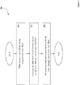
- FIG. 2 shown is a flow diagram of an example method 200 for managing turbine intake filters, according to an illustrative embodiment of the disclosure.
- the method 200 may be utilized in association with various systems, such as the system 100 illustrated in FIG. 1 .
- the method 200 may begin at block 210.
- at least one filter such as filter 120
- the filter may be of varying type and size, and with varying filtration performance characteristics, and may be operable to clean and/or remove impurities from air flowing through the intake.
- There may be amore than one filter associated with an intake and more than one filter associated with more than one intakes.
- Each filter may further be associated with a respective generating device.
- an indication based at least in part on air flow through the at least one filter may be generated by a respective generating device, such as the generating device 130 of FIG. 1 .
- the indication may include an indication of a particular condition of the at least one filter, for example, an indication of the amount of dirt or dust buildup on the filter.
- the indication may be compared with an initial or default indication which may represent an initial or default condition of the at least one filter.
- the respective generating device may include any reasonable means of indicating an air flow or an air flow assessment, such as, via wind chimes, a vibrating drum skin, a reed, and a perforated plate, for example.
- the method 200 can includes monitoring the indication from the generating device associated with the at least one filter.
- the indication may be detected and received by a control device, such as at least one control device 140 of FIG. 1 .
- the at least one control device may include a microphone operable to detect and receive the indication.
- the respective generating device may indicate a particular condition of the at least one filter, for example, the buildup of dust and dirt on the filter.
- Monitoring the indication may include detection of the indication composition, including a determination of the particular filter condition.
- the control device may be further operable to detect and receive indications from one or more generating devices, including indications associated with one or more filters, and indications associated with one or more turbine intake systems.
- the method 200 of FIG. 2 may optionally end following block 250.
- the operations described and shown in the method 200 of FIG. 2 may be carried out or performed in any suitable order as desired in various embodiments of the disclosure, and the method 200 may repeat any number of times. Additionally, in certain embodiments, at least a portion of the operations may be carried out in parallel. Furthermore, in certain embodiments, fewer than or more than the operations described in FIG. 2 may be performed.
- the system 300 may include a control module 356 associated with a controller 340.
- the control module 356 may be configured to monitor an indication associated with at least one intake filter 310 of a turbine intake system, like the system 100 of FIG. 1 .
- a generating device 315 may be associated with the intake filter 310.
- the generating device 315 may be operable to generate an indication associated with the condition of the filter 310, based at least in part on air flow through the filter 310.
- the indication may include an acoustic signal and/or a vibrational signal, for example.
- the control module 356 may be operable to detect and receive the indication.
- the indication may include an assessment of the air flow through the filter 310 and it may include a real-time representation of the air flow.
- the control module 356 may be operable to compare the indication with a history of indications associated with the at least one intake filter 310, with an indication detected or received soon after a pulsing of the at least one intake filter 310, as well as with indications associated with the at least one filter 310 which are detected or received by other monitoring devices 320 that may be associated with the same at least one filter 310.
- the control module 356 may be further operable to identify a condition of the intake filter 310 based at least in part on the detected or received indication.
- the control module 356 may further be operable to facilitate the execution of a management task, based at least in part on the indication.
- the management task may include manipulation of at least one pulsing device 380 operable to pulse the at least one intake filter 310, and replacement of the at least one intake filter 310, among other categories of managements tasks.
- the controller 340 may include any number of suitable computer processing components that may, among other things, facilitate the management of turbine intake filters.
- suitable processing devices that may be incorporated into the controller 340 include, but are not limited to, personal computers, tablet computers, wearable computers, personal digital assistants, mobile phones, application-specific circuits, microcontrollers, minicomputers, other computing devices, and the like.
- the controller 340 may include any number of processors 343 that facilitate the execution of computer-readable instructions. By executing computer-readable instructions, the controller 340 may include or form a special purpose computer or particular machine that facilitates processing of intake filter management.
- the controller 340 may include one or more memory devices 350, and/or one or more communications and/or network interfaces 346.
- the one or more memories 350 may include any suitable memory devices, for example, caches, read-only memory devices, random access memory devices, magnetic storage devices, etc.
- the one or more memories 350 may store filter and pulsing data, executable instructions, and/or various program modules utilized by the controller 340, for example, at least one control module 356 and an operating system ("O/S") 353.
- O/S operating system
- the one or more memories 350 may include any suitable data and applications that facilitate the operation of the controller 340 including, but not limited to, for communication between the controller 340, network 330, pulsing device 380, monitoring device 320, and the at least one intake filter 310. In certain embodiments, the one or more memories 350 may be further operable to store indications and/or pulse valve information associated with at least one intake filter 310.
- the O/S 353 may include executable instructions and/or program modules that facilitate and/or control the general operation of the controller 340.
- the O/S 353 may facilitate the execution of other software programs and/or program modules by the processor(s) 343, such as, the control module 356.
- the control module 356 may be a suitable software module with corresponding hardware capability configured to allow communication with objects outside the controller 340.
- the control module 356 may include one or more programming modules to facilitate management of turbine intake filters.
- the control module 356 may communicate with the monitoring device 320 and pulsing device 380 via network interface 346 and network 330.
- the control module 356 may be further operable to facilitate manipulation of the pulsing device 380 based at least in part on the indication generated by generating device 315 and detected or received by monitoring device 320.
- the control module 356 may provide pulsing parameters particular to the at least one intake filter 310 based at least in part on the indication associated with the at least one intake filter 310.
- the pulsing device 380 may be associated with at least one intake filter 310 and may pulse the filter 310 by cleaning or by causing air to travel through the filter 310, for example, by causing air to travel through the filter 310 in the opposite direction of the intake air.
- the pulsing device 380 may use varying types, strengths, and amounts of pulses for an intake filter 310, according to a filter condition, for example, an amount of buildup of dust and dirt on the filter 310.
- the control module 356 may therefore customize manipulation of the pulsing device 380 particular to a particular condition of intake filter 310 such as filter cleanliness.
- the control module 356 may be further operable to facilitate the manipulation of a plurality of pulsing devices 380 based at least in part on detecting and receiving indications associated with an individual intake filter 310 and/or associated with a group of filters.
- embodiments of the disclosure may include a system 300 with more or fewer components than are illustrated in FIG. 3 . Additionally, certain components of the system 300 may be combined in various embodiments of the disclosure.
- the system 300 of FIG. 3 is provided by way of example only.
- These computer-executable program instructions may be loaded onto a general purpose computer, a special purpose computer, a processor, or other programmable data processing apparatus to produce a particular machine, such that the instructions that execute on the computer, processor, or other programmable data processing apparatus create means for implementing one or more functions specified in the flow diagram block or blocks.
- These computer program instructions may also be stored in a computer-readable memory that can direct a computer or other programmable data processing apparatus to function in a particular manner, such that the instructions stored in the computer-readable memory produce an article of manufacture including instruction means that implement one or more functions specified in the flow diagram block or blocks.
- embodiments of the disclosure may provide for a computer program product, comprising a computer usable medium having a computer-readable program code or program instructions embodied therein, said computer-readable program code adapted to be executed to implement one or more functions specified in the flow diagram block or blocks.
- the computer program instructions may also be loaded onto a computer or other programmable data processing apparatus to cause a series of operational elements or steps to be performed on the computer or other programmable apparatus to produce a computer-implemented process such that the instructions that execute on the computer or other programmable apparatus provide elements or steps for implementing the functions specified in the flow diagram block or blocks.
- blocks of the block diagrams and flow diagrams support combinations of means for performing the specified functions, combinations of elements or steps for performing the specified functions and program instruction means for performing the specified functions. It will also be understood that each block of the block diagrams and flow diagrams, and combinations of blocks in the block diagrams and flow diagrams, can be implemented by special purpose, hardware-based computer systems that perform the specified functions, elements or steps, or combinations of special purpose hardware and computer instructions.
Landscapes
- Engineering & Computer Science (AREA)
- Chemical & Material Sciences (AREA)
- Mechanical Engineering (AREA)
- General Engineering & Computer Science (AREA)
- Chemical Kinetics & Catalysis (AREA)
- Combustion & Propulsion (AREA)
- Filtering Of Dispersed Particles In Gases (AREA)
- Control Of Turbines (AREA)
Claims (10)
- Système de filtres d'admission de turbine (100, 300), le système comprenant :une pluralité de filtres (120, 310) associés à au moins une admission de turbine (110) du système ;une pluralité de dispositifs (130, 315), chaque dispositif étant associé à un filtre respectif de la pluralité de filtres, le dispositif étant exploitable de manière à fournir une indication ;une pluralité de vannes à impulsions (180, 380) associées à la pluralité de filtres ; etau moins un dispositif de commande (140, 320, 356) exploitable de manière à détecter ou recevoir l'indication en provenance de chaque dispositif de la pluralité de dispositifs ;caractérisé en ce que l'indication est basée, au moins en partie, sur une mesure du débit d'air à travers le filtre respectif, dans laquelle l'indication se rapporte à une condition du filtre respectif, et en ce que ledit au moins un dispositif de commande est exploitable de manière à manipuler la pluralité de vannes à impulsions sur la base, au moins en partie, de l'indication associée au filtre respectif.
- Système de filtres d'admission de turbine selon la revendication 1, dans lequel l'indication comprend au moins un signal parmi (i) un signal acoustique ou (ii) un signal vibratoire.
- Système de filtres d'admission de turbine selon la revendication 1, dans lequel ledit au moins un dispositif de commande est en outre exploitable de manière à détecter ou recevoir une pluralité d'indications en provenance d'un dispositif respectif de la pluralité de dispositifs.
- Système de filtres d'admission de turbine selon la revendication 1, dans lequel ledit au moins un dispositif de commande est en outre exploitable de manière à déterminer une variance du débit d'air sur la base, au moins en partie, de l'indication détectée ou reçue et d'un seuil prédéfini associé au filtre respectif.
- Système de filtres d'admission de turbine selon la revendication 1, dans lequel le dispositif de commande (356) est exploitable de manière à identifier une condition d'au moins un filtre de la pluralité de filtres, sur la base, au moins en partie, de l'indication détectée ou reçue respective dudit au moins un filtre de la pluralité de filtres.
- Procédé de gestion de filtres d'admission de turbine, le procédé comprenant les étapes consistant à :filtrer au moins une admission de turbine (110, 310) en utilisant une pluralité de filtres (120) ;générer, par le biais de chaque dispositif d'une pluralité de dispositifs (130, 315), où chaque dispositif est associé à un filtre respectif de la pluralité de filtres, une indication basée, au moins en partie, sur une mesure du débit d'air à travers le filtre respectif ;surveiller, par le biais d'au moins un dispositif de surveillance (320) associé à la pluralité de filtres, l'indication de chaque dispositif de la pluralité de dispositifs, dans laquelle l'indication se rapporte à une condition du filtre respectif ; etenvoyer une impulsion à au moins un filtre de la pluralité de filtres sur la base, au moins en partie, de l'indication du dispositif respectif.
- Procédé selon la revendication 6, dans lequel ledit au moins un dispositif de surveillance est en outre exploitable de manière à diriger l'envoi d'impulsion d'au moins un dispositif d'envoi d'impulsion (180, 380).
- Procédé selon la revendication 6, dans lequel l'étape de génération de l'indication consiste en outre à générer au moins (i) un signal acoustique ou (ii) un signal vibratoire.
- Procédé selon la revendication 6, comprenant en outre l'étape consistant à déterminer une variance du débit d'air sur la base, au moins en partie, de l'indication détectée ou reçue et d'un seuil prédéfini associé au filtre respectif.
- Procédé selon la revendication 6, dans lequel l'étape de surveillance de l'indication comprend l'étape consistant à détecter une composition de l'indication et l'étape consistant à déterminer une condition du filtre respectif.
Applications Claiming Priority (2)
| Application Number | Priority Date | Filing Date | Title |
|---|---|---|---|
| US14/082,995 US9387426B2 (en) | 2013-11-18 | 2013-11-18 | Systems and methods for managing turbine intake filters |
| PCT/US2014/065450 WO2015073669A1 (fr) | 2013-11-18 | 2014-11-13 | Systèmes et procédés pour gérer des filtres d'admission de turbine |
Publications (3)
| Publication Number | Publication Date |
|---|---|
| EP3071815A1 EP3071815A1 (fr) | 2016-09-28 |
| EP3071815A4 EP3071815A4 (fr) | 2017-07-12 |
| EP3071815B1 true EP3071815B1 (fr) | 2022-08-17 |
Family
ID=53058009
Family Applications (1)
| Application Number | Title | Priority Date | Filing Date |
|---|---|---|---|
| EP14861439.9A Active EP3071815B1 (fr) | 2013-11-18 | 2014-11-13 | Systèmes et procédés pour gérer des filtres d'admission de turbine |
Country Status (6)
| Country | Link |
|---|---|
| US (1) | US9387426B2 (fr) |
| EP (1) | EP3071815B1 (fr) |
| CA (1) | CA2930863C (fr) |
| MX (1) | MX388690B (fr) |
| SA (1) | SA516371135B1 (fr) |
| WO (1) | WO2015073669A1 (fr) |
Families Citing this family (3)
| Publication number | Priority date | Publication date | Assignee | Title |
|---|---|---|---|---|
| SE539464C2 (en) | 2016-02-24 | 2017-09-26 | Camfil Ab | System, method and computer program product for air filter management |
| US10780385B2 (en) | 2017-05-30 | 2020-09-22 | General Electric Company | System and method for condition-based monitoring of filters |
| KR102102805B1 (ko) * | 2018-03-14 | 2020-04-22 | 두산중공업 주식회사 | 고장 감지 장치 및 가스터빈 |
Citations (3)
| Publication number | Priority date | Publication date | Assignee | Title |
|---|---|---|---|---|
| US20110185895A1 (en) * | 2010-02-03 | 2011-08-04 | Paul Freen | Filter apparatus and method of monitoring filter apparatus |
| KR20110106965A (ko) * | 2010-03-24 | 2011-09-30 | 한국에너지기술연구원 | 대용량 여과집진기 탈진 장치 및 방법 |
| EP2638946A1 (fr) * | 2012-03-14 | 2013-09-18 | Dutchap B.V. | Unité de capteur et procédé de mesure d'un écoulement de fluide |
Family Cites Families (23)
| Publication number | Priority date | Publication date | Assignee | Title |
|---|---|---|---|---|
| JPS62101843A (ja) | 1985-10-29 | 1987-05-12 | Hitachi Ltd | ガスタ−ビン吸気装置用セルフクリ−ニング機構 |
| US4786293A (en) * | 1987-10-08 | 1988-11-22 | Farr Company | Smart controller for reverse pulse air filter |
| NL9300554A (nl) * | 1993-03-29 | 1994-10-17 | Doctro A V V | Samenstel van filterinrichting en een vervangbaar filter; alsmede filterinrichting en filter voor toepassing daarin. |
| JPH07208206A (ja) | 1994-01-18 | 1995-08-08 | Hitachi Ltd | ガスタービン圧縮機翼面汚れ防止装置 |
| ATE211940T1 (de) * | 1997-10-31 | 2002-02-15 | Niro Atomizer As | Gasfilter und verfahren zur reinigung desselben |
| US7481917B2 (en) | 2004-03-05 | 2009-01-27 | Hydranautics | Filtration devices with embedded radio frequency identification (RFID) tags |
| US8617397B2 (en) | 2005-09-07 | 2013-12-31 | Hydranautics | Reverse osmosis filtration devices with RFID tag-powered flow and conductivity meters |
| JP4427526B2 (ja) | 2006-07-13 | 2010-03-10 | 三菱重工業株式会社 | ガスタービン吸気装置の運転方法 |
| US7811365B2 (en) * | 2006-10-16 | 2010-10-12 | Millipore Corporation | Wireless receptor for communications within housings |
| EP1923651A1 (fr) | 2006-11-20 | 2008-05-21 | Donaldson Company, Inc. | Système d'admission de gaz |
| DE102007005310A1 (de) * | 2007-02-02 | 2008-08-07 | Itw Gema Ag | Beschichtungspulver-Filtervorrichtung |
| US20080229927A1 (en) * | 2007-03-23 | 2008-09-25 | Bha Group, Inc. | Filter cleaning control system and method |
| US20090045106A1 (en) | 2007-08-15 | 2009-02-19 | Access Business Group International Llc | Water treatment system |
| US8815371B2 (en) | 2008-09-22 | 2014-08-26 | Siemens Energy, Inc. | Structure and method for forming detailed channels for thin walled components using thermal spraying |
| US8163072B2 (en) * | 2009-04-20 | 2012-04-24 | General Electric Company | Filter washing system for gas turbine engines |
| US8657936B2 (en) * | 2009-09-16 | 2014-02-25 | Challen Sullivan | Direct replacement air filter with automatic filter media advance and wireless communications |
| US8234874B2 (en) | 2009-10-09 | 2012-08-07 | General Electric Company | Systems and methods for bypassing an inlet air treatment filter |
| US20130048550A1 (en) | 2011-08-22 | 2013-02-28 | Access Business Group International Llc | Water treatment system with sealing enclosure |
| US20140237763A1 (en) * | 2012-11-06 | 2014-08-28 | Stuart V. Holsten | Backflush Filter Cleaning System and Method of Use |
| US20140123853A1 (en) * | 2012-11-08 | 2014-05-08 | Bha Altair, Llc | Offline water wash system for inlet filters and filter house |
| US8747533B1 (en) * | 2013-01-28 | 2014-06-10 | Bha Altair, Llc | Systems and methods to determine fouling in a gas turbine filter |
| US20140251129A1 (en) * | 2013-03-11 | 2014-09-11 | Bha Altair, Llc | Automatic coalescer replacement system and method |
| US9797812B2 (en) * | 2013-03-19 | 2017-10-24 | International Business Machines Corporation | Filter replacement lifetime prediction |
-
2013
- 2013-11-18 US US14/082,995 patent/US9387426B2/en active Active
-
2014
- 2014-11-13 MX MX2016006343A patent/MX388690B/es unknown
- 2014-11-13 WO PCT/US2014/065450 patent/WO2015073669A1/fr not_active Ceased
- 2014-11-13 EP EP14861439.9A patent/EP3071815B1/fr active Active
- 2014-11-13 CA CA2930863A patent/CA2930863C/fr active Active
-
2016
- 2016-05-17 SA SA516371135A patent/SA516371135B1/ar unknown
Patent Citations (3)
| Publication number | Priority date | Publication date | Assignee | Title |
|---|---|---|---|---|
| US20110185895A1 (en) * | 2010-02-03 | 2011-08-04 | Paul Freen | Filter apparatus and method of monitoring filter apparatus |
| KR20110106965A (ko) * | 2010-03-24 | 2011-09-30 | 한국에너지기술연구원 | 대용량 여과집진기 탈진 장치 및 방법 |
| EP2638946A1 (fr) * | 2012-03-14 | 2013-09-18 | Dutchap B.V. | Unité de capteur et procédé de mesure d'un écoulement de fluide |
Also Published As
| Publication number | Publication date |
|---|---|
| SA516371135B1 (ar) | 2021-04-11 |
| WO2015073669A1 (fr) | 2015-05-21 |
| EP3071815A1 (fr) | 2016-09-28 |
| CA2930863C (fr) | 2022-07-12 |
| CA2930863A1 (fr) | 2015-05-21 |
| EP3071815A4 (fr) | 2017-07-12 |
| MX2016006343A (es) | 2016-08-01 |
| US20150135948A1 (en) | 2015-05-21 |
| US9387426B2 (en) | 2016-07-12 |
| MX388690B (es) | 2025-03-20 |
Similar Documents
| Publication | Publication Date | Title |
|---|---|---|
| EP3409923B1 (fr) | Système de surveillance basée sur l'état de filtres | |
| EP3681616B1 (fr) | Système et procédé de télésurveillance de performance à vanne à jet d'impulsion | |
| US9314742B2 (en) | Method and system for reverse osmosis predictive maintenance using normalization data | |
| EP3071815B1 (fr) | Systèmes et procédés pour gérer des filtres d'admission de turbine | |
| CN105275690B (zh) | 燃料过滤器异常检测装置 | |
| KR102139147B1 (ko) | 여과 집진기의 모니터링 시스템 | |
| US20200298163A1 (en) | Filter diagnostic system and method | |
| EP3926160B1 (fr) | Dispositif de détermination de détérioration de filtre à air d'une machine de construction | |
| EP3977020B1 (fr) | Systèmes et procédés de détection de l'état d'un filtre à particules | |
| CN119386577A (zh) | 袋式除尘器清灰监测方法、装置、系统及介质 | |
| RU2658408C2 (ru) | Распознавание процесса очистки установки с фильтрами, размещенными с пространственным смещением относительно друг друга | |
| CN120470938A (zh) | 过滤分离设备的运维方法、装置、设备及可读存储介质 | |
| EP3339997B1 (fr) | Système et procédé de commande d'installation sur la base de la qualité d'un fluide | |
| CN114396340B (zh) | 一种燃气轮机进气系统的监控方法、装置及电子设备 | |
| KR20260009299A (ko) | 필터 상태를 결정하기 위한 시스템 | |
| CN105874393B (zh) | 用于引导流体的生产系统的监控系统和方法 | |
| CN117704290B (en) | Intelligent valve control system | |
| CN115076900A (zh) | 滤网使用寿命的监控方法、装置及空调 | |
| CN117704290A (zh) | 一种智慧阀门控制系统 | |
| CN116950956A (zh) | 用于工程机械的液压油检测与自清洁系统以及方法 | |
| RU2008123064A (ru) | Способ повышения достоверности поступающей информации в автоматизированной системе управления технологическими процессами, функционирующей в условиях крайнего севера | |
| US20060207229A1 (en) | Autonomously-cleaned conditioning system | |
| JP2013212473A (ja) | 浄水器 |
Legal Events
| Date | Code | Title | Description |
|---|---|---|---|
| PUAI | Public reference made under article 153(3) epc to a published international application that has entered the european phase |
Free format text: ORIGINAL CODE: 0009012 |
|
| 17P | Request for examination filed |
Effective date: 20160524 |
|
| AK | Designated contracting states |
Kind code of ref document: A1 Designated state(s): AL AT BE BG CH CY CZ DE DK EE ES FI FR GB GR HR HU IE IS IT LI LT LU LV MC MK MT NL NO PL PT RO RS SE SI SK SM TR |
|
| AX | Request for extension of the european patent |
Extension state: BA ME |
|
| RIN1 | Information on inventor provided before grant (corrected) |
Inventor name: HINER, STEPHEN DAVID Inventor name: BRYANT, PAUL SHERWOOD |
|
| DAX | Request for extension of the european patent (deleted) | ||
| A4 | Supplementary search report drawn up and despatched |
Effective date: 20170609 |
|
| RIC1 | Information provided on ipc code assigned before grant |
Ipc: F02C 7/052 20060101ALI20170602BHEP Ipc: F02C 7/05 20060101AFI20170602BHEP |
|
| STAA | Information on the status of an ep patent application or granted ep patent |
Free format text: STATUS: EXAMINATION IS IN PROGRESS |
|
| 17Q | First examination report despatched |
Effective date: 20190708 |
|
| RAP1 | Party data changed (applicant data changed or rights of an application transferred) |
Owner name: PARKER-HANNIFIN CORPORATION |
|
| GRAP | Despatch of communication of intention to grant a patent |
Free format text: ORIGINAL CODE: EPIDOSNIGR1 |
|
| STAA | Information on the status of an ep patent application or granted ep patent |
Free format text: STATUS: GRANT OF PATENT IS INTENDED |
|
| INTG | Intention to grant announced |
Effective date: 20220310 |
|
| GRAS | Grant fee paid |
Free format text: ORIGINAL CODE: EPIDOSNIGR3 |
|
| GRAA | (expected) grant |
Free format text: ORIGINAL CODE: 0009210 |
|
| STAA | Information on the status of an ep patent application or granted ep patent |
Free format text: STATUS: THE PATENT HAS BEEN GRANTED |
|
| AK | Designated contracting states |
Kind code of ref document: B1 Designated state(s): AL AT BE BG CH CY CZ DE DK EE ES FI FR GB GR HR HU IE IS IT LI LT LU LV MC MK MT NL NO PL PT RO RS SE SI SK SM TR |
|
| REG | Reference to a national code |
Ref country code: CH Ref legal event code: EP |
|
| REG | Reference to a national code |
Ref country code: DE Ref legal event code: R096 Ref document number: 602014084665 Country of ref document: DE |
|
| REG | Reference to a national code |
Ref country code: IE Ref legal event code: FG4D |
|
| REG | Reference to a national code |
Ref country code: AT Ref legal event code: REF Ref document number: 1512336 Country of ref document: AT Kind code of ref document: T Effective date: 20220915 |
|
| REG | Reference to a national code |
Ref country code: SE Ref legal event code: TRGR |
|
| REG | Reference to a national code |
Ref country code: NL Ref legal event code: MP Effective date: 20220817 |
|
| REG | Reference to a national code |
Ref country code: LT Ref legal event code: MG9D |
|
| PG25 | Lapsed in a contracting state [announced via postgrant information from national office to epo] |
Ref country code: RS Free format text: LAPSE BECAUSE OF FAILURE TO SUBMIT A TRANSLATION OF THE DESCRIPTION OR TO PAY THE FEE WITHIN THE PRESCRIBED TIME-LIMIT Effective date: 20220817 Ref country code: PT Free format text: LAPSE BECAUSE OF FAILURE TO SUBMIT A TRANSLATION OF THE DESCRIPTION OR TO PAY THE FEE WITHIN THE PRESCRIBED TIME-LIMIT Effective date: 20221219 Ref country code: NO Free format text: LAPSE BECAUSE OF FAILURE TO SUBMIT A TRANSLATION OF THE DESCRIPTION OR TO PAY THE FEE WITHIN THE PRESCRIBED TIME-LIMIT Effective date: 20221117 Ref country code: NL Free format text: LAPSE BECAUSE OF FAILURE TO SUBMIT A TRANSLATION OF THE DESCRIPTION OR TO PAY THE FEE WITHIN THE PRESCRIBED TIME-LIMIT Effective date: 20220817 Ref country code: LV Free format text: LAPSE BECAUSE OF FAILURE TO SUBMIT A TRANSLATION OF THE DESCRIPTION OR TO PAY THE FEE WITHIN THE PRESCRIBED TIME-LIMIT Effective date: 20220817 Ref country code: LT Free format text: LAPSE BECAUSE OF FAILURE TO SUBMIT A TRANSLATION OF THE DESCRIPTION OR TO PAY THE FEE WITHIN THE PRESCRIBED TIME-LIMIT Effective date: 20220817 Ref country code: FI Free format text: LAPSE BECAUSE OF FAILURE TO SUBMIT A TRANSLATION OF THE DESCRIPTION OR TO PAY THE FEE WITHIN THE PRESCRIBED TIME-LIMIT Effective date: 20220817 Ref country code: ES Free format text: LAPSE BECAUSE OF FAILURE TO SUBMIT A TRANSLATION OF THE DESCRIPTION OR TO PAY THE FEE WITHIN THE PRESCRIBED TIME-LIMIT Effective date: 20220817 |
|
| REG | Reference to a national code |
Ref country code: AT Ref legal event code: MK05 Ref document number: 1512336 Country of ref document: AT Kind code of ref document: T Effective date: 20220817 |
|
| PG25 | Lapsed in a contracting state [announced via postgrant information from national office to epo] |
Ref country code: PL Free format text: LAPSE BECAUSE OF FAILURE TO SUBMIT A TRANSLATION OF THE DESCRIPTION OR TO PAY THE FEE WITHIN THE PRESCRIBED TIME-LIMIT Effective date: 20220817 Ref country code: IS Free format text: LAPSE BECAUSE OF FAILURE TO SUBMIT A TRANSLATION OF THE DESCRIPTION OR TO PAY THE FEE WITHIN THE PRESCRIBED TIME-LIMIT Effective date: 20221217 Ref country code: HR Free format text: LAPSE BECAUSE OF FAILURE TO SUBMIT A TRANSLATION OF THE DESCRIPTION OR TO PAY THE FEE WITHIN THE PRESCRIBED TIME-LIMIT Effective date: 20220817 Ref country code: GR Free format text: LAPSE BECAUSE OF FAILURE TO SUBMIT A TRANSLATION OF THE DESCRIPTION OR TO PAY THE FEE WITHIN THE PRESCRIBED TIME-LIMIT Effective date: 20221118 |
|
| PG25 | Lapsed in a contracting state [announced via postgrant information from national office to epo] |
Ref country code: SM Free format text: LAPSE BECAUSE OF FAILURE TO SUBMIT A TRANSLATION OF THE DESCRIPTION OR TO PAY THE FEE WITHIN THE PRESCRIBED TIME-LIMIT Effective date: 20220817 Ref country code: RO Free format text: LAPSE BECAUSE OF FAILURE TO SUBMIT A TRANSLATION OF THE DESCRIPTION OR TO PAY THE FEE WITHIN THE PRESCRIBED TIME-LIMIT Effective date: 20220817 Ref country code: DK Free format text: LAPSE BECAUSE OF FAILURE TO SUBMIT A TRANSLATION OF THE DESCRIPTION OR TO PAY THE FEE WITHIN THE PRESCRIBED TIME-LIMIT Effective date: 20220817 Ref country code: CZ Free format text: LAPSE BECAUSE OF FAILURE TO SUBMIT A TRANSLATION OF THE DESCRIPTION OR TO PAY THE FEE WITHIN THE PRESCRIBED TIME-LIMIT Effective date: 20220817 Ref country code: AT Free format text: LAPSE BECAUSE OF FAILURE TO SUBMIT A TRANSLATION OF THE DESCRIPTION OR TO PAY THE FEE WITHIN THE PRESCRIBED TIME-LIMIT Effective date: 20220817 |
|
| REG | Reference to a national code |
Ref country code: DE Ref legal event code: R097 Ref document number: 602014084665 Country of ref document: DE |
|
| PG25 | Lapsed in a contracting state [announced via postgrant information from national office to epo] |
Ref country code: SK Free format text: LAPSE BECAUSE OF FAILURE TO SUBMIT A TRANSLATION OF THE DESCRIPTION OR TO PAY THE FEE WITHIN THE PRESCRIBED TIME-LIMIT Effective date: 20220817 Ref country code: EE Free format text: LAPSE BECAUSE OF FAILURE TO SUBMIT A TRANSLATION OF THE DESCRIPTION OR TO PAY THE FEE WITHIN THE PRESCRIBED TIME-LIMIT Effective date: 20220817 |
|
| PLBE | No opposition filed within time limit |
Free format text: ORIGINAL CODE: 0009261 |
|
| STAA | Information on the status of an ep patent application or granted ep patent |
Free format text: STATUS: NO OPPOSITION FILED WITHIN TIME LIMIT |
|
| P01 | Opt-out of the competence of the unified patent court (upc) registered |
Effective date: 20230524 |
|
| PG25 | Lapsed in a contracting state [announced via postgrant information from national office to epo] |
Ref country code: MC Free format text: LAPSE BECAUSE OF FAILURE TO SUBMIT A TRANSLATION OF THE DESCRIPTION OR TO PAY THE FEE WITHIN THE PRESCRIBED TIME-LIMIT Effective date: 20220817 Ref country code: AL Free format text: LAPSE BECAUSE OF FAILURE TO SUBMIT A TRANSLATION OF THE DESCRIPTION OR TO PAY THE FEE WITHIN THE PRESCRIBED TIME-LIMIT Effective date: 20220817 |
|
| REG | Reference to a national code |
Ref country code: CH Ref legal event code: PL |
|
| 26N | No opposition filed |
Effective date: 20230519 |
|
| PG25 | Lapsed in a contracting state [announced via postgrant information from national office to epo] |
Ref country code: LI Free format text: LAPSE BECAUSE OF NON-PAYMENT OF DUE FEES Effective date: 20221130 Ref country code: CH Free format text: LAPSE BECAUSE OF NON-PAYMENT OF DUE FEES Effective date: 20221130 |
|
| PG25 | Lapsed in a contracting state [announced via postgrant information from national office to epo] |
Ref country code: SI Free format text: LAPSE BECAUSE OF FAILURE TO SUBMIT A TRANSLATION OF THE DESCRIPTION OR TO PAY THE FEE WITHIN THE PRESCRIBED TIME-LIMIT Effective date: 20220817 Ref country code: LU Free format text: LAPSE BECAUSE OF NON-PAYMENT OF DUE FEES Effective date: 20221113 |
|
| PG25 | Lapsed in a contracting state [announced via postgrant information from national office to epo] |
Ref country code: IE Free format text: LAPSE BECAUSE OF NON-PAYMENT OF DUE FEES Effective date: 20221113 |
|
| PG25 | Lapsed in a contracting state [announced via postgrant information from national office to epo] |
Ref country code: HU Free format text: LAPSE BECAUSE OF FAILURE TO SUBMIT A TRANSLATION OF THE DESCRIPTION OR TO PAY THE FEE WITHIN THE PRESCRIBED TIME-LIMIT; INVALID AB INITIO Effective date: 20141113 |
|
| PG25 | Lapsed in a contracting state [announced via postgrant information from national office to epo] |
Ref country code: CY Free format text: LAPSE BECAUSE OF FAILURE TO SUBMIT A TRANSLATION OF THE DESCRIPTION OR TO PAY THE FEE WITHIN THE PRESCRIBED TIME-LIMIT Effective date: 20220817 |
|
| PG25 | Lapsed in a contracting state [announced via postgrant information from national office to epo] |
Ref country code: MK Free format text: LAPSE BECAUSE OF FAILURE TO SUBMIT A TRANSLATION OF THE DESCRIPTION OR TO PAY THE FEE WITHIN THE PRESCRIBED TIME-LIMIT Effective date: 20220817 |
|
| PG25 | Lapsed in a contracting state [announced via postgrant information from national office to epo] |
Ref country code: TR Free format text: LAPSE BECAUSE OF FAILURE TO SUBMIT A TRANSLATION OF THE DESCRIPTION OR TO PAY THE FEE WITHIN THE PRESCRIBED TIME-LIMIT Effective date: 20220817 |
|
| PG25 | Lapsed in a contracting state [announced via postgrant information from national office to epo] |
Ref country code: BG Free format text: LAPSE BECAUSE OF FAILURE TO SUBMIT A TRANSLATION OF THE DESCRIPTION OR TO PAY THE FEE WITHIN THE PRESCRIBED TIME-LIMIT Effective date: 20220817 |
|
| PG25 | Lapsed in a contracting state [announced via postgrant information from national office to epo] |
Ref country code: MT Free format text: LAPSE BECAUSE OF FAILURE TO SUBMIT A TRANSLATION OF THE DESCRIPTION OR TO PAY THE FEE WITHIN THE PRESCRIBED TIME-LIMIT Effective date: 20220817 |
|
| PGFP | Annual fee paid to national office [announced via postgrant information from national office to epo] |
Ref country code: DE Payment date: 20251128 Year of fee payment: 12 |
|
| PGFP | Annual fee paid to national office [announced via postgrant information from national office to epo] |
Ref country code: GB Payment date: 20251127 Year of fee payment: 12 |
|
| PGFP | Annual fee paid to national office [announced via postgrant information from national office to epo] |
Ref country code: IT Payment date: 20251119 Year of fee payment: 12 |
|
| PGFP | Annual fee paid to national office [announced via postgrant information from national office to epo] |
Ref country code: FR Payment date: 20251125 Year of fee payment: 12 |
|
| PGFP | Annual fee paid to national office [announced via postgrant information from national office to epo] |
Ref country code: BE Payment date: 20251127 Year of fee payment: 12 |
|
| PGFP | Annual fee paid to national office [announced via postgrant information from national office to epo] |
Ref country code: SE Payment date: 20251127 Year of fee payment: 12 |