EP3071909B1 - Kühlschrank - Google Patents
Kühlschrank Download PDFInfo
- Publication number
- EP3071909B1 EP3071909B1 EP14861962.0A EP14861962A EP3071909B1 EP 3071909 B1 EP3071909 B1 EP 3071909B1 EP 14861962 A EP14861962 A EP 14861962A EP 3071909 B1 EP3071909 B1 EP 3071909B1
- Authority
- EP
- European Patent Office
- Prior art keywords
- door
- opened
- locking part
- internal
- external door
- Prior art date
- Legal status (The legal status is an assumption and is not a legal conclusion. Google has not performed a legal analysis and makes no representation as to the accuracy of the status listed.)
- Active
Links
Images




Classifications
-
- F—MECHANICAL ENGINEERING; LIGHTING; HEATING; WEAPONS; BLASTING
- F25—REFRIGERATION OR COOLING; COMBINED HEATING AND REFRIGERATION SYSTEMS; HEAT PUMP SYSTEMS; MANUFACTURE OR STORAGE OF ICE; LIQUEFACTION SOLIDIFICATION OF GASES
- F25D—REFRIGERATORS; COLD ROOMS; ICE-BOXES; COOLING OR FREEZING APPARATUS NOT OTHERWISE PROVIDED FOR
- F25D23/00—General constructional features
- F25D23/02—Doors; Covers
- F25D23/028—Details
-
- F—MECHANICAL ENGINEERING; LIGHTING; HEATING; WEAPONS; BLASTING
- F25—REFRIGERATION OR COOLING; COMBINED HEATING AND REFRIGERATION SYSTEMS; HEAT PUMP SYSTEMS; MANUFACTURE OR STORAGE OF ICE; LIQUEFACTION SOLIDIFICATION OF GASES
- F25D—REFRIGERATORS; COLD ROOMS; ICE-BOXES; COOLING OR FREEZING APPARATUS NOT OTHERWISE PROVIDED FOR
- F25D23/00—General constructional features
- F25D23/02—Doors; Covers
-
- E—FIXED CONSTRUCTIONS
- E05—LOCKS; KEYS; WINDOW OR DOOR FITTINGS; SAFES
- E05B—LOCKS; ACCESSORIES THEREFOR; HANDCUFFS
- E05B65/00—Locks or fastenings for special use
- E05B65/0042—For refrigerators or cold rooms
-
- E—FIXED CONSTRUCTIONS
- E05—LOCKS; KEYS; WINDOW OR DOOR FITTINGS; SAFES
- E05C—BOLTS OR FASTENING DEVICES FOR WINGS, SPECIALLY FOR DOORS OR WINDOWS
- E05C7/00—Fastening devices specially adapted for two wings
- E05C7/02—Fastening devices specially adapted for two wings for wings which lie one behind the other when closed
-
- E—FIXED CONSTRUCTIONS
- E05—LOCKS; KEYS; WINDOW OR DOOR FITTINGS; SAFES
- E05D—HINGES OR SUSPENSION DEVICES FOR DOORS, WINDOWS OR WINGS
- E05D11/00—Additional features or accessories of hinges
- E05D11/06—Devices for limiting the opening movement of hinges
-
- E—FIXED CONSTRUCTIONS
- E05—LOCKS; KEYS; WINDOW OR DOOR FITTINGS; SAFES
- E05D—HINGES OR SUSPENSION DEVICES FOR DOORS, WINDOWS OR WINGS
- E05D11/00—Additional features or accessories of hinges
- E05D11/08—Friction devices between relatively-movable hinge parts
-
- E—FIXED CONSTRUCTIONS
- E05—LOCKS; KEYS; WINDOW OR DOOR FITTINGS; SAFES
- E05D—HINGES OR SUSPENSION DEVICES FOR DOORS, WINDOWS OR WINGS
- E05D11/00—Additional features or accessories of hinges
- E05D11/10—Devices for preventing movement between relatively-movable hinge parts
-
- E—FIXED CONSTRUCTIONS
- E05—LOCKS; KEYS; WINDOW OR DOOR FITTINGS; SAFES
- E05D—HINGES OR SUSPENSION DEVICES FOR DOORS, WINDOWS OR WINGS
- E05D7/00—Hinges or pivots of special construction
-
- F—MECHANICAL ENGINEERING; LIGHTING; HEATING; WEAPONS; BLASTING
- F25—REFRIGERATION OR COOLING; COMBINED HEATING AND REFRIGERATION SYSTEMS; HEAT PUMP SYSTEMS; MANUFACTURE OR STORAGE OF ICE; LIQUEFACTION SOLIDIFICATION OF GASES
- F25D—REFRIGERATORS; COLD ROOMS; ICE-BOXES; COOLING OR FREEZING APPARATUS NOT OTHERWISE PROVIDED FOR
- F25D23/00—General constructional features
- F25D23/02—Doors; Covers
- F25D23/04—Doors; Covers with special compartments, e.g. butter conditioners
-
- F—MECHANICAL ENGINEERING; LIGHTING; HEATING; WEAPONS; BLASTING
- F25—REFRIGERATION OR COOLING; COMBINED HEATING AND REFRIGERATION SYSTEMS; HEAT PUMP SYSTEMS; MANUFACTURE OR STORAGE OF ICE; LIQUEFACTION SOLIDIFICATION OF GASES
- F25D—REFRIGERATORS; COLD ROOMS; ICE-BOXES; COOLING OR FREEZING APPARATUS NOT OTHERWISE PROVIDED FOR
- F25D23/00—General constructional features
- F25D23/06—Walls
- F25D23/062—Walls defining a cabinet
-
- E—FIXED CONSTRUCTIONS
- E05—LOCKS; KEYS; WINDOW OR DOOR FITTINGS; SAFES
- E05B—LOCKS; ACCESSORIES THEREFOR; HANDCUFFS
- E05B85/00—Details of vehicle locks not provided for in groups E05B77/00 - E05B83/00
- E05B85/20—Bolts or detents
- E05B85/24—Bolts rotating about an axis
- E05B85/26—Cooperation between bolts and detents
-
- E—FIXED CONSTRUCTIONS
- E05—LOCKS; KEYS; WINDOW OR DOOR FITTINGS; SAFES
- E05D—HINGES OR SUSPENSION DEVICES FOR DOORS, WINDOWS OR WINGS
- E05D7/00—Hinges or pivots of special construction
- E05D7/08—Hinges or pivots of special construction for use in suspensions comprising two spigots placed at opposite edges of the wing, especially at the top and the bottom, e.g. trunnions
- E05D7/081—Hinges or pivots of special construction for use in suspensions comprising two spigots placed at opposite edges of the wing, especially at the top and the bottom, e.g. trunnions the pivot axis of the wing being situated near one edge of the wing, especially at the top and bottom, e.g. trunnions
-
- E—FIXED CONSTRUCTIONS
- E05—LOCKS; KEYS; WINDOW OR DOOR FITTINGS; SAFES
- E05Y—INDEXING SCHEME ASSOCIATED WITH SUBCLASSES E05D AND E05F, RELATING TO CONSTRUCTION ELEMENTS, ELECTRIC CONTROL, POWER SUPPLY, POWER SIGNAL OR TRANSMISSION, USER INTERFACES, MOUNTING OR COUPLING, DETAILS, ACCESSORIES, AUXILIARY OPERATIONS NOT OTHERWISE PROVIDED FOR, APPLICATION THEREOF
- E05Y2900/00—Application of doors, windows, wings or fittings thereof
- E05Y2900/30—Application of doors, windows, wings or fittings thereof for domestic appliances
- E05Y2900/31—Application of doors, windows, wings or fittings thereof for domestic appliances for refrigerators
-
- F—MECHANICAL ENGINEERING; LIGHTING; HEATING; WEAPONS; BLASTING
- F25—REFRIGERATION OR COOLING; COMBINED HEATING AND REFRIGERATION SYSTEMS; HEAT PUMP SYSTEMS; MANUFACTURE OR STORAGE OF ICE; LIQUEFACTION SOLIDIFICATION OF GASES
- F25D—REFRIGERATORS; COLD ROOMS; ICE-BOXES; COOLING OR FREEZING APPARATUS NOT OTHERWISE PROVIDED FOR
- F25D2323/00—General constructional features not provided for in other groups of this subclass
- F25D2323/02—Details of doors or covers not otherwise covered
- F25D2323/023—Door in door constructions
-
- Y—GENERAL TAGGING OF NEW TECHNOLOGICAL DEVELOPMENTS; GENERAL TAGGING OF CROSS-SECTIONAL TECHNOLOGIES SPANNING OVER SEVERAL SECTIONS OF THE IPC; TECHNICAL SUBJECTS COVERED BY FORMER USPC CROSS-REFERENCE ART COLLECTIONS [XRACs] AND DIGESTS
- Y10—TECHNICAL SUBJECTS COVERED BY FORMER USPC
- Y10T—TECHNICAL SUBJECTS COVERED BY FORMER US CLASSIFICATION
- Y10T292/00—Closure fasteners
- Y10T292/08—Bolts
- Y10T292/1043—Swinging
Definitions
- One or more embodiments relate to a refrigerator which has an internal door rotatably disposed at a main body so as to open and close a storage chamber and having an opening part, and an external door rotatably disposed at the internal door so as to open and close the opening part.
- a refrigerator is a home appliance which has a storage chamber storing food and a cold air supplying device supplying cold air to the storage chamber so as to keep the food fresh for a long time.
- a shelf on which to put the food is provided at the storage chamber, and the storage chamber has an opened front surface through which to store and take out the food.
- the opened front surface of the storage chamber may be opened and closed by an internal door which is rotatably coupled to a main body, and the internal door has an opening part.
- the opening part formed in the internal door may be opened and closed by an external door which is rotatably coupled to the internal door.
- Gaskets are provided at each rear surface of the internal door and the external door in order to maintain airtightness between the internal door and the main body and between the internal door and the external door.
- the internal door may be opened together by an inertial force of the external door.
- the external door may be undesirably opened by the inertial force.
- Patent documents EP2565 565 A2 , US 29 42 438 and US 30 868 30 describe refrigerators having such internal and external doors.
- a refrigerator in accordance with the invention defined in claim 1, includes a main body, a storage chamber provided in the main body so that a front surface thereof is opened, an internal door rotatably provided at a front surface of the main body so as to open and close the storage chamber and having an opening part in which a plurality of door guards are provided, an external door rotatably provided at a front surface of the internal door so as to open and close the opening part, and an internal door opening prevention device allowing or preventing opening of the internal door according to whether the external door is opened or closed.
- the internal door opening prevention device allows the internal door to be opened when the external door is closed, and prevents the internal door from being opened when the external door is opened.
- the internal door opening prevention device includes a stopper coupled to a lower portion of the main body, a locking part rotatably coupled to a lower portion of the internal door and rotated according to whether the external door is opened or closed so as to be locked and unlocked with the stopper, a spring configured to elastically support the locking part, and a cover configured to cover the locking part so as to prevent the locking part from being exposed to an outside and having a rotational protrusion to which the locking part is rotatably coupled.
- the stopper and the cover are respectively coupled to the lower portion of the main body and the lower portion of the internal door by fastening members.
- a protruding part is coupled to a lower portion of the external door so as to be in contact with the locking part and thus to rotate the locking part when the external door is closed.
- the locking part may be rotatably coupled to the lower portion of the internal door by the rotational protrusion, and may include a rotational hole into which the rotational protrusion may be inserted, a contact portion which may be in contact with the protruding part, a locking hook which may be rotated according to whether the external door is opened or closed and locked and unlocked with the stopper, and a spring coupling portion to which the spring may be coupled.
- the stopper may include a hook which may have a shape corresponding to the locking hook so that the locking hook may be locked and unlocked.
- Parts of front and rear surfaces of the cover may be opened so that the locking part may be rotated forward and backward around the rotational protrusion, and the cover may include a spring supporting portion that may support one end of the spring, the other end of which may be coupled to the spring coupling portion.
- the protruding part When the external door is closed, the protruding part may be in contact with the contact part so that the locking part may be rotated around the rotational protrusion by the spring in a counterclockwise direction, and if the locking part is rotated around the rotational protrusion in the counterclockwise direction, and the locking hook is unlocked with the stopper, the internal door may be allowed to be opened.
- the protruding part When the external door is opened, the protruding part may be released from contact with the contact part, and the locking part may be rotated around the rotational protrusion in a clockwise direction, and if the locking part is rotated around the rotational protrusion in the clockwise direction, and the locking hook is locked with the stopper, the internal door may be prevented from being opened.
- the invention it may be possible to prevent the internal door from being opened together by the inertial force when the external door is opened. Further embodiments may also prevent the external door from being opened together by the inertial force when the internal door is opened.
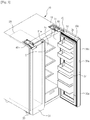
- a refrigerator includes a main body 10, a storage chamber 20 which may be provided in the main body 10 so that a front surface thereof may be opened, a door 30 which may open and close the storage chamber 20, and may include a cold air supplying device which may supply cold air to the storage chamber 20.
- the main body 10 may have approximately a box shape, and may include an inner case 11 which may form the storage chamber 20, an outer case 13 which may be coupled to an outer side of the inner case 11 and may form an exterior, and an insulation material (not shown) which may be provided between the inner case 11 and the outer case 13.
- the inner case 11 may be formed, for example, of a resin material
- the outer case 13 may be formed, for example, of a steel material.
- the cold air supplying device may include a compressor (not shown), a condenser (not shown), an expansion valve (not shown) and an evaporator (not shown), and may circulate a refrigerant and produce cold air using evaporative latent heat.
- the storage chamber 20 may be partitioned, for example, into a left freezer 21 and a right refrigeration chamber 23 by a vertical partition wall 15.
- positions of the freezer 21 and the refrigeration chamber 23 may be switched, and the refrigeration chamber 23 may have a shelf 25 on which food may be put.
- the storage chamber 20 of which the front surface may be opened may be opened and closed by the door 30.
- the door 30 may include a freezer door 31 and a refrigeration chamber door 33 which may open and close the freezer 21 and the refrigeration chamber 23, respectively.
- the freezer door 31 may be rotatably disposed at a front side of the main body 10, and may be provided to be rotated leftward and rightward about a vertical rotational shaft.
- the freezer door 31 may be rotatably supported by an upper hinge 40 and a lower hinge 50 which may be respectively coupled to an upper surface and a lower surface of the main body 10.
- the refrigeration chamber door 33 may also be rotatably disposed at the front side of the main body 10, and may be provided to be rotated leftward and rightward about a vertical rotational shaft.
- the refrigeration chamber door 33 may have an opening part 33c formed to have a slightly smaller size than the refrigeration chamber 23, and a plurality of door guards 37 are provided at the opening part 33c.
- the opening part 33c provided at the refrigeration chamber door 33 may be opened and closed by the external door 35.
- the refrigeration chamber door 33 is referred to as an internal door.
- the internal door 33 may be rotatably supported by a first upper hinge 60 and a first lower hinge 80 which may be respectively coupled to the upper surface and the lower surface of the main body 10.
- the external door 35 is rotatably disposed at a front side of the internal door 33, and may be provided so as to be rotated in the same rotational direction as that of the internal door 33.
- Rotational shafts of the internal door 33 and the external door 35 may be parallel with each other, but may not be coaxial.
- the external door 35 may be rotatably supported by a second upper hinge 70 and a second lower hinge 90 which may be respectively coupled to an upper surface and a lower surface of the internal door 33.
- a handle 31a may be provided at the freezer door 31 in order to allow a user to grasp the handle 31a and then open and close the freezer door 31.
- a first handle 33a and a second handle 35a may also be provided at the internal and external doors 33 and 35, respectively.
- the first and second handles 33a and 35a may be provided to be parallel with each other in a roughly vertical direction and the first handle 33a may be provided above the second handle 35a.
- first and second handles 33a and 35a may have first and second receiving grooves 33b and 35b which may receive a user's hand.
- the first and second receiving grooves 33b and 35b may also be provided to be parallel with each other in the roughly vertical direction.
- the first receiving groove 33b may be disposed over the second receiving groove 35b.
- the user may put his/her hand into the first receiving groove 33b and grasp the first handle 33a, and may also put his/her hand into the second receiving groove 35b and grasp the second handle 35a.
- a handle cover 35c may be formed to extend to an upper side of the second handle 35a and thus may cover the first handle 33a.
- the first handle 33a when seen from a front side, the first handle 33a may be covered by the handle cover 35c and thus may not be exposed.
- the external door 35 may not have the opening part, and may have a roughly flat plate shape so as to open and close the opening part 33c of the internal door 33.
- the refrigeration chamber 23 may be airtightly sealed, and thus the cold air in the refrigeration chamber 23 may be preserved.
- the user may approach at least one door guard 37 and then may store and remove food in and from the at least one door guard 37.
- leakage of the cold air from the refrigeration chamber 23 may be reduced, compared with a state in which the internal door 33 is opened.
- the user may access an inside of the refrigeration chamber 23 and then store and remove food on and from the shelf 25, and may also access the at least one door guard 37 and then store and remove food in and from the at least one door guard 37.
- the food may be stored and removed, as necessary, in various manners, and the leakage of the cold air may be minimized.
- a first gasket 33d may be provided at a rear surface of the internal door 33 so as to possibly maintain an airtight seal between the internal door 33 and the outer case 13 of the main body 10.
- the first gasket 33d may be formed, for example, of a rubber material.
- first gasket 33d may include a first magnet (not shown) so as to attract the outer case 13 formed of the steel material and thus to possibly maintain a closed state of the internal door 33.
- a second gasket 35d may be provided at a rear surface of the external door 35 so as to possibly maintain an airtight seal between the external door 35 and the internal door 33.
- the second gasket 35d may be formed, for example, of a rubber material.
- the second gasket 35d may include a second magnet (not shown) so as to attract a front surface of the internal door 33 formed of the steel material and thus to possibly maintain a closed state of the external door 35.
- the internal and external doors 33 and 35 may be normally maintained in the closed state by magnetic force of the magnets.
- the magnetic force of the first magnet (not shown) of the internal door 33, which attracts the outer case 13 of the main body 10, should be greater than that of the second magnet (not shown) of the external door 35, which attracts the internal door 33.
- the external door 35 when the user pulls the external door 35 by applying force which is greater than the magnetic force of the second magnet (not shown) of the external door 35, which attracts the internal door 33, the external door 35 may be opened, while the internal door 33 is in the closed state.
- the internal door 33 may be opened together by inertial force of the external door 35.
- the internal door 33 when the user grasps the second handle 35a and opens the external door 35, the external door 35 is sufficiently opened and then stopped. At this time, if the rotational inertial force is greater than the magnetic force of the first magnet (not shown) of the internal door 33, which attracts the outer case 13 of the main body 10, the internal door 33 may be undesirably opened.
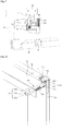
- a refrigerator according to the invention includes an internal door opening prevention device 100 which prevents the internal door 33 from being undesirably opened by the inertial force when the external door 35 is opened.
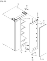
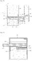
- the internal door opening prevention device 100 includes a stopper 110 which is coupled to a lower portion of the main body 10, a locking part 120 which is rotatably coupled to a lower portion of the internal door 33, a spring 130 which elastically supports the locking part 120, and a cover 140 which covers the locking part 120 so that the locking part 120 is not exposed to an outside.
- the stopper 110 is coupled to the lower portion of the main body 10 by a fastening member B, and may include a hook 111 which may have a shape corresponding to a locking hook 125 of the locking part 120, which will be described later, so as to be locked or unlocked with the locking hook 125.
- the locking part 120 is rotatably coupled to the lower portion of the internal door 33 by a rotational protrusion 143 that is provided at the cover 140, which will be described later, and may include a rotational hole 121 into which the rotational protrusion 143 may be inserted, a contact portion 123 which may be in contact with a protruding part 39 that is coupled to the external door 35, the locking hook 125 which may be rotated according to whether the external door 35 is opened or closed and locked or unlocked with the stopper 110, and a spring coupling portion 127 to which the spring 130 may be coupled.
- the locking part 120 which is rotatably coupled to the lower portion of the internal door 33 may be disposed so that the contact portion 123 may be directed to the external door 35 and the locking hook 125 may be directed to the main body 10.
- the protruding part 39 is coupled to the lower portion of the external door 35 so as to be in contact with the contact portion 123 when the external door 35 is closed, and thus to rotate the locking part 120. Therefore, if the external door 35 is closed, the protruding part 39 may push the contact portion 123, and thus the locking part 120 may be rotated around the rotational protrusion 143 in a counterclockwise direction.
- the locking hook 125 may be provided to have a shape corresponding to the hook 111 of the stopper 110, and may be locked or unlocked with the hook 111 according to whether the external door 35 is opened or closed.
- the spring 130 may be coupled to the spring coupling portion 127 so as to rotate the locking part 120 around the rotational protrusion 143 in a clockwise direction when the external door 35 is opened and contact between the protruding part 39 and the contact portion 123 is released.
- One end of the spring 130 may be coupled to the spring coupling portion 127 of the locking part 120, and the other end may be supported by a spring supporting part 141 of the cover 140, which will be described later.
- the spring 130 When the external door 35 is closed, the spring 130 may be compressed by the locking part 120 which may be rotated around the rotational protrusion 143 in the counterclockwise direction by the protruding part 39 of the external door 35, and thus a compressed force may be stored.
- the spring 130 When the external door 35 is opened, the spring 130 may rotate the locking part 120, which may be released from the contact with the protruding part 39, around the rotational protrusion 143 in the clockwise direction using the compressed force.
- the cover 140 is coupled to the lower portion of the internal door 33 by the fastening member B so as to cover the locking part 120, such that the locking part 120 may not be exposed to the outside.
- the cover 140 may include the spring supporting part 141 which may support the other end of the spring 130, and the rotational protrusion 143 to which the locking part 120 may be rotatably coupled. Parts of front and rear surfaces of the cover 140 may be opened so that the locking part 120 may be rotated forward and backward around the rotational protrusion 143.
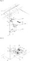
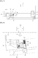
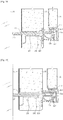
- FIGS. 7 to 9 An operation of the internal door opening prevention device which allows or prevents opening of the internal door according to whether the external door is opened or closed will be described with reference to FIGS. 7 to 9 .
- the protruding part 39 provided at the external door 35 is in contact with the contact portion 123 of the locking part 120 and may push the contact portion 123.
- the locking part 120 may be rotated around the rotational protrusion 143 in the counterclockwise direction, and the locking hook 125 may be unlocked with the hook 111 of the stopper 110.
- the locking part 120 may be rotated around the rotational protrusion 143 in the counterclockwise direction, the spring 130 may be compressed by the locking part 120, and the compressed force may be stored.
- the internal door 33 is in a state in which it may be freely rotated from the main body 10, and thus the internal door 33 may be opened, as illustrated in FIG. 8 .
- the protruding part 39 provided at the external door 35 is released from the contact with the contact portion 123 of the locking part 120, and the locking part 120 may be rotated around the rotational protrusion 143 in the clockwise direction by the compressed force of the spring 130.
- the locking hook 125 is in a locked state with the hook 111 of the stopper 110.
- the internal door 33 is locked with the main body 10, and thus the internal door 33 may not be opened, even when the external door 35 is opened.
- the internal door opening prevention device 100 enables the internal door 33 to be freely rotated from the main body 10 and thus allows the internal door 33 to be opened.
- the internal door opening prevention device 100 enables the internal door 33 not to be freely rotated from the main body 10 and thus prevents the internal door 33 from being opened.
- the refrigerator according to the invention may further include an external door opening prevention device 200 which may prevent the external door 35 from being undesirably opened by the inertial force when the internal door 33 is opened.
- the internal door 33 may be sufficiently opened and then stopped. At this time, if the rotational inertial force is greater than the magnetic force of the second magnet (not shown) of the external door 35, which attracts the internal door 33, the external door 35 may be undesirably opened.
- the external door opening prevention device 200 may be coupled to an upper portion of the internal door 33, and may include a stopper 210 which may be coupled to an upper portion of the handle cover 35c that may be disposed at the upper portion of the second handle 35a of the external door 35, a locking part 220 which may be coupled to an upper portion of the first handle 33a of the internal door 33, a housing 230 which may be built in the upper portion of the internal door 33, an operation bar 240 which may be received in the housing 230 so as to be linearly moved forward and backward, and a spring 250 which may elastically support the operation bar 240.
- a stopper 210 which may be coupled to an upper portion of the handle cover 35c that may be disposed at the upper portion of the second handle 35a of the external door 35
- a locking part 220 which may be coupled to an upper portion of the first handle 33a of the internal door 33
- a housing 230 which may be built in the upper portion of the internal door 33
- an operation bar 240 which may be received in the housing
- the stopper 210 may be coupled to the upper portion of the handle cover 35c that may be disposed at the upper portion of the second handle 35a of the external door 35, and may include a hooking portion 211 which may be locked or unlocked with the locking part 220.
- the locking part 220 is coupled to the upper portion of the first handle 33a of the internal door 33, and may include a locking hook 221 which may be locked or unlocked with the hooking portion 211 of the stopper 210, an elastic portion 223 which may be elastically deformed by a linear movement of the operation bar 240, and first and second coupling holes 225 and 227 into which first and second coupling protrusions 33e and 33f that may be provided at the first handle 33a of the internal door 33 may be respectively inserted.
- the elastic portion 223 may be provided to be elastically deformed left and right by the operation bar 240, and the locking hook 221 may be provided at one side of the elastic portion 223 so as to be locked or unlocked with the hooking portion 211.
- the first handle 33a may have a through-hole 33g through which the locking hook 221 may pass, such that the locking hook 221 may be locked or unlocked with the hooking portion 211.
- the housing 230 may be built in the upper portion of the internal door 33, and may include a receiving groove 231 in which the operation bar 240 may be received to be linearly moved forward and backward, and a spring supporting portion 233 which may support the spring 250.
- the operation bar 240 may be received in the receiving groove 231 of the housing 230 so as to be linearly moved forward and backward according to whether the internal door 33 is opened or closed.
- the operation bar 240 may include a head portion 241 which may be in contact with the main body 10 when the internal door 33 is closed, a body portion 243 which may be linearly moved forward and backward according to whether the internal door 33 is opened or closed so as to elastically deform the elastic portion 223 of the locking part 220, and a spring coupling portion 245 to which the spring 250 may be coupled.
- the head portion 241 may be in contact with the main body 10 and may be linearly moved forward in the receiving groove 231 of the housing 230. While the operation bar 240 is moved forward, the body portion 243 may be in contact with the elastic portion 223 of the locking part 220 and may elastically deform the elastic portion 223, and thus the locking hook 221 may be unlocked with the hooking portion 211 of the stopper 210.
- the spring 250 coupled to the operation bar 240 may be compressed and thus a compressed force is stored.
- the external door 35 may be freely rotated.
- the head portion 241 may be released from the contact with the main body 10 and may be linearly moved backward by the spring 250 having the compressed force. While the operation bar 240 is moved backward, the body portion 243 may be released from the contact with the elastic portion 223 of the locking part 220, and the elastic portion 223 may be restored to its original shape, and thus the locking hook 221 may be locked with the hooking portion 211 of the stopper 210.
- the external door 35 may be restricted by the internal door 33 so as not to be freely rotated.
- One end of the spring 250 may be coupled to the spring coupling portion 245 of the operation bar 240, and the other end may be supported by the spring supporting portion 233 of the housing 230.
- the spring 250 When the internal door 33 is closed, the spring 250 may be in contact with the main body 10 and may be compressed by the operation bar 240 which may be linearly moved forward, and thus the compressed force may be stored. When the internal door 33 is opened, the spring 250 may enable the operation bar 240 released from the contact with the main body 10 to be linearly moved backward by the stored compressed force.
- the body portion 243 of the operation bar 240 may not be in contact with the elastic portion 223 of the locking part 220, and thus the locking hook 221 may be locked with the hooking portion 211 of the stopper 210, and the external door 35 may be fixed to the internal door 33 so as not to be freely rotated.
- the head portion 241 of the operation bar 240 may be in contact with the main body 10, and the operation bar 240 may be linearly moved forward.
- the body portion 243 may be in contact with the elastic portion 223 of the locking part 220, and the elastic portion 223 may be elastically deformed.
- the locking hook 221 provided at one side of the elastic portion 223 may be unlocked with the hooking portion 211 of the stopper 210, and the external door 35 may be in a state in which it can be freely rotated, and thus the external door 35 may be opened, as illustrated in FIG. 12 .
- the spring 250 may be compressed by the operation bar 240 which may be linearly moved forward.
- the head portion 241 of the operation bar 240 may be released from the contact with the main body 10, as illustrated in FIG. 14 , and the operation bar 240 may be linearly moved backward by the spring 250 having the stored compressed force.
- the body portion 243 may be linearly moved backward and released from the contact with the elastic portion 223, and the elastic portion 223 may be restored to its original shape, and thus the locking hook 221 may be locked again with the hooking portion 211 of the stopper 210.
Landscapes
- Engineering & Computer Science (AREA)
- Mechanical Engineering (AREA)
- Physics & Mathematics (AREA)
- Thermal Sciences (AREA)
- Chemical & Material Sciences (AREA)
- Combustion & Propulsion (AREA)
- General Engineering & Computer Science (AREA)
- Refrigerator Housings (AREA)
Claims (7)
- Kühlschrank, umfassend:einen Hauptkörper (10);eine Aufbewahrungskammer (23), die in dem Hauptkörper (10) so vorgesehen ist, dass eine vordere Oberfläche davon geöffnet ist;eine innere Tür (33), die drehbar an einer vorderen Oberfläche des Hauptkörpers (10) vorgesehen ist, um die Aufbewahrungskammer (23) zu öffnen und zu schließen, und einen Öffnungsteil (33c) aufweist, in dem eine Mehrzahl von Türfächern (37) vorgesehen sind;eine äußere Tür (35), die drehbar an einer vorderen Oberfläche der inneren Tür (33) vorgesehen ist, um den Öffnungsteil (33c) zu öffnen und zu schließen; undeine Innentür-Öffnungsverhinderungsvorrichtung (100), um das Öffnen der inneren Tür (33) zuzulassen oder zu verhindern, je nachdem, ob die äußere Tür (35) geöffnet oder geschlossen ist,wobeidie Innentür-Öffnungsverhinderungsvorrichtung (100) umfasst:einen Anschlag (110), der an einen unteren Abschnitt des Hauptkörpers (10) gekoppelt ist;ein Verriegelungsteil (120), der drehbar an einen unteren Abschnitt der inneren Tür (33) gekoppelt ist und je nachdem, ob die äußere Tür (35) geöffnet oder geschlossen ist, gedreht wird, um mit dem Anschlag (110) verriegelt und entriegelt zu werden;eine Feder (130), die dazu ausgestaltet ist, den Verriegelungsteil (120) elastisch zu stützen, undeine Abdeckung (140), die dazu ausgestaltet ist, das Verriegelungsteil (120) abzudecken, um zu verhindern, dass das Verriegelungsteil (120) einer Außenseite ausgesetzt wird,wobei der Kühlschrank dadurch gekennzeichnet ist, dass die Abdeckung einen drehbaren Vorsprung (143) aufweist, an den das Verriegelungsteil (120) drehbar gekoppelt ist, wobei der Anschlag (110) und die Abdeckung (140) jeweils durch Befestigungselemente (B) an den unteren Abschnitt des Hauptkörpers (10) und den unteren Abschnitt der inneren Tür (33) gekoppelt sind,und dassein Vorsprungsteil (39) an einen unteren Abschnitt der äußeren Tür (35) gekoppelt ist, um in Kontakt mit dem Verriegelungsteil (120) zu sein und damit den Verriegelungsteil (120) zu drehen, um von dem Anschlag (110) entriegelt zu werden, wenn die äußere Tür (35) geschlossen ist, damit die Feder (130) mit dem Verriegelungsteil (120) komprimiert wird, und eine Kompressionskraft der Feder (130) speichert, während, wenn die äußere Tür (35) geöffnet ist, ein Lösen des Vorsprungsteils (39) aus dem Kontakt mit dem unteren Abschnitt der äußeren Tür (35) eine Drehung des Verriegelungsteils (120) infolge der Kompressionskraft der Feder (130) auslöst, wodurch das Verriegelungsteil (120) mit dem Anschlag (110) verriegelt werden kann.
- Kühlschrank nach Anspruch 1, wobei die Innentür-Öffnungsverhinderungsvorrichtung (100) zulässt, dass die innere Tür (33) geöffnet wird, wenn die äußere Tür (35) geschlossen ist, und verhindert, dass die innere Tür (33) geöffnet wird, wenn die äußere Tür (35) geöffnet ist.
- Kühlschrank nach Anspruch 1, wobei das Verriegelungsteil (120) durch den drehbaren Vorsprung (143) drehbar an den unteren Abschnitt der inneren Tür (33) gekoppelt ist, und umfasst:ein drehbares Loch (121), in das der drehbare Vorsprung (143) eingesetzt wird;ein Kontaktabschnitt (123), der in Kontakt mit dem Vorsprungsteil (39) steht;ein Verriegelungshaken (125), der, je nachdem, ob die äußere Tür (35) geöffnet oder geschlossen ist, gedreht wird und mit dem Anschlag (110) entriegelt wird; undein Federkopplungsabschnitt (127), an den die Feder (130) gekoppelt ist.
- Kühlschrank nach Anspruch 3, wobei der Anschlag (110) einen Haken (111) umfasst, der eine Form aufweist, die der des Verriegelungshakens (125) entspricht, sodass der Verriegelungshaken (125) je nach Drehung des Verriegelungshakens (125) verriegelt und entriegelt wird.
- Kühlschrank nach Anspruch 4, wobei Teile von vorderen und hinteren Oberflächen der Abdeckung (140) geöffnet sind, sodass das Verriegelungsteil (120) vorwärts und rückwärts um den drehbaren Vorsprung (143) gedreht wird, und die Abdeckung (140) einen Federstützabschnitt umfasst, der ein Ende der Feder (130) stützt, dessen anderes Ende an den Federkupplungsabschnitt (127) gekoppelt ist.
- Kühlschrank nach Anspruch 5, wobei, wenn die äußere Tür (35) geschlossen ist, das Vorsprungsteil (39) in Kontakt mit dem Kontaktabschnitt (123) steht, sodass das Verriegelungsteil (120) um den drehbaren Vorsprung (143) in eine Richtung entgegen dem Uhrzeigersinn gedreht wird, und wenn das Verriegelungsteil (120) um den drehbaren Vorsprung (143) in die Richtung entgegen dem Uhrzeigersinn gedreht wird, der Verriegelungshaken (125) mit dem Anschlag (110) entriegelt wird und zugelassen wird, dass die innere Tür (33) geöffnet wird.
- Kühlschrank nach Anspruch 6, wobei, wenn die äußere Tür (35) geöffnet ist, das Vorsprungsteil (39) aus dem Kontakt mit dem Kontaktabschnitt (123) gelöst wird, und das Verriegelungsteil (120) um den drehbaren Vorsprung (143) durch die Feder (130) in eine Richtung im Uhrzeigersinn gedreht wird, und wenn das Verriegelungsteil (120) um den drehbaren Vorsprung (143) in die Richtung im Uhrzeigersinn gedreht wird, der Verriegelungshaken (125) mit dem Anschlag (110) verriegelt wird und verhindert wird, dass die innere Tür (33) geöffnet wird.
Applications Claiming Priority (2)
| Application Number | Priority Date | Filing Date | Title |
|---|---|---|---|
| KR1020130139646A KR102218309B1 (ko) | 2013-11-18 | 2013-11-18 | 냉장고 |
| PCT/KR2014/011006 WO2015072793A1 (en) | 2013-11-18 | 2014-11-17 | Refrigerator |
Publications (3)
| Publication Number | Publication Date |
|---|---|
| EP3071909A1 EP3071909A1 (de) | 2016-09-28 |
| EP3071909A4 EP3071909A4 (de) | 2017-07-26 |
| EP3071909B1 true EP3071909B1 (de) | 2020-01-15 |
Family
ID=53057661
Family Applications (1)
| Application Number | Title | Priority Date | Filing Date |
|---|---|---|---|
| EP14861962.0A Active EP3071909B1 (de) | 2013-11-18 | 2014-11-17 | Kühlschrank |
Country Status (8)
| Country | Link |
|---|---|
| US (1) | US9482463B2 (de) |
| EP (1) | EP3071909B1 (de) |
| KR (1) | KR102218309B1 (de) |
| CN (1) | CN105723170B (de) |
| AU (1) | AU2014349336B2 (de) |
| BR (1) | BR112016002943A2 (de) |
| CA (1) | CA2919836C (de) |
| WO (1) | WO2015072793A1 (de) |
Cited By (1)
| Publication number | Priority date | Publication date | Assignee | Title |
|---|---|---|---|---|
| EP4621328A1 (de) * | 2024-03-21 | 2025-09-24 | Beko Europe Management S.r.l. | Anti-türstoss-kit für eine kühlvorrichtung und verfahren zur verhinderung von türstoss in einer kühlvorrichtung |
Families Citing this family (53)
| Publication number | Priority date | Publication date | Assignee | Title |
|---|---|---|---|---|
| US10188098B2 (en) * | 2009-05-12 | 2019-01-29 | Reflect Scientific Inc. | Extremely fast freezing, low-temperature blast freezer |
| US9140481B2 (en) | 2012-04-02 | 2015-09-22 | Whirlpool Corporation | Folded vacuum insulated structure |
| US9221210B2 (en) | 2012-04-11 | 2015-12-29 | Whirlpool Corporation | Method to create vacuum insulated cabinets for refrigerators |
| EP3008408B1 (de) * | 2013-06-14 | 2021-02-24 | LG Electronics Inc. | Kühlschrank |
| WO2014200315A1 (en) * | 2013-06-14 | 2014-12-18 | Lg Electronics Inc. | Refrigerator |
| KR101622228B1 (ko) | 2014-02-21 | 2016-05-18 | 엘지전자 주식회사 | 냉장고 |
| US9689604B2 (en) | 2014-02-24 | 2017-06-27 | Whirlpool Corporation | Multi-section core vacuum insulation panels with hybrid barrier film envelope |
| US10052819B2 (en) | 2014-02-24 | 2018-08-21 | Whirlpool Corporation | Vacuum packaged 3D vacuum insulated door structure and method therefor using a tooling fixture |
| US9476633B2 (en) | 2015-03-02 | 2016-10-25 | Whirlpool Corporation | 3D vacuum panel and a folding approach to create the 3D vacuum panel from a 2D vacuum panel of non-uniform thickness |
| US10161669B2 (en) | 2015-03-05 | 2018-12-25 | Whirlpool Corporation | Attachment arrangement for vacuum insulated door |
| US9897370B2 (en) | 2015-03-11 | 2018-02-20 | Whirlpool Corporation | Self-contained pantry box system for insertion into an appliance |
| US9441779B1 (en) | 2015-07-01 | 2016-09-13 | Whirlpool Corporation | Split hybrid insulation structure for an appliance |
| KR101758284B1 (ko) * | 2015-09-11 | 2017-07-14 | 엘지전자 주식회사 | 냉장고 |
| KR102499268B1 (ko) * | 2015-12-02 | 2023-02-13 | 삼성전자주식회사 | 냉장고 |
| US11052579B2 (en) | 2015-12-08 | 2021-07-06 | Whirlpool Corporation | Method for preparing a densified insulation material for use in appliance insulated structure |
| US10422573B2 (en) | 2015-12-08 | 2019-09-24 | Whirlpool Corporation | Insulation structure for an appliance having a uniformly mixed multi-component insulation material, and a method for even distribution of material combinations therein |
| US12508751B2 (en) | 2015-12-08 | 2025-12-30 | Whirlpool Corporation | Insulation compaction device and method for forming an insulated structure for an appliance |
| US10222116B2 (en) | 2015-12-08 | 2019-03-05 | Whirlpool Corporation | Method and apparatus for forming a vacuum insulated structure for an appliance having a pressing mechanism incorporated within an insulation delivery system |
| US10041724B2 (en) | 2015-12-08 | 2018-08-07 | Whirlpool Corporation | Methods for dispensing and compacting insulation materials into a vacuum sealed structure |
| US10429125B2 (en) | 2015-12-08 | 2019-10-01 | Whirlpool Corporation | Insulation structure for an appliance having a uniformly mixed multi-component insulation material, and a method for even distribution of material combinations therein |
| US11994336B2 (en) | 2015-12-09 | 2024-05-28 | Whirlpool Corporation | Vacuum insulated structure with thermal bridge breaker with heat loop |
| US10808987B2 (en) | 2015-12-09 | 2020-10-20 | Whirlpool Corporation | Vacuum insulation structures with multiple insulators |
| KR102391404B1 (ko) | 2015-12-17 | 2022-04-27 | 엘지전자 주식회사 | 냉장고 |
| KR102391409B1 (ko) | 2015-12-17 | 2022-04-27 | 엘지전자 주식회사 | 냉장고 |
| US10422569B2 (en) | 2015-12-21 | 2019-09-24 | Whirlpool Corporation | Vacuum insulated door construction |
| US10087658B2 (en) * | 2015-12-22 | 2018-10-02 | Whirlpool Corporation | Refrigerator door-in-door latch |
| US10018406B2 (en) | 2015-12-28 | 2018-07-10 | Whirlpool Corporation | Multi-layer gas barrier materials for vacuum insulated structure |
| US10610985B2 (en) | 2015-12-28 | 2020-04-07 | Whirlpool Corporation | Multilayer barrier materials with PVD or plasma coating for vacuum insulated structure |
| US10030905B2 (en) | 2015-12-29 | 2018-07-24 | Whirlpool Corporation | Method of fabricating a vacuum insulated appliance structure |
| US10807298B2 (en) | 2015-12-29 | 2020-10-20 | Whirlpool Corporation | Molded gas barrier parts for vacuum insulated structure |
| US11247369B2 (en) | 2015-12-30 | 2022-02-15 | Whirlpool Corporation | Method of fabricating 3D vacuum insulated refrigerator structure having core material |
| EP3443284B1 (de) | 2016-04-15 | 2020-11-18 | Whirlpool Corporation | Vakuumisolierte kühlstruktur mit dreidimensionalen eigenschaften |
| US10712080B2 (en) | 2016-04-15 | 2020-07-14 | Whirlpool Corporation | Vacuum insulated refrigerator cabinet |
| KR102567513B1 (ko) | 2016-06-08 | 2023-08-17 | 삼성전자주식회사 | 냉장고 |
| US11320193B2 (en) | 2016-07-26 | 2022-05-03 | Whirlpool Corporation | Vacuum insulated structure trim breaker |
| WO2018034665A1 (en) | 2016-08-18 | 2018-02-22 | Whirlpool Corporation | Machine compartment for a vacuum insulated structure |
| EP3526531A4 (de) | 2016-10-11 | 2020-06-17 | Whirlpool Corporation | Strukturschrank für ein gerät mit einheitlichen metallischen kästen |
| WO2018101954A1 (en) | 2016-12-02 | 2018-06-07 | Whirlpool Corporation | Hinge support assembly |
| US10352613B2 (en) | 2016-12-05 | 2019-07-16 | Whirlpool Corporation | Pigmented monolayer liner for appliances and methods of making the same |
| DE102017109263B4 (de) * | 2017-04-28 | 2019-06-06 | Binder Gmbh | Laborschrank |
| DE102017109262A1 (de) * | 2017-04-28 | 2018-10-31 | Binder Gmbh | Laborschrank |
| KR101894883B1 (ko) * | 2017-06-02 | 2018-10-04 | 엘지전자 주식회사 | 의류처리장치 |
| US11078697B2 (en) | 2017-08-28 | 2021-08-03 | Samsung Electronics Co., Ltd. | Home appliance |
| KR102527312B1 (ko) * | 2017-08-28 | 2023-05-03 | 삼성전자주식회사 | 가전기기 |
| US10907888B2 (en) | 2018-06-25 | 2021-02-02 | Whirlpool Corporation | Hybrid pigmented hot stitched color liner system |
| KR20200009356A (ko) * | 2018-07-18 | 2020-01-30 | 주식회사 위니아대우 | 도어 개폐 장치를 포함하는 냉장고 |
| US11359414B2 (en) | 2019-01-24 | 2022-06-14 | Whirlpool Corporation | Latch assembly |
| US10907891B2 (en) | 2019-02-18 | 2021-02-02 | Whirlpool Corporation | Trim breaker for a structural cabinet that incorporates a structural glass contact surface |
| KR102705983B1 (ko) * | 2019-04-26 | 2024-09-12 | 엘지전자 주식회사 | 냉장고 |
| KR102723870B1 (ko) * | 2019-05-10 | 2024-10-29 | 엘지전자 주식회사 | 스토퍼 및 이를 포함하는 스토퍼조립체 |
| US12070924B2 (en) | 2020-07-27 | 2024-08-27 | Whirlpool Corporation | Appliance liner having natural fibers |
| US11668513B2 (en) * | 2020-12-01 | 2023-06-06 | Electrolux Home Products, Inc. | Staged access door for a home appliance |
| KR102473632B1 (ko) * | 2021-07-21 | 2022-12-05 | 주식회사 아이원이노텍 | 도어 개폐장치 |
Family Cites Families (11)
| Publication number | Priority date | Publication date | Assignee | Title |
|---|---|---|---|---|
| US2942438A (en) * | 1955-11-23 | 1960-06-28 | Gen Motors Corp | Refrigerator |
| US2945733A (en) * | 1956-10-26 | 1960-07-19 | John P Malia | Compartmentalized refrigerator |
| US3086830A (en) * | 1960-06-09 | 1963-04-23 | Malia John Peter | Compartmentalized refrigerator |
| CA1126785A (en) * | 1978-10-13 | 1982-06-29 | Jose Massana Canals | Personal security door arrangement |
| JP2000249462A (ja) | 1999-02-26 | 2000-09-14 | Aiwa Co Ltd | 冷蔵庫 |
| JP3732689B2 (ja) * | 1999-10-21 | 2006-01-05 | 株式会社東芝 | 貯蔵庫開扉装置 |
| JP2004211977A (ja) | 2003-01-06 | 2004-07-29 | Sanyo Electric Co Ltd | 内扉付き貯蔵庫 |
| CN102116554A (zh) | 2010-01-04 | 2011-07-06 | Lg电子株式会社 | 电冰箱 |
| KR101768698B1 (ko) | 2010-12-07 | 2017-08-17 | 엘지전자 주식회사 | 냉장고용 이중 도어 개폐 장치 |
| JP2013053843A (ja) * | 2011-08-31 | 2013-03-21 | Lg Electronics Inc | 冷蔵庫 |
| EP2613112B1 (de) * | 2012-01-03 | 2019-10-30 | LG Electronics, Inc. | Kühlschrank mit Lagerungsbehälter |
-
2013
- 2013-11-18 KR KR1020130139646A patent/KR102218309B1/ko not_active Expired - Fee Related
-
2014
- 2014-09-03 US US14/476,220 patent/US9482463B2/en not_active Expired - Fee Related
- 2014-11-17 AU AU2014349336A patent/AU2014349336B2/en not_active Ceased
- 2014-11-17 EP EP14861962.0A patent/EP3071909B1/de active Active
- 2014-11-17 CA CA2919836A patent/CA2919836C/en not_active Expired - Fee Related
- 2014-11-17 BR BR112016002943A patent/BR112016002943A2/pt not_active Application Discontinuation
- 2014-11-17 WO PCT/KR2014/011006 patent/WO2015072793A1/en not_active Ceased
- 2014-11-17 CN CN201480062225.8A patent/CN105723170B/zh not_active Expired - Fee Related
Non-Patent Citations (1)
| Title |
|---|
| None * |
Cited By (1)
| Publication number | Priority date | Publication date | Assignee | Title |
|---|---|---|---|---|
| EP4621328A1 (de) * | 2024-03-21 | 2025-09-24 | Beko Europe Management S.r.l. | Anti-türstoss-kit für eine kühlvorrichtung und verfahren zur verhinderung von türstoss in einer kühlvorrichtung |
Also Published As
| Publication number | Publication date |
|---|---|
| BR112016002943A2 (pt) | 2017-08-01 |
| EP3071909A1 (de) | 2016-09-28 |
| KR102218309B1 (ko) | 2021-02-22 |
| CA2919836A1 (en) | 2015-05-21 |
| EP3071909A4 (de) | 2017-07-26 |
| AU2014349336B2 (en) | 2016-11-17 |
| CA2919836C (en) | 2018-05-15 |
| CN105723170B (zh) | 2019-01-29 |
| WO2015072793A1 (en) | 2015-05-21 |
| KR20150056955A (ko) | 2015-05-28 |
| AU2014349336A1 (en) | 2016-02-18 |
| CN105723170A (zh) | 2016-06-29 |
| US20150137674A1 (en) | 2015-05-21 |
| US9482463B2 (en) | 2016-11-01 |
Similar Documents
| Publication | Publication Date | Title |
|---|---|---|
| EP3071909B1 (de) | Kühlschrank | |
| KR101860718B1 (ko) | 이중 도어를 갖는 냉장고 | |
| US10054360B2 (en) | Refrigerator | |
| RU2484392C1 (ru) | Холодильник | |
| EP3255363B1 (de) | Kühlschrank | |
| US8973392B2 (en) | Refrigerator | |
| CN100523675C (zh) | 电冰箱 | |
| KR20140104640A (ko) | 이중 도어를 갖는 냉장고 | |
| KR101697112B1 (ko) | 이중 도어를 갖는 냉장고 | |
| EP3150946B1 (de) | Kühlschrank mit verriegelungsvorrichtung für Eiskübel und Verfahren zur Installation der Verriegelungsvorrichtung für den Eiskübel | |
| KR20130105543A (ko) | 냉장고 | |
| KR20130105065A (ko) | 냉장고 | |
| KR102567530B1 (ko) | 냉장고 | |
| CN106839614A (zh) | 门引导组件及具有门引导组件的冰箱 | |
| US9995077B2 (en) | Door holding apparatus and refrigerator having the same | |
| KR20140104639A (ko) | 이중 도어를 갖는 냉장고 | |
| KR20130101904A (ko) | 냉장고의 밀폐룸 | |
| EP4664040A1 (de) | Kühlschrank | |
| KR20070012870A (ko) | 냉장고 | |
| KR200232338Y1 (ko) | 냉장고의열쇠장치 | |
| JP2006177624A (ja) | 冷蔵庫 | |
| KR19990049554A (ko) | 냉장실 도어에 와인포켓과 와인도어가 형성된냉장고 | |
| KR20100046546A (ko) | 냉장고 | |
| KR20090102235A (ko) | 틈새보정기능을 구비한 냉장고 |
Legal Events
| Date | Code | Title | Description |
|---|---|---|---|
| PUAI | Public reference made under article 153(3) epc to a published international application that has entered the european phase |
Free format text: ORIGINAL CODE: 0009012 |
|
| 17P | Request for examination filed |
Effective date: 20160215 |
|
| AK | Designated contracting states |
Kind code of ref document: A1 Designated state(s): AL AT BE BG CH CY CZ DE DK EE ES FI FR GB GR HR HU IE IS IT LI LT LU LV MC MK MT NL NO PL PT RO RS SE SI SK SM TR |
|
| AX | Request for extension of the european patent |
Extension state: BA ME |
|
| DAX | Request for extension of the european patent (deleted) | ||
| REG | Reference to a national code |
Ref country code: DE Ref legal event code: R079 Ref document number: 602014060180 Country of ref document: DE Free format text: PREVIOUS MAIN CLASS: F25D0023020000 Ipc: F25D0023040000 |
|
| A4 | Supplementary search report drawn up and despatched |
Effective date: 20170626 |
|
| RIC1 | Information provided on ipc code assigned before grant |
Ipc: F25D 23/02 20060101ALI20170620BHEP Ipc: E05D 11/06 20060101ALI20170620BHEP Ipc: F25D 23/04 20060101AFI20170620BHEP Ipc: E05D 7/081 20060101ALI20170620BHEP Ipc: E05D 11/08 20060101ALI20170620BHEP Ipc: E05D 7/00 20060101ALI20170620BHEP Ipc: E05B 65/00 20060101ALI20170620BHEP Ipc: E05C 7/02 20060101ALI20170620BHEP Ipc: E05B 85/26 20140101ALI20170620BHEP |
|
| GRAP | Despatch of communication of intention to grant a patent |
Free format text: ORIGINAL CODE: EPIDOSNIGR1 |
|
| STAA | Information on the status of an ep patent application or granted ep patent |
Free format text: STATUS: GRANT OF PATENT IS INTENDED |
|
| INTG | Intention to grant announced |
Effective date: 20190724 |
|
| GRAS | Grant fee paid |
Free format text: ORIGINAL CODE: EPIDOSNIGR3 |
|
| GRAA | (expected) grant |
Free format text: ORIGINAL CODE: 0009210 |
|
| STAA | Information on the status of an ep patent application or granted ep patent |
Free format text: STATUS: THE PATENT HAS BEEN GRANTED |
|
| AK | Designated contracting states |
Kind code of ref document: B1 Designated state(s): AL AT BE BG CH CY CZ DE DK EE ES FI FR GB GR HR HU IE IS IT LI LT LU LV MC MK MT NL NO PL PT RO RS SE SI SK SM TR |
|
| REG | Reference to a national code |
Ref country code: CH Ref legal event code: EP Ref country code: GB Ref legal event code: FG4D |
|
| REG | Reference to a national code |
Ref country code: IE Ref legal event code: FG4D |
|
| REG | Reference to a national code |
Ref country code: DE Ref legal event code: R096 Ref document number: 602014060180 Country of ref document: DE |
|
| REG | Reference to a national code |
Ref country code: AT Ref legal event code: REF Ref document number: 1225508 Country of ref document: AT Kind code of ref document: T Effective date: 20200215 |
|
| REG | Reference to a national code |
Ref country code: NL Ref legal event code: MP Effective date: 20200115 |
|
| REG | Reference to a national code |
Ref country code: LT Ref legal event code: MG4D |
|
| PG25 | Lapsed in a contracting state [announced via postgrant information from national office to epo] |
Ref country code: NO Free format text: LAPSE BECAUSE OF FAILURE TO SUBMIT A TRANSLATION OF THE DESCRIPTION OR TO PAY THE FEE WITHIN THE PRESCRIBED TIME-LIMIT Effective date: 20200415 Ref country code: FI Free format text: LAPSE BECAUSE OF FAILURE TO SUBMIT A TRANSLATION OF THE DESCRIPTION OR TO PAY THE FEE WITHIN THE PRESCRIBED TIME-LIMIT Effective date: 20200115 Ref country code: RS Free format text: LAPSE BECAUSE OF FAILURE TO SUBMIT A TRANSLATION OF THE DESCRIPTION OR TO PAY THE FEE WITHIN THE PRESCRIBED TIME-LIMIT Effective date: 20200115 Ref country code: PT Free format text: LAPSE BECAUSE OF FAILURE TO SUBMIT A TRANSLATION OF THE DESCRIPTION OR TO PAY THE FEE WITHIN THE PRESCRIBED TIME-LIMIT Effective date: 20200607 Ref country code: NL Free format text: LAPSE BECAUSE OF FAILURE TO SUBMIT A TRANSLATION OF THE DESCRIPTION OR TO PAY THE FEE WITHIN THE PRESCRIBED TIME-LIMIT Effective date: 20200115 |
|
| PG25 | Lapsed in a contracting state [announced via postgrant information from national office to epo] |
Ref country code: BG Free format text: LAPSE BECAUSE OF FAILURE TO SUBMIT A TRANSLATION OF THE DESCRIPTION OR TO PAY THE FEE WITHIN THE PRESCRIBED TIME-LIMIT Effective date: 20200415 Ref country code: SE Free format text: LAPSE BECAUSE OF FAILURE TO SUBMIT A TRANSLATION OF THE DESCRIPTION OR TO PAY THE FEE WITHIN THE PRESCRIBED TIME-LIMIT Effective date: 20200115 Ref country code: LV Free format text: LAPSE BECAUSE OF FAILURE TO SUBMIT A TRANSLATION OF THE DESCRIPTION OR TO PAY THE FEE WITHIN THE PRESCRIBED TIME-LIMIT Effective date: 20200115 Ref country code: IS Free format text: LAPSE BECAUSE OF FAILURE TO SUBMIT A TRANSLATION OF THE DESCRIPTION OR TO PAY THE FEE WITHIN THE PRESCRIBED TIME-LIMIT Effective date: 20200515 Ref country code: HR Free format text: LAPSE BECAUSE OF FAILURE TO SUBMIT A TRANSLATION OF THE DESCRIPTION OR TO PAY THE FEE WITHIN THE PRESCRIBED TIME-LIMIT Effective date: 20200115 Ref country code: GR Free format text: LAPSE BECAUSE OF FAILURE TO SUBMIT A TRANSLATION OF THE DESCRIPTION OR TO PAY THE FEE WITHIN THE PRESCRIBED TIME-LIMIT Effective date: 20200416 |
|
| REG | Reference to a national code |
Ref country code: DE Ref legal event code: R097 Ref document number: 602014060180 Country of ref document: DE |
|
| PG25 | Lapsed in a contracting state [announced via postgrant information from national office to epo] |
Ref country code: SK Free format text: LAPSE BECAUSE OF FAILURE TO SUBMIT A TRANSLATION OF THE DESCRIPTION OR TO PAY THE FEE WITHIN THE PRESCRIBED TIME-LIMIT Effective date: 20200115 Ref country code: DK Free format text: LAPSE BECAUSE OF FAILURE TO SUBMIT A TRANSLATION OF THE DESCRIPTION OR TO PAY THE FEE WITHIN THE PRESCRIBED TIME-LIMIT Effective date: 20200115 Ref country code: SM Free format text: LAPSE BECAUSE OF FAILURE TO SUBMIT A TRANSLATION OF THE DESCRIPTION OR TO PAY THE FEE WITHIN THE PRESCRIBED TIME-LIMIT Effective date: 20200115 Ref country code: EE Free format text: LAPSE BECAUSE OF FAILURE TO SUBMIT A TRANSLATION OF THE DESCRIPTION OR TO PAY THE FEE WITHIN THE PRESCRIBED TIME-LIMIT Effective date: 20200115 Ref country code: RO Free format text: LAPSE BECAUSE OF FAILURE TO SUBMIT A TRANSLATION OF THE DESCRIPTION OR TO PAY THE FEE WITHIN THE PRESCRIBED TIME-LIMIT Effective date: 20200115 Ref country code: CZ Free format text: LAPSE BECAUSE OF FAILURE TO SUBMIT A TRANSLATION OF THE DESCRIPTION OR TO PAY THE FEE WITHIN THE PRESCRIBED TIME-LIMIT Effective date: 20200115 Ref country code: ES Free format text: LAPSE BECAUSE OF FAILURE TO SUBMIT A TRANSLATION OF THE DESCRIPTION OR TO PAY THE FEE WITHIN THE PRESCRIBED TIME-LIMIT Effective date: 20200115 Ref country code: LT Free format text: LAPSE BECAUSE OF FAILURE TO SUBMIT A TRANSLATION OF THE DESCRIPTION OR TO PAY THE FEE WITHIN THE PRESCRIBED TIME-LIMIT Effective date: 20200115 |
|
| REG | Reference to a national code |
Ref country code: AT Ref legal event code: MK05 Ref document number: 1225508 Country of ref document: AT Kind code of ref document: T Effective date: 20200115 |
|
| PLBE | No opposition filed within time limit |
Free format text: ORIGINAL CODE: 0009261 |
|
| STAA | Information on the status of an ep patent application or granted ep patent |
Free format text: STATUS: NO OPPOSITION FILED WITHIN TIME LIMIT |
|
| 26N | No opposition filed |
Effective date: 20201016 |
|
| PG25 | Lapsed in a contracting state [announced via postgrant information from national office to epo] |
Ref country code: IT Free format text: LAPSE BECAUSE OF FAILURE TO SUBMIT A TRANSLATION OF THE DESCRIPTION OR TO PAY THE FEE WITHIN THE PRESCRIBED TIME-LIMIT Effective date: 20200115 Ref country code: AT Free format text: LAPSE BECAUSE OF FAILURE TO SUBMIT A TRANSLATION OF THE DESCRIPTION OR TO PAY THE FEE WITHIN THE PRESCRIBED TIME-LIMIT Effective date: 20200115 |
|
| PGFP | Annual fee paid to national office [announced via postgrant information from national office to epo] |
Ref country code: FR Payment date: 20201120 Year of fee payment: 7 |
|
| PG25 | Lapsed in a contracting state [announced via postgrant information from national office to epo] |
Ref country code: PL Free format text: LAPSE BECAUSE OF FAILURE TO SUBMIT A TRANSLATION OF THE DESCRIPTION OR TO PAY THE FEE WITHIN THE PRESCRIBED TIME-LIMIT Effective date: 20200115 Ref country code: SI Free format text: LAPSE BECAUSE OF FAILURE TO SUBMIT A TRANSLATION OF THE DESCRIPTION OR TO PAY THE FEE WITHIN THE PRESCRIBED TIME-LIMIT Effective date: 20200115 |
|
| PG25 | Lapsed in a contracting state [announced via postgrant information from national office to epo] |
Ref country code: MC Free format text: LAPSE BECAUSE OF FAILURE TO SUBMIT A TRANSLATION OF THE DESCRIPTION OR TO PAY THE FEE WITHIN THE PRESCRIBED TIME-LIMIT Effective date: 20200115 |
|
| REG | Reference to a national code |
Ref country code: CH Ref legal event code: PL |
|
| PG25 | Lapsed in a contracting state [announced via postgrant information from national office to epo] |
Ref country code: LU Free format text: LAPSE BECAUSE OF NON-PAYMENT OF DUE FEES Effective date: 20201117 |
|
| REG | Reference to a national code |
Ref country code: BE Ref legal event code: MM Effective date: 20201130 |
|
| PG25 | Lapsed in a contracting state [announced via postgrant information from national office to epo] |
Ref country code: LI Free format text: LAPSE BECAUSE OF NON-PAYMENT OF DUE FEES Effective date: 20201130 Ref country code: CH Free format text: LAPSE BECAUSE OF NON-PAYMENT OF DUE FEES Effective date: 20201130 |
|
| PG25 | Lapsed in a contracting state [announced via postgrant information from national office to epo] |
Ref country code: IE Free format text: LAPSE BECAUSE OF NON-PAYMENT OF DUE FEES Effective date: 20201117 |
|
| PGFP | Annual fee paid to national office [announced via postgrant information from national office to epo] |
Ref country code: DE Payment date: 20211020 Year of fee payment: 8 Ref country code: GB Payment date: 20211022 Year of fee payment: 8 |
|
| PG25 | Lapsed in a contracting state [announced via postgrant information from national office to epo] |
Ref country code: TR Free format text: LAPSE BECAUSE OF FAILURE TO SUBMIT A TRANSLATION OF THE DESCRIPTION OR TO PAY THE FEE WITHIN THE PRESCRIBED TIME-LIMIT Effective date: 20200115 Ref country code: MT Free format text: LAPSE BECAUSE OF FAILURE TO SUBMIT A TRANSLATION OF THE DESCRIPTION OR TO PAY THE FEE WITHIN THE PRESCRIBED TIME-LIMIT Effective date: 20200115 Ref country code: CY Free format text: LAPSE BECAUSE OF FAILURE TO SUBMIT A TRANSLATION OF THE DESCRIPTION OR TO PAY THE FEE WITHIN THE PRESCRIBED TIME-LIMIT Effective date: 20200115 |
|
| PG25 | Lapsed in a contracting state [announced via postgrant information from national office to epo] |
Ref country code: MK Free format text: LAPSE BECAUSE OF FAILURE TO SUBMIT A TRANSLATION OF THE DESCRIPTION OR TO PAY THE FEE WITHIN THE PRESCRIBED TIME-LIMIT Effective date: 20200115 Ref country code: AL Free format text: LAPSE BECAUSE OF FAILURE TO SUBMIT A TRANSLATION OF THE DESCRIPTION OR TO PAY THE FEE WITHIN THE PRESCRIBED TIME-LIMIT Effective date: 20200115 |
|
| PG25 | Lapsed in a contracting state [announced via postgrant information from national office to epo] |
Ref country code: BE Free format text: LAPSE BECAUSE OF NON-PAYMENT OF DUE FEES Effective date: 20201130 |
|
| PG25 | Lapsed in a contracting state [announced via postgrant information from national office to epo] |
Ref country code: FR Free format text: LAPSE BECAUSE OF NON-PAYMENT OF DUE FEES Effective date: 20211130 |
|
| REG | Reference to a national code |
Ref country code: DE Ref legal event code: R119 Ref document number: 602014060180 Country of ref document: DE |
|
| GBPC | Gb: european patent ceased through non-payment of renewal fee |
Effective date: 20221117 |
|
| PG25 | Lapsed in a contracting state [announced via postgrant information from national office to epo] |
Ref country code: GB Free format text: LAPSE BECAUSE OF NON-PAYMENT OF DUE FEES Effective date: 20221117 Ref country code: DE Free format text: LAPSE BECAUSE OF NON-PAYMENT OF DUE FEES Effective date: 20230601 |