EP3072183B1 - Wasserdichtes steckverbindungsteil - Google Patents
Wasserdichtes steckverbindungsteil Download PDFInfo
- Publication number
- EP3072183B1 EP3072183B1 EP14799449.5A EP14799449A EP3072183B1 EP 3072183 B1 EP3072183 B1 EP 3072183B1 EP 14799449 A EP14799449 A EP 14799449A EP 3072183 B1 EP3072183 B1 EP 3072183B1
- Authority
- EP
- European Patent Office
- Prior art keywords
- plug connection
- connection part
- rack
- plug
- electric plug
- Prior art date
- Legal status (The legal status is an assumption and is not a legal conclusion. Google has not performed a legal analysis and makes no representation as to the accuracy of the status listed.)
- Active
Links
Images

Classifications
-
- H—ELECTRICITY
- H01—ELECTRIC ELEMENTS
- H01R—ELECTRICALLY-CONDUCTIVE CONNECTIONS; STRUCTURAL ASSOCIATIONS OF A PLURALITY OF MUTUALLY-INSULATED ELECTRICAL CONNECTING ELEMENTS; COUPLING DEVICES; CURRENT COLLECTORS
- H01R13/00—Details of coupling devices of the kinds covered by groups H01R12/70 or H01R24/00 - H01R33/00
- H01R13/46—Bases; Cases
- H01R13/52—Dustproof, splashproof, drip-proof, waterproof, or flameproof cases
- H01R13/5202—Sealing means between parts of housing or between housing part and a wall, e.g. sealing rings
-
- H—ELECTRICITY
- H01—ELECTRIC ELEMENTS
- H01R—ELECTRICALLY-CONDUCTIVE CONNECTIONS; STRUCTURAL ASSOCIATIONS OF A PLURALITY OF MUTUALLY-INSULATED ELECTRICAL CONNECTING ELEMENTS; COUPLING DEVICES; CURRENT COLLECTORS
- H01R13/00—Details of coupling devices of the kinds covered by groups H01R12/70 or H01R24/00 - H01R33/00
- H01R13/73—Means for mounting coupling parts to apparatus or structures, e.g. to a wall
- H01R13/74—Means for mounting coupling parts in openings of a panel
- H01R13/746—Means for mounting coupling parts in openings of a panel using a screw ring
-
- H—ELECTRICITY
- H02—GENERATION; CONVERSION OR DISTRIBUTION OF ELECTRIC POWER
- H02G—INSTALLATION OF ELECTRIC CABLES OR LINES, OR OF COMBINED OPTICAL AND ELECTRIC CABLES OR LINES
- H02G3/00—Installations of electric cables or lines or protective tubing therefor in or on buildings, equivalent structures or vehicles
- H02G3/02—Details
- H02G3/06—Joints for connecting lengths of protective tubing or channels, to each other or to casings, e.g. to distribution boxes; Ensuring electrical continuity in the joint
-
- H—ELECTRICITY
- H02—GENERATION; CONVERSION OR DISTRIBUTION OF ELECTRIC POWER
- H02G—INSTALLATION OF ELECTRIC CABLES OR LINES, OR OF COMBINED OPTICAL AND ELECTRIC CABLES OR LINES
- H02G3/00—Installations of electric cables or lines or protective tubing therefor in or on buildings, equivalent structures or vehicles
- H02G3/22—Installations of cables or lines through walls, floors or ceilings, e.g. into buildings
Definitions
- the invention relates to an electrical plug connection part with a plug housing, in which electrical plug contacts for a plug connection with a complementary plug connection part are integrated, and which comprises a screw section provided with an external thread for securing the plug housing in a passage of a stationary functional part, and with a sealing ring for sealing of the plug-in housing relative to a complementary counterpart.
- Such an electrical plug-in connection part is generally known from an electrical screw-in connector from the applicant.
- a screw-in connector is provided, on the one hand, to establish an electrical connection. On the other hand, it must be designed to be watertight or moisture-proof so that the electrical connection can be safely maintained even in a damp or wet environment.
- the plug connector has a plug housing which comprises a screw section which is formed by an external thread.
- a stop collar of the plug-in housing is provided with an axially acting seal in order to enable adequate sealing in the area of a corresponding passage of a functional part when the plug connector is screwed in.
- plug-in connection parts screwed in this way no defined alignment of the pole pattern of the plug-in contacts is possible when the plug-in connector is in the assembly state fixed on the functional part. This is because the screw-in connector must be screwed in tightly to the sealing surface in order to achieve sufficient tightness. In addition, it must be ensured that the screw-in connector is tightened so tightly in the sealed functional position that it cannot come loose by itself.
- the object of the invention is to create an electrical connector part of the type mentioned at the outset which enables the pin arrangement of the plug contacts to be aligned and yet enables a tight connection with the passage of the functional part in the assembled state, which ensures at least protection class IP65 of DIN EN 60529.
- the screw section is followed by a radial groove for receiving the sealing ring and that the sealing ring is designed as a radial seal, which in the assembled state radially connects the screw section of the plug-in housing to a complementary counterpart, in particular to an inner wall of the passage or to a lock nut , seals.
- the sealing ring is designed as a radial seal, the plug-in housing can be sealed off radially from the passage, so that a rotation of the plug-in connection part in the screwed-in state by a certain angle of rotation does not affect the sealing effect of the sealing ring.
- this rotatability enables the pin arrangement of the plug contacts to be precisely positioned so that they can be aligned symmetrically to a corresponding vertical or horizontal of the stationary functional part when the plug-in connection part is installed.
- this enables simple and intuitive alignment and insertion of a complementary plug-in connection part.
- a symmetrically aligned pole arrangement of the connector part gives a high quality impression.
- Fixed functional parts within the meaning of the invention are in particular wall sections of carrier housings of electrical or electronic modules, housing sections of functional modules, wall sections and carrier platforms of control cabinets or switch cabinet modules or other surfaces of machine or system components provided with appropriate openings.
- the screw section of the plug-in housing is assigned a lock nut which is provided with an axially effective sealing ring on its end face facing the functional part.
- the lock nut has an internal thread which is designed to be complementary to the external thread of the screw section of the plug-in housing in order to enable the counter nut to be screwed on and off relative to the screw section of the plug-in housing.
- a stop collar projecting radially outward is provided coaxially with the screw section on the plug-in housing, which in particular limits a screw path of the lock nut. If the connector part is screwed directly into an internal thread of a passage of a corresponding functional part without a lock nut, the stop collar can serve to limit the maximum screw-in depth of the connector part in the passage.
- the stop collar or the lock nut in addition to the radial seal of the screw section of the plug-in housing, is also provided with an axial sealing ring, which is provided on an end face of the stop collar facing the functional part.
- the lock nut has on its inner circumference an internal thread complementary to the external thread of the plug-in housing and an annular groove section axially adjoining the internal thread, which is provided for the tight radial seal of the screw section of the plug-in housing. Between the lock nut and the radial seal of the screw section of the plug-in housing is therefore a tight connection achievable. If the lock nut itself is additionally provided with an axial sealing ring, which is provided on a sealing surface of the lock nut facing the functional part, a seal of the connector part including lock nut relative to the wall section of the functional part surrounding the passage can also be achieved.
- a thread pitch of the screw section is matched to a width of the radial seal in such a way that rotation over a thread leads to an axial offset that is less than or equal to the width of the radial seal.
- an axial gap cover that can be produced by the annular groove section of the lock nut corresponds at least to the axial extension of a thread turn of the internal thread of the lock nut.
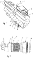
- An electrical connector part 1 according to the Figs. 1 to 8 is designed as a screw-in connector which can be screwed into a passage D of a motor connection box F serving as a functional part.
- the screw-in plug 1 has a plug housing 2 made of plastic, in which a plurality of plug contacts 3 are integrated in a basically known manner.
- the plug housing 2 has a screw section 4 which is formed by an external thread formed integrally on the plug housing 2.
- the electrical plug contacts 3 form a pole arrangement on an end face opposite the screw section 4, which is based on the Figures 4 to 8 is easily recognizable.
- annular radial groove 5 in which a sealing ring 6 made of a suitable elastomer material is embedded, adjoins the screw section 4 of the plug-in housing 2 axially towards the center of the plug-in housing 2.
- the sealing ring 6 forms a radial seal in the area of the screw section 4, as will be described in more detail below.
- the plug-in housing 2 has an integrally formed, radially outwardly projecting annular collar 11, which is designed as a stop collar within the meaning of the invention.
- the screw-in connector 1 is additionally provided with a lock nut 7, which is designed as a hexagonal nut and whose internal thread 8 is complementary to the external thread of the screw section 4 of the plug-in housing 2.
- the lock nut 7 has an annular groove on its end face facing away from the pole arrangement of the electrical plug contacts 3, which is axially open and serves to receive an axial sealing ring 10.
- the internal thread 8 does not extend over the entire axial length of the lock nut 7, but only over a portion of the axial length of the inner circumference of the lock nut 7.
- the internal thread 8 is followed by a cylindrical annular groove 9, the inside diameter of which corresponds to the outside diameter of the plug-in housing 2 is matched in the area of the screw section 4.
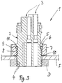
- the lock nut 7 is screwed axially onto the screw section 4 until the lock nut 7 comes to rest on the stop collar 11. Then the plug housing 2 including the lock nut 7 is inserted axially into the passage D of the motor connection box F, the external thread of the screw section 4 engaging in screw engagement with an unspecified, complementary internal thread of the passage D. The screw-in connector 1 is now screwed in until the axial sealing ring 10 of the lock nut 7 comes to rest on the wall section of the motor connection box F (see FIG Fig. 3 ).
- the screw-in plug 1 is screwed in further until the axial sealing ring 10 is compressed and the corresponding end face of the lock nut 7 is pressed against the wall section of the motor connection box F.
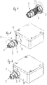
- the alignment of the pole pattern of the electrical plug contacts 3 is checked. The correct positioning of the pole arrangement should be according to the Figures 7 and 8 respectively. If the pole arrangement is in accordance with Fig. 6 is still rotated with respect to this desired alignment, the entire screw-in connector 1 is simply turned back by the desired angle - ie, unscrewed. The plug-in housing 2 is then held in this orientation manually or using a tool and the lock nut 7 is tightened as shown by the arrow in FIG Fig.
- the electrical connector part is designed as a screw-in connector.
- the connector part can also be designed as a screw-in socket.
- the screw-in socket is designed in the same way as the screw-in plug 1 according to FIGS Figs. 1 to 8 .
- the only difference is the design of the plug contacts and the corresponding pin arrangement, which are necessarily designed to be complementary as a counterpart to the plug shape.
Landscapes
- Connector Housings Or Holding Contact Members (AREA)
- Details Of Connecting Devices For Male And Female Coupling (AREA)
Description
- Die Erfindung betrifft ein elektrisches Steckverbindungsteil mit einem Steckgehäuse, in dem elektrische Steckkontakte für eine Steckverbindung mit einem komplementären Steckverbindungsteil integriert sind, und das einen mit einem Außengewinde versehenen Schraubabschnitt zur Sicherung des Steckgehäuses in einem Durchtritt eines ortsfesten Funktionsteils umfasst, sowie mit einem Dichtungsring zum Abdichten des Steckgehäuses relativ zu einem komplementären Gegenstück.
- Ein derartiges elektrisches Steckverbindungsteil ist durch einen elektrischen Einschraubsteckverbinder der Anmelderin allgemein bekannt. Ein derartiger Einschraubsteckverbinder ist zum einen dafür vorgesehen, eine elektrische Verbindung herzustellen. Zum anderen muss er wasser- oder feuchtigkeitsdicht gestaltet sein, um die elektrische Verbindung auch bei feuchter oder nasser Umgebung sicher aufrechterhalten zu können. Zudem ist es bei einem Einschraubsteckverbinder notwendig, eine Befestigung mit einem ausreichend großen Drehmoment vorzunehmen, um zu gewährleisten, dass in normalem Gebrauchszustand kein Lösen des Steckverbinders erfolgen kann. Der Steckverbinder weist ein Steckgehäuse auf, das einen Schraubabschnitt umfasst, der durch ein Außengewinde gebildet ist. Ein Anschlagbund des Steckgehäuses ist mit einer axial wirkenden Dichtung versehen, um in eingeschraubtem Zustand des Steckverbinders im Bereich eines entsprechenden Durchtritts eines Funktionsteils eine ausreichende Abdichtung zu ermöglichen. Nachteilig bei derart verschraubten Steckverbindungsteilen ist es, dass keine definierte Ausrichtung des Polbilds der Steckkontakte in am Funktionsteil festgelegtem Montagezustand des Steckverbinders möglich ist. Denn der Einschraubsteckverbinder muss zur Erzielung der ausreichenden Dichtheit bis hin zur Dichtfläche fest eingeschraubt werden. Zudem muss gewährleistet sein, dass der Einschraubsteckverbinder in abgedichteter Funktionsstellung auch so stark festgedreht ist, dass er sich nicht von selbst lösen kann.
-
US 4 822 293 A undDE 20 2008 001842 U1 offenbaren derartige elektrische Steckverbindungsteile. - Aufgabe der Erfindung ist es, ein elektrisches Steckverbindungsteil der eingangs genannten Art zu schaffen, das eine Ausrichtung des Polbilds der Steckkontakte ermöglicht und dennoch in montiertem Zustand eine dichte Verbindung mit dem Durchtritt des Funktionsteils ermöglicht, die wenigstens die Schutzklasse IP65 der DIN EN 60529 gewährleistet.
- Diese Aufgabe wird dadurch gelöst, dass an den Schraubabschnitt eine Radialnut zur Aufnahme des Dichtungsrings anschließt und dass der Dichtungsring als Radialdichtung gestaltet ist, die in montiertem Zustand den Schraubabschnitt des Steckgehäuses radial zu einem komplementären Gegenstück, insbesondere zu einer Innenwandung des Durchtritts oder zu einer Kontermutter, abdichtet. Dadurch, dass der Dichtungsring als Radialdichtung gestaltet ist, kann eine Abdichtung des Steckgehäuses gegenüber dem Durchtritt radial erfolgen, so dass eine Verdrehung des Steckverbindungsteils in eingeschraubtem Zustand um bestimmte Drehwinkel keinen Einfluss auf die Dichtwirkung des Dichtungsrings hat. Diese Verdrehbarkeit ermöglicht erfindungsgemäß eine exakte Positionierung des Polbilds der Steckkontakte, so dass sie in montiertem Zustand des Steckverbindungsteils symmetrisch zu einer entsprechenden Vertikalen oder Horizontalen des ortsfesten Funktionsteils ausgerichtet werden können. Dies ermöglicht zum einen ein einfaches und intuitives Ausrichten und Einstecken eines komplementären Steckverbindungsteils. Zum anderen vermittelt ein symmetrisch ausgerichtetes Polbild des Steckverbindungsteils einen qualitativ hochwertigen Eindruck. Ortsfeste Funktionsteile im Sinne der Erfindung sind insbesondere Wandungsabschnitte von Trägergehäusen elektrischer oder elektronischer Module, Gehäuseabschnitte von Funktionsmodulen, Wandungsabschnitte und Trägerplattformen von Steuerschränken oder Schaltschrankmodulen oder andere, mit entsprechenden Durchtritten versehene Flächen von Maschinen- oder Anlagenkomponenten.
- In Ausgestaltung der Erfindung ist dem Schraubabschnitt des Steckgehäuses eine Kontermutter zugeordnet, die mit einem axial wirksamen Dichtring an ihrer dem Funktionsteil zugewandten Stirnfläche versehen ist. Die Kontermutter weist ein Innengewinde auf, das komplementär zu dem Außengewinde des Schraubabschnitts des Steckgehäuses gestaltet ist, um ein Auf- und Abschrauben der Kontermutter relativ zum Schraubabschnitt des Steckgehäuses zu ermöglichen.
- In weiterer Ausgestaltung der Erfindung ist koaxial zu dem Schraubabschnitt am Steckgehäuse ein radial nach außen abragender Anschlagbund vorgesehen, der insbesondere einen Schraubweg der Kontermutter begrenzt. Falls das Steckverbindungsteil ohne Kontermutter direkt in ein Innengewinde eines Durchtritts eines entsprechenden Funktionsteils eingeschraubt wird, kann der Anschlagbund dazu dienen, die maximale Einschraubtiefe des Steckverbindungsteils in dem Durchtritt zu begrenzen. Je nach Ausführung kann vorgesehen sein, dass der Anschlagbund oder die Kontermutter zusätzlich zu der Radialdichtung des Schraubabschnitts des Steckgehäuses noch mit einem axialen Dichtring versehen ist, der an einer dem Funktionsteil zugewandten Stirnfläche des Anschlagbunds vorgesehen ist.
- In weiterer Ausgestaltung der Erfindung weist die Kontermutter an ihrem Innenumfang ein zu dem Außengewinde des Steckgehäuses komplementäres Innengewinde sowie einen axial an das Innengewinde anschließenden Ringnutabschnitt auf, der zum dichten radialen Umschließen der Radialdichtung des Schraubabschnitts des Steckgehäuses vorgesehen ist. Zwischen der Kontermutter und der Radialdichtung des Schraubabschnitts des Steckgehäuses ist daher eine dichte Verbindung erzielbar. Falls die Kontermutter selbst ergänzend mit einem axialen Dichtring versehen ist, der an einer dem Funktionsteil zugewandten Dichtfläche der Kontermutter vorgesehen ist, ist zusätzlich eine Dichtung des Steckverbindungsteils einschließlich Kontermutter relativ zu dem den Durchtritt umgebenden Wandungsabschnitt des Funktionsteils erzielbar.
- In weiterer Ausgestaltung der Erfindung ist eine Gewindesteigung des Schraubabschnitts derart auf eine Breite der Radialdichtung abgestimmt, dass eine Drehung über einen Gewindegang zu einem Axialversatz führt, der kleiner oder gleich der Breite der Radialdichtung ist. Dadurch ist gewährleistet, dass eine Verdrehung des Steckverbindungsteils relativ zum Funktionsteil um einen einzelnen Gewindegang, d.h. um 360°, die Dichtwirkung der Radialdichtung nicht beeinträchtigt. Falls das Steckverbindungsteil daher vollständig in dem Durchtritt des Funktionsteils eingeschraubt ist, gewährleistet ein Herausdrehen des Steckverbindungsteils um bis zu etwas mehr als 360°, d.h. eine Drehung um einen vollständigen Gewindegang, dennoch eine gleichblei-bende Dichtwirkung, da die Radialdichtung auch bei einem entsprechend begrenzten Heraus-drehen noch ihre Dichtwirkung zum Innenumfang des Durchtritts hin beibehält. Gleiches gilt für den Fall, dass das Steckverbindungsteil nicht direkt in einen entsprechenden Durchtritt einge-schraubt ist, sondern der Schraubabschnitt des Steckgehäuses noch durch eine Kontermutter umschlossen ist, die eine axiale Abdichtung zum entsprechenden Wandungsabschnitt des Funktionsteils bewirkt. Die maßgebliche Dichtwirkung der Radialdichtung erfolgt dann zwischen der Radialdichtung des Schraubabschnitts und dem Innenmantel der Kontermutter.
- In weiterer Ausgestaltung der Erfindung entspricht eine durch den Ringnutabschnitt der Kontermutter erzeugbare axiale Spaltabdeckung wenigstens der axialen Erstreckung eines Gewindegangs des Innengewindes der Kontermutter. Diese Ausgestaltung gewährleistet eine ausreichende Dichtwirkung zwischen Kontermutter und Schraubabschnitt des Steckgehäuses auch bei einem erneuten Herausdrehen des Schraubabschnitts um einen einzelnen Gewindegang relativ zur Kontermutter, um die gewünschte Positionierung des Polbilds zu erzielen.
- Weitere Vorteile und Merkmale der Erfindung ergeben sich aus den Ansprüchen sowie aus der nachfolgenden Beschreibung eines bevorzugten Ausführungsbeispiels der Erfindung, das anhand der Zeichnungen dargestellt ist.
- Fig. 1
- zeigt in teilgeschnittener isometrischer Darstellung eine Ausführungsform eines erfindungsgemäßen elektrischen Steckverbindungsteils,
- Fig. 2
- das Steckverbindungsteil nach
Fig. 1 in einer Explosionsdarstellung, - Fig. 3
- in einer Schnittdarstellung das Steckverbindungsteil nach den
Fig. 1 und 2 in montiertem Funktionszustand an einer Wandung eines Funktionsteils und - Fig. 4 bis 8
- verschiedene Schritte der Montage eines elektrischen Steckverbindungsteils an einem Funktionsteil in Form eines Motoranschlusskastens.
- Ein elektrisches Steckverbindungsteil 1 nach den
Fig. 1 bis 8 ist als Einschraubstecker gestaltet, der in einen Durchtritt D eines als Funktionsteil dienenden Motoranschlusskastens F einschraubbar ist. Der Einschraubstecker 1 weist ein aus Kunststoff bestehendes Steckgehäuse 2 auf, in dem mehrere Steckkontakte 3 in grundsätzlich bekannter Weise integriert sind. Das Steckgehäuse 2 weist einen Schraubabschnitt 4 auf, der durch ein einstückig am Steckgehäuse 2 angeformtes Außengewinde gebildet ist. Die elektrischen Steckkontakte 3 bilden auf einer dem Schraubabschnitt 4 gegenüberliegenden Stirnseite ein Polbild, das anhand derFig. 4 bis 8 gut erkennbar ist. - An den Schraubabschnitt 4 des Steckgehäuses 2 schließt axial zur Mitte des Steckgehäuses 2 hin eine ringförmige Radialnut 5 an, in der ein Dichtungsring 6 aus einem geeigneten Elastomermaterial eingebettet ist. Der Dichtungsring 6 bildet eine Radialdichtung im Bereich des Schraubabschnitts 4, wie nachfolgend näher beschrieben wird. In geringem axialem Abstand zu der Radialnut 5 weist das Steckgehäuse 2 einen einstückig angeformten, radial nach außen ragenden Ringbund 11 auf, der als Anschlagbund im Sinne der Erfindung gestaltet ist.
- Beim dargestellten Ausführungsbeispiel ist der Einschraubstecker 1 zusätzlich mit einer Kontermutter 7 versehen, die als Sechskantmutter gestaltet ist und mit ihrem Innengewinde 8 komplementär auf das Außengewinde des Schraubabschnitts 4 des Steckgehäuses 2 abgestimmt ist. Die Kontermutter 7 weist auf ihrer vom Polbild der elektrischen Steckkontakte 3 abgewandten Stirnseite eine Ringnut auf, die axial offen ist und zur Aufnahme eines axialen Dichtungsrings 10 dient. Das Innengewinde 8 erstreckt sich nicht über die gesamte axiale Länge der Kontermutter 7, sondern lediglich über einen Teilbereich der axialen Länge des Innenumfangs der Kontermutter 7. An das Innengewinde 8 schließt eine zylindrische Ringnut 9 an, die in ihrem Innendurchmesser auf den Außendurchmesser des Steckgehäuses 2 im Bereich des Schraubabschnitts 4 abgestimmt ist. Beim axialen Aufschrauben der Kontermutter 7 auf den Schraubabschnitt 4 des Steckgehäuses 2 gerät die dem Ringnutabschnitt 9 benachbarte Stirnseite der Kontermutter 7 in der aufgeschraubten Endposition an dem Anschlagbund 11 des Steckgehäuses 2 axial zur Anlage, wie
Fig. 3 zu entnehmen ist. Die Axialerstreckung des Ringnutabschnitts 9 ist 1,5- bis 2-mal so groß wie die Axialerstreckung der Radialnut 5, in der die Radialdichtung 6 des Schraubabschnitts 4 aufgenommen ist. In vollständig aufgeschraubtem Zustand der Kontermutter 7 gemäßFig. 3 liegt die Stirnseite der Kontermutter 7 an dem Anschlagbund 11 axial an. Der Ringnutabschnitt 9 überdeckt die Radialnut 5 vollständig und dichtet mit der Radialdichtung 6 ab. Das Innengewinde 8 greift im Bereich der Gewindegänge noch in das Außengewinde des Schraubabschnitts 4 ein. - Zum Montieren des Einschraubsteckers 1 wird zunächst gemäß
Fig. 4 die Kontermutter 7 auf den Schraubabschnitt 4 axial aufgeschraubt, bis die Kontermutter 7 am Anschlagbund 11 zur Anlage kommt. Anschließend wird das Steckgehäuse 2 einschließlich Kontermutter 7 in den Durchtritt D des Motoranschlusskastens F axial eingeführt, wobei das Außengewinde des Schraubabschnitts 4 in Schraubeingriff mit einem nicht näher bezeichneten, komplementären Innengewinde des Durchtritts D in Eingriff gelangt. Nun wird der Einschraubstecker 1 so weit eingeschraubt, bis der axiale Dichtungsring 10 der Kontermutter 7 an dem Wandungsabschnitt des Motoranschlusskastens F zur Anlage kommt (sieheFig. 3 ). Der Einschraubstecker 1 wird weiter eingeschraubt, bis der axiale Dichtungsring 10 komprimiert ist und die entsprechende Stirnseite der Kontermutter 7 gegen den Wandungsabschnitt des Motoranschlusskastens F gepresst ist. Nach dem vollständigen Einschrauben des Einschraubsteckers 1 gemäßFig. 6 wird die Ausrichtung des Polbilds der elektrischen Steckkontakte 3 geprüft. Die korrekte Positionierung des Polbilds sollte gemäß denFig. 7 und 8 erfolgen. Falls das Polbild gemäßFig. 6 noch gegenüber dieser gewünschten Ausrichtung verdreht ist, wird in einfacher Weise der gesamte Einschraubstecker 1 wieder um den gewünschten Winkel zurück - d.h. aufgedreht. Anschließend wird das Steckgehäuse 2 in dieser Ausrichtung manuell oder durch ein Werkzeug festgehalten und die Kontermutter 7 wird gemäß der Pfeildarstellung inFig. 8 soweit wieder zum Motoranschlusskasten F hin festgedreht, bis die Stirnseite der Kontermutter 7 mit dem axialen Dichtungsring 10 dicht an dem Wandungsabschnitt des Motoranschlusskastens F anliegt. Nun ist der Einschraubstecker 1 abgedichtet fixiert am Motoranschlusskasten F. Die gesamte Ausführung der Dichtwirkungen und der Montage des Einschraubsteckers 1 am Motoranschlusskasten F entsprechen wenigstens der Schutzklasse IP65. - Bei der Ausführungsform nach den
Fig. 1 bis 8 ist das elektrische Steckverbindungsteil als Einschraubstecker gestaltet. In gleicher Weise kann das Steckverbindungsteil aber auch als Einschraubbuchse gestaltet sein. Die Einschraubbuchse ist in gleicher Weise gestaltet wie der Einschraubstecker 1 gemäß denFig. 1 bis 8 . Einziger Unterschied ist die Gestaltung der Steckkontakte und des entsprechenden Polbilds, die zwangsläufig komplementär als Gegenstück zu der Steckerform gestaltet sind.
Claims (8)
- Elektrisches Steckverbindungsteil (1) mit einem Steckgehäuse (2), in dem elektrische Stecckontakte (3) für eine Steckverbindung mit einem komplementären Steckverbindungsteil integriert sind, und das einen mit einem Außengewinde versehenen Schraubabschnitt: (4) zur Sicherung des Steckgehäuses in einem Durchtritt (D) eines ortsfesten Funktionsteils (F) umfasst, sowie mit einem Dichtungsring (6) zum Abdichten des Steckgehäuses relativ ; zu einem komplementären Gegenstück, dadurch gekennzeichnet, dass an den Schraubabschnitt (4) eine Radialnut (5) zur Aufnahme des Dichtungsrings (6) anschließt, und dass der Dichtungsring als Radialdichtung (6) gestaltet ist, die in montiertem Zustand den Schraubabschnitt (4) des Steckgehäuses (2) radial zu dem komplementären Gegenstück abdichtet.
- Elektrisches Steckverbindungsteil nach Anspruch 1, dadurch gekennzeichnet, dass als komplementäres Gegenstück eine Innenwandung des Durchtritts (D) oder eine Kontermutter (7) vorgesehen ist.
- Elektrisches Steckverbindungsteil nach Anspruch 1 oder 2, dadurch gekennzeichnet, dass dem Schraubabschnitt (4) des Steckgehäuses (2) eine Kontermutter (7) zugeordnet ist, die mit einem axial wirksamen Dichtring (10) an ihrer dem Funktionsteil (F) zugewandten Stirnfläche versehen ist.
- Elektrisches Steckverbindungsteil nach Anspruch 1, 2 oder 3, dadurch gekennzeichnet, dass koaxial zu dem Schraubabschnitt (4) am Steckgehäuse (2) ein radial nach außen ab-ragender Anschlagbund (11) vorgesehen ist.
- Elektrisches Steckverbindungsteil nach Anspruch 4, dadurch gekennzeichnet, dass der Anschlagbund (11) einen Schraubweg der Kontermutter (7) begrenzt.
- Elektrisches Steckverbindungsteil nach Anspruch3, dadurch gekennzeichnet, dass die Kontermutter (7) an ihrem Innenumfang ein zu dem Außengewinde des Steckgehäuses (2) komplementäres Innengewinde (8) sowie einen axial an das Innengewinde (8) anschließenden Ringnutabschnitt (9) aufweist, der zum dichten radialen Umschließen der Radialdichtung (6) des Schraubabschnitts (4) des Steckgehäuses (2) vorgesehen ist.
- Elektrisches Steckverbindungsteil nach einem der vorhergehenden Ansprüche, dadurch gekennzeichnet, dass eine Gewindesteigung des Schraubabschnitts (4) derart auf eine Breite der Radialdichtung (6) abgestimmt ist, dass eine Drehung über einen Gewindegang zu einem Axialversatz führt, der kleiner oder gleich der Breite der Radialdichtung ist.
- Elektrisches Steckverbindungsteil nach einem der vorhergehenden Ansprüche, dadurch gekennzeichnet, dass eine durch den Ringnutabschnitt (9) der Kontermutter (7) erzeugbare axiale Spaltabdeckung wenigstens der axialen Erstreckung eines Gewindegangs des Innengewindes (8) der Kontermutter (7) entspricht.
Applications Claiming Priority (2)
| Application Number | Priority Date | Filing Date | Title |
|---|---|---|---|
| DE102013223942.4A DE102013223942A1 (de) | 2013-11-22 | 2013-11-22 | Elektrisches Steckverbindungsteil |
| PCT/EP2014/074779 WO2015074996A1 (de) | 2013-11-22 | 2014-11-17 | Wasserdichtes steckverbindungsteil |
Publications (2)
| Publication Number | Publication Date |
|---|---|
| EP3072183A1 EP3072183A1 (de) | 2016-09-28 |
| EP3072183B1 true EP3072183B1 (de) | 2020-08-19 |
Family
ID=51903919
Family Applications (1)
| Application Number | Title | Priority Date | Filing Date |
|---|---|---|---|
| EP14799449.5A Active EP3072183B1 (de) | 2013-11-22 | 2014-11-17 | Wasserdichtes steckverbindungsteil |
Country Status (4)
| Country | Link |
|---|---|
| EP (1) | EP3072183B1 (de) |
| DE (1) | DE102013223942A1 (de) |
| ES (1) | ES2829502T3 (de) |
| WO (1) | WO2015074996A1 (de) |
Citations (1)
| Publication number | Priority date | Publication date | Assignee | Title |
|---|---|---|---|---|
| US4822293A (en) * | 1987-11-20 | 1989-04-18 | General Dynamics, Pomona Division | Bell housing sealing assembly for mounted connector |
Family Cites Families (5)
| Publication number | Priority date | Publication date | Assignee | Title |
|---|---|---|---|---|
| US3998515A (en) * | 1975-09-25 | 1976-12-21 | International Telephone And Telegraph Corporation | Hermetic electrical penetrator |
| US20040043667A1 (en) * | 2002-08-27 | 2004-03-04 | Hsien-Te Chen | Connector structure for rope light |
| FR2911727B1 (fr) * | 2007-01-22 | 2011-03-25 | Souriau | Connecteur disposant d'une barriere d'etancheite et procede de fabrication d'un tel connecteur. |
| DE202008001842U1 (de) * | 2008-02-09 | 2008-04-10 | Jacob Gmbh Elektrotechnische Fabrik | Steckvorrichtung |
| US20100190375A1 (en) * | 2009-01-27 | 2010-07-29 | Rohde Daniel F | Connector receptacle with molded front nut gasket |
-
2013
- 2013-11-22 DE DE102013223942.4A patent/DE102013223942A1/de not_active Ceased
-
2014
- 2014-11-17 ES ES14799449T patent/ES2829502T3/es active Active
- 2014-11-17 WO PCT/EP2014/074779 patent/WO2015074996A1/de not_active Ceased
- 2014-11-17 EP EP14799449.5A patent/EP3072183B1/de active Active
Patent Citations (1)
| Publication number | Priority date | Publication date | Assignee | Title |
|---|---|---|---|---|
| US4822293A (en) * | 1987-11-20 | 1989-04-18 | General Dynamics, Pomona Division | Bell housing sealing assembly for mounted connector |
Also Published As
| Publication number | Publication date |
|---|---|
| ES2829502T3 (es) | 2021-06-01 |
| DE102013223942A1 (de) | 2015-05-28 |
| EP3072183A1 (de) | 2016-09-28 |
| WO2015074996A1 (de) | 2015-05-28 |
Similar Documents
| Publication | Publication Date | Title |
|---|---|---|
| EP2264848B1 (de) | Kabelverschraubung | |
| EP3042423B1 (de) | Steckverbindergehäuse | |
| EP2695263B1 (de) | Kabelabschlusseinrichtung | |
| EP2240987B1 (de) | Steckvorrichtung | |
| EP3132506B1 (de) | Kabelabgang | |
| DE202005009396U1 (de) | Elektrische Steckverbindung | |
| WO2012045431A1 (de) | Elektrischer leitungsverbinder | |
| DE10311473B3 (de) | Kabelverschraubung | |
| EP3292603B1 (de) | Kabel-/leitungseinführung | |
| DE102010031345A1 (de) | Manipulationssichere Kabeldurchführung | |
| DE102008057473B4 (de) | Kabeldurchführung | |
| DE102011050455A1 (de) | Sensoranordnung mit zwei gegeneinander drehbaren Gehäuseteilen | |
| WO2012045430A2 (de) | Kabelabschlusseinrichtung | |
| DE102014102745B4 (de) | Vorrichtung zur bereitstellung einer abgedichteten kabeldurchführung und wechselrichter | |
| DE102009033948A1 (de) | Kabel- oder Schlauchverschraubung | |
| DE19908657C1 (de) | Vorrichtung zum Abdecken und Abdichten eines Kabeldurchführungsdurchbruches in einer Wand eines Schaltschrankes | |
| WO2015074996A1 (de) | Wasserdichtes steckverbindungsteil | |
| DE102014012335A1 (de) | Elektrisches Gerät | |
| EP2076940A1 (de) | Elektrischer steckverbinder | |
| DE102012005545A1 (de) | Kabelabschlusseinrichtung | |
| DE102005019245B3 (de) | Optimierte Anschließbarkeit durch axiales Rasten von elektrischen Steckvorrichtungen | |
| AT518011B1 (de) | Anordnung umfassend ein elektrisches Gerät und ein Verbindungskabel | |
| DE102013101123B4 (de) | Steckverbindergehäuse | |
| EP2727189B1 (de) | Vorrichtung zum bedarfsweisen staub- und/oder feuchtigkeitsschutz für stromführende geräteanschluss- oder verbindungsmittel | |
| EP2633594A1 (de) | Wandeinsatz |
Legal Events
| Date | Code | Title | Description |
|---|---|---|---|
| PUAI | Public reference made under article 153(3) epc to a published international application that has entered the european phase |
Free format text: ORIGINAL CODE: 0009012 |
|
| 17P | Request for examination filed |
Effective date: 20160512 |
|
| AK | Designated contracting states |
Kind code of ref document: A1 Designated state(s): AL AT BE BG CH CY CZ DE DK EE ES FI FR GB GR HR HU IE IS IT LI LT LU LV MC MK MT NL NO PL PT RO RS SE SI SK SM TR |
|
| AX | Request for extension of the european patent |
Extension state: BA ME |
|
| DAX | Request for extension of the european patent (deleted) | ||
| STAA | Information on the status of an ep patent application or granted ep patent |
Free format text: STATUS: EXAMINATION IS IN PROGRESS |
|
| 17Q | First examination report despatched |
Effective date: 20180416 |
|
| REG | Reference to a national code |
Ref country code: DE Ref legal event code: R079 Ref document number: 502014014652 Country of ref document: DE Free format text: PREVIOUS MAIN CLASS: H01R0013520000 Ipc: H02G0003060000 |
|
| GRAP | Despatch of communication of intention to grant a patent |
Free format text: ORIGINAL CODE: EPIDOSNIGR1 |
|
| STAA | Information on the status of an ep patent application or granted ep patent |
Free format text: STATUS: GRANT OF PATENT IS INTENDED |
|
| RIC1 | Information provided on ipc code assigned before grant |
Ipc: H02G 3/06 20060101AFI20200225BHEP Ipc: H01R 13/74 20060101ALI20200225BHEP Ipc: H02G 3/22 20060101ALI20200225BHEP Ipc: H01R 13/52 20060101ALI20200225BHEP |
|
| INTG | Intention to grant announced |
Effective date: 20200327 |
|
| GRAS | Grant fee paid |
Free format text: ORIGINAL CODE: EPIDOSNIGR3 |
|
| GRAA | (expected) grant |
Free format text: ORIGINAL CODE: 0009210 |
|
| STAA | Information on the status of an ep patent application or granted ep patent |
Free format text: STATUS: THE PATENT HAS BEEN GRANTED |
|
| AK | Designated contracting states |
Kind code of ref document: B1 Designated state(s): AL AT BE BG CH CY CZ DE DK EE ES FI FR GB GR HR HU IE IS IT LI LT LU LV MC MK MT NL NO PL PT RO RS SE SI SK SM TR |
|
| REG | Reference to a national code |
Ref country code: CH Ref legal event code: EP |
|
| REG | Reference to a national code |
Ref country code: DE Ref legal event code: R096 Ref document number: 502014014652 Country of ref document: DE |
|
| REG | Reference to a national code |
Ref country code: AT Ref legal event code: REF Ref document number: 1305044 Country of ref document: AT Kind code of ref document: T Effective date: 20200915 |
|
| REG | Reference to a national code |
Ref country code: IE Ref legal event code: FG4D Free format text: LANGUAGE OF EP DOCUMENT: GERMAN |
|
| REG | Reference to a national code |
Ref country code: CH Ref legal event code: NV Representative=s name: DR. LUSUARDI AG, CH |
|
| REG | Reference to a national code |
Ref country code: FI Ref legal event code: FGE |
|
| REG | Reference to a national code |
Ref country code: NL Ref legal event code: FP |
|
| REG | Reference to a national code |
Ref country code: SE Ref legal event code: TRGR |
|
| REG | Reference to a national code |
Ref country code: LT Ref legal event code: MG4D |
|
| PG25 | Lapsed in a contracting state [announced via postgrant information from national office to epo] |
Ref country code: LT Free format text: LAPSE BECAUSE OF FAILURE TO SUBMIT A TRANSLATION OF THE DESCRIPTION OR TO PAY THE FEE WITHIN THE PRESCRIBED TIME-LIMIT Effective date: 20200819 Ref country code: HR Free format text: LAPSE BECAUSE OF FAILURE TO SUBMIT A TRANSLATION OF THE DESCRIPTION OR TO PAY THE FEE WITHIN THE PRESCRIBED TIME-LIMIT Effective date: 20200819 Ref country code: BG Free format text: LAPSE BECAUSE OF FAILURE TO SUBMIT A TRANSLATION OF THE DESCRIPTION OR TO PAY THE FEE WITHIN THE PRESCRIBED TIME-LIMIT Effective date: 20201119 Ref country code: NO Free format text: LAPSE BECAUSE OF FAILURE TO SUBMIT A TRANSLATION OF THE DESCRIPTION OR TO PAY THE FEE WITHIN THE PRESCRIBED TIME-LIMIT Effective date: 20201119 Ref country code: PT Free format text: LAPSE BECAUSE OF FAILURE TO SUBMIT A TRANSLATION OF THE DESCRIPTION OR TO PAY THE FEE WITHIN THE PRESCRIBED TIME-LIMIT Effective date: 20201221 Ref country code: GR Free format text: LAPSE BECAUSE OF FAILURE TO SUBMIT A TRANSLATION OF THE DESCRIPTION OR TO PAY THE FEE WITHIN THE PRESCRIBED TIME-LIMIT Effective date: 20201120 |
|
| PG25 | Lapsed in a contracting state [announced via postgrant information from national office to epo] |
Ref country code: LV Free format text: LAPSE BECAUSE OF FAILURE TO SUBMIT A TRANSLATION OF THE DESCRIPTION OR TO PAY THE FEE WITHIN THE PRESCRIBED TIME-LIMIT Effective date: 20200819 Ref country code: RS Free format text: LAPSE BECAUSE OF FAILURE TO SUBMIT A TRANSLATION OF THE DESCRIPTION OR TO PAY THE FEE WITHIN THE PRESCRIBED TIME-LIMIT Effective date: 20200819 Ref country code: IS Free format text: LAPSE BECAUSE OF FAILURE TO SUBMIT A TRANSLATION OF THE DESCRIPTION OR TO PAY THE FEE WITHIN THE PRESCRIBED TIME-LIMIT Effective date: 20201219 |
|
| PG25 | Lapsed in a contracting state [announced via postgrant information from national office to epo] |
Ref country code: DK Free format text: LAPSE BECAUSE OF FAILURE TO SUBMIT A TRANSLATION OF THE DESCRIPTION OR TO PAY THE FEE WITHIN THE PRESCRIBED TIME-LIMIT Effective date: 20200819 Ref country code: EE Free format text: LAPSE BECAUSE OF FAILURE TO SUBMIT A TRANSLATION OF THE DESCRIPTION OR TO PAY THE FEE WITHIN THE PRESCRIBED TIME-LIMIT Effective date: 20200819 Ref country code: SM Free format text: LAPSE BECAUSE OF FAILURE TO SUBMIT A TRANSLATION OF THE DESCRIPTION OR TO PAY THE FEE WITHIN THE PRESCRIBED TIME-LIMIT Effective date: 20200819 Ref country code: RO Free format text: LAPSE BECAUSE OF FAILURE TO SUBMIT A TRANSLATION OF THE DESCRIPTION OR TO PAY THE FEE WITHIN THE PRESCRIBED TIME-LIMIT Effective date: 20200819 |
|
| REG | Reference to a national code |
Ref country code: DE Ref legal event code: R097 Ref document number: 502014014652 Country of ref document: DE |
|
| PG25 | Lapsed in a contracting state [announced via postgrant information from national office to epo] |
Ref country code: AL Free format text: LAPSE BECAUSE OF FAILURE TO SUBMIT A TRANSLATION OF THE DESCRIPTION OR TO PAY THE FEE WITHIN THE PRESCRIBED TIME-LIMIT Effective date: 20200819 |
|
| REG | Reference to a national code |
Ref country code: ES Ref legal event code: FG2A Ref document number: 2829502 Country of ref document: ES Kind code of ref document: T3 Effective date: 20210601 |
|
| PLBE | No opposition filed within time limit |
Free format text: ORIGINAL CODE: 0009261 |
|
| STAA | Information on the status of an ep patent application or granted ep patent |
Free format text: STATUS: NO OPPOSITION FILED WITHIN TIME LIMIT |
|
| PG25 | Lapsed in a contracting state [announced via postgrant information from national office to epo] |
Ref country code: MC Free format text: LAPSE BECAUSE OF FAILURE TO SUBMIT A TRANSLATION OF THE DESCRIPTION OR TO PAY THE FEE WITHIN THE PRESCRIBED TIME-LIMIT Effective date: 20200819 Ref country code: SK Free format text: LAPSE BECAUSE OF FAILURE TO SUBMIT A TRANSLATION OF THE DESCRIPTION OR TO PAY THE FEE WITHIN THE PRESCRIBED TIME-LIMIT Effective date: 20200819 |
|
| 26N | No opposition filed |
Effective date: 20210520 |
|
| PG25 | Lapsed in a contracting state [announced via postgrant information from national office to epo] |
Ref country code: LU Free format text: LAPSE BECAUSE OF NON-PAYMENT OF DUE FEES Effective date: 20201117 |
|
| PG25 | Lapsed in a contracting state [announced via postgrant information from national office to epo] |
Ref country code: SI Free format text: LAPSE BECAUSE OF FAILURE TO SUBMIT A TRANSLATION OF THE DESCRIPTION OR TO PAY THE FEE WITHIN THE PRESCRIBED TIME-LIMIT Effective date: 20200819 |
|
| PG25 | Lapsed in a contracting state [announced via postgrant information from national office to epo] |
Ref country code: IE Free format text: LAPSE BECAUSE OF NON-PAYMENT OF DUE FEES Effective date: 20201117 |
|
| PG25 | Lapsed in a contracting state [announced via postgrant information from national office to epo] |
Ref country code: MT Free format text: LAPSE BECAUSE OF FAILURE TO SUBMIT A TRANSLATION OF THE DESCRIPTION OR TO PAY THE FEE WITHIN THE PRESCRIBED TIME-LIMIT Effective date: 20200819 Ref country code: CY Free format text: LAPSE BECAUSE OF FAILURE TO SUBMIT A TRANSLATION OF THE DESCRIPTION OR TO PAY THE FEE WITHIN THE PRESCRIBED TIME-LIMIT Effective date: 20200819 |
|
| PG25 | Lapsed in a contracting state [announced via postgrant information from national office to epo] |
Ref country code: MK Free format text: LAPSE BECAUSE OF FAILURE TO SUBMIT A TRANSLATION OF THE DESCRIPTION OR TO PAY THE FEE WITHIN THE PRESCRIBED TIME-LIMIT Effective date: 20200819 |
|
| PGFP | Annual fee paid to national office [announced via postgrant information from national office to epo] |
Ref country code: NL Payment date: 20231122 Year of fee payment: 10 |
|
| PGFP | Annual fee paid to national office [announced via postgrant information from national office to epo] |
Ref country code: GB Payment date: 20231123 Year of fee payment: 10 |
|
| PGFP | Annual fee paid to national office [announced via postgrant information from national office to epo] |
Ref country code: ES Payment date: 20231215 Year of fee payment: 10 |
|
| PGFP | Annual fee paid to national office [announced via postgrant information from national office to epo] |
Ref country code: TR Payment date: 20231109 Year of fee payment: 10 Ref country code: SE Payment date: 20231123 Year of fee payment: 10 Ref country code: CZ Payment date: 20231103 Year of fee payment: 10 Ref country code: FI Payment date: 20231120 Year of fee payment: 10 |
|
| PGFP | Annual fee paid to national office [announced via postgrant information from national office to epo] |
Ref country code: BE Payment date: 20231121 Year of fee payment: 10 |
|
| REG | Reference to a national code |
Ref country code: SE Ref legal event code: EUG |
|
| PG25 | Lapsed in a contracting state [announced via postgrant information from national office to epo] |
Ref country code: FI Free format text: LAPSE BECAUSE OF NON-PAYMENT OF DUE FEES Effective date: 20241117 |
|
| REG | Reference to a national code |
Ref country code: NL Ref legal event code: MM Effective date: 20241201 |
|
| GBPC | Gb: european patent ceased through non-payment of renewal fee |
Effective date: 20241117 |
|
| PG25 | Lapsed in a contracting state [announced via postgrant information from national office to epo] |
Ref country code: CZ Free format text: LAPSE BECAUSE OF NON-PAYMENT OF DUE FEES Effective date: 20241117 |
|
| PG25 | Lapsed in a contracting state [announced via postgrant information from national office to epo] |
Ref country code: NL Free format text: LAPSE BECAUSE OF NON-PAYMENT OF DUE FEES Effective date: 20241201 |
|
| REG | Reference to a national code |
Ref country code: BE Ref legal event code: MM Effective date: 20241130 |
|
| PG25 | Lapsed in a contracting state [announced via postgrant information from national office to epo] |
Ref country code: SE Free format text: LAPSE BECAUSE OF NON-PAYMENT OF DUE FEES Effective date: 20241118 |
|
| PG25 | Lapsed in a contracting state [announced via postgrant information from national office to epo] |
Ref country code: BE Free format text: LAPSE BECAUSE OF NON-PAYMENT OF DUE FEES Effective date: 20241130 Ref country code: GB Free format text: LAPSE BECAUSE OF NON-PAYMENT OF DUE FEES Effective date: 20241117 |
|
| REG | Reference to a national code |
Ref country code: CH Ref legal event code: U11 Free format text: ST27 STATUS EVENT CODE: U-0-0-U10-U11 (AS PROVIDED BY THE NATIONAL OFFICE) Effective date: 20251201 |
|
| REG | Reference to a national code |
Ref country code: ES Ref legal event code: FD2A Effective date: 20260105 |
|
| PGFP | Annual fee paid to national office [announced via postgrant information from national office to epo] |
Ref country code: DE Payment date: 20251126 Year of fee payment: 12 |
|
| PGFP | Annual fee paid to national office [announced via postgrant information from national office to epo] |
Ref country code: AT Payment date: 20251117 Year of fee payment: 12 |
|
| PGFP | Annual fee paid to national office [announced via postgrant information from national office to epo] |
Ref country code: IT Payment date: 20251128 Year of fee payment: 12 |
|
| PGFP | Annual fee paid to national office [announced via postgrant information from national office to epo] |
Ref country code: FR Payment date: 20251125 Year of fee payment: 12 |
|
| PGFP | Annual fee paid to national office [announced via postgrant information from national office to epo] |
Ref country code: CH Payment date: 20251201 Year of fee payment: 12 |
|
| PGFP | Annual fee paid to national office [announced via postgrant information from national office to epo] |
Ref country code: PL Payment date: 20251024 Year of fee payment: 12 |
|
| PG25 | Lapsed in a contracting state [announced via postgrant information from national office to epo] |
Ref country code: ES Free format text: LAPSE BECAUSE OF NON-PAYMENT OF DUE FEES Effective date: 20241118 |
|
| PG25 | Lapsed in a contracting state [announced via postgrant information from national office to epo] |
Ref country code: TR Free format text: LAPSE BECAUSE OF NON-PAYMENT OF DUE FEES Effective date: 20241117 |