EP3072579A1 - Dispositif de cavitation - Google Patents
Dispositif de cavitation Download PDFInfo
- Publication number
- EP3072579A1 EP3072579A1 EP15000878.7A EP15000878A EP3072579A1 EP 3072579 A1 EP3072579 A1 EP 3072579A1 EP 15000878 A EP15000878 A EP 15000878A EP 3072579 A1 EP3072579 A1 EP 3072579A1
- Authority
- EP
- European Patent Office
- Prior art keywords
- rotor
- teeth
- stator
- rows
- cavitation
- Prior art date
- Legal status (The legal status is an assumption and is not a legal conclusion. Google has not performed a legal analysis and makes no representation as to the accuracy of the status listed.)
- Granted
Links
- 239000007788 liquid Substances 0.000 claims description 57
- 239000012530 fluid Substances 0.000 claims description 5
- 230000033001 locomotion Effects 0.000 description 14
- 230000015572 biosynthetic process Effects 0.000 description 11
- 230000010349 pulsation Effects 0.000 description 11
- 230000007423 decrease Effects 0.000 description 6
- 239000007789 gas Substances 0.000 description 6
- 238000000034 method Methods 0.000 description 6
- 230000008569 process Effects 0.000 description 5
- 239000002245 particle Substances 0.000 description 4
- 230000035939 shock Effects 0.000 description 4
- 238000010276 construction Methods 0.000 description 3
- 238000002156 mixing Methods 0.000 description 3
- 230000010355 oscillation Effects 0.000 description 3
- 230000002093 peripheral effect Effects 0.000 description 3
- 239000007787 solid Substances 0.000 description 3
- 238000009835 boiling Methods 0.000 description 2
- 230000008859 change Effects 0.000 description 2
- 230000001186 cumulative effect Effects 0.000 description 2
- 230000000694 effects Effects 0.000 description 2
- 210000000056 organ Anatomy 0.000 description 2
- 238000009987 spinning Methods 0.000 description 2
- 230000003068 static effect Effects 0.000 description 2
- XLYOFNOQVPJJNP-UHFFFAOYSA-N water Substances O XLYOFNOQVPJJNP-UHFFFAOYSA-N 0.000 description 2
- 230000008901 benefit Effects 0.000 description 1
- 238000003889 chemical engineering Methods 0.000 description 1
- 150000001875 compounds Chemical class 0.000 description 1
- 238000009833 condensation Methods 0.000 description 1
- 230000005494 condensation Effects 0.000 description 1
- 230000001419 dependent effect Effects 0.000 description 1
- 230000001066 destructive effect Effects 0.000 description 1
- 239000003344 environmental pollutant Substances 0.000 description 1
- 230000003628 erosive effect Effects 0.000 description 1
- 238000000227 grinding Methods 0.000 description 1
- 230000006872 improvement Effects 0.000 description 1
- 238000005461 lubrication Methods 0.000 description 1
- 230000007246 mechanism Effects 0.000 description 1
- 238000005457 optimization Methods 0.000 description 1
- 231100000719 pollutant Toxicity 0.000 description 1
- 230000001681 protective effect Effects 0.000 description 1
- 238000000746 purification Methods 0.000 description 1
- 229920006395 saturated elastomer Polymers 0.000 description 1
- 238000007789 sealing Methods 0.000 description 1
- 238000004904 shortening Methods 0.000 description 1
- 230000006641 stabilisation Effects 0.000 description 1
- 238000011105 stabilization Methods 0.000 description 1
- 230000000087 stabilizing effect Effects 0.000 description 1
- 230000009466 transformation Effects 0.000 description 1
Images


Classifications
-
- B—PERFORMING OPERATIONS; TRANSPORTING
- B01—PHYSICAL OR CHEMICAL PROCESSES OR APPARATUS IN GENERAL
- B01F—MIXING, e.g. DISSOLVING, EMULSIFYING OR DISPERSING
- B01F27/00—Mixers with rotary stirring devices in fixed receptacles; Kneaders
- B01F27/27—Mixers with stator-rotor systems, e.g. with intermeshing teeth or cylinders or having orifices
- B01F27/272—Mixers with stator-rotor systems, e.g. with intermeshing teeth or cylinders or having orifices with means for moving the materials to be mixed axially between the surfaces of the rotor and the stator, e.g. the stator rotor system formed by conical or cylindrical surfaces
- B01F27/2721—Mixers with stator-rotor systems, e.g. with intermeshing teeth or cylinders or having orifices with means for moving the materials to be mixed axially between the surfaces of the rotor and the stator, e.g. the stator rotor system formed by conical or cylindrical surfaces provided with intermeshing elements
-
- B—PERFORMING OPERATIONS; TRANSPORTING
- B01—PHYSICAL OR CHEMICAL PROCESSES OR APPARATUS IN GENERAL
- B01F—MIXING, e.g. DISSOLVING, EMULSIFYING OR DISPERSING
- B01F27/00—Mixers with rotary stirring devices in fixed receptacles; Kneaders
- B01F27/27—Mixers with stator-rotor systems, e.g. with intermeshing teeth or cylinders or having orifices
- B01F27/272—Mixers with stator-rotor systems, e.g. with intermeshing teeth or cylinders or having orifices with means for moving the materials to be mixed axially between the surfaces of the rotor and the stator, e.g. the stator rotor system formed by conical or cylindrical surfaces
- B01F27/2724—Mixers with stator-rotor systems, e.g. with intermeshing teeth or cylinders or having orifices with means for moving the materials to be mixed axially between the surfaces of the rotor and the stator, e.g. the stator rotor system formed by conical or cylindrical surfaces the relative position of the stator and the rotor, gap in between or gap with the walls being adjustable
-
- B—PERFORMING OPERATIONS; TRANSPORTING
- B01—PHYSICAL OR CHEMICAL PROCESSES OR APPARATUS IN GENERAL
- B01F—MIXING, e.g. DISSOLVING, EMULSIFYING OR DISPERSING
- B01F27/00—Mixers with rotary stirring devices in fixed receptacles; Kneaders
- B01F27/40—Mixers with rotor-rotor system, e.g. with intermeshing teeth
- B01F27/41—Mixers with rotor-rotor system, e.g. with intermeshing teeth with the mutually rotating surfaces facing each other
- B01F27/411—Mixers with rotor-rotor system, e.g. with intermeshing teeth with the mutually rotating surfaces facing each other provided with intermeshing elements
Definitions
- the invention refers to a cavitation device comprising a rotor arranged to rotate about a rotation axis and a stator, the rotor and the stator each comprising teeth arranged along a circle, the teeth of the rotor and the teeth of the stator having cavitation surfaces facing each other and defining a gap between them in order to induce cavitation in a liquid flowing therethrough.
- Cavitation devices are used to induce cavitation in a liquid. Cavitation is the formation of vapor cavities in a liquid that are the consequence of cavitational forces acting upon the liquid. Cavitation usually occurs when a liquid is subjected to rapid changes of pressure that cause the formation of cavities where the pressure is relatively low. When subjected to higher pressure, the voids implode and can generate an intense shockwave. The maximum pressure amplitude caused by an implosion can reach several thousand N/cm 2 . Since the shock waves formed by collapse of the voids are strong enough to cause significant damage to moving parts, cavitation is usually an undesirable phenomenon. However, there are numerous applications, in which cavitation is caused to happen on purpose in order to treat liquids.
- cavitation is often used to homogenize and break down suspended particles in a colloidal liquid compound. Further, cavitation may also be used in order to purify water. In cavitational purification devices the extreme conditions of cavitation can break down pollutants and organic molecules. In such applications, particles contained in the liquid are destroyed as a result of the tensile stress that is created by the negative pressure following the shockwave.
- hydrodynamic devices for the creation of cavitation. These embodiments comprise a casing with a liquid inlet and an outlet for the treated liquid, wherein a rotor and a stator are concentrically arranged within the casing, the rotor and the stator comprising concentric rows of cavitation elements (e.g. in the form of blades).
- a rotor and a stator two rotors may be used that are rotating relative to each other.
- a rotor-pulsation device is described in RU 2124935 C1 .
- the rotor-pulsation device comprises a casing having an inlet and an outlet, in which a rotor disk and a stator disk with toothed elements located on alternating concentric circles are arranged.
- the toothed elements of one or several concentric circles of the rotor or the stator disks are offset by an amount that provides an overlapping of open sections between adjacent toothed elements of adjacent pairs of concentric circles of rotor and stator disks, while the sections of any neighboring pair of the same disks are open.
- Cavitation devices are also disclosed in RU 2150318 , RU 2120471 , RU 2165787 and RU 2271245 .
- cavitation intensity (cavitation quantity) is not uniform in the entire device.
- the known devices are constructed such that the cavitation elements, such as the toothed elements, are arranged on the rotor and on the stator in concentric rows, from the center to the periphery, and thus at different radial distances from the rotation axis of the rotor.
- the circular velocity of the cavitation elements increases with increasing distance from the rotation axis. Since the cavitation intensity strongly depends on the circular velocity of the cavitation element, the construction of the known cavitation devices results in that the cavitation intensity increases with increasing radial distance from the rotation axis. Under these circumstances, it is not possible to achieve a controlled cavitation process.
- the power of hydrodynamic oscillations depends on the flow speed of the liquid flowing by the non-uniform disk surfaces. This is achieved by increasing the number of rotations of the rotor.
- Known models generate cavitational flow in the whole volume of the liquid, but the power of hydrodynamic oscillations in it is restricted by the fact that the maximum circular velocity occurring at the outer peripheral region of the rotor must not exceed a specific limit value.
- the rotation speed of the rotor cannot be increased to exceed the limit value occurring at the outer peripheral region of the rotor, while in inner regions closer to the rotation axis of the rotor, the full potential of the cavitation device is not tapped.
- Another essential shortcoming of known cavitation devices is the occurrence of beats (unstable pulsations) of pressure of the processed liquid and beats of current intensity in the circuit of the electromotor drive while operating under cavitational or close-to cavitational modes.
- This shortcoming is caused by the fact, that in known cavitation devices the quantity of cavitation elements of the rotor and the stator multiples by 2,3 or 5.
- the gaps of the cavitation elements coincide while the rotor is spinning, there is an emission of resonant pulsating flows of the treated liquid going out in radial direction.
- the invention provides a cavitation device of the initially defined type, wherein the rotor comprises at least two circular rows of radially outwardly protruding teeth, the at least two circular rows of the rotor being arranged concentrically having the same radius and arranged at an axial distance from each other so that an annular cavity is formed between each two adjacent rows, wherein the stator comprises at least one circular row of radially inwardly protruding teeth, wherein the teeth of each row are arranged at a circumferential distance to each other so that a chamber is formed between each two subsequent teeth in a row, wherein the teeth of the stator are arranged to protrude into the annular cavity between the at least two rows of the rotor, so that the chambers of the at least two rows of the rotor and the chambers of the at least one stator, when axially aligned with each other, form channels extending parallel to the rotation axis of the rotor.
- the inventive construction results in that all cavitation elements (i.e. the teeth of the rotor and the teeth of the stator) are located at the same radial distance from the rotation axis, so that uniform conditions with regard to the creation of cavitation are observed in the entire cavitation device. This allows to adjust the cavitation parameters in the desired manner and in particular an optimization of the cavitation intensity.
- stator and rotor serve to differentiate between two elements that have a rotational speed relative to each other.
- stator may be static, while the rotor rotates relative to the stator.
- stator does not mean that the stator must necessarily be a static element. Rather, in some embodiments of the invention, both the rotor as well as the stator may be arranged in a rotatable manner. In particular, the rotor and the stator may be driven to rotate in opposite directions.
- cavitation is induced by the following mechanism.
- During rotation of the rotor in the moment when the teeth of the stator overlap the chambers between the teeth of the rotor there is a sharp increase in pressure (direct hydraulic shock).
- a sudden decrease in pressure occurs, followed by the slowing down of the movement speed of the liquid and the formation of hydrodynamic cavitation in the liquid.
- hydrodynamic cavitation there is a formation of fields of cavitational bubbles and cumulative micro-streams with a diameter of 5-200 microns, moving at speeds 50 to 1500 m/s.
- the cavitation intensity may be adjusted in a simple manner.
- the cavitation intensity depends on the value and the frequency of pressure pulsations, arising when the rotor teeth overlap the chambers of the stator.
- the frequency of these pulsations can easily be increased by increasing the number of teeth in the circular rows of teeth of the rotor and the stator.
- the number of teeth in a circular row is only limited by the minimum width of teeth required for their structural stability and by the width of outlet channels in the stator necessary for the complete outlet of the processed liquid.
- the frequency of these pulsations can be increased by increasing the rotating speed of the rotor.
- the rotational speed of the rotor is only restricted by the parameters of the bearing block of the rotor shaft (lubrication conditions, permissible temperature and necessary resource of frictionless bearings) and should not exceed 50 Hz (3000 rpm).
- the minimum configuration of the cavitation device comprises at lest two rows of teeth arranged on the rotor and at least one row of teeth arranged on the stator.
- the number of circular rows of teeth realized on the stator and on the rotor may be increased depending on the circumstances.
- the stator and the rotor each comprise a plurality of circular rows of teeth, wherein the teeth of the rows of the stator protrude into the annular cavity between the rows of the rotor and vice versa.
- the stator comprises at least five rows of teeth, preferably at least 7 rows of teeth.
- the teeth of the rotor in a longitudinal section, have a profile that substantially corresponds to the profile of the annular cavity of the stator, and vice versa.
- the cavitation surfaces of teeth of the rotor and of the stator facing each other are parallel to each other and define a gap between them that has a width of 0,3-1,7 mm, preferably 0,4-0,6 mm.
- adjustment means are provided for adjusting the width of the gap.
- the teeth of the rotor and of the stator, in a longitudinal section have a trapezoidal profile.
- the angle of inclination of the side faces of the teeth is selected to be 15-20° relative to a plane extending perpendicular to the rotation axis.
- the rows of the stator have the same number of teeth and the rows of the rotor have the same number of teeth.
- all the teeth of the rotor have the same shape and dimension and all the teeth of the stator have the same shape and dimension, so that, in accordance with a preferred embodiment of the invention, the rows of teeth of the stator, in a cross section thereof, are congruent, and the rows of teeth of the rotor, in a cross section thereof, are congruent.
- the ratio of the circumferential extent of each tooth to the circumferential extent of each chamber is 0,6-1,15.
- a further preferred embodiment relates to the number of teeth in a circular row of teeth of the stator in relation to the number of teeth in a circular row of teeth of the rotor.
- the rows of teeth of the rotor have the same number of teeth as the rows of the stator. This construction results in a simultaneous formation of axial channels along the entire circumference of the rotor when the chambers of the rows of the stator and those of the rows of the rotor get axially aligned with each other.
- all teeth of the rotor Upon further rotation of the rotor by a rotation angle that corresponds to the width of the teeth, all teeth of the rotor will overlap the adjacent chambers of the stator and all teeth of the stator will overlap the adjacent chambers of the rotor simultaneously along the entire circumference.
- the at least two rows of teeth of the rotor each have fewer teeth, in particular one tooth less, than the at least one row of teeth of the stator.
- an overlapping of the teeth of the rotor with the adjacent chambers of the stator and vice versa at the same time along the entire circumference is excluded. Rather, the overlapping position is assumed gradually along the circumference in the course of the rotation of the rotor. This leads to a stabilization of the hydrodynamic resistance to the rotation of the rotor, thus stabilizing pressure pulsations in outlet pipes of the device and pulsations of current intensity in the circuit of the electromotor drive, wherein the pulsations preferably do not exceed ⁇ 5%.
- the technical result is a lowering of the noise level, an improvement of operating conditions and an increase of the service life of the device.
- the number of teeth in a row of the rotor is a prime number not less than 20.
- the stator encloses a circular cavity, in which the rotor is arranged in a rotatable manner and which comprises a central inlet arranged coaxially with the rotation axis of the rotor.
- the feeding of the liquid into the device is performed through a central inlet, that opens into the circular cavity.
- the liquid is forced to flow in an outward direction to reach the working region, in which it is subjected to cavitation while being pressed to flow between the teeth of the rotor and the teeth of the stator.
- the liquid preferably exits the stator in a radial direction and is collected in an annular chamber surrounding the stator.
- a preferred embodiment provides that the rotor comprises impeller blades to direct liquid that enters the cavity through the inlet radially outwardly to the chambers of the rotor and the stator. In this way, the liquid is sucked up by the impeller through the inlet opening and the centrifugal forces direct the liquid from the center of the cavity to the periphery, creating a movement of the liquid in the axial channels that are formed when the teeth of the rotor are aligned with the teeth of the stator.
- the chambers of the stator each have a discharge opening directed radially outwardly.
- the discharge opening opens into a radially extending discharge channel, that has a cross section that preferably widens in an outward direction. Due to the widening of the discharge channels, the effect of a diffuser is obtained.
- the liquid contained in the chambers is removed via the discharge channels, wherein the diffusor effect promotes a pressure decrease, which in turn results in a collapse of cavitation bubbles in the liquid.
- the collapsing proceeds from the discharge channels to the walls of the annular chamber surrounding the stator, without contacting the walls.
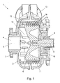
- a cavitation device 1 of the invention comprising a substantially cylindrical housing 2 having a flange connection 3 for connecting a feeding pipe for feeding liquid to the inside of the device.
- the housing 2 comprises an inlet opening 4 that opens centrally into the cavity of the housing and is aligned with the rotation axis 5 of the device 1.
- a stator arranged inside the housing 2 is denoted by 6 and defines a cylindrical cavity, in which a rotor 7 is arranged in a rotatable manner.
- the rotation axis of the rotor 7 is denoted by 5.
- the rotor 7 is supported on a shaft 8, which is arranged to rotate within a bearing 9.
- a sealing member is denoted by 10.
- the rotor carries a plurality of impeller blades 11, in order to direct fluid that enters the cavity through the inlet 4 radially outwardly towards the periphery of the rotor 7 and to the stator 6.
- the fluid is subjected to cavitation by cavitation elements of the rotor 7 and the stator 6, exits the stator 6 in a radial direction and is collected in an annular chamber 12 that surrounds the stator 6.
- the housing 2 comprises a tangential outlet opening 13, which serves to discharge the treated fluid.
- the impeller blades 11 of the rotor 7 are curved and extend to the peripheral region or the rotor 7.
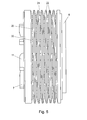
- the rotor 7 comprises a plurality of teeth 15 that are arranged at equal circumferential distances from each other, so that a chamber 16 is formed between each two subsequent teeth 15 in a row.
- the teeth 15 are arranged along the entire circumference of the rotor 7. Further, the teeth 15 are arranged in eight parallel, circular rows 14 of teeth.
- the rows 14 of teeth 15 are arranged concentrically and at the same radial distance from the rotation axis 5. An annular cavity is formed between each two adjacent rows 14.
- the stator 6 comprises a plurality of circular rows 17 of radially inwardly protruding teeth 18, wherein the teeth 18 of each row 17 are arranged at an equal circumferential distance to each other so that a chamber 19 is formed between each two subsequent teeth 18 in a row 17.
- the teeth 18 of the stator 6 are arranged to protrude into the annular cavity between two neighboring rows 14 of the rotor 7.
- the teeth 15 of the rotor 7 and the teeth 18 of the stator 6, in a longitudinal section as shown in Fig. 1 have a trapezoidal profile.
- the trapezoidal profile of the teeth 15 of the rotor 7 tapers in a radially outward direction and the trapezoidal profile of the teeth 18 of the stator 6 tapers in a radially inward direction.
- the profiles of the teeth 15 correspond to the profile of the annular cavity formed between two adjacent rows 19 of the teeth 18 and the profiles of the teeth 18 correspond to the profile of the annular cavity formed between two adjacent rows 14 of the teeth 15.
- the corresponding surfaces of the teeth and the annular cavity do not glide on each other, but the surfaces facing each other define a gap between them that allows fluid to flow therethrough.
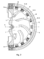
- a first rotational position of the rotor 7 as shown in Fig. 2 the teeth 15 of the rotor 7 and the teeth 18 of the stator 6 overlap each other, so that the respective chambers 16 and 19 are aligned in an axial direction thereby forming channels extending parallel to the rotation axis 5 of the rotor 7.
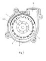
- the chambers 16 of the rows 14 get gradually closed on their sides by the teeth 18 of the stator 6 and the chambers 19 of the rows 17 get gradually closed on their sides by the teeth 15 of the rotor 7.
- Fig. 3 illustrates the beginning closing procedure, wherein the teeth 15 of the rotor 7 have left their position, in which they are axially aligned with the teeth 18 of the stator 6, and slightly project into the chambers 16,19.
- the chambers 19 of the stator 6 each have a discharge opening 20 directed radially outwardly.
- the discharge opening 20 is configured as a slit and has a circumferential extent that corresponds to the circumferential distance between two teeth 18 in a row 17.
- the discharge openings 20 each open into a discharge channel 21, that has a cross section that widens in an outward direction.
- the discharge channels 21 are defined between circumferential ribs 22 of the stator 6, wherein the ribs 21 taper in a radially outward direction.
- the rows 14 of the rotor 7 and the rows 17 of the stator 6 have an equal number of teeth 15,18.
- the rows 14 of the rotor 7 have one tooth 15 less than the rows 17 of the stator 6. Therefore, as illustrated in Fig. 6 , the teeth 15 of the rotor 7 and the teeth 18 of the stator 6 do not overlap each other to the same extent.
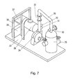
- the cavitation device 1 of the invention may be used in a system illustrated in Fig. 7 .
- the system comprises a supporting frame 23, which carries a pump 24, a mixing tank 25, a power cabinet 26, a control console equipped with a touch screen 27 and an electric engine 28. All components of the device are connected by a system of pipes 29.
- the pipes 29 are equipped with temperature measuring devices 30, pressure measuring devices 31, a flow meter 32, a protective screen 33 for the operator and other devices necessary for the measuring and defining the technical working parameters of the cavitational pump.
- phase (I) is conjugated with phase (III).
- the teeth 15 of the rotor 7 and the teeth 18 of the stator 6 are completely aligned in an axial direction (as shown in Fig. 2 ). In this position of the rotor 7 relative to the stator 6 axial channels are formed by the alignment of the chambers 16 and 19, through which the liquid moves. Further, in this position a gap is present between the surfaces of the teeth 15 and the teeth 18 facing each other. In this gap there is a sudden drop in pressure and caverns are formed.
- Characteristic of this phase is flow, accompanied by intensive mixing of liquid with pulsation of speeds and pressure in the narrow gaps. Along with the main longitudinal movement of liquid, a transversal movement and spinning motions of separate volumes of liquid are observed.
- Liquid flow moves along the discharge channels 21 for the outlet of treated liquid.
- the treated liquid is transferred from the discharge channels 21 into the annular cavity 12 and to the outlet opening 13 of the device.
- Teeth rows 14 of the rotor 7 additionally provide flow of liquid to the discharge channels 21 due to centrifugal forces. At low rotation speed of the rotor 7 and at low pressure, no visible change in the liquid movement in the discharge channels 21 is observed.
- a second zone of cavitation formation arises, with the formation of gas filled bubbles. A second area of local boiling is formed. i.e. the formation of steam with the release of gas which is dissolved in the water. The subsequent condensation and the implosion of caverns are accompanied by a hydraulic shock.
- the speed at which the liquid moves in the device can be altered by the rotation frequency of the rotor; pressure in the system can be altered, for example, by a stop valve which is placed at the inlet 4. In this way a controlled cavitational process is provided that safeguards the working organs from tear and wear.
- the productivity of the device is directly dependent on altering these parameters and the parameters of the processed liquid.
Landscapes
- Chemical & Material Sciences (AREA)
- Chemical Kinetics & Catalysis (AREA)
- Structures Of Non-Positive Displacement Pumps (AREA)
Priority Applications (1)
| Application Number | Priority Date | Filing Date | Title |
|---|---|---|---|
| EP15000878.7A EP3072579B1 (fr) | 2015-03-25 | 2015-03-25 | Dispositif de cavitation |
Applications Claiming Priority (1)
| Application Number | Priority Date | Filing Date | Title |
|---|---|---|---|
| EP15000878.7A EP3072579B1 (fr) | 2015-03-25 | 2015-03-25 | Dispositif de cavitation |
Publications (2)
| Publication Number | Publication Date |
|---|---|
| EP3072579A1 true EP3072579A1 (fr) | 2016-09-28 |
| EP3072579B1 EP3072579B1 (fr) | 2018-04-18 |
Family
ID=52780760
Family Applications (1)
| Application Number | Title | Priority Date | Filing Date |
|---|---|---|---|
| EP15000878.7A Not-in-force EP3072579B1 (fr) | 2015-03-25 | 2015-03-25 | Dispositif de cavitation |
Country Status (1)
| Country | Link |
|---|---|
| EP (1) | EP3072579B1 (fr) |
Cited By (8)
| Publication number | Priority date | Publication date | Assignee | Title |
|---|---|---|---|---|
| CN106724960A (zh) * | 2016-12-22 | 2017-05-31 | 浙江理工大学 | 一种空化增氧型果蔬清洗机 |
| CN106925147A (zh) * | 2017-03-22 | 2017-07-07 | 北京尤里卡兰超声空泡技术有限公司 | 一种流体动力转子式空化器 |
| CN111807497A (zh) * | 2020-07-31 | 2020-10-23 | 山东大学 | 一种基于水力空化的抗生素废水深度降解装置 |
| CN113562808A (zh) * | 2021-09-26 | 2021-10-29 | 中国海洋大学 | 一种对转水力空化系统 |
| US20210354098A1 (en) * | 2018-10-10 | 2021-11-18 | Three Es S.R.L. | Cavitation Reactor |
| CN113697972A (zh) * | 2021-08-13 | 2021-11-26 | 北京理工大学 | 一种非接触式可调节微纳米气泡发生器 |
| CN113952882A (zh) * | 2021-11-15 | 2022-01-21 | 大连海事大学 | 一种组合水力空化装置及其空化发生方法 |
| US20230027441A1 (en) * | 2019-12-17 | 2023-01-26 | Kujtim HYSENI | Cavitator for gas generation |
Citations (9)
| Publication number | Priority date | Publication date | Assignee | Title |
|---|---|---|---|---|
| US1487208A (en) * | 1922-12-13 | 1924-03-18 | Turbinator Company Inc | Agitating and mixing device |
| US3088712A (en) * | 1952-07-28 | 1963-05-07 | Coast Proseal & Mfg Co | Applicator and mixer for viscous materials |
| US4330215A (en) * | 1979-05-03 | 1982-05-18 | Rubber & Plastics Research Assoc Of Gb | Mixing device |
| RU2120471C1 (ru) | 1996-09-18 | 1998-10-20 | Борис Борисович Булгаков | Способ получения жидкого топлива и устройство для его изготовления |
| DE19720959A1 (de) * | 1997-05-17 | 1998-11-19 | Dorr Oliver Deutschland | Rotor-Stator-Maschine |
| RU2124935C1 (ru) | 1997-07-17 | 1999-01-20 | Филиппов Игорь Анатольевич | Роторно-пульсационный аппарат |
| RU2150318C1 (ru) | 1998-11-10 | 2000-06-10 | Тамбовский государственный технический университет | Роторный аппарат |
| RU2165787C1 (ru) | 1999-09-06 | 2001-04-27 | Тамбовский государственный технический университет | Роторный аппарат |
| RU2271245C1 (ru) | 2004-07-12 | 2006-03-10 | Андрей Дмитриевич Пинтюшенко | Роторно-пульсационный аппарат |
-
2015
- 2015-03-25 EP EP15000878.7A patent/EP3072579B1/fr not_active Not-in-force
Patent Citations (9)
| Publication number | Priority date | Publication date | Assignee | Title |
|---|---|---|---|---|
| US1487208A (en) * | 1922-12-13 | 1924-03-18 | Turbinator Company Inc | Agitating and mixing device |
| US3088712A (en) * | 1952-07-28 | 1963-05-07 | Coast Proseal & Mfg Co | Applicator and mixer for viscous materials |
| US4330215A (en) * | 1979-05-03 | 1982-05-18 | Rubber & Plastics Research Assoc Of Gb | Mixing device |
| RU2120471C1 (ru) | 1996-09-18 | 1998-10-20 | Борис Борисович Булгаков | Способ получения жидкого топлива и устройство для его изготовления |
| DE19720959A1 (de) * | 1997-05-17 | 1998-11-19 | Dorr Oliver Deutschland | Rotor-Stator-Maschine |
| RU2124935C1 (ru) | 1997-07-17 | 1999-01-20 | Филиппов Игорь Анатольевич | Роторно-пульсационный аппарат |
| RU2150318C1 (ru) | 1998-11-10 | 2000-06-10 | Тамбовский государственный технический университет | Роторный аппарат |
| RU2165787C1 (ru) | 1999-09-06 | 2001-04-27 | Тамбовский государственный технический университет | Роторный аппарат |
| RU2271245C1 (ru) | 2004-07-12 | 2006-03-10 | Андрей Дмитриевич Пинтюшенко | Роторно-пульсационный аппарат |
Cited By (14)
| Publication number | Priority date | Publication date | Assignee | Title |
|---|---|---|---|---|
| CN106724960A (zh) * | 2016-12-22 | 2017-05-31 | 浙江理工大学 | 一种空化增氧型果蔬清洗机 |
| CN106925147A (zh) * | 2017-03-22 | 2017-07-07 | 北京尤里卡兰超声空泡技术有限公司 | 一种流体动力转子式空化器 |
| US20210354098A1 (en) * | 2018-10-10 | 2021-11-18 | Three Es S.R.L. | Cavitation Reactor |
| US11491450B2 (en) * | 2018-10-10 | 2022-11-08 | Three Es S.R.L. | Cavitation reactor |
| US20230027441A1 (en) * | 2019-12-17 | 2023-01-26 | Kujtim HYSENI | Cavitator for gas generation |
| EP4077222A4 (fr) * | 2019-12-17 | 2024-02-28 | Kujtim Hyseni | Dispositif de cavitation pour génération de gaz |
| US20230356173A1 (en) * | 2019-12-17 | 2023-11-09 | Kujtim HYSENI | Gas generator and cavitator for gas generation |
| CN111807497A (zh) * | 2020-07-31 | 2020-10-23 | 山东大学 | 一种基于水力空化的抗生素废水深度降解装置 |
| CN113697972A (zh) * | 2021-08-13 | 2021-11-26 | 北京理工大学 | 一种非接触式可调节微纳米气泡发生器 |
| CN113697972B (zh) * | 2021-08-13 | 2022-06-03 | 北京理工大学 | 一种非接触式可调节微纳米气泡发生器 |
| CN113562808A (zh) * | 2021-09-26 | 2021-10-29 | 中国海洋大学 | 一种对转水力空化系统 |
| CN113562808B (zh) * | 2021-09-26 | 2022-02-18 | 中国海洋大学 | 一种对转水力空化系统 |
| CN113952882A (zh) * | 2021-11-15 | 2022-01-21 | 大连海事大学 | 一种组合水力空化装置及其空化发生方法 |
| CN113952882B (zh) * | 2021-11-15 | 2024-03-12 | 大连海事大学 | 一种组合水力空化装置及其空化发生方法 |
Also Published As
| Publication number | Publication date |
|---|---|
| EP3072579B1 (fr) | 2018-04-18 |
Similar Documents
| Publication | Publication Date | Title |
|---|---|---|
| EP3072579B1 (fr) | Dispositif de cavitation | |
| US11213793B2 (en) | Cavitation pump | |
| CN105683091A (zh) | 通过环形结构之间的空化来处理水的方法和设备 | |
| KR102898576B1 (ko) | 캐비테이션 반응기 | |
| EP1985357A1 (fr) | Procédé et appareil pour le traitement de liquides sous des conditions de cavitation | |
| RU2422733C1 (ru) | Тепловой кавитационный генератор | |
| RU2269075C1 (ru) | Кавитационно-вихревой теплогенератор | |
| RU2279018C1 (ru) | Вихревой теплогенератор гидросистемы | |
| RU2495337C2 (ru) | Электронасос центробежный герметичный - теплогенератор | |
| JP2013532252A (ja) | 複流渦巻ポンプ | |
| RU2433873C1 (ru) | Роторный, универсальный, кавитационный генератор-диспергатор | |
| RU2694774C1 (ru) | Роторный пульсационный аппарат | |
| RU138045U1 (ru) | Кавитационный гидроударный диспергатор | |
| RU2593728C1 (ru) | Газостабилизирующий насосный модуль (варианты) | |
| RU2166986C2 (ru) | Роторно-пульсационный аппарат (рпа) | |
| RU2329862C2 (ru) | Диспергатор-активатор | |
| RU2610802C1 (ru) | Рабочее колесо центробежного насоса | |
| RU2610803C1 (ru) | Рабочее колесо центробежного насоса | |
| RU2658448C1 (ru) | Многоступенчатый кавитационный теплогенератор (варианты) | |
| RU55302U1 (ru) | Роторно-пульсационный аппарат | |
| RU238303U1 (ru) | Диспергирующий роторный смеситель | |
| RU173223U1 (ru) | Дезинтегратор | |
| RU2397793C1 (ru) | Роторно-пульсационный экстрактор с направляющими лопастями | |
| RU116784U1 (ru) | Роторный импульсный аппарат | |
| RU2411423C2 (ru) | Способ получения парогазовой смеси и горячего теплоносителя из жидкости и турбороторный парогазогенератор для его осуществления |
Legal Events
| Date | Code | Title | Description |
|---|---|---|---|
| PUAI | Public reference made under article 153(3) epc to a published international application that has entered the european phase |
Free format text: ORIGINAL CODE: 0009012 |
|
| AK | Designated contracting states |
Kind code of ref document: A1 Designated state(s): AL AT BE BG CH CY CZ DE DK EE ES FI FR GB GR HR HU IE IS IT LI LT LU LV MC MK MT NL NO PL PT RO RS SE SI SK SM TR |
|
| AX | Request for extension of the european patent |
Extension state: BA ME |
|
| STAA | Information on the status of an ep patent application or granted ep patent |
Free format text: STATUS: REQUEST FOR EXAMINATION WAS MADE |
|
| 17P | Request for examination filed |
Effective date: 20170328 |
|
| RBV | Designated contracting states (corrected) |
Designated state(s): AL AT BE BG CH CY CZ DE DK EE ES FI FR GB GR HR HU IE IS IT LI LT LU LV MC MK MT NL NO PL PT RO RS SE SI SK SM TR |
|
| GRAP | Despatch of communication of intention to grant a patent |
Free format text: ORIGINAL CODE: EPIDOSNIGR1 |
|
| STAA | Information on the status of an ep patent application or granted ep patent |
Free format text: STATUS: GRANT OF PATENT IS INTENDED |
|
| INTG | Intention to grant announced |
Effective date: 20171102 |
|
| GRAS | Grant fee paid |
Free format text: ORIGINAL CODE: EPIDOSNIGR3 |
|
| RIN1 | Information on inventor provided before grant (corrected) |
Inventor name: VOLKOV, VITALIY Inventor name: LAKSA, ANDREJS |
|
| GRAA | (expected) grant |
Free format text: ORIGINAL CODE: 0009210 |
|
| STAA | Information on the status of an ep patent application or granted ep patent |
Free format text: STATUS: THE PATENT HAS BEEN GRANTED |
|
| RAP1 | Party data changed (applicant data changed or rights of an application transferred) |
Owner name: LAKSA, ANDREJS Owner name: VOLKOV, VITALIY |
|
| AK | Designated contracting states |
Kind code of ref document: B1 Designated state(s): AL AT BE BG CH CY CZ DE DK EE ES FI FR GB GR HR HU IE IS IT LI LT LU LV MC MK MT NL NO PL PT RO RS SE SI SK SM TR |
|
| REG | Reference to a national code |
Ref country code: GB Ref legal event code: FG4D |
|
| REG | Reference to a national code |
Ref country code: CH Ref legal event code: EP |
|
| REG | Reference to a national code |
Ref country code: AT Ref legal event code: REF Ref document number: 989843 Country of ref document: AT Kind code of ref document: T Effective date: 20180515 |
|
| REG | Reference to a national code |
Ref country code: IE Ref legal event code: FG4D |
|
| REG | Reference to a national code |
Ref country code: DE Ref legal event code: R096 Ref document number: 602015009988 Country of ref document: DE |
|
| REG | Reference to a national code |
Ref country code: NL Ref legal event code: MP Effective date: 20180418 |
|
| REG | Reference to a national code |
Ref country code: LT Ref legal event code: MG4D |
|
| PG25 | Lapsed in a contracting state [announced via postgrant information from national office to epo] |
Ref country code: NL Free format text: LAPSE BECAUSE OF FAILURE TO SUBMIT A TRANSLATION OF THE DESCRIPTION OR TO PAY THE FEE WITHIN THE PRESCRIBED TIME-LIMIT Effective date: 20180418 |
|
| PG25 | Lapsed in a contracting state [announced via postgrant information from national office to epo] |
Ref country code: SE Free format text: LAPSE BECAUSE OF FAILURE TO SUBMIT A TRANSLATION OF THE DESCRIPTION OR TO PAY THE FEE WITHIN THE PRESCRIBED TIME-LIMIT Effective date: 20180418 Ref country code: AL Free format text: LAPSE BECAUSE OF FAILURE TO SUBMIT A TRANSLATION OF THE DESCRIPTION OR TO PAY THE FEE WITHIN THE PRESCRIBED TIME-LIMIT Effective date: 20180418 Ref country code: FI Free format text: LAPSE BECAUSE OF FAILURE TO SUBMIT A TRANSLATION OF THE DESCRIPTION OR TO PAY THE FEE WITHIN THE PRESCRIBED TIME-LIMIT Effective date: 20180418 Ref country code: BG Free format text: LAPSE BECAUSE OF FAILURE TO SUBMIT A TRANSLATION OF THE DESCRIPTION OR TO PAY THE FEE WITHIN THE PRESCRIBED TIME-LIMIT Effective date: 20180718 Ref country code: NO Free format text: LAPSE BECAUSE OF FAILURE TO SUBMIT A TRANSLATION OF THE DESCRIPTION OR TO PAY THE FEE WITHIN THE PRESCRIBED TIME-LIMIT Effective date: 20180718 Ref country code: LT Free format text: LAPSE BECAUSE OF FAILURE TO SUBMIT A TRANSLATION OF THE DESCRIPTION OR TO PAY THE FEE WITHIN THE PRESCRIBED TIME-LIMIT Effective date: 20180418 Ref country code: PL Free format text: LAPSE BECAUSE OF FAILURE TO SUBMIT A TRANSLATION OF THE DESCRIPTION OR TO PAY THE FEE WITHIN THE PRESCRIBED TIME-LIMIT Effective date: 20180418 Ref country code: ES Free format text: LAPSE BECAUSE OF FAILURE TO SUBMIT A TRANSLATION OF THE DESCRIPTION OR TO PAY THE FEE WITHIN THE PRESCRIBED TIME-LIMIT Effective date: 20180418 |
|
| PG25 | Lapsed in a contracting state [announced via postgrant information from national office to epo] |
Ref country code: GR Free format text: LAPSE BECAUSE OF FAILURE TO SUBMIT A TRANSLATION OF THE DESCRIPTION OR TO PAY THE FEE WITHIN THE PRESCRIBED TIME-LIMIT Effective date: 20180719 Ref country code: LV Free format text: LAPSE BECAUSE OF FAILURE TO SUBMIT A TRANSLATION OF THE DESCRIPTION OR TO PAY THE FEE WITHIN THE PRESCRIBED TIME-LIMIT Effective date: 20180418 Ref country code: HR Free format text: LAPSE BECAUSE OF FAILURE TO SUBMIT A TRANSLATION OF THE DESCRIPTION OR TO PAY THE FEE WITHIN THE PRESCRIBED TIME-LIMIT Effective date: 20180418 Ref country code: RS Free format text: LAPSE BECAUSE OF FAILURE TO SUBMIT A TRANSLATION OF THE DESCRIPTION OR TO PAY THE FEE WITHIN THE PRESCRIBED TIME-LIMIT Effective date: 20180418 |
|
| REG | Reference to a national code |
Ref country code: AT Ref legal event code: MK05 Ref document number: 989843 Country of ref document: AT Kind code of ref document: T Effective date: 20180418 |
|
| PG25 | Lapsed in a contracting state [announced via postgrant information from national office to epo] |
Ref country code: PT Free format text: LAPSE BECAUSE OF FAILURE TO SUBMIT A TRANSLATION OF THE DESCRIPTION OR TO PAY THE FEE WITHIN THE PRESCRIBED TIME-LIMIT Effective date: 20180820 |
|
| REG | Reference to a national code |
Ref country code: DE Ref legal event code: R097 Ref document number: 602015009988 Country of ref document: DE |
|
| PG25 | Lapsed in a contracting state [announced via postgrant information from national office to epo] |
Ref country code: RO Free format text: LAPSE BECAUSE OF FAILURE TO SUBMIT A TRANSLATION OF THE DESCRIPTION OR TO PAY THE FEE WITHIN THE PRESCRIBED TIME-LIMIT Effective date: 20180418 Ref country code: AT Free format text: LAPSE BECAUSE OF FAILURE TO SUBMIT A TRANSLATION OF THE DESCRIPTION OR TO PAY THE FEE WITHIN THE PRESCRIBED TIME-LIMIT Effective date: 20180418 Ref country code: CZ Free format text: LAPSE BECAUSE OF FAILURE TO SUBMIT A TRANSLATION OF THE DESCRIPTION OR TO PAY THE FEE WITHIN THE PRESCRIBED TIME-LIMIT Effective date: 20180418 Ref country code: EE Free format text: LAPSE BECAUSE OF FAILURE TO SUBMIT A TRANSLATION OF THE DESCRIPTION OR TO PAY THE FEE WITHIN THE PRESCRIBED TIME-LIMIT Effective date: 20180418 Ref country code: DK Free format text: LAPSE BECAUSE OF FAILURE TO SUBMIT A TRANSLATION OF THE DESCRIPTION OR TO PAY THE FEE WITHIN THE PRESCRIBED TIME-LIMIT Effective date: 20180418 Ref country code: SK Free format text: LAPSE BECAUSE OF FAILURE TO SUBMIT A TRANSLATION OF THE DESCRIPTION OR TO PAY THE FEE WITHIN THE PRESCRIBED TIME-LIMIT Effective date: 20180418 |
|
| PLBE | No opposition filed within time limit |
Free format text: ORIGINAL CODE: 0009261 |
|
| STAA | Information on the status of an ep patent application or granted ep patent |
Free format text: STATUS: NO OPPOSITION FILED WITHIN TIME LIMIT |
|
| PG25 | Lapsed in a contracting state [announced via postgrant information from national office to epo] |
Ref country code: SM Free format text: LAPSE BECAUSE OF FAILURE TO SUBMIT A TRANSLATION OF THE DESCRIPTION OR TO PAY THE FEE WITHIN THE PRESCRIBED TIME-LIMIT Effective date: 20180418 Ref country code: IT Free format text: LAPSE BECAUSE OF FAILURE TO SUBMIT A TRANSLATION OF THE DESCRIPTION OR TO PAY THE FEE WITHIN THE PRESCRIBED TIME-LIMIT Effective date: 20180418 |
|
| 26N | No opposition filed |
Effective date: 20190121 |
|
| PG25 | Lapsed in a contracting state [announced via postgrant information from national office to epo] |
Ref country code: SI Free format text: LAPSE BECAUSE OF FAILURE TO SUBMIT A TRANSLATION OF THE DESCRIPTION OR TO PAY THE FEE WITHIN THE PRESCRIBED TIME-LIMIT Effective date: 20180418 |
|
| PG25 | Lapsed in a contracting state [announced via postgrant information from national office to epo] |
Ref country code: MC Free format text: LAPSE BECAUSE OF FAILURE TO SUBMIT A TRANSLATION OF THE DESCRIPTION OR TO PAY THE FEE WITHIN THE PRESCRIBED TIME-LIMIT Effective date: 20180418 |
|
| REG | Reference to a national code |
Ref country code: CH Ref legal event code: PL |
|
| GBPC | Gb: european patent ceased through non-payment of renewal fee |
Effective date: 20190325 |
|
| PG25 | Lapsed in a contracting state [announced via postgrant information from national office to epo] |
Ref country code: LU Free format text: LAPSE BECAUSE OF NON-PAYMENT OF DUE FEES Effective date: 20190325 |
|
| REG | Reference to a national code |
Ref country code: BE Ref legal event code: MM Effective date: 20190331 |
|
| PG25 | Lapsed in a contracting state [announced via postgrant information from national office to epo] |
Ref country code: GB Free format text: LAPSE BECAUSE OF NON-PAYMENT OF DUE FEES Effective date: 20190325 Ref country code: IE Free format text: LAPSE BECAUSE OF NON-PAYMENT OF DUE FEES Effective date: 20190325 Ref country code: CH Free format text: LAPSE BECAUSE OF NON-PAYMENT OF DUE FEES Effective date: 20190331 Ref country code: LI Free format text: LAPSE BECAUSE OF NON-PAYMENT OF DUE FEES Effective date: 20190331 |
|
| PG25 | Lapsed in a contracting state [announced via postgrant information from national office to epo] |
Ref country code: FR Free format text: LAPSE BECAUSE OF NON-PAYMENT OF DUE FEES Effective date: 20190331 Ref country code: BE Free format text: LAPSE BECAUSE OF NON-PAYMENT OF DUE FEES Effective date: 20190331 |
|
| PG25 | Lapsed in a contracting state [announced via postgrant information from national office to epo] |
Ref country code: TR Free format text: LAPSE BECAUSE OF FAILURE TO SUBMIT A TRANSLATION OF THE DESCRIPTION OR TO PAY THE FEE WITHIN THE PRESCRIBED TIME-LIMIT Effective date: 20180418 |
|
| PGFP | Annual fee paid to national office [announced via postgrant information from national office to epo] |
Ref country code: DE Payment date: 20200327 Year of fee payment: 6 |
|
| PG25 | Lapsed in a contracting state [announced via postgrant information from national office to epo] |
Ref country code: MT Free format text: LAPSE BECAUSE OF NON-PAYMENT OF DUE FEES Effective date: 20190325 |
|
| PG25 | Lapsed in a contracting state [announced via postgrant information from national office to epo] |
Ref country code: CY Free format text: LAPSE BECAUSE OF FAILURE TO SUBMIT A TRANSLATION OF THE DESCRIPTION OR TO PAY THE FEE WITHIN THE PRESCRIBED TIME-LIMIT Effective date: 20180418 |
|
| PG25 | Lapsed in a contracting state [announced via postgrant information from national office to epo] |
Ref country code: IS Free format text: LAPSE BECAUSE OF FAILURE TO SUBMIT A TRANSLATION OF THE DESCRIPTION OR TO PAY THE FEE WITHIN THE PRESCRIBED TIME-LIMIT Effective date: 20180818 |
|
| PG25 | Lapsed in a contracting state [announced via postgrant information from national office to epo] |
Ref country code: HU Free format text: LAPSE BECAUSE OF FAILURE TO SUBMIT A TRANSLATION OF THE DESCRIPTION OR TO PAY THE FEE WITHIN THE PRESCRIBED TIME-LIMIT; INVALID AB INITIO Effective date: 20150325 |
|
| REG | Reference to a national code |
Ref country code: DE Ref legal event code: R119 Ref document number: 602015009988 Country of ref document: DE |
|
| PG25 | Lapsed in a contracting state [announced via postgrant information from national office to epo] |
Ref country code: DE Free format text: LAPSE BECAUSE OF NON-PAYMENT OF DUE FEES Effective date: 20211001 |
|
| PG25 | Lapsed in a contracting state [announced via postgrant information from national office to epo] |
Ref country code: MK Free format text: LAPSE BECAUSE OF FAILURE TO SUBMIT A TRANSLATION OF THE DESCRIPTION OR TO PAY THE FEE WITHIN THE PRESCRIBED TIME-LIMIT Effective date: 20180418 |