EP3072581A2 - Verfahren und vorrichtung zur herstellung von aufgeschäumter lebensmittelmasse mit stücken oder aroma - Google Patents
Verfahren und vorrichtung zur herstellung von aufgeschäumter lebensmittelmasse mit stücken oder aroma Download PDFInfo
- Publication number
- EP3072581A2 EP3072581A2 EP16160400.4A EP16160400A EP3072581A2 EP 3072581 A2 EP3072581 A2 EP 3072581A2 EP 16160400 A EP16160400 A EP 16160400A EP 3072581 A2 EP3072581 A2 EP 3072581A2
- Authority
- EP
- European Patent Office
- Prior art keywords
- stator housing
- food
- rotor
- pressure
- inlet
- Prior art date
- Legal status (The legal status is an assumption and is not a legal conclusion. Google has not performed a legal analysis and makes no representation as to the accuracy of the status listed.)
- Granted
Links
Images

Classifications
-
- C—CHEMISTRY; METALLURGY
- C12—BIOCHEMISTRY; BEER; SPIRITS; WINE; VINEGAR; MICROBIOLOGY; ENZYMOLOGY; MUTATION OR GENETIC ENGINEERING
- C12G—WINE; PREPARATION THEREOF; ALCOHOLIC BEVERAGES; PREPARATION OF ALCOHOLIC BEVERAGES NOT PROVIDED FOR IN SUBCLASSES C12C OR C12H
- C12G3/00—Preparation of other alcoholic beverages
- C12G3/04—Preparation of other alcoholic beverages by mixing, e.g. for preparation of liqueurs
-
- A—HUMAN NECESSITIES
- A23—FOODS OR FOODSTUFFS; TREATMENT THEREOF, NOT COVERED BY OTHER CLASSES
- A23C—DAIRY PRODUCTS, e.g. MILK, BUTTER OR CHEESE; MILK OR CHEESE SUBSTITUTES; PREPARATION THEREOF
- A23C13/00—Cream; Cream preparations; Making thereof
- A23C13/12—Cream preparations
-
- A—HUMAN NECESSITIES
- A23—FOODS OR FOODSTUFFS; TREATMENT THEREOF, NOT COVERED BY OTHER CLASSES
- A23G—COCOA; COCOA PRODUCTS, e.g. CHOCOLATE; SUBSTITUTES FOR COCOA OR COCOA PRODUCTS; CONFECTIONERY; CHEWING GUM; ICE-CREAM; PREPARATION THEREOF
- A23G3/00—Sweetmeats; Confectionery; Marzipan; Coated or filled products
- A23G3/34—Sweetmeats, confectionery or marzipan; Processes for the preparation thereof
- A23G3/50—Sweetmeats, confectionery or marzipan; Processes for the preparation thereof characterised by shape, structure or physical form, e.g. products with supported structure
- A23G3/52—Aerated, foamed, cellular or porous products
-
- A—HUMAN NECESSITIES
- A23—FOODS OR FOODSTUFFS; TREATMENT THEREOF, NOT COVERED BY OTHER CLASSES
- A23G—COCOA; COCOA PRODUCTS, e.g. CHOCOLATE; SUBSTITUTES FOR COCOA OR COCOA PRODUCTS; CONFECTIONERY; CHEWING GUM; ICE-CREAM; PREPARATION THEREOF
- A23G3/00—Sweetmeats; Confectionery; Marzipan; Coated or filled products
- A23G3/34—Sweetmeats, confectionery or marzipan; Processes for the preparation thereof
- A23G3/50—Sweetmeats, confectionery or marzipan; Processes for the preparation thereof characterised by shape, structure or physical form, e.g. products with supported structure
- A23G3/54—Composite products, e.g. layered, coated, filled
-
- A—HUMAN NECESSITIES
- A23—FOODS OR FOODSTUFFS; TREATMENT THEREOF, NOT COVERED BY OTHER CLASSES
- A23P—SHAPING OR WORKING OF FOODSTUFFS, NOT FULLY COVERED BY A SINGLE OTHER SUBCLASS
- A23P30/00—Shaping or working of foodstuffs characterised by the process or apparatus
- A23P30/40—Foaming or whipping
-
- B—PERFORMING OPERATIONS; TRANSPORTING
- B01—PHYSICAL OR CHEMICAL PROCESSES OR APPARATUS IN GENERAL
- B01F—MIXING, e.g. DISSOLVING, EMULSIFYING OR DISPERSING
- B01F23/00—Mixing according to the phases to be mixed, e.g. dispersing or emulsifying
- B01F23/20—Mixing gases with liquids
- B01F23/23—Mixing gases with liquids by introducing gases into liquid media, e.g. for producing aerated liquids
- B01F23/235—Mixing gases with liquids by introducing gases into liquid media, e.g. for producing aerated liquids for making foam
- B01F23/2351—Mixing gases with liquids by introducing gases into liquid media, e.g. for producing aerated liquids for making foam using driven stirrers
-
- B—PERFORMING OPERATIONS; TRANSPORTING
- B01—PHYSICAL OR CHEMICAL PROCESSES OR APPARATUS IN GENERAL
- B01F—MIXING, e.g. DISSOLVING, EMULSIFYING OR DISPERSING
- B01F23/00—Mixing according to the phases to be mixed, e.g. dispersing or emulsifying
- B01F23/50—Mixing liquids with solids
- B01F23/56—Mixing liquids with solids by introducing solids in liquids, e.g. dispersing or dissolving
-
- B—PERFORMING OPERATIONS; TRANSPORTING
- B01—PHYSICAL OR CHEMICAL PROCESSES OR APPARATUS IN GENERAL
- B01F—MIXING, e.g. DISSOLVING, EMULSIFYING OR DISPERSING
- B01F27/00—Mixers with rotary stirring devices in fixed receptacles; Kneaders
- B01F27/27—Mixers with stator-rotor systems, e.g. with intermeshing teeth or cylinders or having orifices
- B01F27/272—Mixers with stator-rotor systems, e.g. with intermeshing teeth or cylinders or having orifices with means for moving the materials to be mixed axially between the surfaces of the rotor and the stator, e.g. the stator rotor system formed by conical or cylindrical surfaces
- B01F27/2721—Mixers with stator-rotor systems, e.g. with intermeshing teeth or cylinders or having orifices with means for moving the materials to be mixed axially between the surfaces of the rotor and the stator, e.g. the stator rotor system formed by conical or cylindrical surfaces provided with intermeshing elements
-
- B—PERFORMING OPERATIONS; TRANSPORTING
- B01—PHYSICAL OR CHEMICAL PROCESSES OR APPARATUS IN GENERAL
- B01F—MIXING, e.g. DISSOLVING, EMULSIFYING OR DISPERSING
- B01F33/00—Other mixers; Mixing plants; Combinations of mixers
- B01F33/80—Mixing plants; Combinations of mixers
- B01F33/81—Combinations of similar mixers, e.g. with rotary stirring devices in two or more receptacles
- B01F33/811—Combinations of similar mixers, e.g. with rotary stirring devices in two or more receptacles in two or more consecutive, i.e. successive, mixing receptacles or being consecutively arranged
-
- B—PERFORMING OPERATIONS; TRANSPORTING
- B01—PHYSICAL OR CHEMICAL PROCESSES OR APPARATUS IN GENERAL
- B01F—MIXING, e.g. DISSOLVING, EMULSIFYING OR DISPERSING
- B01F35/00—Accessories for mixers; Auxiliary operations or auxiliary devices; Parts or details of general application
- B01F35/71—Feed mechanisms
- B01F35/715—Feeding the components in several steps, e.g. successive steps
-
- A—HUMAN NECESSITIES
- A23—FOODS OR FOODSTUFFS; TREATMENT THEREOF, NOT COVERED BY OTHER CLASSES
- A23C—DAIRY PRODUCTS, e.g. MILK, BUTTER OR CHEESE; MILK OR CHEESE SUBSTITUTES; PREPARATION THEREOF
- A23C2210/00—Physical treatment of dairy products
- A23C2210/30—Whipping, foaming, frothing or aerating dairy products
Definitions
- the invention relates to a process and an apparatus for the continuous production of frothed first foodstuff which has a second blended food which is not to be whipped up, in particular pieces of a second solid food which is insoluble in the first foodstuff.
- the first food mass can be whipped up with gas, for example air or nitrogen, to form a foam, in particular an aqueous protein-containing composition, eg containing protein, eg milk protein, egg white, gelatin solution, preferably cream, pudding, optionally with a flavor content , Sweetener, spice and / or dye.
- the first foodstuff contains a thickening agent and / or foam stabilizer, for example from the group comprising protein, eg gelatin (eg from cattle and / or pig) and milk protein, and / or polysaccharides, eg carrageenan, alginate, guar gum, native starch, modified starch, pectin, locust bean gum, and / or xanthan, and mixtures thereof, or consists thereof.
- the first food may contain at least one emulsifier, for example lactic acid esters of mono- and diglycerides of fatty acids, in particular palm oil fatty acids.
- the second food is distributed in the process as a lumpy ingredient in the foamed first food mass and is insoluble in the first food mass.
- the second food may be liquid, e.g. an alcoholic beverage which forms a flavor, e.g. Fruit brandy, liqueur, eggnog, alcohol-based flavor, liquid dye composition, juice or juice concentrate, e.g. fruit and fruits, yoghurt, milk protein and / or microbiological cultures, e.g. Lactobacilli.
- the chunky second food is chocolate, a fatty and / or cocoa-containing product, e.g. C curse, pieces of nuts, berries, preferably dried, cooked rice or a combination thereof, wherein the second food may be untreated or treated.
- the EP 0818150 A2 describes a tempering machine for chocolate with a plurality of successively flowed through chambers, which are formed by radial walls within a cylinder, in each of which a disc rotates, wherein between the chambers, a portion forms a Aufschlagkin with rotating striking elements and gas supply.
- the EP 0141991 A1 shows a cooker for candy mass, at its evaporation and discharge a screw conveyor connects, which has sections mixing elements to mix supplied gas.
- the WO 02/37977 A1 describes the batch-wise whipping of cream and the subsequent stirring of a hot aqueous gelatin solution and other foods by means of a food processor with whisk.
- the DE 3418338 A1 describes the foaming of eg cream by pressing with gas and subsequent expansion into a dispersion tube.
- the US 2 197 919 A shows a continuous process for the preparation of foamed candy mass by continuously pumping the mass and compressed air into a stator housing having radially and axially spaced impact members on the rotor and thus intermeshing static impact members on the stator.
- the leaking open mass is continuously fed through a pipeline to a mixer in which gum mass is continuously pumped and which can run at a lower RPM.
- the object of the invention is to provide an alternative method and an alternative apparatus for producing a foamed first food mass with distributed therein second food, which may be liquid, preferably lumpy.
- the method is preferably to produce a frothed first food with lumpy second food dispersed therein which is stable.
- the invention achieves the object with the features of the claims, in particular by a continuous method and an apparatus for use for producing foamed first food mass having a content of a second food, by continuously introducing the first food mass into a first stator housing and impacting in the first Stator housing, which is provided with radially and axially spaced static impact elements, by means of a first rotor in the first rotating rotor, which is provided with radially and axially spaced rotor striking elements which mesh with the static impact elements.
- the first stator housing is pressurized with a supplied gas and a continuous overpressure in the first stator housing is held to the outlet of a second stator housing connected thereto.
- the rotation of the rotor in the first stator housing leads to the production of a first opened food mass.
- the whipped first food mass and the second food are continuously fed to a second stator housing and mixed therein in the first whipped food mass, wherein the pressure is also held in the second stator housing.
- the opened first food mass and the second food which are continuously introduced into the second stator housing, which is provided with radially and axially spaced static mixing elements, by means of one in the second Stator housing rotating second rotor mixed, which is provided with radially and axially spaced rotor mixing elements which mesh with the static mixing elements.
- the open first food mass is continuously moved from the first stator housing in the second stator without the open first food mass undergoes a significant pressure drop through the flow path with subsequent pressure increase.
- the method has the advantage of continuously producing from a first food mass a foam having second food dispersed therein which is stable. This is particularly an advantage if the second food is lumpy or liquid and would escape during mixing under normal pressure, the impact of the first food and / or the mixing would produce an unstable foam.
- the static impact elements and / or the rotor impact elements may have a round or preferably an angular, e.g. square, have cross section.
- the static mixing elements and the rotor mixing elements may have a polygonal cross section, e.g. square, or have a round cross-section. Blending elements of round cross-section may damage the second food, if it is lumpy, less than those of square cross-section and may therefore be preferred.
- the rotor mixing elements and static mixing elements are arranged at a greater axial and radial distance from each other than the largest diameter of the pieces of the second food is.
- the first stator housing preferably has an inlet for the first food mass at its first end and an outlet for opened first food mass at the opposite second end.
- the inlet for the first food mass may be axially disposed on the first stator housing, e.g. adjacent to a bushing for the first shaft.
- the positive pressure gas inlet may be connected to the first food mass inlet such that the first stator housing may have only one first food mass inlet in mixture with the gas.
- the first food mass, the pressurized gas and the second food and any additives are sterile and the process is sterile and results in a sterile product.
- the first food mass and the second food, including any additives, for example UHT and eg shaft passages are designed as double mechanical seals whose space is subjected to a separation medium, eg steam.
- the second foodstuff may be suspended in a liquid carrier medium, e.g. an aqueous sugar solution, e.g. with fruit content, optionally with a content of thickener.
- a liquid carrier medium e.g. an aqueous sugar solution, e.g. with fruit content, optionally with a content of thickener.
- the liquid carrier medium is pumpable. Therefore, the second foodstuff, when suspended in a carrier medium or liquid, can be metered continuously into the whipped first food mass by means of a second pump with overpressure relative to the pressure within the apparatus, preferably with less pulsation.
- a positive displacement pump can be used as a metering device, which is connected by means of a second supply line to the connecting line or the second inlet of the second stator housing.
- the second food if it is particulate, may be without a liquid carrier medium, e.g. be dosed as pourable or pourable chunky food in the whipped first food mass.
- a screw conveyor, a chamber or a piston can be used as a metering device.
- the pressure in the first stator housing and in the second stator housing and a connecting conduit arranged between the first and second stator housings is maintained substantially at a predetermined pressure, e.g. with a variation of at most 20%, more preferably at most 10%, or at most 2% to 5% continuously maintained by a predetermined pressure.
- a pressure-maintaining valve is arranged to maintain the pressure.
- the pressure-holding valve may be part of a metering device connected to the second stator housing.
- the device has a connecting line between the first stator housing and the second stator housing.
- the pressure within the first stator housing, the connection line and within the second stator housing is e.g. preferably thereby maintains substantially at a predetermined value, that the supplied pressurized gas keeps the internal pressure of the device substantially constant and optionally in that the clear cross section of the first annular gap formed between the first rotor and the first stator housing, the clear Cross-section of the connecting line and the clear cross-section of the second annular gap, which is formed between the second rotor and the second stator housing, have approximately the same size, eg except for a deviation of not more than 200% or 50%, preferably not more than 20%, more preferably up to a deviation of not more than 10% have the same size.
- the clear cross-section of the connection line may have an amount of 50 to 200% of the amount of the clear cross section between the first rotor and the first stator housing and 50% to 200% of the amount of the clear cross section between the second rotor and the second stator housing.
- the apparatus preferably includes a pressure transducer connected to the first supply line connected to the inlet for the first food mass and the supply for the gas is arranged to maintain a predetermined gas overpressure within the device.
- the feed for the gas is e.g. controlled by the pressure transducer to maintain a predetermined overpressure within the device.
- the outlet of the first stator housing may be formed by its cross-sectional opening and / or the inlet of the second stator housing by its cross-sectional opening, to minimize pressure changes that the whipped first food mass undergoes as it passes through that outlet and inlet.
- the introduction or movement of the whipped first food mass from the first into the second stator housing takes place while maintaining the pressure in both stator housings, preferably by means of a line which has no enlargement and reduction or no reduction or enlargement of the cross section between the stator housings.
- Such a line can eg have a constant cross section which is equal to the clear cross section between the rotor and the first and second stator housing or a cross section which changes continuously, eg with a constant change over the length, between the clear cross section between the rotor and the first and second stator housing to connect these without steps.
- the first stator housing is connected to the second stator housing by virtue of the outlet of the first stator housing formed by the cross-sectional opening being directly connected to the inlet of the second stator housing formed by the cross-sectional opening, wherein the first and second stator housings have the same cross-section.
- the first and the second stator housing may be adjacent portions of a common stator housing.
- the movement or flow of the first food mass is preferably driven solely by the pressure of the first stator housing supplied gas and the supplied first food mass, optionally additionally by gravity, so that the impact elements have no conveying effect in the longitudinal direction of the stator housing and the rotor.
- the striking elements are e.g. Spikes that protrude radially from a rotor shaft or from the Statorgekoruseinnenwand. Accordingly, the first food mass can be conveyed to the pressure-maintaining valve solely by a pressure gradient between the continuously supplied gas of the continuously fed first food mass and the pressure-maintaining valve.
- the first rotor and / or the second rotor has no element with a conveying effect.
- the first rotor and / or the second rotor may include a conveying element to assist in conveying the first food mass through the first and second stator housings.
- a conveying element may e.g. to be a paddle wheel.
- the first stator housing may optionally have an inlet for the first food mass at its first end and an opening at its second end opposite the first end which extends over its entire cross section and which forms an outlet for the opened first food mass.
- the first stator housing also has an inlet for the pressurized gas, which is preferably disposed at the first end of the first stator housing.
- a nozzle is arranged on the first stator housing as the inlet for gas under overpressure, the nozzle preferably having a non-return valve in order to reduce the entry of first food mass into the connected gas feed line in the event of a pressure loss.
- the nozzle is e.g. arranged on the first line.
- the second stator housing has at its first end an inlet for open first food mass, which is formed by the cross-sectional area of the second stator housing. At its second end opposite the first end, the second stator housing has an outlet for the mixture of whipped first food and the second food. To maintain the gas pressure within the first and second stator housings, this outlet has a pressure holding valve so that the mixture can be released from the second stator housing without loss of gas pressure in the first and second stator housings.
- the pressure hold valve may be controlled responsive to the pressure transducer to maintain a predetermined positive pressure within the device.
- the connecting line or the second stator housing has an inlet for the lumpy second food, optionally at the top of the connecting line or on the stator housing, to allow the second food to fall under gravity into the second stator housing.
- a storage container for the second food is connected by means of a conduit and a metering device.
- the reservoir is optionally pressurized with compressed gas, preferably with the gas and at the pressure supplied to the first stator housing.
- the first rotor may be arranged along the same axis of rotation as the second rotor.
- the first rotor may be arranged on the same shaft as the second rotor.
- the first and the second rotor are each arranged on separate shafts, which are each driven by a motor.
- a separate drive for each rotor has the advantage that in Method, the speed of the first rotor can be set to strike regardless of the speed of the second rotor for mixing.
- the rotors are mounted on one side, the first rotor at its first end, which is opposite to its cross-sectional opening at the second end, and the second rotor at its second end, which is opposite to its cross-sectional opening at the first end.
- the first shaft of the first rotor is supported at the first end of the first stator housing and the inlet for the first food mass is mixed with the overpressure gas at that first end, preferably adjacent to or around the inlet the first shaft in the first stator housing, wherein more preferably, the outlet of the first stator housing is arranged at an axial distance from the first shaft, optionally along the axis of rotation of the first shaft in the first stator housing is formed.
- the cross-sectional opening at the second end of the first stator housing forms its outlet.
- the second shaft of the second rotor is preferably mounted on one side on the second end of the second stator housing.
- the inlet is disposed at the first end of the second stator housing at an axial distance from the second shaft, optionally formed along the axis of rotation of the second shaft in the second stator housing.
- the cross-sectional opening at the first end of the second stator housing forms its inlet.
- the method allows, at least for cream, pudding or protein foam, eg egg white foam, as the first food mass, the production of a foam with second food distributed therein, optionally without a content of the first food mass of foam stabilizer.
- Preference is given to the static impact elements and the Rotor striking elements arranged at a smaller axial and / or smaller radial distance than the static mixing elements and the rotor mixing elements.
- the first and second stator housings are preferably subjected to a gas pressure of at least 0.5 bar, preferably at least 1 bar overpressure, e.g. up to 8 bar.
- the gas is sterile and / or filtered, in particular nitrogen and / or air.
- the device according to the invention is intended for use in the method and has a first stator housing, which is provided with radially and axially spaced first static impact elements, and a first rotor rotating in the first stator housing, which is provided with radially and axially spaced rotor striking elements with comb the static impact elements.
- the first stator housing has an inlet for the first food and an inlet for the compressed gas, which are preferably arranged at the first end of the first stator housing, which is opposite to the second end, on which the outlet is arranged.
- the first stator housing is pressure-tightly connected to the second stator housing by connecting the outlet of the first stator housing to the inlet of the second stator housing and pressurizing and / or pumping the supply lines with gas and the pressure-maintaining valve at the outlet of the second stator housing ,
- the second stator housing is provided with radially and axially spaced static mixing elements and has a second rotor provided with radially and axially spaced rotor mixing elements which mesh with the static mixing elements.
- the inlet of the second stator housing is formed by an inlet at the first end and is connected by a conduit or directly to the outlet of the first stator housing. In the region of the first end, the second stator housing has the inlet for the lumpy second food. Opposite the first end is an outlet for the whipped first food mass having distributed therein second food.
- first and second stator housings are preferably cooled in the process, for example to a temperature of from 3 to 10 ° C.
- both stator housing can be in a cooling chamber or, preferably, have a cooling jacket.
- the cooling jacket is flowed through, for example, with cooling medium at a temperature of 1 to 3 ° C.
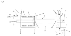
- the FIG. 1 shows a first stator housing 1, projecting from the inner wall static impact elements 2, which are radially and axially spaced from each other, are arranged radially to the central axis M of the first stator housing 1 and mesh with the rotor striking elements 3, radially and axially spaced from the first rotor 4 protrude radially ,
- the first stator housing 1 has an inlet 5 for pressurized gas and at its first end 6 an inlet 7 for the first food mass.
- the inlet for compressed gas and the inlet 7 for the first food mass are connected to the inlet 7 by means of a common supply line 24.
- the outlet of the first stator housing 1 is formed by its cross-sectional opening 8, which lies opposite the first end 6 at the second end 9 of the first stator housing 1.
- the outlet formed by the cross-sectional opening 8 is directly connected to the inlet formed by the cross-sectional opening 10 at the first end 11 of the second stator housing 12.
- the inlet at the first end 11 of the second stator housing 12 has the same cross-section as the outlet at the second end 9 of the first stator housing 1, so that pressure changes are avoided when the first food mass is transferred from the first stator housing 1 into the second stator housing 12.
- the second stator housing 12 has at its first end 11 an inlet 13 for the lumpy second food, so that the flowing first food mass, in the FIG.
- an outlet 18 is arranged for the outlet of the mixture of whipped first food mass with second food distributed therein.
- the outlet 18 can be closed by a pressure-retaining valve 19 which is controlled as a function of the internal pressure in the first and second stator housings 1, 12.
- the first stator housing 1 has a double jacket 20 as a cooling device, the second stator housing 12 a double jacket 21 as a cooling device.
- the first rotor 4 is mounted on one side on a first shaft 22 at the first end 6 of the first stator housing 1, the second one Rotor 16 on one side on a second shaft 23 at the second end 17 of the second stator housing 12.
- the shafts 22, 23 are each connected to a separate drive motor (not shown).
- FIG. 2 1 shows a preferred embodiment in which the outlet of the first stator housing 1 is formed by its cross-sectional opening 8 is connected by a connecting line 25 with the inlet formed by the cross-sectional opening 10 at the first end 11 of the second stator housing 12.
- the connecting line 25 preferably has a clear cross section which is generally 50 to 200%, preferably 100 to 150% of the clear cross section between the first rotor and the first stator housing and 50 to 200%, preferably 100 to 150% of the clear cross section between the second rotor and the second stator housing having.
- the arrangement of the connecting line and the outlet of the first stator housing 1 in the region of the axis of rotation of the first rotor 4, or by the arrangement of the connecting line and the inlet at the first end 11 of the second stator housing 12 or in the region of the axis of rotation of the second rotor is a uniform flow through the stator housing 1, 12 achieved and low pressure fluctuations for the whipped food mass along the two housing and the connecting line.
- a pressure transducer 26 is arranged to determine the pressure.
- the pressure holding valve 19 is controlled in response to the pressure transducer 26 so as not to sign a predetermined pressure, or to keep a predetermined pressure within the device constant.
- a compressed gas supply means (not shown), e.g. a gas compressor or cylinder, adjusted, e.g. by means of a pressure control valve, depending on the pressure sensor 26 to set a predetermined pressure.
- FIGS. 1 and 2 show for each one-sided storage of the shafts 22, 23 double mechanical seals whose space was purged with steam to keep the interior of the device sterile.
- the first shaft 22 of the first rotor 4 is supported on one side at the first end 6 of the first stator housing 1
- the second shaft 23 of the second rotor 16 is mounted on one side on the second end 17 of the second stator housing 12.
- a device according to the FIG. 2 used.
- the device was cooled to about 6 to 12 ° C.
- cream of 6 to 12 ° C (20 to 35% fat, 4 to 12 wt% sugar) was pumped through the inlet into the first stator housing at a flow rate of 200 to 1500 l / h.
- Nitrogen, air or a mixture of these with an overpressure of 1 to 8 bar, for example 3 bar, were fed through the inlet of the first stator housing.
- the pressure holding valve was set to maintain an overpressure of 0.5 to 5 bar, which set in the device.
- chocolate flakes approximately 2 to 25 mm in edge length were fed through the inlet at the first end of the second stator housing.
- the first rotor was operated at a speed of about 10 to 500 rpm, the second rotor at about 10 to 500 rpm.
- the mixture was drained through the pressure holding valve and filled into beakers.
- the mixture had the following properties: A stable creamy foam was produced with uniformly distributed chocolate pieces throughout the volume. Significant crushing of the chocolate pieces was not observed. Using sterile cream, sterile compressed gas and sterile chocolate, a sterile product could be produced. This is attributed to the fact that the one-sided bearings of the two shafts had double mechanical seals whose gap was acted upon with steam as a barrier medium.
- a device used.
- the device was cooled to about 6 to 12 ° C.
- cream of 6 to 12 ° C (20 to 35% fat, 4 to 12 wt% sugar) was pumped through the inlet into the first stator housing at a flow rate of 200 to 1500 l / h.
- Nitrogen, air or a mixture of these with an overpressure of 1 to 8 bar, for example 3 bar, were fed through the inlet of the first stator housing.
- the pressure holding valve was set to maintain an overpressure of 0.5 to 5 bar, which set in the device.
- As a second food one of the following alcoholic beverages was fed through the inlet at the first end of the second stator housing: eggnog, kirsch, for example to about 0.5 to 2% by weight of the first food mass.
- the first rotor was operated at a speed of about 10 to 500 rpm, the second rotor at about 10 to 500 rpm.
- the mixture was drained through the pressure holding valve and filled into beakers.
- the mixture had the following properties: A stable creamy foam with alcohol and flavor uniformly distributed throughout the volume was prepared. Sterile cream, sterile compressed gas, and sterile alcoholic beverage produced a sterile product.
Landscapes
- Chemical & Material Sciences (AREA)
- Life Sciences & Earth Sciences (AREA)
- Engineering & Computer Science (AREA)
- Chemical Kinetics & Catalysis (AREA)
- Polymers & Plastics (AREA)
- Food Science & Technology (AREA)
- Organic Chemistry (AREA)
- General Engineering & Computer Science (AREA)
- Bioinformatics & Cheminformatics (AREA)
- General Health & Medical Sciences (AREA)
- Genetics & Genomics (AREA)
- Biochemistry (AREA)
- Wood Science & Technology (AREA)
- Zoology (AREA)
- Health & Medical Sciences (AREA)
- Dispersion Chemistry (AREA)
- Grain Derivatives (AREA)
- Confectionery (AREA)
Abstract
Description
- Die Erfindung betrifft ein Verfahren und eine für das Verfahren verwendbare Vorrichtung zur kontinuierlichen Herstellung von aufgeschäumter erster Lebensmittelmasse, die ein zweites eingemischtes Lebensmittel aufweist, das nicht aufzuschlagen ist, insbesondere Stücke aus einem zweiten festen Lebensmittel aufweist, das in der ersten Lebensmittelmasse unlöslich ist. Die erste Lebensmittelmasse ist mit Gas, z.B. Luft oder Stickstoff, zu einem Schaum aufschlagbar, insbesondere eine wässrige proteinhaltige Zusammensetzung, z.B. mit einem Gehalt an Protein, das z.B. Milchprotein ist, Eiklar, Gelatinelösung, bevorzugt Sahne, Pudding, optional mit einem Gehalt an Aroma, Süßungsmittel, Gewürz und/oder Farbstoff. Optional enthält das erste Lebensmittel ein Verdickungsmittel und/oder Schaumstabilisator, z.B. aus der Gruppe, die Protein, z.B. Gelatine (z.B. aus Rind und/oder Schwein) und Milcheiweiß, und/oder Polysaccharide umfasst, z.B. Carrageen, Alginat, Guarkernmehl, native Stärke, modifizierte Stärke, Pektin, Johannisbrotkernmehl, und/oder Xanthan und Mischungen dieser umfasst oder daraus besteht. Weiter optional kann das erste Lebensmittel zumindest einen Emulgator enthalten, z.B. Milchsäureester von Mono- und Diglyceriden von Speisefettsäuren, insbesondere aus Palmfettsäuren.
- Das zweite Lebensmittel wird im Verfahren als stückiger Bestandteil in der aufgeschäumten ersten Lebensmittelmasse verteilt und ist in der ersten Lebensmittelmasse unlöslich.
- Das zweite Lebensmittel kann flüssig sein, z.B. ein alkoholisches Getränk, das ein Aroma bildet, z.B. Obstbrand, Likör, Eierlikör, ein alkoholbasiertes Aroma, eine flüssige Farbstoffzusammensetzung, Saft oder Saftkonzentrat, z.B. aus Obst und Früchten, Joghurt, Milchprotein und/oder mikrobiologische Kulturen, z.B. Lactobacillen. Bevorzugt ist das stückige zweite Lebensmittel Schokolade, ein fetthaltiges und/oder kakaohaltiges Produkt, z.B. Kuvertüre, Stücke von Nüssen, Beeren, die bevorzugt getrocknet sind, gegarter Reis oder eine Kombination daraus, wobei das zweite Lebensmittel unbehandelt oder behandelt sein kann.
- Die
EP 0818150 A2 beschreibt eine Temperiermaschine für Schokolade mit mehreren nacheinander durchströmten Kammern, die von radialen Wänden innerhalb eines Zylinders gebildet werden, in denen jeweils eine Scheibe rotiert, wobei zwischen den Kammern ein Abschnitt eine Aufschlagstufe mit rotierenden Schlagelementen und Gaszufuhr bildet. - Die
EP 0141991 A1 zeigt einen Kocher für Bonbonmasse, an dessen Ausdampf- und Austragseinrichtung sich eine Förderschnecke anschließt, die abschnittsweise Mischelemente aufweist, um zugeführtes Gas einzumischen. - Die
WO 02/37977 A1 - Die
DE 3418338 A1 beschreibt das Aufschäumen von z.B. Sahne durch Aufdrücken mit Gas und anschließender Expansion in ein Dispergierrohr. - Die
US 2 197 919 A zeigt ein kontinuierliches Verfahren zur Herstellung aufgeschäumter Bonbonmasse durch kontinuierliches Pumpen der Masse und von Druckluft in ein Statorgehäuse, das radial und axial beabstandete Schlagelemente am Rotor aufweist und damit kämmende statische Schlagelemente am Stator. Die austretende aufgeschlagene Masse wird durch eine Rohrleitung kontinuierlich einem Mischer zugeführt, in den kontinuierlich Kaugummimasse gepumpt wird und der bei einer geringeren Umdrehungszahl laufen kann. - Das Einmischen eines zweiten Lebensmittels bei Umgebungsdruck in ein bereits aufgeschlagenes erstes Lebensmittel hat den Nachteil, dass dabei der Aufschlag entweicht.
- Die Aufgabe der Erfindung liegt in der Bereitstellung eines alternativen Verfahrens und einer alternativen Vorrichtung zur Herstellung einer aufgeschäumten ersten Lebensmittelmasse mit darin verteiltem zweitem Lebensmittel, das flüssig, bevorzugt stückig sein kann. Das Verfahren soll bevorzugt ein aufgeschäumtes erstes Lebensmittel mit darin verteiltem stückigem zweitem Lebensmittel herstellen können, das stabil ist.
- Die Erfindung löst die Aufgabe mit den Merkmalen der Ansprüche, insbesondere durch ein kontinuierliches Verfahren und eine Vorrichtung zur Verwendung zur Herstellung aufgeschäumter erster Lebensmittelmasse, die einen Gehalt eines zweiten Lebensmittels aufweist, durch kontinuierliches Einführen der ersten Lebensmittelmasse in ein erstes Statorgehäuse und Aufschlagen in dem ersten Statorgehäuse, das mit radial und axial beabstandeten statischen Schlagelementen versehen ist, mittels eines in dem ersten Statorgehäuse rotierenden ersten Rotors, der mit radial und axial beabstandeten Rotorschlagelementen versehen ist, die mit den statischen Schlagelementen kämmen. Dabei wird das erste Statorgehäuse mit einem zugeführten Gas unter Überdruck gesetzt und es wird ein durchgehender Überdruck in dem ersten Statorgehäuse bis zum Auslass eines daran angeschlossenen zweiten Statorgehäuses gehalten. Die Rotation des Rotors in dem ersten Statorgehäuse führt zur Erzeugung einer ersten aufgeschlagenen Lebensmittelmasse. Die aufgeschlagene erste Lebensmittelmasse und das zweite Lebensmittel werden kontinuierlich einem zweiten Statorgehäuse zugeführt und in diesem in die erste aufgeschlagene Lebensmittelmasse eingemischt, wobei der Druck auch in dem zweiten Statorgehäuse gehalten wird. Die aufgeschlagene erste Lebensmittelmasse und das zweite Lebensmittel, die kontinuierlich in das zweite Statorgehäuse eingeführt werden, das mit radial und axial beabstandeten statischen Mischelementen versehen ist, werden mittels eines in dem zweiten Statorgehäuse rotierenden zweiten Rotors gemischt, der mit radial und axial beabstandeten Rotormischelementen versehen ist, die mit den statischen Mischelementen kämmen. Dabei wird die aufgeschlagene erste Lebensmittelmasse kontinuierlich aus dem ersten Statorgehäuse in das zweite Statorgehäuse bewegt, ohne dass die aufgeschlagene erste Lebensmittelmasse durch den Strömungsweg einen wesentlichen Druckabfall mit anschließender Druckerhöhung erfährt.
- Das Verfahren hat den Vorteil, kontinuierlich aus einer ersten Lebensmittelmasse einen Schaum mit darin verteiltem zweitem Lebensmittel zu erzeugen, der stabil ist. Dies ist insbesondere dann ein Vorteil, wenn das zweite Lebensmittel stückig oder flüssig ist und beim Einmischen unter Normaldruck der Aufschlag des ersten Lebensmittels entweichen würde und/oder das Einmischen einen instabilen Schaum erzeugen würde.
- Die statischen Schlagelemente und/oder die Rotorschlagelemente können einen runden oder bevorzugt einen eckigen, z.B. quadratischen, Querschnitt aufweisen.
- Die statischen Mischelemente und die Rotormischelemente können einen eckigen Querschnitt, der z.B. quadratisch ist, oder einen runden Querschnitt aufweisen. Mischelemente mit rundem Querschnitt können das zweite Lebensmittel, wenn es stückig ist, weniger schädigen als solche mit eckigem Querschnitt und können daher bevorzugt sein. Bevorzugt sind die Rotormischelemente und statischen Mischelemente in größerem axialen und radialen Abstand zueinander angeordnet, als der größte Durchmesser der Stücke des zweiten Lebensmittels beträgt.
- Das erste Statorgehäuse weist bevorzugt an seinem ersten Ende einen Einlass für die erste Lebensmittelmasse auf und am gegenüberliegenden zweiten Ende einen Auslass für aufgeschlagene erste Lebensmittelmasse. Der Einlass für die erste Lebensmittelmasse kann axial am ersten Statorgehäuse angeordnet sein, z.B. angrenzend an eine Durchführung für die erste Welle. Der Einlass für unter Überdruck stehendes Gas kann mit dem Einlass für die erste Lebensmittelmasse verbunden sein, so dass das erste Statorgehäuse nur einen Einlass für erste Lebensmittelmasse in Mischung mit dem Gas aufweisen kann.
- Bevorzugt sind die erste Lebensmittelmasse, das unter Überdruck stehende Gas und das zweite Lebensmittel sowie eventuelle Zusatzstoffe steril und das Verfahren wird steril durchgeführt und ergibt ein steriles Erzeugnis. In dieser Ausführungsform sind die erste Lebensmittelmasse und das zweite Lebensmittel einschließlich eventueller Zusatzstoffe z.B. ultrahocherhitzt und z.B. Wellendurchführungen sind als doppelte Gleitringdichtungen ausgeführt, deren Zwischenraum mit einem Trennmedium, z.B. Dampf, beaufschlagt ist.
- Generell kann das zweite Lebensmittel, insbesondere wenn es stückig ist, in einem flüssigen Trägermedium suspendiert sein, das z.B. eine wässrige Zuckerlösung ist, z.B. mit Fruchtgehalt, optional mit einem Gehalt an Verdickungsmittel. Das flüssige Trägermedium ist pumpbar. Das zweite Lebensmittel kann daher, wenn es in einem Trägermedium suspendiert ist oder flüssig ist, mittels einer zweiten Pumpe kontinuierlich mit Überdruck gegenüber dem Druck innerhalb der Vorrichtung, bevorzugt pulsationsarm, bevorzugter pulsationsfrei in die aufgeschlagene erste Lebensmittelmasse dosiert werden. Zur Dosierung kann eine z.B. eine Verdrängerpumpe als Dosiereinrichtung eingesetzt werden, die mittels einer zweiten Zuleitung mit der Verbindungsleitung oder dem zweiten Einlass des zweiten Statorgehäuses verbunden ist.
- Alternativ kann das zweite Lebensmittel, wenn es stückig ist, ohne flüssiges Trägermedium, z.B. als schüttfähiges oder rieselfähiges stückiges Lebensmittel in die aufgeschlagene erste Lebensmittelmasse dosiert werden. In dieser Ausführungsform kann eine Förderschnecke, ein Kammer- oder ein Kolbendoseur als Dosiereinrichtung eingesetzt werden.
- Erfindungsgemäß wird der Druck in dem ersten Statorgehäuse und in dem zweiten Statorgehäuse und einer zwischen dem ersten und dem zweiten Statorgehäuse angeordneten Verbindungsleitung, die optional ist, im Wesentlichen bei einem vorbestimmten Druck aufrecht erhalten, z.B. mit einer Schwankung von maximal 20%, bevorzugter von maximal 10% oder maximal 2% bis 5% um einen vorbestimmten Druck durchgehend aufrecht erhalten. Am Auslass des zweiten Statorgehäuses ist zur Aufrechterhaltung des Drucks ein Druckhalteventil angeordnet. Das Druckhalteventil kann Teil einer an das zweite Statorgehäuse angeschlossenen Dosiereinrichtung sein.
- Die Aufrechterhaltung des Drucks bzw. das Vermeiden einer Druckänderung erhält den Schaum aus der ersten Lebensmittelmasse, der im ersten Statorgehäuse erzeugt wird, stabil, wohingegen ein Druckabfall entlang des Strömungswegs zum zweiten Statorgehäuse eine Beeinträchtigung des Schaums bewirkt, auch wenn anschließend im zweiten Statorgehäuse derselbe Druck herrscht, wie im ersten Statorgehäuse.
- In einer ersten Ausführungsform weist die Vorrichtung zwischen dem ersten Statorgehäuse und dem zweiten Statorgehäuse eine Verbindungsleitung auf. Dabei wird der Druck innerhalb des ersten Statorgehäuses, der Verbindungsleitung und innerhalb des zweiten Statorgehäuses z.B. bevorzugt dadurch im Wesentlichen bei einem vorbestimmten Wert aufrecht erhalten, dass das unter Überdruck stehende zugeführte Gas den Innendruck der Vorrichtung im Wesentlichen konstant hält und optional dadurch, dass der lichte Querschnitt des ersten Ringspalts, der zwischen erstem Rotor und erstem Statorgehäuse gebildet wird, der lichte Querschnitt der Verbindungsleitung und der lichte Querschnitt des zweiten Ringspalts, der zwischen zweitem Rotor und zweitem Statorgehäuse gebildet wird, etwa dieselbe Größe aufweisen, z.B. bis auf eine Abweichung um maximal 200% oder 50%, bevorzugt maximal 20%, bevorzugter bis auf eine Abweichung um maximal 10% dieselbe Größe aufweisen. Z.B. kann der lichte Querschnitt der Verbindungsleitung einen Betrag von 50 bis 200 % des Betrags des lichten Querschnitts zwischen erstem Rotor und erstem Statorgehäuse und 50% bis 200% des Betrags des lichten Querschnitts zwischen zweitem Rotor und zweitem Statorgehäuse aufweisen.
- Generell weist die Vorrichtung bevorzugt einen Druckaufnehmer auf, der mit der ersten Zuleitung verbunden ist, die mit dem Einlass für die erste Lebensmittelmasse verbunden ist und die Zuführung für das Gas ist eingerichtet, einen vorbestimmten Gasüberdruck innerhalb der Vorrichtung zu halten. Optional ist die Zuführung für das Gas z.B. abhängig von dem Druckaufnehmer gesteuert, einen vorbestimmten Überdruck innerhalb der Vorrichtung zu halten.
- Optional kann der Auslass des ersten Statorgehäuses von dessen Querschnittsöffnung gebildet sein und/oder der Einlass des zweiten Statorgehäuses von dessen Querschnittsöffnung, um Druckänderungen, denen die aufgeschlagene erste Lebensmittelmasse beim Durchtritt durch diesen Auslass und diesen Einlass unterliegt, zu minimieren. Das Einführen bzw. Bewegen der aufgeschlagenen ersten Lebensmittelmasse aus dem ersten in das zweite Statorgehäuse erfolgt bei Aufrechterhaltung des Drucks in beiden Statorgehäusen bevorzugt mittels einer Leitung, die zwischen den Statorgehäusen keine Vergrößerung und Verkleinerung bzw. keine Verkleinerung und Vergrößerung des Querschnitts aufweist. Eine solche Leitung kann z.B. einen konstanten Querschnitt haben, der gleich dem lichten Querschnitt zwischen dem Rotor und ersten bzw. zweiten Statorgehäuse ist oder einen Querschnitt, der sich kontinuierlich, z.B. mit konstanter Änderung über die Länge, zwischen dem lichten Querschnitt zwischen Rotor und erstem bzw. und zweitem Statorgehäuse ändert, um diese ohne Stufen miteinander zu verbinden.
- Optional ist das erste Statorgehäuse dadurch mit dem zweiten Statorgehäuse verbunden, dass der durch die Querschnittsöffnung gebildete Auslass des ersten Statorgehäuses direkt mit dem durch die Querschnittsöffnung gebildeten Einlass des zweiten Statorgehäuses verbunden ist, wobei das erste und das zweite Statorgehäuse denselben Querschnitt aufweisen. Dabei können das erste und das zweite Statorgehäuse aneinander angrenzende Abschnitte eines gemeinsamen Statorgehäuses sein.
- Die Bewegung bzw. Strömung der ersten Lebensmittelmasse wird bevorzugt allein durch den Druck des dem ersten Statorgehäuse zugeführten Gas und der zugeführten ersten Lebensmittelmasse angetrieben, optional zusätzlich durch die Schwerkraft, so dass die Schlagelemente keine Förderwirkung in Längsrichtung des Statorgehäuses bzw. des Rotors haben. Die Schlagelemente sind z.B. Stacheln, die radial von einer Rotorwelle bzw. von der Statorgehäuseinnenwand abstehen. Entsprechend kann die erste Lebensmittelmasse allein durch ein Druckgefälle zwischen dem kontinuierlich zugeführten Gas der kontinuierlich zugeführten ersten Lebensmittelmasse und dem Druckhalteventil zu dem Druckhalteventil gefördert werden. In dieser Ausführungsform weist der erste Rotor und/oder der zweite Rotor kein Element mit Förderwirkung auf.
- Optional kann der erste Rotor und/oder der zweite Rotor ein Element mit Förderwirkung aufweisen, um die Förderung der ersten Lebensmittelmasse durch das erste und zweite Statorgehäuse zu unterstützen. Ein Element mit Förderwirkung kann z.B. ein Schaufelrad sein.
- Das erste Statorgehäuse kann optional an seinem ersten Ende einen Einlass für die erste Lebensmittelmasse aufweisen und an seinem dem ersten Ende gegenüberliegenden zweiten Ende eine Öffnung, die sich über dessen gesamten Querschnitt erstreckt und die einen Auslass für die aufgeschlagene erste Lebensmittelmasse bildet. Eine Öffnung, die sich über den gesamten Querschnitt eines Stators erstreckt, wird vorliegend generell als Querschnittsöffnung bezeichnet.
- Das erste Statorgehäuse weist auch einen Einlass für das unter Überdruck stehende Gas auf, der bevorzugt am ersten Ende des ersten Statorgehäuses angeordnet ist. Bevorzugt ist als Einlass für unter Überdruck stehendes Gas eine Düse am ersten Statorgehäuse angeordnet, wobei die Düse bevorzugt eine Rückschlagsicherung aufweist, um im Falle eines Druckverlusts das Eintreten von erster Lebensmittelmasse in die angeschlossene Gaszuleitung zu verringern. Die Düse ist z.B. an der ersten Leitung angeordnet.
- Das zweite Statorgehäuse weist an seinem ersten Ende einen Einlass für aufgeschlagene erste Lebensmittelmasse auf, der von der Querschnittsfläche des zweiten Statorgehäuses gebildet wird. An seinem dem ersten Ende gegenüberliegenden zweiten Ende weist das zweite Statorgehäuse einen Auslass für die Mischung aus aufgeschlagenem ersten Lebensmittel und dem zweiten Lebensmittel auf. Zur Aufrechterhaltung des Gasdrucks innerhalb des ersten und zweiten Statorgehäuses weist dieser Auslass ein Druckhalteventil auf, so dass die Mischung aus dem zweiten Statorgehäuse ohne Verlust des Gasdrucks im ersten und zweiten Statorgehäuse austreten gelassen werden kann. Optional kann das Druckhalteventil abhängig von dem Druckaufnehmer gesteuert sein, um einen vorbestimmten Überdruck innerhalb der Vorrichtung zu halten.
- Die Verbindungsleitung oder das zweite Statorgehäuse weist einen Einlass für das stückige zweite Lebensmittel auf, optional oben an der Verbindungsleitung bzw. am Statorgehäuse, um das zweite Lebensmittel unter Schwerkrafteinwirkung in das zweite Statorgehäuse fallen zu lassen. An diesem Einlass ist z.B. ein Vorratsbehälter für das zweite Lebensmittel mittels einer Leitung und einer Dosiereinrichtung angeschlossen ist. Der Vorratsbehälter ist optional mit Druckgas beaufschlagt, bevorzugt mit dem Gas und bei dem Druck, das dem ersten Statorgehäuse zugeführt wird.
- Der erste Rotor kann entlang derselben Drehachse wie der zweite Rotor angeordnet sein. Der erste Rotor kann auf derselben Welle angeordnet sein wie der zweite Rotor. Bevorzugt sind der erste und der zweite Rotor auf jeweils getrennten Wellen angeordnet, die von jeweils einem Motor angetrieben sind. Ein getrennter Antrieb für jeden Rotor hat den Vorteil, dass im Verfahren die Drehzahl des ersten Rotors zum Aufschlagen unabhängig von der Drehzahl des zweiten Rotors zum Mischen eingestellt werden kann.
- Bevorzugt sind die Rotoren einseitig gelagert, der erste Rotor an seinem ersten Ende, das seiner Querschnittsöffnung am zweiten Ende gegenüberliegt, und der zweite Rotor an seinem zweiten Ende, das seiner Querschnittsöffnung am ersten Ende gegenüberliegt. Bei einseitiger Lagerung ist bevorzugt, dass die erste Welle des ersten Rotors am ersten Ende des ersten Statorgehäuses gelagert ist und der Einlass für die erste Lebensmittelmasse in Mischung mit dem unter Überdruck stehenden Gas an diesem ersten Ende angeordnet ist, bevorzugt angrenzend an oder um den Eintritt der ersten Welle in das erste Statorgehäuse, wobei weiter bevorzugt der Auslass des ersten Statorgehäuses in einem axialen Abstand zur ersten Welle angeordnet ist, optional entlang der Drehachse der ersten Welle in dem ersten Statorgehäuse gebildet ist. Optional bildet die Querschnittsöffnung am zweiten Ende des ersten Statorgehäuses dessen Auslass.
- Die zweite Welle des zweiten Rotors ist bevorzugt einseitig am zweiten Ende des zweiten Statorgehäuses gelagert. Bevorzugt ist der Einlass am ersten Ende des zweiten Statorgehäuses in einem axialen Abstand zur zweiten Welle angeordnet, optional entlang der Drehachse der zweiten Welle in dem zweiten Statorgehäuse gebildet. Optional bildet die Querschnittsöffnung am ersten Ende des zweiten Statorgehäuses dessen Einlass.
- Bei der Vorbereitung der Erfindung hat sich gezeigt, dass aufgeschlagene erste Lebensmittelmasse, insbesondere aufgeschlagene Sahne, beim anschließenden Unterrühren bei Normaldruck eines zweiten Lebensmittels, z.B. von Schokoladestücken oder Alkohol, zusammenbricht. Wenn das stückige Lebensmittel bereits vor dem Aufschlagen in die erste Lebensmittelmasse gegeben wird, wurde eine Zerkleinerung des stückigen Lebensmittels beobachtet, die unerwünscht ist, im Falle von alkoholischen Getränken als zweites Lebensmittel ein signifikant geringerer Aufschlag. Das erfindungsgemäße Verfahren vermeidet diese Nachteile.
- Das Verfahren erlaubt zumindest für Sahne, Pudding oder Proteinschaum, z.B. Eiklarschaum, als erste Lebensmittelmasse die Herstellung eines Schaums mit darin verteiltem zweitem Lebensmittel, optional ohne einen Gehalt der ersten Lebensmittelmasse an Schaumstabilisator. Bevorzugt sind die statischen Schlagelemente und die Rotorschlagelemente in einem geringeren axialen und/oder geringeren radialen Abstand angeordnet als die statischen Mischelemente und die Rotormischelemente.
- Das erste und zweite Statorgehäuse werden bevorzugt mit einem Gasdruck von Zumindest 0,5 bar, bevorzugt zumindest 1 bar Überdruck beaufschlagt, z.B. bis 8 bar. Bevorzugt ist das Gas steril und/oder gefiltert, insbesondere Stickstoff und/oder Luft.
- Die erfindungsgemäße Vorrichtung ist zur Verwendung im Verfahren vorgesehen und weist ein erstes Statorgehäuse auf, das mit radial und axial beabstandeten ersten statischen Schlagelementen versehen ist, und einen in dem ersten Statorgehäuse rotierenden ersten Rotors, der mit radial und axial beabstandeten Rotorschlagelementen versehen ist, die mit den statischen Schlagelementen kämmen. Das erste Statorgehäuse weist einen Einlass für das erste Lebensmittel auf und einen Einlass für das Druckgas, die vorzugsweise am ersten Ende des ersten Statorgehäuses angeordnet sind, das dem zweiten Ende gegenüberliegt, an dem der Auslass angeordnet ist. Das erste Statorgehäuse ist druckdicht mit dem zweiten Statorgehäuse verbunden, indem der Auslass des ersten Statorgehäuses mit dem Einlass des zweiten Statorgehäuses verbunden ist und die Zuleitungen mit Gas unter Überdruck beaufschlagt und/oder mit einer Pumpe versehen sind und durch das Druckhalteventil am Auslass des zweiten Statorgehäuses. Das zweite Statorgehäuse ist mit radial und axial beabstandeten statischen Mischelementen versehen und weist einen zweiten Rotor auf, der mit radial und axial beabstandeten Rotormischelementen versehen ist, die mit den statischen Mischelementen kämmen. Der Einlass des zweiten Statorgehäuses wird durch einen Einlass am ersten Ende gebildet und ist mittels einer Leitung oder direkt mit dem Auslass des ersten Statorgehäuses verbunden. Im Bereich des ersten Endes weist das zweite Statorgehäuse den Einlass für das stückige zweite Lebensmittel auf. Gegenüber dem ersten Ende ist ein Auslass für die aufgeschlagene erste Lebensmittelmasse mit darin verteiltem zweitem Lebensmittel angeordnet.
- Generell bevorzugt sind das erste und zweite Statorgehäuse im Verfahren gekühlt, z.B. auf eine Temperatur von 3 bis 10 °C. Dazu können beide Statorgehäuse in einem Kühlraum stehen oder, bevorzugt, einen Kühlmantel aufweisen. Der Kühlmantel wird z.B. mit Kühlmedium einer Temperatur von 1 bis 3 °C durchströmt.
- Die Erfindung wird nun genauer anhand von Beispielen und mit Bezug auf die Figuren beschrieben, die schematisch
- in
Figur 1 eine erfindungsgemäße Vorrichtung und - in
Figur 2 eine erfindungsgemäße Vorrichtung zeigt. - Die
Figur 1 zeigt ein erstes Statorgehäuse 1, von dessen Innenwand statische Schlagelemente 2 abstehen, die radial und axial voneinander beabstandet sind, radial zur Mittelachse M des ersten Statorgehäuses 1 angeordnet sind und mit den Rotorschlagelementen 3 kämmen, die radial und axial beabstandet vom ersten Rotor 4 radial abstehen. Das erste Statorgehäuse 1 weist einen Einlass 5 für Druckgas und an seinem ersten Ende 6 einen Einlass 7 für die erste Lebensmittelmasse auf. Der Einlass für Druckgas und der Einlass 7 für die erste Lebensmittelmasse sind mittels einer gemeinsamen Zuführleitung 24 mit dem Einlass 7 verbunden. Der Auslass des ersten Statorgehäuses 1 wird von seiner Querschnittsöffnung 8 gebildet, die gegenüber dem ersten Ende 6 am zweiten Ende 9 des ersten Statorgehäuses 1 liegt. Der von der Querschnittsöffnung 8 gebildete Auslass ist direkt mit dem von der Querschnittsöffnung 10 am ersten Ende 11 des zweiten Statorgehäuses 12 gebildeten Einlass verbunden. Der Einlass am ersten Ende 11 des zweiten Statorgehäuses 12 weist denselben Querschnitt wie der Auslass am zweiten Ende 9 des ersten Statorgehäuses 1 auf, sodass Druckänderungen beim Übertritt aufgeschlagener erster Lebensmittelmasse aus dem ersten Statorgehäuse 1 in das zweite Statorgehäuse 12 vermieden werden. Das zweite Statorgehäuse 12 weist an seinem ersten Ende 11 einen Einlass 13 für das stückige zweite Lebensmittel auf, so dass die strömende erste Lebensmittelmasse, in derFigur 1 von links nach rechts, durch den Einlass 13 eintretendes zweites Lebensmittel in den Bereich der statischen Mischelemente 14, die radial und axial beabstandet von der Innenwand des zweiten Statorgehäuses 12 abstehen und der Rotormischelemente 15 mitnimmt, die radial und axial beabstandet vom zweiten Rotor 16 radial abstehen. Am zweiten Ende 17 des zweiten Statorgehäuses 12 ist ein Auslass 18 zum Austritt der Mischung aus aufgeschlagener erster Lebensmittelmasse mit darin verteiltem zweitem Lebensmittel angeordnet. Der Auslass 18 ist mit einem Druckhalteventil 19 verschließbar, das abhängig vom Innendruck im ersten und zweiten Statorgehäuse 1, 12 gesteuert ist. - Das erste Statorgehäuse 1 weist einen Doppelmantel 20 als Kühleinrichtung auf, das zweite Statorgehäuse 12 einen Doppelmantel 21 als Kühleinrichtung. Der erste Rotor 4 ist einseitig an einer ersten Welle 22 am ersten Ende 6 des ersten Statorgehäuses 1 gelagert, der zweite Rotor 16 einseitig an einer zweiten Welle 23 am zweiten Ende 17 des zweiten Statorgehäuses 12. Die Wellen 22, 23 sind jeweils mit einem separaten Antriebsmotor (nicht gezeigt) verbunden.
-
Figur 2 zeigt eine bevorzugte Ausführungsform, bei der der Auslass des ersten Statorgehäuses 1 von dessen Querschnittsöffnung 8 gebildet wird, durch eine Verbindungsleitung 25 mit dem von der Querschnittsöffnung 10 am ersten Ende 11 des zweiten Statorgehäuses 12 gebildeten Einlass verbunden ist. Die Verbindungsleitung 25 hat bevorzugt einen lichten Querschnitt, der generell 50 bis 200 %, bevorzugt 100 bis 150% des lichten Querschnitts zwischen erstem Rotor und erstem Statorgehäuse und 50 bis 200 %, bevorzugt 100 bis 150% des lichten Querschnitts zwischen zweitem Rotor und zweitem Statorgehäuse aufweist. Durch die Anordnung der Verbindungsleitung und des Auslasses des ersten Statorgehäuses 1 im Bereich der Drehachse des ersten Rotors 4, bzw. durch die Anordnung der Verbindungsleitung und des Einlasses am ersten Ende 11 des zweiten Statorgehäuses 12 bzw. im Bereich der Drehachse des zweiten Rotors wird eine gleichmäßige Durchströmung der Statorgehäuse 1, 12 erreicht und geringe Druckschwankungen für die aufgeschlagene Lebensmittelmasse entlang der beiden Gehäuse und der Verbindungsleitung. - An der Zuführleitung 24 ist ein Druckaufnehmer 26 angeordnet, um den Druck zu bestimmen. Bevorzugt ist das Druckhalteventil 19 abhängig vom Druckaufnehmer 26 gesteuert, um einen vorbestimmten Druck nicht zu unterschreiben, bzw. einen vorbestimmten Druck innerhalb der Vorrichtung konstant zu halten. Weiter bevorzugt ist eine Druckgaszuführeinrichtung (nicht dargestellt), z.B. ein Gasverdichter oder eine Gasdruckflasche, eingestellt, z.B. mittels eines Druckregelventils, abhängig vom Druckaufnehmer 26 einen vorbestimmten Druck einzustellen.
- Die
Figuren 1 und2 zeigen für die jeweils einseitige Lagerung der Wellen 22, 23 doppelte Gleitringdichtungen, deren Zwischenraum mit Dampf gespült war, um den Innenraum der Vorrichtung steril zu halten. In den Figuren ist die erste Welle 22 des ersten Rotors 4 einseitig am ersten Ende 6 des ersten Statorgehäuses 1 gelagert, die zweite Welle 23 des zweiten Rotors 16 ist einseitig am zweiten Ende 17 des zweiten Statorgehäuses 12 gelagert. - In diesem Beispiel wurde eine Vorrichtung nach der
Figur 2 verwendet. Die Vorrichtung wurde auf ca. 6 bis 12 °C gekühlt. Als Beispiel für eine erste Lebensmittelmasse wurde Sahne von 6 bis 12 °C (20 bis 35 % Fettgehalt, 4 bis 12 Gew.-% Zucker) mit einer Strömungsrate von 200 bis 1500 1/h durch den Einlass in das erste Statorgehäuse gepumpt. Durch den Einlass des ersten Statorgehäuses wurde Stickstoff, Luft oder eine Mischung aus diesen mit einem Überdruck von 1 bis 8 bar, z.B. 3 bar zugeführt. Das Druckhalteventil wurde eingestellt, einen Überdruck von 0,5 bis 5 bar zu halten, der sich in der Vorrichtung einstellte. Als zweites Lebensmittel wurden Schokoladeflocken von ca. 2 bis 25 mm Kantenlänge durch den Einlass am ersten Ende des zweiten Statorgehäuses zugeführt. - Der erste Rotor wurde mit einer Drehzahl von ca. 10 bis 500 Upm betrieben, der zweite Rotor mit ca. 10 bis 500 Upm.
- Die Mischung wurde durch das Druckhalteventil abgelassen und in Becher abgefüllt. Die Mischung wies die folgenden Eigenschaften auf: Es wurde ein stabiler Sahneschaum mit im gesamten Volumen gleichmäßig verteilten Schokoladestücken hergestellt. Eine signifikante Zerkleinerung der Schokoladestücke wurde nicht beobachtet. Bei Verwendung steriler Sahne, sterilen Druckgases und steriler Schokolade konnte ein steriles Produkt hergestellt werden. Dies wird darauf zurückgeführt, dass die einseitigen Lager der beiden Wellen doppelte Gleitringdichtungen aufwiesen, deren Zwischenraum mit Dampf als Sperrmedium beaufschlagt war.
- In diesem Beispiel wurde eine Vorrichtung nach der
Figur 2 verwendet. Die Vorrichtung wurde auf ca. 6 bis 12 °C gekühlt. Als Beispiel für eine erste Lebensmittelmasse wurde Sahne von 6 bis 12 °C (20 bis 35 % Fettgehalt, 4 bis 12 Gew.-% Zucker) mit einer Strömungsrate von 200 bis 1500 1/h durch den Einlass in das erste Statorgehäuse gepumpt. Durch den Einlass des ersten Statorgehäuses wurde Stickstoff, Luft oder eine Mischung aus diesen mit einem Überdruck von 1 bis 8 bar, z.B. 3 bar zugeführt. Das Druckhalteventil wurde eingestellt, einen Überdruck von 0,5 bis 5 bar zu halten, der sich in der Vorrichtung einstellte. Als zweites Lebensmittel wurde eines der folgenden alkoholischen Getränke durch den Einlass am ersten Ende des zweiten Statorgehäuses zugeführt: Eierlikör, Kirschwasser, z.B. zu ca. 0,5 bis 2 Gew.-% an der ersten Lebensmittelmasse. - Der erste Rotor wurde mit einer Drehzahl von ca. 10 bis 500 Upm betrieben, der zweite Rotor mit ca. 10 bis 500 Upm.
- Die Mischung wurde durch das Druckhalteventil abgelassen und in Becher abgefüllt. Die Mischung wies die folgenden Eigenschaften auf: Es wurde ein stabiler Sahneschaum mit im gesamten Volumen gleichmäßig verteiltem Alkohol und Aroma hergestellt. Bei Verwendung steriler Sahne, sterilen Druckgases und sterilem alkoholischen Getränk konnte ein steriles Produkt hergestellt werden.
Bezugszeichenliste: 1 erstes Statorgehäuse 14 zweite statische Schlagelemente 2 erste statische Schlagelemente 15 zweite Rotorschlagelemente 3 erste Rotorschlagelemente 16 zweiter Rotor 4 erster Rotor 17 zweites Ende des zweiten Statorgehäuses 5 Einlass für Druckgas 6 erstes Ende des ersten Statorgehäuses 18 Auslass zum Austritt der Mischung 7 Einlass für erste Lebensmittelmasse 19 Druckhalteventil 8 Querschnittsöffnung 20 Doppelmantel 9 zweites Ende des ersten Statorgehäuses 21 Doppelmantel 10 Querschnittsöffnung am ersten Ende 22 erste Welle des zweiten Statorgehäuses 23 zweite Welle 11 erstes Ende des zweiten Statorgehäuses 24 Zuführleitung 12 zweites Statorgehäuse 25 Verbindungsleitung 13 zweiter Einlass für stückiges zweites Lebensmittel 26 Druckaufnehmer
Claims (20)
- Kontinuierliches Verfahren zur Herstellung aufgeschäumter erster Lebensmittelmasse, die einen Gehalt eines zweiten Lebensmittels aufweist, durch kontinuierliches Einführen der ersten Lebensmittelmasse in einen an einem ersten Ende (6) eines ersten Statorgehäuses (1) angeordneten Einlass (7) und Aufschlagen der ersten Lebensmittelmasse in dem ersten Statorgehäuse (1), das mit radial und axial beabstandeten statischen Schlagelementen (2) versehen ist, mittels eines in dem ersten Statorgehäuse (1) rotierenden ersten Rotors (4), der mit radial und axial beabstandeten Rotorschlagelementen (3) versehen ist, die mit den statischen Schlagelementen (2) kämmen, mit kontinuierlichem Zuführen eines unter Überdruck stehenden Gases in das erste Statorgehäuse (1) zur Erzeugung einer ersten aufgeschlagenen Lebensmittelmasse, Austretenlassen der aufgeschlagenen ersten Lebensmittelmasse aus einem am zweiten Ende (9) des ersten Statorgehäuses (1) angeordneten Auslass (8) und Einführen der aufgeschlagenen ersten Lebensmittelmasse in einen am ersten Ende (11) eines zweiten Statorgehäuses (12) angeordneten Einlass (10), kontinierliches Einführen des zweiten Lebensmittels in das zweite Statorgehäuse (12), wobei das zweite Statorgehäuse (12) mit radial und axial beabstandeten statischen Mischelementen (14) versehen ist, und Mischen mittels eines in dem zweiten Statorgehäuse (12) rotierenden zweiten Rotors (16), der mit radial und axial beabstandeten Rotormischelementen (15) versehen ist, die mit den statischen Mischelementen (14) kämmen, Austretenlassen der Mischung aus erstem aufgeschlagenen Lebensmittel und zweiten Lebensmittel aus einem mit einem Druckhalteventil (19) versehenen, am zweiten Ende (17) des zweiten Statorgehäuses (12) angeordneten Auslass (18), wobei der Druck vom Einlass (7) des ersten Statorgehäuses (1) bis zum Druckhalteventil (19) konstant gehalten wird.
- Verfahren nach Anspruch 1, dadurch gekennzeichnet, dass die erste Lebensmittelmasse entlang des Strömungswegs zwischen dem Einlass (7) des ersten Statorgehäuses (1) und dem Druckhaltenventil (19) keinem Druckabfall mit anschließendem Druckanstieg unterliegt.
- Verfahren nach Anspruch 1 oder 2, dadurch gekennzeichnet, dass die erste Lebensmittelmasse entlang des Strömungswegs zwischen dem Einlass (7) des ersten Statorgehäuses (1) und dem Auslass (18) des zweiten Statorgehäuses (12) dadurch keinem Druckabfall mit anschließendem Druckanstieg unterliegt, dass der Auslass des ersten Statorgehäuses von dessen Querschnittsöffnung (8) am zweiten Ende (9) gebildet ist, die mittels einer Verbindungsleitung (25) mit der Querschnittsöffnung (10) am ersten Ende (11) des zweiten Statorgehäuses (12) verbunden ist, die den Einlass des zweiten Statorgehäuses (12) bildet, wobei das stückige Lebensmittel durch einen Einlass (13) an der Verbindungsleitung (25) eingebracht wird.
- Verfahren nach Anspruch 3, dadurch gekennzeichnet, dass der lichte Querschnitt der Verbindungsleitung einen Betrag von 50 bis 200 % des Betrags des lichten Querschnitts zwischen erstem Rotor (4) und erstem Statorgehäuse (1) und 50 bis 200 % des Betrags des lichten Querschnitts zwischen zweitem Rotor (16) und zweitem Statorgehäuse (12) aufweist.
- Verfahren nach Anspruch 1 oder 2, dadurch gekennzeichnet, dass der Auslass des ersten Statorgehäuses von dessen Querschnittsöffnung (8) am zweiten Ende (9) gebildet ist, die unmittelbar mit der Querschnittsöffnung (10) am ersten Ende (11) des zweiten Statorgehäuses (12) verbunden ist, die den Einlass des zweiten Statorgehäuses (12) bildet.
- Verfahren nach einem der voranstehenden Ansprüche, dadurch gekennzeichnet, dass die erste Lebensmittelmasse allein durch ein Druckgefälle zwischen dem kontinuierlich zugeführten Gas und dem Druckhalteventil (19) gefördert wird.
- Verfahren nach einem der voranstehenden Ansprüche, dadurch gekennzeichnet, dass das erste Statorgehäuse (1), der erste Rotor (4), das zweite Statorgehäuse (12) und der zweite Rotor (16) keine Förderelemente aufweisen, die bei Drehung der Rotoren (4, 16) die erste Lebensmittelmasse entlang des ersten oder zweiten Statorgehäuses (1, 12) fördern.
- Verfahren nach einem der voranstehenden Ansprüche, dadurch gekennzeichnet, dass die erste Lebensmittelmasse aus Sahne, Pudding, Eiklar, in Wasser gelöster Gelatine oder einer Mischung dieser, jeweils optional mit darin gelöstem Zucker, Farbstoff und/oder Aroma besteht.
- Verfahren nach einem der voranstehenden Ansprüche, dadurch gekennzeichnet, dass das zweite Lebensmittel stückig ist.
- Verfahren nach Anspruch 9, dadurch gekennzeichnet, dass das zweite Lebensmittel in einem flüssigen Trägermedium suspendiert ist.
- Verfahren nach einem der Ansprüche 1 bis 8, dadurch gekennzeichnet, dass das zweite Lebensmittel flüssig ist.
- Verfahren nach einem der voranstehenden Ansprüche, dadurch gekennzeichnet, dass die erste Lebensmittelmasse allein durch das Druckgefälle zwischen dem am ersten Ende des ersten Statorgehäuses (1) kontinuierlich zugeführten, unter Überdruck stehenden Gas und der kontinuierlich eingeführten ersten Lebensmittelmasse einerseits und dem Druckhalteventil (19) andererseits gefördert wird.
- Vorrichtung zur Verwendung in einem Verfahren nach einem der voranstehenden Ansprüche mit einem ersten Statorgehäuse (1), an dessen Innenfläche radial und axial beabstandete statische Schlagelemente (2) festgelegt sind und in dem ein erster Rotor (4) auf einer ersten Welle drehbar angetrieben angeordnet ist, der radial und axial beabstandete Rotorschlagelemente (3) aufweist, die mit den statischen Schlagelementen (2) kämmen, wobei an dem ersten Ende (6) des ersten Statorgehäuses (1) ein Einlass (7) für ein aufzuschäumendes pumpfähiges Lebensmittel und ein Einlass (5) für Druckgas angeordnet sind und an dem gegenüberliegenden zweiten Ende (9) des ersten Statorgehäuses (1) ein entlang der Achse der ersten Welle (22) angeordneter Auslass (8) gebildet ist, mit einem zweiten Statorgehäuse (12), an dessen Innenfläche radial und axial beabstandete statische Mischelemente (14) festgelegt sind und in dem ein zweiter Rotor (16) drehbar angeordnet ist, der radial und axial beabstandete zweite Rotormischelemente (15) aufweist, die mit den statischen Mischelementen (2) kämmen, wobei ein an einem ersten Ende des zweiten Statorgehäuses (12) angeordneter Einlass (10) mit dem Auslass (8) des ersten Statorgehäuses (1) verbunden ist, wobei das zweite Statorgehäuse (12) an seinem an das erste Statorgehäuse (1) angrenzenden ersten Ende (11) einen Einlass (13) für stückige Lebensmittel und an seinem dem ersten Ende (11) gegenüberliegenden zweiten Ende (17) einen Auslass (18) mit einem Druckhalteventil (19) aufweist und am Einlass (5) für Druckgas eine Druckgaszuführeinrichtung angeschlossen ist, die eingerichtet ist, einen vorbestimmten Druck im ersten Statorgehäuse (1) einzustellen.
- Vorrichtung nach Anspruch 13, dadurch gekennzeichnet, dass der Auslass des ersten Statorgehäuses mittels einer Verbindungsleitung (25) mit dem Einlass am ersten Ende (11) des zweiten Statorgehäuses (12) verbunden ist, deren lichter Querschnitt einen Betrag von 50 bis 200 % des Betrags des lichten Querschnitts zwischen erstem Rotor (4) und erstem Statorgehäuse (1) und 50 bis 200 % des Betrags des lichten Querschnitts zwischen zweitem Rotor (16) und zweitem Statorgehäuse (12) aufweist.
- Vorrichtung nach Anspruch 13, dadurch gekennzeichnet, dass die Querschnittsöffnung (8) des ersten Statorgehäuses (1) unmittelbar an die Öffnung des Querschnitts (10) des zweiten Statorgehäuses (12) angrenzt.
- Vorrichtung nach einem der Ansprüche 13 bis 15, dadurch gekennzeichnet, dass die statischen Mischelemente (14) in größerem axialen und radialen Abstand zu den Rotormischelementen (15) angeordnet sind, als der axiale und radiale Abstand der statischen Schlagelemente (2) zu den Rotorschlagelementen (3).
- Vorrichtung nach einem der Ansprüche 13 bis 16, dadurch gekennzeichnet, dass das erste Statorgehäuse (1) und das zweite Statorgehäuse (12) einen Doppelmantel (20, 21) als Kühleinrichtung aufweisen.
- Vorrichtung nach einem der Ansprüche 13 bis 17, dadurch gekennzeichnet, dass am ersten Ende des ersten Statorgehäuses (1) nur ein Einlass gebildet ist, an den eine gemeinsame Zuführleitung (24) für erste Lebensmittelmasse und unter Überdruck stehendes Gas angeschlossen ist und an der Zuführleitung oder am ersten Statorgehäuse (1) ein Druckaufnehmer (26) angeordnet ist und an die Zuleitung eine Druckgaszuführeinrichtung angeschlossen ist, die abhängig vom Druckaufnehmer (26) gesteuert ist, um den Druck innerhalb der Vorrichtung auf einem vorbestimmten Druck einzustellen.
- Vorrichtung nach Anspruch 18, dadurch gekennzeichnet, dass das Druckhalteventil (19) abhängig vom Druckaufnehmer (26) gesteuert ist, um den Druck innerhalb der Vorrichtung auf einem vorbestimmten Druck einzustellen.
- Vorrichtung nach einem der Ansprüche 13 bis 19, dadurch gekennzeichnet, dass der erste und der zweite Rotor (4, 16) jeweils von einem separaten Motor angetrieben sind.
Priority Applications (1)
| Application Number | Priority Date | Filing Date | Title |
|---|---|---|---|
| PL16160400T PL3072581T3 (pl) | 2015-03-27 | 2016-03-15 | Sposób i urządzenie do wytwarzania spienionej masy artykułu spożywczego z kawałkami lub aromatem |
Applications Claiming Priority (1)
| Application Number | Priority Date | Filing Date | Title |
|---|---|---|---|
| DE102015205597.3A DE102015205597B3 (de) | 2015-03-27 | 2015-03-27 | Verfahren und Vorrichtung zur Herstellung von aufgeschäumter Lebensmittelmasse mit Stücken oder Aroma |
Publications (3)
| Publication Number | Publication Date |
|---|---|
| EP3072581A2 true EP3072581A2 (de) | 2016-09-28 |
| EP3072581A3 EP3072581A3 (de) | 2016-10-19 |
| EP3072581B1 EP3072581B1 (de) | 2018-06-13 |
Family
ID=55532202
Family Applications (1)
| Application Number | Title | Priority Date | Filing Date |
|---|---|---|---|
| EP16160400.4A Active EP3072581B1 (de) | 2015-03-27 | 2016-03-15 | Verfahren und vorrichtung zur herstellung von aufgeschäumter lebensmittelmasse mit stücken oder aroma |
Country Status (3)
| Country | Link |
|---|---|
| EP (1) | EP3072581B1 (de) |
| DE (1) | DE102015205597B3 (de) |
| PL (1) | PL3072581T3 (de) |
Cited By (1)
| Publication number | Priority date | Publication date | Assignee | Title |
|---|---|---|---|---|
| US12532896B1 (en) | 2022-05-02 | 2026-01-27 | General Mills, Inc. | Method of making multi-textured confectionery pieces |
Families Citing this family (4)
| Publication number | Priority date | Publication date | Assignee | Title |
|---|---|---|---|---|
| PT3615190T (pt) | 2017-04-26 | 2021-12-15 | Nestle Sa | Aparelho para arejar um produto pastoso e para misturar com outro produto e método |
| CA3058082A1 (en) * | 2017-05-08 | 2018-11-15 | Societe Des Produits Nestle S.A. | Dual outlet nozzle apparatus and method |
| ES3064818T3 (en) * | 2017-05-08 | 2026-04-29 | Nestle Sa | Method and apparatus for preparing an edible food composition |
| CN112914138B (zh) * | 2021-02-03 | 2022-04-15 | 云峰机械(福建)有限公司 | 一种全数字化均质充气打发机 |
Citations (5)
| Publication number | Priority date | Publication date | Assignee | Title |
|---|---|---|---|---|
| US2197919A (en) | 1939-01-05 | 1940-04-23 | Gum Inc | Method and apparatus for making candy and the like |
| EP0141991A1 (de) | 1983-10-05 | 1985-05-22 | Otto Hänsel GmbH | Verfahren und Vorrichtung zum kontinuierlichen Aufbereiten von gekochten und vakuumierten Süsswarenmassen |
| DE3418338A1 (de) | 1984-05-17 | 1985-11-21 | Institut für Getreideverarbeitung im VEB Kombinat Nahrungsmittel und Kaffee, DDR 1505 Bergholz-Rehbrücke | Verfahren zur herstellung von lebensmittelschaum |
| EP0818150A2 (de) | 1996-07-12 | 1998-01-14 | SOLLICH GmbH & Co. KG | Verfahren und Vorrichtung zum kontinuierlichen Aufbereiten von zu verarbeitenden fetthaltigen Massen |
| WO2002037977A1 (en) | 2000-11-13 | 2002-05-16 | Australian Co-Operative Foods Limited | Creamy based processed dairy product containing gelatine |
Family Cites Families (5)
| Publication number | Priority date | Publication date | Assignee | Title |
|---|---|---|---|---|
| GB1240865A (en) * | 1968-08-20 | 1971-07-28 | Otto Hansel G M B H | A method of continuously producing fondant creams and plant for performing the same |
| EP0351476A1 (de) * | 1988-07-22 | 1990-01-24 | Goavec S.A. Societe Dite : | Vorrichtung zur Herstellung von Lebensmitteln, insbesondere Schaumlebensmittel, wie Speiseeis |
| DE29709060U1 (de) * | 1997-05-23 | 1997-07-31 | Inst Lebensmittelwissenschaft | Bausatz zum Aufbau einer Vorrichtung zum kontinuierlichen Dispergieren und Mischen von Gasen, Fluiden und/oder Feststoffen in einer Fluidphase als fluide Matrix |
| DE19750677C2 (de) * | 1997-11-15 | 2001-06-07 | Inst Lebensmittelwissenschaft | Verfahren zum Herstellen von lagerfähigen, tiefgefrorenen oder getrockneten, eßbaren Schaumpulversprühteilchen, insbesondere von Lebensmitteln mit erhöhtem Gasgehalt, und Einrichtung zum Durchführen des Verfahrens |
| CA2673168A1 (en) * | 2006-12-19 | 2008-06-26 | Dow Global Technologies Inc. | A device for producing dispersions and method of producing dispersions |
-
2015
- 2015-03-27 DE DE102015205597.3A patent/DE102015205597B3/de not_active Expired - Fee Related
-
2016
- 2016-03-15 EP EP16160400.4A patent/EP3072581B1/de active Active
- 2016-03-15 PL PL16160400T patent/PL3072581T3/pl unknown
Patent Citations (5)
| Publication number | Priority date | Publication date | Assignee | Title |
|---|---|---|---|---|
| US2197919A (en) | 1939-01-05 | 1940-04-23 | Gum Inc | Method and apparatus for making candy and the like |
| EP0141991A1 (de) | 1983-10-05 | 1985-05-22 | Otto Hänsel GmbH | Verfahren und Vorrichtung zum kontinuierlichen Aufbereiten von gekochten und vakuumierten Süsswarenmassen |
| DE3418338A1 (de) | 1984-05-17 | 1985-11-21 | Institut für Getreideverarbeitung im VEB Kombinat Nahrungsmittel und Kaffee, DDR 1505 Bergholz-Rehbrücke | Verfahren zur herstellung von lebensmittelschaum |
| EP0818150A2 (de) | 1996-07-12 | 1998-01-14 | SOLLICH GmbH & Co. KG | Verfahren und Vorrichtung zum kontinuierlichen Aufbereiten von zu verarbeitenden fetthaltigen Massen |
| WO2002037977A1 (en) | 2000-11-13 | 2002-05-16 | Australian Co-Operative Foods Limited | Creamy based processed dairy product containing gelatine |
Cited By (1)
| Publication number | Priority date | Publication date | Assignee | Title |
|---|---|---|---|---|
| US12532896B1 (en) | 2022-05-02 | 2026-01-27 | General Mills, Inc. | Method of making multi-textured confectionery pieces |
Also Published As
| Publication number | Publication date |
|---|---|
| EP3072581A3 (de) | 2016-10-19 |
| PL3072581T3 (pl) | 2018-11-30 |
| EP3072581B1 (de) | 2018-06-13 |
| DE102015205597B3 (de) | 2016-08-04 |
Similar Documents
| Publication | Publication Date | Title |
|---|---|---|
| EP3072581B1 (de) | Verfahren und vorrichtung zur herstellung von aufgeschäumter lebensmittelmasse mit stücken oder aroma | |
| DE2858207C2 (de) | ||
| EP2560502B1 (de) | Verfahren zur herstellung von speiseeis | |
| DE60132916T2 (de) | Wasserlöslicher ballaststoff aus kakao, verfahren zu seiner herstellung, damit hergestellte nahrungsmittel und getränke sowie verfahren zu deren herstellung | |
| DE102010053549A1 (de) | Verfahren und Vorrichtung zum Herstellen eines geschäumten Fleisch- oder Fischprodukts | |
| DE69424913T2 (de) | Koextrudiertes Produkt und Verfahren seiner Herstellung | |
| DE69728398T2 (de) | Schnelles extrusionskochen | |
| DE202013012659U1 (de) | Zitrusfaser erhältlich aus Zitrusschale | |
| DE102010023963A1 (de) | Verfahren und Vorrichtung zum Herstellen eines geschäumten Fleisch- oder Fischprodukts | |
| DE3238208A1 (de) | Nahrungsmittelgemisch auf der grundlage von nichtmolkereiprodukten, das zur herstellung einer schaumigen gefrorenen suessspeise geeignet ist, und verfahren zu dessen herstellung | |
| WO1990014775A1 (de) | Verfahren zum kühlen von schäumen, vornehmlich essbarer schäume, wie milchprodukte (eiskrem, schlagsahne), früchteschäume und dergleichen sowie steuerung und einrichtung zum durchführen des verfahrens | |
| US6613372B1 (en) | Method for producing an animal feed or food item and a product produced according to said method | |
| DE2952544C2 (de) | ||
| DE10213280A1 (de) | Proteinhaltiges Nahrungsmittelerzeugnis und Verfahren zu seiner Herstellung | |
| DE69720159T2 (de) | Anlage und Verfahren zur enzymatischen Inaktivierung nach der Gewinnung von Püree aus Nahrungsmitteln | |
| WO2008031586A2 (de) | Verfahren und vorrichtung zur herstellung von produkten aus fruchtmasse | |
| EP0063163B1 (de) | Verfahren und Einrichtung zur Sterilisation von zerkleinerten, ölhaltigen Fruchtkernen wie Kakaomassen, Erdnuss-, Nuss-oder Sojapasten und dergl. | |
| EP1790231B1 (de) | Verfahren zur herstellung von sauermilchprodukten, verfahren zur verarbeitung der milch dafür, sauermilchproduktlinie, vorrichtung zur verarbeitung der milch für besagte linie | |
| DE1922526C2 (de) | Verfahren zur Herstellung eines nichtgefrorenen Nahrungsmittels | |
| EP1285586B1 (de) | Verfahren und Vorrichtung zur kontinuierlichen Förderung von Süsswarenmassen | |
| DE2162160A1 (de) | Verfahren zur Herstellung von lockeren Desserts | |
| DE19951462A1 (de) | Vorrichtung und Verfahren zur Herstellung von Bonbon-Massen | |
| EP0609548A2 (de) | Verfahren zur Herstellung eines Nahrungsmittels aus Biertreber | |
| US6638556B1 (en) | Process of making a frozen whipped topping | |
| EP3348150A1 (de) | Kalorienarme lebensmitteilzusammensetzung enthaltend alginat sowie verfahren zu seiner herstellung |
Legal Events
| Date | Code | Title | Description |
|---|---|---|---|
| PUAI | Public reference made under article 153(3) epc to a published international application that has entered the european phase |
Free format text: ORIGINAL CODE: 0009012 |
|
| PUAL | Search report despatched |
Free format text: ORIGINAL CODE: 0009013 |
|
| AK | Designated contracting states |
Kind code of ref document: A2 Designated state(s): AL AT BE BG CH CY CZ DE DK EE ES FI FR GB GR HR HU IE IS IT LI LT LU LV MC MK MT NL NO PL PT RO RS SE SI SK SM TR |
|
| AX | Request for extension of the european patent |
Extension state: BA ME |
|
| AK | Designated contracting states |
Kind code of ref document: A3 Designated state(s): AL AT BE BG CH CY CZ DE DK EE ES FI FR GB GR HR HU IE IS IT LI LT LU LV MC MK MT NL NO PL PT RO RS SE SI SK SM TR |
|
| AX | Request for extension of the european patent |
Extension state: BA ME |
|
| RIC1 | Information provided on ipc code assigned before grant |
Ipc: A23L 2/66 20060101ALI20160914BHEP Ipc: A23G 1/04 20060101ALI20160914BHEP Ipc: C12G 3/04 20060101ALI20160914BHEP Ipc: A23L 2/54 20060101ALI20160914BHEP Ipc: A23C 23/00 20060101ALI20160914BHEP Ipc: B01F 7/02 20060101AFI20160914BHEP |
|
| STAA | Information on the status of an ep patent application or granted ep patent |
Free format text: STATUS: REQUEST FOR EXAMINATION WAS MADE |
|
| 17P | Request for examination filed |
Effective date: 20170223 |
|
| RBV | Designated contracting states (corrected) |
Designated state(s): AL AT BE BG CH CY CZ DE DK EE ES FI FR GB GR HR HU IE IS IT LI LT LU LV MC MK MT NL NO PL PT RO RS SE SI SK SM TR |
|
| GRAP | Despatch of communication of intention to grant a patent |
Free format text: ORIGINAL CODE: EPIDOSNIGR1 |
|
| STAA | Information on the status of an ep patent application or granted ep patent |
Free format text: STATUS: GRANT OF PATENT IS INTENDED |
|
| INTG | Intention to grant announced |
Effective date: 20180209 |
|
| GRAS | Grant fee paid |
Free format text: ORIGINAL CODE: EPIDOSNIGR3 |
|
| GRAA | (expected) grant |
Free format text: ORIGINAL CODE: 0009210 |
|
| STAA | Information on the status of an ep patent application or granted ep patent |
Free format text: STATUS: THE PATENT HAS BEEN GRANTED |
|
| AK | Designated contracting states |
Kind code of ref document: B1 Designated state(s): AL AT BE BG CH CY CZ DE DK EE ES FI FR GB GR HR HU IE IS IT LI LT LU LV MC MK MT NL NO PL PT RO RS SE SI SK SM TR |
|
| REG | Reference to a national code |
Ref country code: GB Ref legal event code: FG4D Free format text: NOT ENGLISH |
|
| REG | Reference to a national code |
Ref country code: CH Ref legal event code: EP Ref country code: AT Ref legal event code: REF Ref document number: 1007896 Country of ref document: AT Kind code of ref document: T Effective date: 20180615 |
|
| REG | Reference to a national code |
Ref country code: IE Ref legal event code: FG4D Free format text: LANGUAGE OF EP DOCUMENT: GERMAN |
|
| REG | Reference to a national code |
Ref country code: DE Ref legal event code: R096 Ref document number: 502016001210 Country of ref document: DE |
|
| REG | Reference to a national code |
Ref country code: NL Ref legal event code: MP Effective date: 20180613 |
|
| REG | Reference to a national code |
Ref country code: LT Ref legal event code: MG4D |
|
| PG25 | Lapsed in a contracting state [announced via postgrant information from national office to epo] |
Ref country code: LT Free format text: LAPSE BECAUSE OF FAILURE TO SUBMIT A TRANSLATION OF THE DESCRIPTION OR TO PAY THE FEE WITHIN THE PRESCRIBED TIME-LIMIT Effective date: 20180613 Ref country code: ES Free format text: LAPSE BECAUSE OF FAILURE TO SUBMIT A TRANSLATION OF THE DESCRIPTION OR TO PAY THE FEE WITHIN THE PRESCRIBED TIME-LIMIT Effective date: 20180613 Ref country code: CY Free format text: LAPSE BECAUSE OF FAILURE TO SUBMIT A TRANSLATION OF THE DESCRIPTION OR TO PAY THE FEE WITHIN THE PRESCRIBED TIME-LIMIT Effective date: 20180613 Ref country code: BG Free format text: LAPSE BECAUSE OF FAILURE TO SUBMIT A TRANSLATION OF THE DESCRIPTION OR TO PAY THE FEE WITHIN THE PRESCRIBED TIME-LIMIT Effective date: 20180913 Ref country code: NO Free format text: LAPSE BECAUSE OF FAILURE TO SUBMIT A TRANSLATION OF THE DESCRIPTION OR TO PAY THE FEE WITHIN THE PRESCRIBED TIME-LIMIT Effective date: 20180913 Ref country code: FI Free format text: LAPSE BECAUSE OF FAILURE TO SUBMIT A TRANSLATION OF THE DESCRIPTION OR TO PAY THE FEE WITHIN THE PRESCRIBED TIME-LIMIT Effective date: 20180613 Ref country code: SE Free format text: LAPSE BECAUSE OF FAILURE TO SUBMIT A TRANSLATION OF THE DESCRIPTION OR TO PAY THE FEE WITHIN THE PRESCRIBED TIME-LIMIT Effective date: 20180613 |
|
| PG25 | Lapsed in a contracting state [announced via postgrant information from national office to epo] |
Ref country code: GR Free format text: LAPSE BECAUSE OF FAILURE TO SUBMIT A TRANSLATION OF THE DESCRIPTION OR TO PAY THE FEE WITHIN THE PRESCRIBED TIME-LIMIT Effective date: 20180914 Ref country code: LV Free format text: LAPSE BECAUSE OF FAILURE TO SUBMIT A TRANSLATION OF THE DESCRIPTION OR TO PAY THE FEE WITHIN THE PRESCRIBED TIME-LIMIT Effective date: 20180613 Ref country code: HR Free format text: LAPSE BECAUSE OF FAILURE TO SUBMIT A TRANSLATION OF THE DESCRIPTION OR TO PAY THE FEE WITHIN THE PRESCRIBED TIME-LIMIT Effective date: 20180613 Ref country code: RS Free format text: LAPSE BECAUSE OF FAILURE TO SUBMIT A TRANSLATION OF THE DESCRIPTION OR TO PAY THE FEE WITHIN THE PRESCRIBED TIME-LIMIT Effective date: 20180613 |
|
| PG25 | Lapsed in a contracting state [announced via postgrant information from national office to epo] |
Ref country code: NL Free format text: LAPSE BECAUSE OF FAILURE TO SUBMIT A TRANSLATION OF THE DESCRIPTION OR TO PAY THE FEE WITHIN THE PRESCRIBED TIME-LIMIT Effective date: 20180613 |
|
| PG25 | Lapsed in a contracting state [announced via postgrant information from national office to epo] |
Ref country code: CZ Free format text: LAPSE BECAUSE OF FAILURE TO SUBMIT A TRANSLATION OF THE DESCRIPTION OR TO PAY THE FEE WITHIN THE PRESCRIBED TIME-LIMIT Effective date: 20180613 Ref country code: RO Free format text: LAPSE BECAUSE OF FAILURE TO SUBMIT A TRANSLATION OF THE DESCRIPTION OR TO PAY THE FEE WITHIN THE PRESCRIBED TIME-LIMIT Effective date: 20180613 Ref country code: SK Free format text: LAPSE BECAUSE OF FAILURE TO SUBMIT A TRANSLATION OF THE DESCRIPTION OR TO PAY THE FEE WITHIN THE PRESCRIBED TIME-LIMIT Effective date: 20180613 Ref country code: IS Free format text: LAPSE BECAUSE OF FAILURE TO SUBMIT A TRANSLATION OF THE DESCRIPTION OR TO PAY THE FEE WITHIN THE PRESCRIBED TIME-LIMIT Effective date: 20181013 Ref country code: EE Free format text: LAPSE BECAUSE OF FAILURE TO SUBMIT A TRANSLATION OF THE DESCRIPTION OR TO PAY THE FEE WITHIN THE PRESCRIBED TIME-LIMIT Effective date: 20180613 |
|
| PG25 | Lapsed in a contracting state [announced via postgrant information from national office to epo] |
Ref country code: SM Free format text: LAPSE BECAUSE OF FAILURE TO SUBMIT A TRANSLATION OF THE DESCRIPTION OR TO PAY THE FEE WITHIN THE PRESCRIBED TIME-LIMIT Effective date: 20180613 |
|
| REG | Reference to a national code |
Ref country code: DE Ref legal event code: R097 Ref document number: 502016001210 Country of ref document: DE |
|
| PLBE | No opposition filed within time limit |
Free format text: ORIGINAL CODE: 0009261 |
|
| STAA | Information on the status of an ep patent application or granted ep patent |
Free format text: STATUS: NO OPPOSITION FILED WITHIN TIME LIMIT |
|
| 26N | No opposition filed |
Effective date: 20190314 |
|
| PG25 | Lapsed in a contracting state [announced via postgrant information from national office to epo] |
Ref country code: SI Free format text: LAPSE BECAUSE OF FAILURE TO SUBMIT A TRANSLATION OF THE DESCRIPTION OR TO PAY THE FEE WITHIN THE PRESCRIBED TIME-LIMIT Effective date: 20180613 Ref country code: DK Free format text: LAPSE BECAUSE OF FAILURE TO SUBMIT A TRANSLATION OF THE DESCRIPTION OR TO PAY THE FEE WITHIN THE PRESCRIBED TIME-LIMIT Effective date: 20180613 |
|
| PG25 | Lapsed in a contracting state [announced via postgrant information from national office to epo] |
Ref country code: MC Free format text: LAPSE BECAUSE OF FAILURE TO SUBMIT A TRANSLATION OF THE DESCRIPTION OR TO PAY THE FEE WITHIN THE PRESCRIBED TIME-LIMIT Effective date: 20180613 |
|
| REG | Reference to a national code |
Ref country code: CH Ref legal event code: PL |
|
| PG25 | Lapsed in a contracting state [announced via postgrant information from national office to epo] |
Ref country code: LU Free format text: LAPSE BECAUSE OF NON-PAYMENT OF DUE FEES Effective date: 20190315 Ref country code: AL Free format text: LAPSE BECAUSE OF FAILURE TO SUBMIT A TRANSLATION OF THE DESCRIPTION OR TO PAY THE FEE WITHIN THE PRESCRIBED TIME-LIMIT Effective date: 20180613 |
|
| REG | Reference to a national code |
Ref country code: BE Ref legal event code: MM Effective date: 20190331 |
|
| PG25 | Lapsed in a contracting state [announced via postgrant information from national office to epo] |
Ref country code: IE Free format text: LAPSE BECAUSE OF NON-PAYMENT OF DUE FEES Effective date: 20190315 Ref country code: CH Free format text: LAPSE BECAUSE OF NON-PAYMENT OF DUE FEES Effective date: 20190331 Ref country code: LI Free format text: LAPSE BECAUSE OF NON-PAYMENT OF DUE FEES Effective date: 20190331 |
|
| PG25 | Lapsed in a contracting state [announced via postgrant information from national office to epo] |
Ref country code: BE Free format text: LAPSE BECAUSE OF NON-PAYMENT OF DUE FEES Effective date: 20190331 |
|
| PG25 | Lapsed in a contracting state [announced via postgrant information from national office to epo] |
Ref country code: TR Free format text: LAPSE BECAUSE OF FAILURE TO SUBMIT A TRANSLATION OF THE DESCRIPTION OR TO PAY THE FEE WITHIN THE PRESCRIBED TIME-LIMIT Effective date: 20180613 |
|
| PG25 | Lapsed in a contracting state [announced via postgrant information from national office to epo] |
Ref country code: PT Free format text: LAPSE BECAUSE OF FAILURE TO SUBMIT A TRANSLATION OF THE DESCRIPTION OR TO PAY THE FEE WITHIN THE PRESCRIBED TIME-LIMIT Effective date: 20181015 Ref country code: MT Free format text: LAPSE BECAUSE OF FAILURE TO SUBMIT A TRANSLATION OF THE DESCRIPTION OR TO PAY THE FEE WITHIN THE PRESCRIBED TIME-LIMIT Effective date: 20180613 |
|
| PG25 | Lapsed in a contracting state [announced via postgrant information from national office to epo] |
Ref country code: HU Free format text: LAPSE BECAUSE OF FAILURE TO SUBMIT A TRANSLATION OF THE DESCRIPTION OR TO PAY THE FEE WITHIN THE PRESCRIBED TIME-LIMIT; INVALID AB INITIO Effective date: 20160315 |
|
| REG | Reference to a national code |
Ref country code: DE Ref legal event code: R079 Ref document number: 502016001210 Country of ref document: DE Free format text: PREVIOUS MAIN CLASS: B01F0007020000 Ipc: B01F0027600000 |
|
| REG | Reference to a national code |
Ref country code: AT Ref legal event code: MM01 Ref document number: 1007896 Country of ref document: AT Kind code of ref document: T Effective date: 20210315 |
|
| PG25 | Lapsed in a contracting state [announced via postgrant information from national office to epo] |
Ref country code: MK Free format text: LAPSE BECAUSE OF FAILURE TO SUBMIT A TRANSLATION OF THE DESCRIPTION OR TO PAY THE FEE WITHIN THE PRESCRIBED TIME-LIMIT Effective date: 20180613 |
|
| PG25 | Lapsed in a contracting state [announced via postgrant information from national office to epo] |
Ref country code: AT Free format text: LAPSE BECAUSE OF NON-PAYMENT OF DUE FEES Effective date: 20210315 |
|
| P01 | Opt-out of the competence of the unified patent court (upc) registered |
Effective date: 20231012 |
|
| REG | Reference to a national code |
Ref country code: DE Ref legal event code: R082 Ref document number: 502016001210 Country of ref document: DE Representative=s name: FLICK GRAF V. STOSCH NIENABER SCHMALZ RECHTSAN, DE Ref country code: DE Ref legal event code: R082 Ref document number: 502016001210 Country of ref document: DE Representative=s name: FLICK GRAF V. STOSCH NIENABER SCHMALZ KOHLRAUS, DE |
|
| PGFP | Annual fee paid to national office [announced via postgrant information from national office to epo] |
Ref country code: PL Payment date: 20251218 Year of fee payment: 11 |
|
| PGFP | Annual fee paid to national office [announced via postgrant information from national office to epo] |
Ref country code: GB Payment date: 20260331 Year of fee payment: 11 |
|
| PGFP | Annual fee paid to national office [announced via postgrant information from national office to epo] |
Ref country code: DE Payment date: 20251215 Year of fee payment: 11 |
|
| PGFP | Annual fee paid to national office [announced via postgrant information from national office to epo] |
Ref country code: IT Payment date: 20260107 Year of fee payment: 11 |
|
| PGFP | Annual fee paid to national office [announced via postgrant information from national office to epo] |
Ref country code: FR Payment date: 20260320 Year of fee payment: 11 |