EP3072619A1 - Scie pivotante avec mode de stockage - Google Patents
Scie pivotante avec mode de stockage Download PDFInfo
- Publication number
- EP3072619A1 EP3072619A1 EP16158600.3A EP16158600A EP3072619A1 EP 3072619 A1 EP3072619 A1 EP 3072619A1 EP 16158600 A EP16158600 A EP 16158600A EP 3072619 A1 EP3072619 A1 EP 3072619A1
- Authority
- EP
- European Patent Office
- Prior art keywords
- trunnion
- saw
- assembly
- blade
- plane
- Prior art date
- Legal status (The legal status is an assumption and is not a legal conclusion. Google has not performed a legal analysis and makes no representation as to the accuracy of the status listed.)
- Granted
Links
Images




Classifications
-
- B—PERFORMING OPERATIONS; TRANSPORTING
- B27—WORKING OR PRESERVING WOOD OR SIMILAR MATERIAL; NAILING OR STAPLING MACHINES IN GENERAL
- B27B—SAWS FOR WOOD OR SIMILAR MATERIAL; COMPONENTS OR ACCESSORIES THEREFOR
- B27B5/00—Sawing machines working with circular or cylindrical saw blades; Components or equipment therefor
- B27B5/29—Details; Component parts; Accessories
-
- B—PERFORMING OPERATIONS; TRANSPORTING
- B23—MACHINE TOOLS; METAL-WORKING NOT OTHERWISE PROVIDED FOR
- B23D—PLANING; SLOTTING; SHEARING; BROACHING; SAWING; FILING; SCRAPING; LIKE OPERATIONS FOR WORKING METAL BY REMOVING MATERIAL, NOT OTHERWISE PROVIDED FOR
- B23D45/00—Sawing machines or sawing devices with circular saw blades or with friction saw discs
- B23D45/04—Sawing machines or sawing devices with circular saw blades or with friction saw discs with a circular saw blade or the stock carried by a pivoted lever
- B23D45/042—Sawing machines or sawing devices with circular saw blades or with friction saw discs with a circular saw blade or the stock carried by a pivoted lever with the saw blade carried by a pivoted lever
- B23D45/044—Sawing machines or sawing devices with circular saw blades or with friction saw discs with a circular saw blade or the stock carried by a pivoted lever with the saw blade carried by a pivoted lever the saw blade being adjustable according to angle of cut
-
- B—PERFORMING OPERATIONS; TRANSPORTING
- B23—MACHINE TOOLS; METAL-WORKING NOT OTHERWISE PROVIDED FOR
- B23D—PLANING; SLOTTING; SHEARING; BROACHING; SAWING; FILING; SCRAPING; LIKE OPERATIONS FOR WORKING METAL BY REMOVING MATERIAL, NOT OTHERWISE PROVIDED FOR
- B23D59/00—Accessories specially designed for sawing machines or sawing devices
- B23D59/001—Measuring or control devices, e.g. for automatic control of work feed pressure on band saw blade
- B23D59/002—Measuring or control devices, e.g. for automatic control of work feed pressure on band saw blade for the position of the saw blade
-
- B—PERFORMING OPERATIONS; TRANSPORTING
- B27—WORKING OR PRESERVING WOOD OR SIMILAR MATERIAL; NAILING OR STAPLING MACHINES IN GENERAL
- B27G—ACCESSORY MACHINES OR APPARATUS FOR WORKING WOOD OR SIMILAR MATERIALS; TOOLS FOR WORKING WOOD OR SIMILAR MATERIALS; SAFETY DEVICES FOR WOOD WORKING MACHINES OR TOOLS
- B27G19/00—Safety guards or devices specially adapted for wood saws; Auxiliary devices facilitating proper operation of wood saws
- B27G19/02—Safety guards or devices specially adapted for wood saws; Auxiliary devices facilitating proper operation of wood saws for circular saws
Definitions
- the present invention relates to chop saws, and in particular, to a chop saw with an improved storage mode.
- a chop saw has a base assembly and a saw assembly attached to the base that can be lowered into a cutting position.
- a chop saw illustrated in US Patent No. 6,272,960 , which is fully incorporated herein by reference.
- a miter saw is a chop saw that has a rotatable table in its base assembly for allowing miter cuts.
- Some miter saws such as the one illustrated in US Patent No. 5,297,463 , which is fully incorporated herein by reference, have a beveling saw assembly, which allows bevel cuts, i.e., inclined cuts relative to the workpiece-supporting plane of the base assembly and/or table.
- the saw assembly may beveled rightwardly and leftwardly from a zero-bevel position, i.e., 90 degrees relative to the workpiece-supporting plane.
- One such chop saw illustrated in US Patent No. 7,252,027 which is fully incorporated herein by reference.
- FIGS. 1 A-1 B illustrates a chop saw 100, such as the chop saw 100 described in US Patent Publication No. 2014/0251106, filed on March 8, 2013 , which is hereby fully incorporated by reference.
- Chop saw 100 has a base assembly 12, which may include a rotatable table 14.
- a fence assembly 16 is connected to base assembly 12.
- Saw assembly 18' is preferably pivotally attached to table 14.
- Saw assembly 18' includes a trunnion 40 which is preferably rotatably connected to table 14.
- Trunnion 40 carries a hinge 40H.
- a pivot arm 19 is pivotably attached to hinge 40H.
- Pivot arm 19 may support a motor 27 in a housing 27H.
- Motor 27 may be operably connected to a blade 22 for driving blade 22.
- a transmission 29 may connect motor 27 to blade 22.
- An upper portion of blade 22 may be covered by an upper guard 23, which is preferably supported by pivot arm 19.
- a movable lower guard 24 may be rotatably attached to upper guard 23.
- Lower guard 24 covers a lower portion of blade 22 until the pivot arm 19 (and thus saw assembly 18') is moved downwardly in a chopping action.
- a linkage (not shown) moves lower guard 24 to expose the lower portion of blade 22 for cutting a workpiece.
- Chop saw 100 has a handle 28 for lowering pivot arm 19 (and thus saw assembly 18') in the chopping action.
- handle 28 has a switch 28S for turning chop saw 100 on and off.
- chop saw 100 may have a carrying handle 26.
- the user can change the cutting plane, i.e., the plane of blade 22, relative to the plane of fence assembly 16 by rotating table 14 (and thus saw assembly 18') relative to base assembly 12, i.e., mitering the saw assembly 18'.
- the user can fix the rotational position of table 14 by engaging a miter lock assembly 14L, which is well known in the art.
- the user may also change the cutting plane relative to the workpiece-supporting plane of base assembly 12 and/or table 14 by rotating the trunnion 40 (and thus saw assembly 18') relative to table 14, i.e., beveling the saw assembly 18'.
- the user can fix the rotational position of trunnion 40 by engaging a bevel lock assembly (not shown), which is well known in the art.
- trunnion 40 preferably has a trunnion body 41 with a top trunnion hinge 42.
- a top trunnion 43 is pivotally attached to top trunnion hinge 42.
- trunnion body 41 has a substantially horizontal surface 41 H which supports top trunnion 43.
- Top trunnion 43 in turn carries hinge 40H.
- Top trunnion 43 can be rotated relative to trunnion body 41 about top trunnion hinge 42. This would allow a user to rotate saw assembly 18' from a position where the plane of blade 22 extends through table 14 for cutting (i.e., top trunnion 43 is in the closed position of FIGS. 2A-2B and saw assembly 18' is in the operating position of FIGS. 1 A-1 B ) to a position where the plane of blade 22 does not extend through table 14 (i.e., top trunnion 43 is rotated away from trunnion body 41 to the opened position shown in FIG. 3 ).
- the plane of blade is substantially parallel to the workpiece-supporting plane of base assembly 12 and/or table 14.
- top trunnion 43 will rotate about an axis 42A that is preferably on a parallel plane to the workpiece-supporting plane of base assembly 12 and/or table 14.
- Axis 42A may also be substantially perpendicular to the axis 40A of hinge 40H, and substantially parallel to the bevel axis 40B.
- a locking handle 50 is preferably provided to maintain top trunnion 43 in proximity with trunnion body 41.
- Locking handle 50 may have a shaft 50S threadingly engaged to trunnion body 41 and/or top trunnion 43, and a knob 50K with an arcuate channel 50A.
- trunnion body 41 and top trunnion 43 preferably have respective ramps 41 R, 43R.
- Channel 50A preferably has a ramp 50R that can contact ramps 41 R, 43R.
- knob 50K As knob 50K is rotated, shaft 50S is threaded further into trunnion body 41 and/or top trunnion 43. Channel 50A is brought closer towards ramps 41 R, 43R. As ramp 50R contacts ramps 41 R, 43R, any play is taken up between trunnion body 41, top trunnion 43 and locking handle 50, providing a solid connection therebetween.
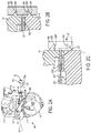
- FIG. 2C illustrates an alternate locking handle 50, where like numerals refer to like parts.
- a sleeve 50SS may be threadedly engaged or pressed into shaft 50S.
- a plunger 50P may be disposed and captured within sleeve 50SS.
- a spring 50B may be disposed between plunger 50P and shaft 50S biasing the plunger 50P outwardly towards protrusion 62P.
- plunger 50P does not escape sleeve 50SS as it is preferably captured therewithin.
- plunger 50P does not push protrusion 62P too far, which could damage switch 63.
- plunger 50P can move towards shaft 50S when the user continues to rotate knob 50K, even after protrusion 62P has bottomed out.
- sleeve 50SS retains knob 50K, so that it cannot be removed from top trunnion 43.
- FIGS. 4-5 Such mechanism is shown in FIGS. 4-5 , where a switch mechanism 60 is disposed in series with the handle switch 28S and motor 27. Preferably switch mechanism 60 acts as a normally-opened momentary switch.
- Switch mechanism 60 may be disposed in a cavity within trunnion body 41. However persons skilled in the art will recognize that switch mechanism 60 may be disposed in a cavity within top trunnion 43, or any other positions on chop saw 100 where the proximity of top trunnion 43 to trunnion body 41 can be detected.
- Switch mechanism 60 may have a cover 61 to substantially cover the different components of switch mechanism 60.
- switch mechanism 60 may have a switch 63, and a first lever 62 pivotally attached to trunnion body 41 about pivot 62A.
- a spring 62S may bias first level 62 away from switch 63.
- First level 62 may have a protrusion 62P that extends beyond cover 61. Protrusion 62P may be contacted by shaft 50S. As the user rotates knob 50K, shaft 50S moves further into switch mechanism 60, depressing protrusion 62P. Such movement causes first level 62 to rotate about pivot 62A. First level 62 may contact switch plunger 63P, closing the circuit of FIG. 4 , enabling use of chop saw 100.
- switch mechanism 60 is disposed on top trunnion 43, it may be preferable to threadingly engage shaft 50S unto trunnion body 41, to ensure that shaft 50S depresses protrusion 62P when top trunnion 43 is in the closed position of FIGS. 2A-2B .
- first lever 62 may be made of a soft material to provide compliance and bend when contacting plunger 63P, rather than exerting a full amount of force against plunger 63P.
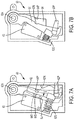
- FIGS. 7A-7C Such alternative switch mechanism 60 is shown in FIGS. 7A-7C , where like numerals refer to like parts.
- first lever 62 may be pivotally attached to trunnion body 41 about pivot 62A, and may have a protrusion 62P that extends beyond cover 61. Protrusion 62P may be contacted by shaft 50S. A spring 62S may bias first lever 62 away from switch 63.
- a second lever 64 may be disposed under first lever 62.
- a coil spring 65 may be disposed between first and second levers 62, 64 in order to bias first lever 62 towards second lever 64.
- a protrusion 64P on second lever 64 may engage a notch 62N in first lever 62 to prevent first lever 62 from over-rotating away from switch 63 beyond second lever 64.
- FIG. 7A shows the first and second levers 62, 64 in a neutral position (shown in solid lines) before shaft 50S contacts protrusion 62P.
- shaft 50S contacts protrusion 62P, it can rotate first and second levers 62, 64 along direction X towards switch 63, until second lever 64 depresses plunger 63P.
- second lever 64 moves along with first lever 62 due to the biasing force of spring 65.
- second lever 64 will continue moving towards switch 63 until the housing of switch 63 is contacted by a stop protrusion 64S on second lever 64. Such position is shown in broken lines in FIG. 7A . When such contact occurs, second lever 64 will not rotate any further along direction X. Persons skilled in the art will recognize limiting motion of second lever 64 will result in limiting the amount of force exerted on plunger 63P. First lever 62 however can continue moving along direction X without exerting any further force on plunger 63P, as first lever 62 can move beyond switch 63, as shown in FIG. 7B .
- switch mechanism 60 could be replaced with other types of electric sensors, such as Hall effects sensors, magnetic sensors, light sensors, proximity sensors, relays, etc. to detect the proximity or separation of top trunnion 43 relative to trunnion body 41. As with switch mechanism 60, such sensors would prevent the user from turning on chop saw 100 when the top trunnion 43 is in the opened position of FIG. 3 .
- FIGS. 8A-8D illustrate another mechanism to prevent the user from turning on or activating chop saw 100 when the top trunnion 43 is in the opened position of FIG. 3 .
- Handle 28 preferably has an on/off switch trigger 28S, which can be pivoted to contact a switch 28SS.
- handle 28 may carry a rocker 28R which is pivotably attached to handle 28.
- Rocker 28R may have a first arm 28RF connected to a spring 28RS, which in turn is attached to handle 28 to bias rocker 28R towards the position shown in FIG. 8A .
- Rocker 28R may have a second arm 28RA, which in turn is connected to a flexible wire or cable 45C.
- cable 45C may be connected to a plunger 45P.
- Plunger 45P preferably extends through top trunnion 43 and can contact trunnion body 41.
- a bottom washer 45BW may be attached to the plunger 45P.
- a spring 45S may be disposed between top trunnion 43 and bottom washer 45BW to bias plunger 45P towards trunnion body 41.
- a top washer 45TW may be also be attached to the plunger 45P to capture plunger 45P within top trunnion 43.
- plunger 45P will no longer contact trunnion body 41.
- Spring 45S will force plunger 45P away from top trunnion 43.
- Such movement will also pull cable 45C, causing rocker 28R to rotate into the position shown in FIG. 8C .
- first arm 28RF will contact on/off switch trigger 28S.
- Such contact will prevent the user from rotating on/off switch trigger 28S and thus preventing the user from turning on and operating chop saw 100.
Landscapes
- Life Sciences & Earth Sciences (AREA)
- Engineering & Computer Science (AREA)
- Mechanical Engineering (AREA)
- Wood Science & Technology (AREA)
- Forests & Forestry (AREA)
- Sawing (AREA)
Applications Claiming Priority (2)
| Application Number | Priority Date | Filing Date | Title |
|---|---|---|---|
| US201562137281P | 2015-03-24 | 2015-03-24 | |
| US15/053,339 US9993936B2 (en) | 2015-03-24 | 2016-02-25 | Chop saw with improved storage mode |
Publications (2)
| Publication Number | Publication Date |
|---|---|
| EP3072619A1 true EP3072619A1 (fr) | 2016-09-28 |
| EP3072619B1 EP3072619B1 (fr) | 2018-08-15 |
Family
ID=55456668
Family Applications (1)
| Application Number | Title | Priority Date | Filing Date |
|---|---|---|---|
| EP16158600.3A Active EP3072619B1 (fr) | 2015-03-24 | 2016-03-04 | Scie pivotante avec mode de stockage |
Country Status (3)
| Country | Link |
|---|---|
| US (1) | US9993936B2 (fr) |
| EP (1) | EP3072619B1 (fr) |
| CN (1) | CN205650896U (fr) |
Families Citing this family (7)
| Publication number | Priority date | Publication date | Assignee | Title |
|---|---|---|---|---|
| TWI593489B (zh) * | 2015-02-03 | 2017-08-01 | 力山工業股份有限公司 | 具有安全裝置的可折收鋸切機 |
| TWI656931B (zh) * | 2018-02-01 | 2019-04-21 | 力山工業股份有限公司 | 可收折鋸切機 |
| US11691208B2 (en) * | 2018-10-27 | 2023-07-04 | Ridge Tool Company | Pipe cut-off tool and accessories for such tools |
| TWI745198B (zh) * | 2020-12-21 | 2021-11-01 | 力山工業股份有限公司 | 具安全裝置的可收合鋸切機 |
| TWI745199B (zh) * | 2020-12-21 | 2021-11-01 | 力山工業股份有限公司 | 具安全裝置的可收合鋸切機 |
| TWI775628B (zh) * | 2021-09-30 | 2022-08-21 | 力山工業股份有限公司 | 具收折斷電功能的鋸切機 |
| CN115958244A (zh) * | 2021-10-09 | 2023-04-14 | 力山工业股份有限公司 | 具收折断电功能的锯切机 |
Citations (4)
| Publication number | Priority date | Publication date | Assignee | Title |
|---|---|---|---|---|
| EP1415744A2 (fr) * | 2002-11-01 | 2004-05-06 | Black & Decker Inc. | Scie de carreaux |
| US20070205665A1 (en) * | 2006-03-02 | 2007-09-06 | Yoshikazu Kawano | Power Tool with Power Supply Circuit Supplying Different Level DC Voltages to Different Auxiliary Devices |
| CN102886566A (zh) * | 2011-07-22 | 2013-01-23 | 苏州宝时得电动工具有限公司 | 切割机 |
| EP2774731A1 (fr) * | 2013-03-08 | 2014-09-10 | Black & Decker, Inc. | Scie à broyer avec mode de stockage amélioré |
Family Cites Families (3)
| Publication number | Priority date | Publication date | Assignee | Title |
|---|---|---|---|---|
| JPH0811327B2 (ja) * | 1990-11-16 | 1996-02-07 | 三星電子株式会社 | 卓上切断機の駆動安全装置 |
| US8220372B2 (en) * | 2009-04-28 | 2012-07-17 | Credo Technology Corporation | Combination table-miter saw safety system |
| TWI593489B (zh) * | 2015-02-03 | 2017-08-01 | 力山工業股份有限公司 | 具有安全裝置的可折收鋸切機 |
-
2016
- 2016-02-25 US US15/053,339 patent/US9993936B2/en active Active
- 2016-03-04 EP EP16158600.3A patent/EP3072619B1/fr active Active
- 2016-03-21 CN CN201620216320.5U patent/CN205650896U/zh not_active Expired - Fee Related
Patent Citations (4)
| Publication number | Priority date | Publication date | Assignee | Title |
|---|---|---|---|---|
| EP1415744A2 (fr) * | 2002-11-01 | 2004-05-06 | Black & Decker Inc. | Scie de carreaux |
| US20070205665A1 (en) * | 2006-03-02 | 2007-09-06 | Yoshikazu Kawano | Power Tool with Power Supply Circuit Supplying Different Level DC Voltages to Different Auxiliary Devices |
| CN102886566A (zh) * | 2011-07-22 | 2013-01-23 | 苏州宝时得电动工具有限公司 | 切割机 |
| EP2774731A1 (fr) * | 2013-03-08 | 2014-09-10 | Black & Decker, Inc. | Scie à broyer avec mode de stockage amélioré |
Also Published As
| Publication number | Publication date |
|---|---|
| US9993936B2 (en) | 2018-06-12 |
| EP3072619B1 (fr) | 2018-08-15 |
| CN205650896U (zh) | 2016-10-19 |
| US20160279822A1 (en) | 2016-09-29 |
Similar Documents
| Publication | Publication Date | Title |
|---|---|---|
| EP3072619B1 (fr) | Scie pivotante avec mode de stockage | |
| US20080172891A1 (en) | Hand-held circular saw | |
| EP0633105A1 (fr) | Scie pivotante à levier sous forme de parallélogramme | |
| US6758122B2 (en) | Guard and control assembly for a compound miter saw | |
| US5184534A (en) | Operation safety device for a portable power tool | |
| EP1712318A2 (fr) | Scie pivotante | |
| JP2006055996A (ja) | 鋸 | |
| CN102114555A (zh) | 电动工具 | |
| EP3141356B1 (fr) | Ciseaux électriques | |
| CN103282808A (zh) | 光纤切割器及光纤切割器单元 | |
| JP5384886B2 (ja) | スライドマルノコ | |
| EP2436494B1 (fr) | Découpeuse avec un ensemble de protection | |
| FR2465456A1 (fr) | Appareil electromenager de traitement des aliments | |
| EP2500125A1 (fr) | Collecteur de poussière pour une machine de découpe | |
| CN1315612C (zh) | 电动加工机 | |
| JP2017213655A (ja) | 卓上切断機 | |
| US9533361B2 (en) | Cutting machines | |
| US8955446B1 (en) | Thread cutting mechanism for sewing machine | |
| US10293514B2 (en) | Cam actuated guard for a saw | |
| EP2253439B1 (fr) | Scie à onglets | |
| JP4847098B2 (ja) | 切断機 | |
| EP1621276B1 (fr) | Agencement d'une scie à onglet avec une capacité de coupe augmentée | |
| WO2015098615A1 (fr) | Outil de coupe de table | |
| JP2016087732A (ja) | 卓上切断機 | |
| EP1800782B1 (fr) | Scie pivotante avec capot protecteur inférieur rotatif |
Legal Events
| Date | Code | Title | Description |
|---|---|---|---|
| PUAI | Public reference made under article 153(3) epc to a published international application that has entered the european phase |
Free format text: ORIGINAL CODE: 0009012 |
|
| AK | Designated contracting states |
Kind code of ref document: A1 Designated state(s): AL AT BE BG CH CY CZ DE DK EE ES FI FR GB GR HR HU IE IS IT LI LT LU LV MC MK MT NL NO PL PT RO RS SE SI SK SM TR |
|
| AX | Request for extension of the european patent |
Extension state: BA ME |
|
| 17P | Request for examination filed |
Effective date: 20161014 |
|
| RBV | Designated contracting states (corrected) |
Designated state(s): AL AT BE BG CH CY CZ DE DK EE ES FI FR GB GR HR HU IE IS IT LI LT LU LV MC MK MT NL NO PL PT RO RS SE SI SK SM TR |
|
| STAA | Information on the status of an ep patent application or granted ep patent |
Free format text: STATUS: REQUEST FOR EXAMINATION WAS MADE |
|
| GRAP | Despatch of communication of intention to grant a patent |
Free format text: ORIGINAL CODE: EPIDOSNIGR1 |
|
| STAA | Information on the status of an ep patent application or granted ep patent |
Free format text: STATUS: GRANT OF PATENT IS INTENDED |
|
| INTG | Intention to grant announced |
Effective date: 20180301 |
|
| GRAS | Grant fee paid |
Free format text: ORIGINAL CODE: EPIDOSNIGR3 |
|
| GRAA | (expected) grant |
Free format text: ORIGINAL CODE: 0009210 |
|
| STAA | Information on the status of an ep patent application or granted ep patent |
Free format text: STATUS: THE PATENT HAS BEEN GRANTED |
|
| AK | Designated contracting states |
Kind code of ref document: B1 Designated state(s): AL AT BE BG CH CY CZ DE DK EE ES FI FR GB GR HR HU IE IS IT LI LT LU LV MC MK MT NL NO PL PT RO RS SE SI SK SM TR |
|
| REG | Reference to a national code |
Ref country code: CH Ref legal event code: EP Ref country code: GB Ref legal event code: FG4D Ref country code: AT Ref legal event code: REF Ref document number: 1029185 Country of ref document: AT Kind code of ref document: T Effective date: 20180815 |
|
| REG | Reference to a national code |
Ref country code: IE Ref legal event code: FG4D |
|
| REG | Reference to a national code |
Ref country code: DE Ref legal event code: R096 Ref document number: 602016004655 Country of ref document: DE |
|
| REG | Reference to a national code |
Ref country code: SE Ref legal event code: TRGR |
|
| REG | Reference to a national code |
Ref country code: NL Ref legal event code: MP Effective date: 20180815 |
|
| REG | Reference to a national code |
Ref country code: LT Ref legal event code: MG4D |
|
| REG | Reference to a national code |
Ref country code: AT Ref legal event code: MK05 Ref document number: 1029185 Country of ref document: AT Kind code of ref document: T Effective date: 20180815 |
|
| PG25 | Lapsed in a contracting state [announced via postgrant information from national office to epo] |
Ref country code: LT Free format text: LAPSE BECAUSE OF FAILURE TO SUBMIT A TRANSLATION OF THE DESCRIPTION OR TO PAY THE FEE WITHIN THE PRESCRIBED TIME-LIMIT Effective date: 20180815 Ref country code: RS Free format text: LAPSE BECAUSE OF FAILURE TO SUBMIT A TRANSLATION OF THE DESCRIPTION OR TO PAY THE FEE WITHIN THE PRESCRIBED TIME-LIMIT Effective date: 20180815 Ref country code: NL Free format text: LAPSE BECAUSE OF FAILURE TO SUBMIT A TRANSLATION OF THE DESCRIPTION OR TO PAY THE FEE WITHIN THE PRESCRIBED TIME-LIMIT Effective date: 20180815 Ref country code: FI Free format text: LAPSE BECAUSE OF FAILURE TO SUBMIT A TRANSLATION OF THE DESCRIPTION OR TO PAY THE FEE WITHIN THE PRESCRIBED TIME-LIMIT Effective date: 20180815 Ref country code: NO Free format text: LAPSE BECAUSE OF FAILURE TO SUBMIT A TRANSLATION OF THE DESCRIPTION OR TO PAY THE FEE WITHIN THE PRESCRIBED TIME-LIMIT Effective date: 20181115 Ref country code: GR Free format text: LAPSE BECAUSE OF FAILURE TO SUBMIT A TRANSLATION OF THE DESCRIPTION OR TO PAY THE FEE WITHIN THE PRESCRIBED TIME-LIMIT Effective date: 20181116 Ref country code: BG Free format text: LAPSE BECAUSE OF FAILURE TO SUBMIT A TRANSLATION OF THE DESCRIPTION OR TO PAY THE FEE WITHIN THE PRESCRIBED TIME-LIMIT Effective date: 20181115 Ref country code: IS Free format text: LAPSE BECAUSE OF FAILURE TO SUBMIT A TRANSLATION OF THE DESCRIPTION OR TO PAY THE FEE WITHIN THE PRESCRIBED TIME-LIMIT Effective date: 20181215 Ref country code: AT Free format text: LAPSE BECAUSE OF FAILURE TO SUBMIT A TRANSLATION OF THE DESCRIPTION OR TO PAY THE FEE WITHIN THE PRESCRIBED TIME-LIMIT Effective date: 20180815 |
|
| PG25 | Lapsed in a contracting state [announced via postgrant information from national office to epo] |
Ref country code: HR Free format text: LAPSE BECAUSE OF FAILURE TO SUBMIT A TRANSLATION OF THE DESCRIPTION OR TO PAY THE FEE WITHIN THE PRESCRIBED TIME-LIMIT Effective date: 20180815 Ref country code: LV Free format text: LAPSE BECAUSE OF FAILURE TO SUBMIT A TRANSLATION OF THE DESCRIPTION OR TO PAY THE FEE WITHIN THE PRESCRIBED TIME-LIMIT Effective date: 20180815 Ref country code: AL Free format text: LAPSE BECAUSE OF FAILURE TO SUBMIT A TRANSLATION OF THE DESCRIPTION OR TO PAY THE FEE WITHIN THE PRESCRIBED TIME-LIMIT Effective date: 20180815 |
|
| PG25 | Lapsed in a contracting state [announced via postgrant information from national office to epo] |
Ref country code: CZ Free format text: LAPSE BECAUSE OF FAILURE TO SUBMIT A TRANSLATION OF THE DESCRIPTION OR TO PAY THE FEE WITHIN THE PRESCRIBED TIME-LIMIT Effective date: 20180815 Ref country code: RO Free format text: LAPSE BECAUSE OF FAILURE TO SUBMIT A TRANSLATION OF THE DESCRIPTION OR TO PAY THE FEE WITHIN THE PRESCRIBED TIME-LIMIT Effective date: 20180815 Ref country code: PL Free format text: LAPSE BECAUSE OF FAILURE TO SUBMIT A TRANSLATION OF THE DESCRIPTION OR TO PAY THE FEE WITHIN THE PRESCRIBED TIME-LIMIT Effective date: 20180815 Ref country code: ES Free format text: LAPSE BECAUSE OF FAILURE TO SUBMIT A TRANSLATION OF THE DESCRIPTION OR TO PAY THE FEE WITHIN THE PRESCRIBED TIME-LIMIT Effective date: 20180815 Ref country code: EE Free format text: LAPSE BECAUSE OF FAILURE TO SUBMIT A TRANSLATION OF THE DESCRIPTION OR TO PAY THE FEE WITHIN THE PRESCRIBED TIME-LIMIT Effective date: 20180815 |
|
| PGFP | Annual fee paid to national office [announced via postgrant information from national office to epo] |
Ref country code: TR Payment date: 20190121 Year of fee payment: 15 |
|
| REG | Reference to a national code |
Ref country code: DE Ref legal event code: R097 Ref document number: 602016004655 Country of ref document: DE |
|
| PG25 | Lapsed in a contracting state [announced via postgrant information from national office to epo] |
Ref country code: DK Free format text: LAPSE BECAUSE OF FAILURE TO SUBMIT A TRANSLATION OF THE DESCRIPTION OR TO PAY THE FEE WITHIN THE PRESCRIBED TIME-LIMIT Effective date: 20180815 Ref country code: SM Free format text: LAPSE BECAUSE OF FAILURE TO SUBMIT A TRANSLATION OF THE DESCRIPTION OR TO PAY THE FEE WITHIN THE PRESCRIBED TIME-LIMIT Effective date: 20180815 Ref country code: SK Free format text: LAPSE BECAUSE OF FAILURE TO SUBMIT A TRANSLATION OF THE DESCRIPTION OR TO PAY THE FEE WITHIN THE PRESCRIBED TIME-LIMIT Effective date: 20180815 |
|
| PGFP | Annual fee paid to national office [announced via postgrant information from national office to epo] |
Ref country code: SE Payment date: 20190311 Year of fee payment: 4 |
|
| PLBE | No opposition filed within time limit |
Free format text: ORIGINAL CODE: 0009261 |
|
| STAA | Information on the status of an ep patent application or granted ep patent |
Free format text: STATUS: NO OPPOSITION FILED WITHIN TIME LIMIT |
|
| 26N | No opposition filed |
Effective date: 20190516 |
|
| PG25 | Lapsed in a contracting state [announced via postgrant information from national office to epo] |
Ref country code: SI Free format text: LAPSE BECAUSE OF FAILURE TO SUBMIT A TRANSLATION OF THE DESCRIPTION OR TO PAY THE FEE WITHIN THE PRESCRIBED TIME-LIMIT Effective date: 20180815 |
|
| PG25 | Lapsed in a contracting state [announced via postgrant information from national office to epo] |
Ref country code: MC Free format text: LAPSE BECAUSE OF FAILURE TO SUBMIT A TRANSLATION OF THE DESCRIPTION OR TO PAY THE FEE WITHIN THE PRESCRIBED TIME-LIMIT Effective date: 20180815 |
|
| REG | Reference to a national code |
Ref country code: CH Ref legal event code: PL |
|
| PG25 | Lapsed in a contracting state [announced via postgrant information from national office to epo] |
Ref country code: LU Free format text: LAPSE BECAUSE OF NON-PAYMENT OF DUE FEES Effective date: 20190304 |
|
| REG | Reference to a national code |
Ref country code: BE Ref legal event code: MM Effective date: 20190331 |
|
| PG25 | Lapsed in a contracting state [announced via postgrant information from national office to epo] |
Ref country code: LI Free format text: LAPSE BECAUSE OF NON-PAYMENT OF DUE FEES Effective date: 20190331 Ref country code: CH Free format text: LAPSE BECAUSE OF NON-PAYMENT OF DUE FEES Effective date: 20190331 Ref country code: IE Free format text: LAPSE BECAUSE OF NON-PAYMENT OF DUE FEES Effective date: 20190304 |
|
| PG25 | Lapsed in a contracting state [announced via postgrant information from national office to epo] |
Ref country code: BE Free format text: LAPSE BECAUSE OF NON-PAYMENT OF DUE FEES Effective date: 20190331 Ref country code: FR Free format text: LAPSE BECAUSE OF NON-PAYMENT OF DUE FEES Effective date: 20190331 |
|
| PG25 | Lapsed in a contracting state [announced via postgrant information from national office to epo] |
Ref country code: TR Free format text: LAPSE BECAUSE OF FAILURE TO SUBMIT A TRANSLATION OF THE DESCRIPTION OR TO PAY THE FEE WITHIN THE PRESCRIBED TIME-LIMIT Effective date: 20180815 |
|
| PG25 | Lapsed in a contracting state [announced via postgrant information from national office to epo] |
Ref country code: PT Free format text: LAPSE BECAUSE OF FAILURE TO SUBMIT A TRANSLATION OF THE DESCRIPTION OR TO PAY THE FEE WITHIN THE PRESCRIBED TIME-LIMIT Effective date: 20181215 Ref country code: MT Free format text: LAPSE BECAUSE OF NON-PAYMENT OF DUE FEES Effective date: 20190304 |
|
| PG25 | Lapsed in a contracting state [announced via postgrant information from national office to epo] |
Ref country code: SE Free format text: LAPSE BECAUSE OF NON-PAYMENT OF DUE FEES Effective date: 20200305 |
|
| PG25 | Lapsed in a contracting state [announced via postgrant information from national office to epo] |
Ref country code: CY Free format text: LAPSE BECAUSE OF FAILURE TO SUBMIT A TRANSLATION OF THE DESCRIPTION OR TO PAY THE FEE WITHIN THE PRESCRIBED TIME-LIMIT Effective date: 20180815 |
|
| PG25 | Lapsed in a contracting state [announced via postgrant information from national office to epo] |
Ref country code: HU Free format text: LAPSE BECAUSE OF FAILURE TO SUBMIT A TRANSLATION OF THE DESCRIPTION OR TO PAY THE FEE WITHIN THE PRESCRIBED TIME-LIMIT; INVALID AB INITIO Effective date: 20160304 |
|
| PG25 | Lapsed in a contracting state [announced via postgrant information from national office to epo] |
Ref country code: IT Free format text: LAPSE BECAUSE OF NON-PAYMENT OF DUE FEES Effective date: 20200304 |
|
| PG25 | Lapsed in a contracting state [announced via postgrant information from national office to epo] |
Ref country code: MK Free format text: LAPSE BECAUSE OF FAILURE TO SUBMIT A TRANSLATION OF THE DESCRIPTION OR TO PAY THE FEE WITHIN THE PRESCRIBED TIME-LIMIT Effective date: 20180815 |
|
| PGFP | Annual fee paid to national office [announced via postgrant information from national office to epo] |
Ref country code: GB Payment date: 20260324 Year of fee payment: 11 |
|
| PGFP | Annual fee paid to national office [announced via postgrant information from national office to epo] |
Ref country code: DE Payment date: 20260320 Year of fee payment: 11 |