EP3072641B1 - Ferngesteuertes roboterfahrzeug - Google Patents
Ferngesteuertes roboterfahrzeug Download PDFInfo
- Publication number
- EP3072641B1 EP3072641B1 EP14864490.9A EP14864490A EP3072641B1 EP 3072641 B1 EP3072641 B1 EP 3072641B1 EP 14864490 A EP14864490 A EP 14864490A EP 3072641 B1 EP3072641 B1 EP 3072641B1
- Authority
- EP
- European Patent Office
- Prior art keywords
- robotic vehicle
- remote
- articulated arm
- controlled
- clamp
- Prior art date
- Legal status (The legal status is an assumption and is not a legal conclusion. Google has not performed a legal analysis and makes no representation as to the accuracy of the status listed.)
- Active
Links
Images



Classifications
-
- B—PERFORMING OPERATIONS; TRANSPORTING
- B25—HAND TOOLS; PORTABLE POWER-DRIVEN TOOLS; MANIPULATORS
- B25J—MANIPULATORS; CHAMBERS PROVIDED WITH MANIPULATION DEVICES
- B25J11/00—Manipulators not otherwise provided for
- B25J11/002—Manipulators for defensive or military tasks
- B25J11/0025—Manipulators for defensive or military tasks handling explosives, bombs or hazardous objects
-
- B—PERFORMING OPERATIONS; TRANSPORTING
- B25—HAND TOOLS; PORTABLE POWER-DRIVEN TOOLS; MANIPULATORS
- B25J—MANIPULATORS; CHAMBERS PROVIDED WITH MANIPULATION DEVICES
- B25J13/00—Controls for manipulators
- B25J13/06—Control stands, e.g. consoles, switchboards
-
- B—PERFORMING OPERATIONS; TRANSPORTING
- B25—HAND TOOLS; PORTABLE POWER-DRIVEN TOOLS; MANIPULATORS
- B25J—MANIPULATORS; CHAMBERS PROVIDED WITH MANIPULATION DEVICES
- B25J15/00—Gripping heads and other end effectors
- B25J15/02—Gripping heads and other end effectors servo-actuated
- B25J15/0253—Gripping heads and other end effectors servo-actuated comprising parallel grippers
-
- B—PERFORMING OPERATIONS; TRANSPORTING
- B25—HAND TOOLS; PORTABLE POWER-DRIVEN TOOLS; MANIPULATORS
- B25J—MANIPULATORS; CHAMBERS PROVIDED WITH MANIPULATION DEVICES
- B25J5/00—Manipulators mounted on wheels or on carriages
- B25J5/005—Manipulators mounted on wheels or on carriages mounted on endless tracks or belts
-
- B—PERFORMING OPERATIONS; TRANSPORTING
- B25—HAND TOOLS; PORTABLE POWER-DRIVEN TOOLS; MANIPULATORS
- B25J—MANIPULATORS; CHAMBERS PROVIDED WITH MANIPULATION DEVICES
- B25J5/00—Manipulators mounted on wheels or on carriages
- B25J5/007—Manipulators mounted on wheels or on carriages mounted on wheels
-
- B—PERFORMING OPERATIONS; TRANSPORTING
- B62—LAND VEHICLES FOR TRAVELLING OTHERWISE THAN ON RAILS
- B62D—MOTOR VEHICLES; TRAILERS
- B62D55/00—Endless track vehicles
- B62D55/02—Endless track vehicles with tracks and additional ground wheels
-
- F—MECHANICAL ENGINEERING; LIGHTING; HEATING; WEAPONS; BLASTING
- F41—WEAPONS
- F41H—ARMOUR; ARMOURED TURRETS; ARMOURED OR ARMED VEHICLES; MEANS OF ATTACK OR DEFENCE, e.g. CAMOUFLAGE, IN GENERAL
- F41H11/00—Defence installations; Defence devices
- F41H11/12—Means for clearing land minefields; Systems specially adapted for detection of landmines
- F41H11/16—Self-propelled mine-clearing vehicles; Mine-clearing devices attachable to vehicles
-
- G—PHYSICS
- G05—CONTROLLING; REGULATING
- G05D—SYSTEMS FOR CONTROLLING OR REGULATING NON-ELECTRIC VARIABLES
- G05D1/00—Control of position, course, altitude or attitude of land, water, air or space vehicles, e.g. using automatic pilots
- G05D1/0011—Control of position, course, altitude or attitude of land, water, air or space vehicles, e.g. using automatic pilots associated with a remote control arrangement
-
- G—PHYSICS
- G05—CONTROLLING; REGULATING
- G05D—SYSTEMS FOR CONTROLLING OR REGULATING NON-ELECTRIC VARIABLES
- G05D1/00—Control of position, course, altitude or attitude of land, water, air or space vehicles, e.g. using automatic pilots
- G05D1/02—Control of position or course in two dimensions
- G05D1/021—Control of position or course in two dimensions specially adapted to land vehicles
- G05D1/0231—Control of position or course in two dimensions specially adapted to land vehicles using optical position detecting means
Definitions
- the present invention as expressed in the heading of the present specification, relates to a remote-controlled robotic vehicle which is of the type of robotic vehicles whose main purpose is the detection, recognition and deactivation of explosive devices or that are dangerous to society.
- the remote-controlled robotic vehicle object of the invention combines a movement system based on two lateral trains of wheels and two caterpillar tracks with the purpose of facilitating the movement thereof along smooth ground and along any other kind of irregular or slippery ground.
- the remote-controlled robotic vehicle object of the invention is provided with a pair of articulated arms, one of the arms can hold an object and the other arm can examine it.
- the present specification describes a remote-controlled robotic vehicle, which has an average size capable of handling objects of up to 200 kilograms in weight, and is especially applicable to police, military and even civil intervention missions in missions involving a certain degree of risk.
- the remote-controlled robotic vehicle is applicable in the face of actions intended to attack society structures, such as the placement or alleged placement of explosive devices, "dirty" bombs, attacks with chemical gases, biological material or the dispersal of radioactive elements.
- the remote-controlled robotic vehicle can undertake independent surveillance missions in perimeters, borders, industries or places where independent surveillance can be of use.
- this type of robot has a series of control elements, such as viewing cameras and proximity sensors.
- document ES 2 241 490 describes a " self-propelled robot for the handling of explosive charges " , which comprises means of movement defined by two width-adjustable lateral caterpillar tracks and which incorporate an articulated arm, in four segments, which terminates in a clamp, with the first segment in the form of a fork actuated by a pair of cylinders, and in the folding thereof the clamp body passes between the pair of prongs of the first segment.
- document ES 1 073 757 describes a " remote-controlled robot for special operations ", being of the type of robots used to carry out risky operations and having a running gear, a telescopic arm which terminates in a clamp and remote control and operation means, such that the robot incorporates a 360° rotating turret on the running gear provided with at least one thermal camera, and to which turret an arm constituted by a series of six segments is attached, which are pivotally joined to each other and actuated by hydraulic cylinders, the arm having at least one camera and at least one deterrent weapon.
- each joint of the arm is directly controlled by the operator, which implies that, in order for the clamp to approach an object with the desired position and angle, the operator must act independently and successively with respect to each articulated movement until the desired position is finally achieved, which requires skill and time in the operation.
- Document CN 202045634 U discloses a remote-controlled robotic vehicle for handling explosives having two articulated arms.
- Document EP 1 502 843 A2 discloses a robotic vehicle for handling explosives having two wheel sets and two caterpillar sets inside the wheel sets and slightly above the wheel sets.
- document US 6113343 A presents an explosives disposal robot, which presents a base structure for a manipulator arm constituted by a first arm 226 (constituted by a pair of beam members 230) and a second arm 228 (likewise constituted by a pair of beam members, that is to say, they are actually pairs of arms), each of which is actuated independently with respect to the corresponding rotation axis.
- Document JP 200032875 describes a link chain device to move a working vehicle, which vehicle can vary its own width, for which each one of the running gears incorporates a pair of elements such that said pairs, attached to both running gears, fit into respective tubular elements that are integral to the structure of the vehicle itself.
- document DE 2409027 describes a leveling blade, such that the width of the leveling blade can be adjusted with the purpose of travelling by road, being adjustable by means of respective sliding ends.
- the present specification describes a remote-controlled robotic vehicle as defined in the appended claim 1 of the type of robotic vehicles provided with running means and an articulated arm which terminates in a clamp, which is remotely controlled to carry out different risky operations, wherein
- each set of lateral drive wheels is actuated by an electric motor, having traction in a differential manner and providing direction and rotation.
- the first articulated arm in a practical embodiment, is defined by three segments and a first clamp, the third segment being provided with ⁇ 90° lateral rotation and the first clamp being provided with endless rotation.
- the weight handling capacity of the first articulated arm varies depending on the articulation positions thereof, such that the more it extends, the lower the capacity.
- the second articulated arm is defined by three segments and a second clamp, the third segment being provided with 360° rotation with respect to the longitudinal axis and an elevation/descent rotation with respect to a transversal axis, while the second clamp is provided with endless rotation.
- the first clamp of the first hydraulic articulated arm is provided with a pressure sensor associated with the supply of flow and pressure, being able to regulate and know the precise force exerted on the object to be handled.
- the force or pressure exerted by the second clamp of the second articulated arm is controlled by the control of the electric current of the motor actuating the same.
- the control means of the robotic vehicle have a spatial calculation system, and whenever the control operator of the robotic vehicle selects the position of the corresponding clamp with respect to the object to be handled, the articulated arm will carry out the precise and simultaneous movements of its different segments to position itself optimally for the handling of the object, carrying out said movements in a fast and precise manner.
- the first clamp of the first articulated arm is provided at its ends with mechanical joints having a short range which, associated to inner springs thereof, shall be the ones to withstand the pressure exerted on the object to be handled.
- the inner springs of the first clamp of the first articulated arm are associated with electronic distance sensors.
- the robotic vehicle incorporates inertial sensors based on accelerometers associated with the drive shaft of the wheel set, having its global positioning and being able to move independently according to the routes set by the operator in the control equipment, and also incorporating obstacle sensors allowing it to avoid obstacles during the route and to return to the set route.
- control equipment incorporates means to connect to Internet in order to be controlled from anywhere and to connect to mobile devices from which it can be controlled.
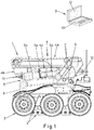
- the robotic vehicle 1 is provided with two wheel sets 2, one at each side, comprised by three wheels each, each wheel set 2 being actuated by the corresponding motor, and two caterpillar track sets 3, one at each side inside the wheel sets 2, the caterpillar track sets 3 being disposed slightly above the wheel sets 2, as shown in figures 1 and 2 of the drawings, such that both sets move together and the main contact with the ground corresponds to the wheel set 2, given that the two caterpillar track sets 3 remain in a slightly elevated position.
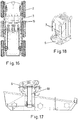
- the robotic vehicle is directed through the use of the electric motors 19, which act independently on the wheel sets 2, such that it enables traction in a differential manner, providing direction and even rotation around its own axis or around the central vertical axis, as shown in figure 16 of the drawings.
- the movement controls are carried out by means of closed loop systems in the form of digital servomechanisms.
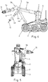
- the robotic vehicle 1 incorporates a first hydraulic articulated arm 1 mounted on a 360° rotating turret 6 through universal joint means 7, enabling movement thereof with respect to the longitudinal axis of the aforementioned first articulated arm 4, and a second electric articulated arm 5 that rotates with respect to a vertical mounting axis 8.
- figure 17 of the drawings shows the rotation axis 18 of the turret 6 to enable 360° rotation thereof
- figure 18 of the drawings shows the double joint 7 through which the first articulated arm 4 is mounted in the turret 6.
- the robotic vehicle 1 is associated with control equipment integrated in a box 9 that comprises a display screen 12 of images sent by cameras mounted on the robotic vehicle 1, a touch screen 13 in horizontal interface position with the operator, and an HMI interface device defined by a games controller "gamepad”.
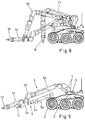
- the first articulated arm 4 is defined by three segments, 4a, 4b and 4c, the third segment 4c being provided with ⁇ 90° lateral rotation and the first clamp 10 being provided with endless rotation, such that the weight handling capacity of this first articulated arm 4 varies depending on the articulation positions, such that the more it extends, the lower the capacity.
- the second articulated arm 5 is defined by three segments 5a, 5b and 5c, the third segment 5c being provided with 360° rotation with respect to the longitudinal axis and the second clamp 11 being provided with endless rotation.
- the second articulated arm 5 will have the following movements:
- Figure 9 of the drawings clearly shows the different segments making up the first and the second articulated arms, as well as the double joint 7 through which the first articulated arm 4 is joined to the turret 6.
- the first clamp 10 of the first hydraulic articulated arm 4 is provided with a pressure sensor associated with the supply of flow and pressure, being able to regulate and know the precise force exerted on the object to be handled.
- the force or pressure exerted by the second clamp 11 of the second articulated arm 5 is controlled by the control of the electric current of the motor actuating the same.
- the control means of the robotic vehicle 1 have a spatial calculation system, and whenever the control operator of the robotic vehicle 1 selects the position of the corresponding clamp with respect to the object to be handled, the articulated arm will carry out the precise and simultaneous movements of its different segments to position itself optimally for the handling of the object.
- first clamp 10 of the first articulated arm 4 incorporates means to control the force exerted therein, which makes it possible to control forces from a few grams to up to a few kilograms, especially for the handling of very delicate objects.
- the first clamp 10 is provided with mechanical joints 14 having a short range, at the ends 15 of the jaws constituting the same, such that the joint makes it possible to place inner springs 16 in the structure of the first clamp 10 itself in order for the first pressure exerted to be transmitted to the inner springs 15, thereby maintaining, by definition, the pressure on the object being held.
- this first clamp 10 can keep compressing the object outside of the range of detection of the force provided by this design, reaching ranges of force of the order of tons.
- the hydraulic pressure sensor is the one providing the information of the exerted force.
- Said design therefore makes it possible to know and control, with the same clamp and with excellent precision, forces from a few grams to a few tons.
- the robotic vehicle 1 incorporates inertial sensors based on accelerometers associated with the drive shaft of the wheel set, having its global positioning and being able to move autonomously according to the routes set by the operator in the control equipment.
- the electronic control system of the robotic vehicle 1, integrated in the transportable box 9, consists of a high-capacity management unit with embedded computer architecture and local control plates to command the elements.
- Energy source is provided by an electric energy storage group formed by lithium-ion batteries, capable of providing energy for typical missions of up to 4 hours.
- the robotic vehicle 1 is remote controlled by means of the control equipment that takes the form of the box 9, which consists of the following:
- Data transmission between the control box 9 and the robotic vehicle 1 is carried out by means of a digital radio link, with highly secure modulation and encryption; alternatively, it can also be connected by means of an optical fiber cable line as required by the conditions or the operator.
- control center based on the box 9, is fully transportable and has its own supply of energy by means of the use of the latest lithium batteries.
- the robotic vehicle 1 can have up to ten video cameras to see the surroundings, which can be optical and fixed-position cameras or have total control with respect to movements and zoom, infrared lighting, infrared vision and thermographic cameras.
- it can have laser and ultrasound obstacle sensors.
- the robotic vehicle 1 has global positioning technology (GPS or similar) and inertial sensors (accelerometers in its shafts) such that it can know its position with precision as well as its variations relative to the same, even without the coverage of the global position satellite systems.
- GPS global positioning technology
- inertial sensors accelerometers in its shafts
- the interface of the operator makes it possible to design routes set out on a map, such that the vehicle, by means of the systems described above, can move independently towards the desired site or travel during continuous surveillance missions.
- Obstacle sensors combined with image recognition, allow the robot, in the presence of obstacles, to have intelligence to overcome them and trace slight variations to the programmed route.
- the control of the robotic vehicle 1, formed by the box 9 with the display and control elements thereof, has the capacity to connect to the worldwide web, such that the ongoing mission can be seen or the entire system can be controlled from anywhere in the world. This way, it is highly useful in training or even in decision-making processes in sensitive missions, where said decisions can be made anywhere in the world.
- said connectivity also enables a diagnostic of the status of the robotic vehicle such that it can be used as a technical intervention.
- the robotic vehicle has connectivity systems to connect to new technologies such that, by means of the correct interface and applications especially designed for said purpose, the robotic vehicle can be controlled by means of the latest mobile devices, so that multiple operator interfaces can coexist by giving up or assuming the command thereof.
- the operator-robotic vehicle communication method by means of "quick start", allows the vehicle to be controlled through the gamepad without the use or startup of the control center arranged in the box.
- This function is only valid for short distances and allows the robotic vehicle to be deployed from its transportation to its preparation for the mission, while the equipment deploys its contingent or starts up the main control system, being especially useful to reduce times of action in critical situations.
Landscapes
- Engineering & Computer Science (AREA)
- Mechanical Engineering (AREA)
- Robotics (AREA)
- Physics & Mathematics (AREA)
- Automation & Control Theory (AREA)
- General Physics & Mathematics (AREA)
- Remote Sensing (AREA)
- Radar, Positioning & Navigation (AREA)
- Aviation & Aerospace Engineering (AREA)
- Chemical & Material Sciences (AREA)
- Combustion & Propulsion (AREA)
- Transportation (AREA)
- Electromagnetism (AREA)
- General Engineering & Computer Science (AREA)
- Manipulator (AREA)
Claims (15)
- Ferngesteuertes Roboterfahrzeug von der Art von Roboterfahrzeugen, die mit einer Laufeinrichtung und einem gelenkigen Arm versehen sind, der in einer Halteeinrichtung mündet, und das ferngesteuert ist, um unterschiedliche gefährliche Vorgänge mittels einer Steuerungsanlageauszuführen, wobei
das Roboterfahrzeug (1) umfasst:zwei Radgruppen (2), eine auf jeder Seite, mit jeweils drei Rädern, wobei jede Radgruppe (2) durch entsprechende Motoren (19) angetrieben ist;zwei Raupenfahrwerksgruppen (3), eine auf jeder Seite an den Radgruppen (2), die geringfügig über den Radgruppen (2) angeordnet sind;einen ersten hydraulischen gelenkigen Arm (4), der durch eine Doppelgelenkseinrichtung (7) auf einem um 360° um die zentrale Achse (18) drehbaren Turm (6) montiert ist, wobei der erste hydraulische gelenkigen Arm (4) durch drei Segmente (4a, 4b und 4c) gebildet ist, wobei das dritte Segment (4c) mit einer seitlichen ± 90° Drehfähigkeit versehen ist und eine erste Halteeinrichtung (10) mit Endlosdrehung vorgesehen ist;einen zweiten elektrischen gelenkigen Arm (5), der in Bezug auf eine vertikale Montageachse (8) drehbar ist, undwobei das Roboterfahrzeug (1) ferngesteuert ist durch:
eine Steuerungsanlage, die in einem Gehäuse (9) integriert ist, und die aufweist:einen Anzeigebildschirm (12) für Bilder, die von Kameras gesendet werden, die an dem Roboterfahrzeug montiert sind;einen Berührbildschirm (13) an einer horizontalen Schnittstellenposition in Bezug auf den Bediener, undeine HMI-Schnittstelleneinrichtung, die durch ein Gamepad gebildet ist;derart, dass das Fahrzeug mit den beiden Radgruppen (2) und den beiden Raupenfahrwerksgruppen (3) über alle Arten von Untergrund bewegbar ist und mit den kombinierten Bewegungen der beiden gelenkigen Arme (4) und (5) es die Objekte hält und handhabt, die entsprechend den Befehlen zu untersuchen sind, die von dem Bediener durch die Steuerungsanlage auf der Grundlage des transportable Gehäuses (9) gegeben werden. - Ferngesteuertes Roboterfahrzeug nach Anspruch 1, dadurch gekennzeichnet, dass jede seitliche Antriebsradgruppe (2) durch einen Elektromotor angetrieben ist, der Traktion in differentieller Weise und Richtung und Drehung bietet.
- Ferngesteuertes Roboterfahrzeug nach Anspruch 1, dadurch gekennzeichnet, dass die beiden Radgruppen (2) und die beiden Raupenfahrwerksgruppen (3) gleichzeitig bewegbar sind.
- Ferngesteuertes Roboterfahrzeug nach Anspruch 1, dadurch gekennzeichnet, dass die Fähigkeit zur Handhabung eines Gewichts des ersten gelenkigen Arms (4) in Abhängigkeit von den Gelenksstellungen variierbar ist.
- Ferngesteuertes Roboterfahrzeug nach Anspruch 1, dadurch gekennzeichnet, dass der zweite gelenkige Arm (5) durch drei Segmente (5a, 5b und 5c) gebildet ist, wobei das dritte Segment (5c) mit einer 360°-Drehfähigkeit in Bezug auf die Längsachse und mit einer zweiten Halteeinrichtung (11) mit Endlosdrehung versehen ist.
- Ferngesteuertes Roboterfahrzeug nach Anspruch 1, dadurch gekennzeichnet, dass die erste Halteeinrichtung (10) des ersten hydraulischen gelenkigen Arms (4) mit einem Drucksensor versehen ist, der mit einer Druck und Strömung bereitstellenden Versorgung verbunden und ausgebildet ist, die exakte Kraft zu regeln und zu ermitteln, die auf das zu handhabende Objekt ausgeübt wird.
- Ferngesteuertes Roboterfahrzeug nach Anspruch 1, dadurch gekennzeichnet, dass die Kraft oder der Druck, der durch die zweite Halteeinrichtung (11) des zweiten gelenkigen Arms (5) ausgeübt wird, durch das Steuern des elektrischen Stroms des Motors, der für den Antrieb dient, gesteuert ist.
- Ferngesteuertes Roboterfahrzeug nach Anspruch 1, dadurch gekennzeichnet, dass die Steuereinrichtung des Roboterfahrzeugs (1) ein räumliches Berechnungssystem aufweist, und sobald der steuernde Bediener des Roboterfahrzeugs (1) die Stellung der entsprechenden Halteeinrichtung in Bezug auf das zu handhabende Objekt auswählt, der gelenkige Arm die exakten und simultanen Bewegungen seiner unterschiedlichen Segmente so ausführt, dass er sich optimal für die Handhabung des Objekts positioniert.
- Ferngesteuertes Roboterfahrzeug nach Anspruch 1, dadurch gekennzeichnet, dass die erste Halteeinrichtung (10) des ersten gelenkigen Arms (4) an ihren Enden (15) mit mechanischen Gelenken (14) mit kurzer Reichweite versehen ist, die in Verbindung mit inneren Federn (16) diejenigen sind, die dem Druck standhalten, der auf das zu handhabende Objekt ausgeübt wird, wenn eine Handhabung kleiner Gewichte erfolgt.
- Ferngesteuertes Roboterfahrzeug nach Anspruch 1 und 8, dadurch gekennzeichnet, dass die inneren Federn (16) der ersten Halteeinrichtung (10) des ersten gelenkigen Arms (4) mit elektronischen Abstandssensoren (17) in Verbindung stehen.
- Ferngesteuertes Roboterfahrzeug nach Anspruch 1 und 8, dadurch gekennzeichnet, dass bei einer gewissen Kompression der mechanischen Gelenke ein äußerst widerstandsfähiger mechanischer Stopp hervorgerufen wird, mit welchem die erste Halteeinrichtung (10) weiterhin außerhalb des Krafterfassungsbereichs der elektronischen Sensoren (17) eine Kompression ausübt und der hydraulische Drucksensor, der mit dem Hydraulikkreis verbunden ist, derjenige ist, der die ausgeübte Kraft erfasst und bereitstellt.
- Ferngesteuertes Roboterfahrzeug nach Anspruch 1, dadurch gekennzeichnet, dass das Roboterfahrzeug (1) Trägheitssensoren auf der Grundlage von Beschleunigungsmessern enthält, die mit der Antriebswelle der Radgruppe (2) verbunden sind, sodass eine globale Positionierung vorgesehen ist und die Möglichkeit gegeben ist, sich autonom entsprechend den Routen zu bewegen, die von dem Bediener in der Steuerungsanlage auf der Grundlage des Gehäuses (9), in der die Steuereinrichtung integriert ist, vorgegeben werden.
- Ferngesteuertes Roboterfahrzeug nach Anspruch 1, dadurch gekennzeichnet, dass das Roboterfahrzeug (1) Sensoren für Hindernisse enthält.
- Ferngesteuertes Roboterfahrzeug nach Anspruch 1, dadurch gekennzeichnet, dass die Steuerungsanalage auf der Grundlage des Gehäuses (1), das die Steuereinrichtung enthält, eine Einrichtung aufweist, um eine Verbindung zu dem Internet herzustellen, sodass eine Steuerung von einem beliebigen Ort aus möglich ist.
- Ferngesteuertes Roboterfahrzeug nach Anspruch 1, dadurch gekennzeichnet, dass die Steuerungsanlage auf der Grundlage des Gehäuses (9), das die Steuereinrichtung enthält, eine Einrichtung zur Verbindung mit mobilen Geräten aufweist.
Applications Claiming Priority (2)
| Application Number | Priority Date | Filing Date | Title |
|---|---|---|---|
| ES201331685A ES2540598B1 (es) | 2013-11-19 | 2013-11-19 | Vehículo robotizado telecomandado |
| PCT/ES2014/070340 WO2015075283A1 (es) | 2013-11-19 | 2014-04-22 | Vehículo robotizado telecomandado |
Publications (3)
| Publication Number | Publication Date |
|---|---|
| EP3072641A1 EP3072641A1 (de) | 2016-09-28 |
| EP3072641A4 EP3072641A4 (de) | 2017-10-18 |
| EP3072641B1 true EP3072641B1 (de) | 2018-08-15 |
Family
ID=53179008
Family Applications (1)
| Application Number | Title | Priority Date | Filing Date |
|---|---|---|---|
| EP14864490.9A Active EP3072641B1 (de) | 2013-11-19 | 2014-04-22 | Ferngesteuertes roboterfahrzeug |
Country Status (4)
| Country | Link |
|---|---|
| EP (1) | EP3072641B1 (de) |
| CN (1) | CN106170370B (de) |
| ES (1) | ES2540598B1 (de) |
| WO (1) | WO2015075283A1 (de) |
Cited By (1)
| Publication number | Priority date | Publication date | Assignee | Title |
|---|---|---|---|---|
| RU2714785C1 (ru) * | 2019-05-21 | 2020-02-19 | Федеральное государственное казенное военное образовательное учреждение высшего образования "ВОЕННАЯ АКАДЕМИЯ МАТЕРИАЛЬНО-ТЕХНИЧЕСКОГО ОБЕСПЕЧЕНИЯ имени генерала армии А.В. Хрулева" | Способ доставки грузов в места ведения боевых действий и система для его осуществления |
Families Citing this family (20)
| Publication number | Priority date | Publication date | Assignee | Title |
|---|---|---|---|---|
| ES2542480B1 (es) * | 2015-06-03 | 2016-05-12 | Proytecsa Security, S.L. | Sistema adaptado a un robot para manipular objetos voluminosos |
| CN106003064A (zh) * | 2016-06-17 | 2016-10-12 | 上海工程技术大学 | 一种复杂环境多传感器智能探测机器人 |
| CN106002926B (zh) * | 2016-08-05 | 2018-03-13 | 王岩卿 | 一种水下作业机器人 |
| WO2018039931A1 (zh) * | 2016-08-30 | 2018-03-08 | 许琴琴 | 一种履带车 |
| CN106275117B (zh) * | 2016-09-22 | 2018-08-28 | 中山华粹智能装备有限公司 | 一种便捷式民用定向爆破智能机器人 |
| CA3046819A1 (en) * | 2016-12-13 | 2018-06-21 | Demine Robotics Inc. | Landmine excavator and neutralizer and related methods |
| CN107696008A (zh) * | 2017-09-28 | 2018-02-16 | 浙江大学城市学院 | 一种运输对抗机器人组合结构 |
| CN107985164A (zh) * | 2017-12-10 | 2018-05-04 | 上海御渡半导体科技有限公司 | 一种电路板专用智能小车的使用方法 |
| IL259137B2 (en) * | 2018-05-03 | 2023-12-01 | The State Of Israel Israel Nat Police | Robotic arm with accessory kit |
| WO2019236019A1 (en) * | 2018-06-07 | 2019-12-12 | Aselsan Elektroni̇k Sanayi̇ Ve Ti̇caret Anoni̇m Şi̇rketi̇ | Remote-controlled robotic arm with multiple axis mobility |
| CN108645646A (zh) * | 2018-07-26 | 2018-10-12 | 湖南千智机器人科技发展有限公司 | 一种履带式机器人土壤及液体采样装置 |
| CN109178123B (zh) * | 2018-09-19 | 2023-11-17 | 惊天智能装备股份有限公司 | 一种隧道清障机器人 |
| CN109366454A (zh) * | 2018-12-02 | 2019-02-22 | 江苏美凯奥纺织科技有限公司 | 一种特氟龙网带搬运装置 |
| US12189401B2 (en) * | 2019-10-21 | 2025-01-07 | Te Connectivity Solutions Gmbh | Autonomous mobile vehicle |
| CN110805785B (zh) * | 2019-10-31 | 2021-02-26 | 威海云之卫智能科技有限公司 | 一种用于管道检测的攀爬机器人 |
| CN111015731A (zh) * | 2020-03-10 | 2020-04-17 | 贵州詹阳动力重工有限公司 | 一种扫雷车机械臂及其自动回位控制方法 |
| CN111660312A (zh) * | 2020-06-19 | 2020-09-15 | 哈尔滨理工大学 | 一种基于面部表情驱动的机械臂系统 |
| EP4263142A4 (de) * | 2020-12-15 | 2024-10-30 | Milwaukee Electric Tool Corporation | Batteriesatzbetriebene robotervorrichtungen |
| RU2767103C1 (ru) * | 2021-01-14 | 2022-03-16 | Александр Алексеевич Семенов | Боевой ударный радиоуправляемый комплекс |
| CN112841163B (zh) * | 2021-01-26 | 2022-06-07 | 国网福建省电力有限公司 | 一种用于通信机房的老鼠捕捉机器人 |
Family Cites Families (16)
| Publication number | Priority date | Publication date | Assignee | Title |
|---|---|---|---|---|
| DE2409027C3 (de) | 1974-02-25 | 1979-08-02 | Kiener Und Borst Ohg, 7322 Schloss Ramsberg | Planierschild |
| DE3542787A1 (de) * | 1985-12-04 | 1987-06-11 | Jastram Werke | Verfahren zur neutralisation von oberflaechenmaessig verlegten oder getarnten landminen und mobiles geraet fuer die durchfuehrung des verfahrens |
| US6113343A (en) * | 1996-12-16 | 2000-09-05 | Goldenberg; Andrew | Explosives disposal robot |
| JP2000032875A (ja) | 1998-07-17 | 2000-02-02 | Daiwa Seiko Inc | 釣 針 |
| JP4366521B2 (ja) | 1999-05-18 | 2009-11-18 | ヤンマー建機株式会社 | 旋回作業車のクローラ走行装置 |
| DE10334956B4 (de) * | 2003-07-31 | 2014-10-02 | Rheinmetall Landsysteme Gmbh | Fahrzeug |
| ES2241490B2 (es) | 2004-04-06 | 2007-02-16 | Proyectos Y Tecnologia Sallen, S.L. | Robot autopropulsado para manipulacion de cargas explosivas. |
| US7475745B1 (en) * | 2006-05-11 | 2009-01-13 | Deroos Bradley G | High mobility vehicle |
| US7633852B2 (en) * | 2006-06-21 | 2009-12-15 | Northrop Gruman Corporation | Wireless control system for ground-mobile robotic vehicles |
| US8255092B2 (en) * | 2007-05-14 | 2012-08-28 | Irobot Corporation | Autonomous behaviors for a remote vehicle |
| JP2009172735A (ja) * | 2008-01-28 | 2009-08-06 | Nachi Fujikoshi Corp | 産業用ロボットのハンド装置 |
| CN100588507C (zh) * | 2008-05-15 | 2010-02-10 | 上海交通大学 | 用于排爆救援的大型冗余度机械手 |
| ES1073757Y (es) | 2010-09-20 | 2011-05-06 | Proyectos Y Tecnologia Sallen S L | Robot telecomando para operaciones especiales |
| US9146558B2 (en) * | 2010-11-30 | 2015-09-29 | Irobot Corporation | Mobile robot and method of operating thereof |
| CN202045634U (zh) * | 2011-03-15 | 2011-11-23 | 北京诚志北分机电技术有限公司 | 一种排爆机器人 |
| CN102490171B (zh) * | 2011-11-22 | 2014-07-09 | 中国人民解放军总装备部军械技术研究所 | 处理危险品及弹药用的机器人 |
-
2013
- 2013-11-19 ES ES201331685A patent/ES2540598B1/es active Active
-
2014
- 2014-04-22 EP EP14864490.9A patent/EP3072641B1/de active Active
- 2014-04-22 WO PCT/ES2014/070340 patent/WO2015075283A1/es not_active Ceased
- 2014-04-22 CN CN201480073570.1A patent/CN106170370B/zh active Active
Non-Patent Citations (1)
| Title |
|---|
| None * |
Cited By (1)
| Publication number | Priority date | Publication date | Assignee | Title |
|---|---|---|---|---|
| RU2714785C1 (ru) * | 2019-05-21 | 2020-02-19 | Федеральное государственное казенное военное образовательное учреждение высшего образования "ВОЕННАЯ АКАДЕМИЯ МАТЕРИАЛЬНО-ТЕХНИЧЕСКОГО ОБЕСПЕЧЕНИЯ имени генерала армии А.В. Хрулева" | Способ доставки грузов в места ведения боевых действий и система для его осуществления |
Also Published As
| Publication number | Publication date |
|---|---|
| EP3072641A1 (de) | 2016-09-28 |
| CN106170370B (zh) | 2020-02-14 |
| CN106170370A (zh) | 2016-11-30 |
| ES2540598B1 (es) | 2016-04-20 |
| EP3072641A4 (de) | 2017-10-18 |
| WO2015075283A1 (es) | 2015-05-28 |
| ES2540598A1 (es) | 2015-07-10 |
Similar Documents
| Publication | Publication Date | Title |
|---|---|---|
| EP3072641B1 (de) | Ferngesteuertes roboterfahrzeug | |
| US11607799B2 (en) | Mounting a sensor module to an unmanned ground vehicle | |
| EP2726256B1 (de) | Mobiler roboter | |
| US7743858B2 (en) | Unmanned robot vehicle with mobility enhancing arm | |
| US20110040427A1 (en) | Hybrid mobile robot | |
| CN104669275A (zh) | 一种智能排爆机器人 | |
| Garcia-Cerezo et al. | Development of ALACRANE: A mobile robotic assistance for exploration and rescue missions | |
| Kang et al. | ROBHAZ-DT2: Design and integration of passive double tracked mobile manipulator system for explosive ordnance disposal | |
| Carey et al. | Novel EOD robot design with dexterous gripper and intuitive teleoperation | |
| RU2544434C1 (ru) | Мобильный робот | |
| Tojo et al. | Robotic system for humanitarian demining | |
| Guarnieri et al. | HELIOS IX tracked vehicle for urban search and rescue operations: Mechanical design and first tests | |
| Kang et al. | ROBHAZ-rescue: rough-terrain negotiable teleoperated mobile robot for rescue mission | |
| Belo et al. | The ESA Lunar Robotics Challenge: Simulating operations at the lunar south pole | |
| CN220614000U (zh) | 一种多功能集成的毒物采样检测机器人 | |
| Fracchia et al. | Low-cost explosive ordnance disposal robot for deployment in Southeast Asia | |
| CN222290153U (zh) | 一种远距离非结构道路应用场景下的排爆机器人 | |
| Robot | MI SERRANO*, G. GEREMIA*, E. MUNARETTI**, A. BISOGNIN*, JC KOPPE**, JFC L. COSTA**; TR STROHAECKER | |
| Baudoin | Mobile robotic systems facing the humanitarian demining problem State of the Art (SOTA) December 2007 ITEP 3.1. 4 Task | |
| Tunwannarux et al. | The CEO mission II, rescue robot with multi-Joint mechanical arm | |
| Munaretti et al. | Remote Controlled Inspection Robot for Mining | |
| RODRIGUEZ et al. | Low cost design of an explosive bombs deactivator robot | |
| CN118357939A (zh) | 一种双臂智能机器人 | |
| RODRIGUEZ et al. | Modular disposal teleoperated robot | |
| Sabatta | Intelligent autonomous systems |
Legal Events
| Date | Code | Title | Description |
|---|---|---|---|
| PUAI | Public reference made under article 153(3) epc to a published international application that has entered the european phase |
Free format text: ORIGINAL CODE: 0009012 |
|
| 17P | Request for examination filed |
Effective date: 20160420 |
|
| AK | Designated contracting states |
Kind code of ref document: A1 Designated state(s): AL AT BE BG CH CY CZ DE DK EE ES FI FR GB GR HR HU IE IS IT LI LT LU LV MC MK MT NL NO PL PT RO RS SE SI SK SM TR |
|
| AX | Request for extension of the european patent |
Extension state: BA ME |
|
| DAX | Request for extension of the european patent (deleted) | ||
| A4 | Supplementary search report drawn up and despatched |
Effective date: 20170920 |
|
| RIC1 | Information provided on ipc code assigned before grant |
Ipc: B62D 55/02 20060101ALI20170914BHEP Ipc: F41H 11/16 20110101ALI20170914BHEP Ipc: B25J 11/00 20060101ALI20170914BHEP Ipc: G05D 1/02 20060101ALI20170914BHEP Ipc: B25J 9/00 20060101ALI20170914BHEP Ipc: B25J 15/02 20060101ALI20170914BHEP Ipc: G05D 1/00 20060101ALI20170914BHEP Ipc: B25J 13/06 20060101ALI20170914BHEP Ipc: B25J 5/00 20060101AFI20170914BHEP |
|
| GRAP | Despatch of communication of intention to grant a patent |
Free format text: ORIGINAL CODE: EPIDOSNIGR1 |
|
| STAA | Information on the status of an ep patent application or granted ep patent |
Free format text: STATUS: GRANT OF PATENT IS INTENDED |
|
| INTG | Intention to grant announced |
Effective date: 20180312 |
|
| RIN1 | Information on inventor provided before grant (corrected) |
Inventor name: SALLEN ROSELLO, CESAR |
|
| GRAS | Grant fee paid |
Free format text: ORIGINAL CODE: EPIDOSNIGR3 |
|
| GRAA | (expected) grant |
Free format text: ORIGINAL CODE: 0009210 |
|
| STAA | Information on the status of an ep patent application or granted ep patent |
Free format text: STATUS: THE PATENT HAS BEEN GRANTED |
|
| AK | Designated contracting states |
Kind code of ref document: B1 Designated state(s): AL AT BE BG CH CY CZ DE DK EE ES FI FR GB GR HR HU IE IS IT LI LT LU LV MC MK MT NL NO PL PT RO RS SE SI SK SM TR |
|
| REG | Reference to a national code |
Ref country code: CH Ref legal event code: EP Ref country code: GB Ref legal event code: FG4D Ref country code: AT Ref legal event code: REF Ref document number: 1029225 Country of ref document: AT Kind code of ref document: T Effective date: 20180815 |
|
| REG | Reference to a national code |
Ref country code: IE Ref legal event code: FG4D |
|
| REG | Reference to a national code |
Ref country code: DE Ref legal event code: R096 Ref document number: 602014030652 Country of ref document: DE |
|
| REG | Reference to a national code |
Ref country code: NL Ref legal event code: MP Effective date: 20180815 |
|
| REG | Reference to a national code |
Ref country code: LT Ref legal event code: MG4D |
|
| REG | Reference to a national code |
Ref country code: AT Ref legal event code: MK05 Ref document number: 1029225 Country of ref document: AT Kind code of ref document: T Effective date: 20180815 |
|
| PG25 | Lapsed in a contracting state [announced via postgrant information from national office to epo] |
Ref country code: LT Free format text: LAPSE BECAUSE OF FAILURE TO SUBMIT A TRANSLATION OF THE DESCRIPTION OR TO PAY THE FEE WITHIN THE PRESCRIBED TIME-LIMIT Effective date: 20180815 Ref country code: NL Free format text: LAPSE BECAUSE OF FAILURE TO SUBMIT A TRANSLATION OF THE DESCRIPTION OR TO PAY THE FEE WITHIN THE PRESCRIBED TIME-LIMIT Effective date: 20180815 Ref country code: BG Free format text: LAPSE BECAUSE OF FAILURE TO SUBMIT A TRANSLATION OF THE DESCRIPTION OR TO PAY THE FEE WITHIN THE PRESCRIBED TIME-LIMIT Effective date: 20181115 Ref country code: AT Free format text: LAPSE BECAUSE OF FAILURE TO SUBMIT A TRANSLATION OF THE DESCRIPTION OR TO PAY THE FEE WITHIN THE PRESCRIBED TIME-LIMIT Effective date: 20180815 Ref country code: RS Free format text: LAPSE BECAUSE OF FAILURE TO SUBMIT A TRANSLATION OF THE DESCRIPTION OR TO PAY THE FEE WITHIN THE PRESCRIBED TIME-LIMIT Effective date: 20180815 Ref country code: NO Free format text: LAPSE BECAUSE OF FAILURE TO SUBMIT A TRANSLATION OF THE DESCRIPTION OR TO PAY THE FEE WITHIN THE PRESCRIBED TIME-LIMIT Effective date: 20181115 Ref country code: GR Free format text: LAPSE BECAUSE OF FAILURE TO SUBMIT A TRANSLATION OF THE DESCRIPTION OR TO PAY THE FEE WITHIN THE PRESCRIBED TIME-LIMIT Effective date: 20181116 Ref country code: IS Free format text: LAPSE BECAUSE OF FAILURE TO SUBMIT A TRANSLATION OF THE DESCRIPTION OR TO PAY THE FEE WITHIN THE PRESCRIBED TIME-LIMIT Effective date: 20181215 Ref country code: FI Free format text: LAPSE BECAUSE OF FAILURE TO SUBMIT A TRANSLATION OF THE DESCRIPTION OR TO PAY THE FEE WITHIN THE PRESCRIBED TIME-LIMIT Effective date: 20180815 Ref country code: SE Free format text: LAPSE BECAUSE OF FAILURE TO SUBMIT A TRANSLATION OF THE DESCRIPTION OR TO PAY THE FEE WITHIN THE PRESCRIBED TIME-LIMIT Effective date: 20180815 |
|
| PG25 | Lapsed in a contracting state [announced via postgrant information from national office to epo] |
Ref country code: LV Free format text: LAPSE BECAUSE OF FAILURE TO SUBMIT A TRANSLATION OF THE DESCRIPTION OR TO PAY THE FEE WITHIN THE PRESCRIBED TIME-LIMIT Effective date: 20180815 Ref country code: AL Free format text: LAPSE BECAUSE OF FAILURE TO SUBMIT A TRANSLATION OF THE DESCRIPTION OR TO PAY THE FEE WITHIN THE PRESCRIBED TIME-LIMIT Effective date: 20180815 Ref country code: HR Free format text: LAPSE BECAUSE OF FAILURE TO SUBMIT A TRANSLATION OF THE DESCRIPTION OR TO PAY THE FEE WITHIN THE PRESCRIBED TIME-LIMIT Effective date: 20180815 |
|
| PG25 | Lapsed in a contracting state [announced via postgrant information from national office to epo] |
Ref country code: EE Free format text: LAPSE BECAUSE OF FAILURE TO SUBMIT A TRANSLATION OF THE DESCRIPTION OR TO PAY THE FEE WITHIN THE PRESCRIBED TIME-LIMIT Effective date: 20180815 Ref country code: IT Free format text: LAPSE BECAUSE OF FAILURE TO SUBMIT A TRANSLATION OF THE DESCRIPTION OR TO PAY THE FEE WITHIN THE PRESCRIBED TIME-LIMIT Effective date: 20180815 Ref country code: RO Free format text: LAPSE BECAUSE OF FAILURE TO SUBMIT A TRANSLATION OF THE DESCRIPTION OR TO PAY THE FEE WITHIN THE PRESCRIBED TIME-LIMIT Effective date: 20180815 Ref country code: PL Free format text: LAPSE BECAUSE OF FAILURE TO SUBMIT A TRANSLATION OF THE DESCRIPTION OR TO PAY THE FEE WITHIN THE PRESCRIBED TIME-LIMIT Effective date: 20180815 Ref country code: CZ Free format text: LAPSE BECAUSE OF FAILURE TO SUBMIT A TRANSLATION OF THE DESCRIPTION OR TO PAY THE FEE WITHIN THE PRESCRIBED TIME-LIMIT Effective date: 20180815 Ref country code: ES Free format text: LAPSE BECAUSE OF FAILURE TO SUBMIT A TRANSLATION OF THE DESCRIPTION OR TO PAY THE FEE WITHIN THE PRESCRIBED TIME-LIMIT Effective date: 20180815 |
|
| REG | Reference to a national code |
Ref country code: DE Ref legal event code: R097 Ref document number: 602014030652 Country of ref document: DE |
|
| PG25 | Lapsed in a contracting state [announced via postgrant information from national office to epo] |
Ref country code: DK Free format text: LAPSE BECAUSE OF FAILURE TO SUBMIT A TRANSLATION OF THE DESCRIPTION OR TO PAY THE FEE WITHIN THE PRESCRIBED TIME-LIMIT Effective date: 20180815 Ref country code: SM Free format text: LAPSE BECAUSE OF FAILURE TO SUBMIT A TRANSLATION OF THE DESCRIPTION OR TO PAY THE FEE WITHIN THE PRESCRIBED TIME-LIMIT Effective date: 20180815 Ref country code: SK Free format text: LAPSE BECAUSE OF FAILURE TO SUBMIT A TRANSLATION OF THE DESCRIPTION OR TO PAY THE FEE WITHIN THE PRESCRIBED TIME-LIMIT Effective date: 20180815 |
|
| PLBE | No opposition filed within time limit |
Free format text: ORIGINAL CODE: 0009261 |
|
| STAA | Information on the status of an ep patent application or granted ep patent |
Free format text: STATUS: NO OPPOSITION FILED WITHIN TIME LIMIT |
|
| 26N | No opposition filed |
Effective date: 20190516 |
|
| PG25 | Lapsed in a contracting state [announced via postgrant information from national office to epo] |
Ref country code: SI Free format text: LAPSE BECAUSE OF FAILURE TO SUBMIT A TRANSLATION OF THE DESCRIPTION OR TO PAY THE FEE WITHIN THE PRESCRIBED TIME-LIMIT Effective date: 20180815 |
|
| REG | Reference to a national code |
Ref country code: DE Ref legal event code: R119 Ref document number: 602014030652 Country of ref document: DE |
|
| REG | Reference to a national code |
Ref country code: CH Ref legal event code: PL |
|
| REG | Reference to a national code |
Ref country code: BE Ref legal event code: MM Effective date: 20190430 |
|
| GBPC | Gb: european patent ceased through non-payment of renewal fee |
Effective date: 20190422 |
|
| PG25 | Lapsed in a contracting state [announced via postgrant information from national office to epo] |
Ref country code: MC Free format text: LAPSE BECAUSE OF FAILURE TO SUBMIT A TRANSLATION OF THE DESCRIPTION OR TO PAY THE FEE WITHIN THE PRESCRIBED TIME-LIMIT Effective date: 20180815 Ref country code: LU Free format text: LAPSE BECAUSE OF NON-PAYMENT OF DUE FEES Effective date: 20190422 |
|
| PG25 | Lapsed in a contracting state [announced via postgrant information from national office to epo] |
Ref country code: GB Free format text: LAPSE BECAUSE OF NON-PAYMENT OF DUE FEES Effective date: 20190422 Ref country code: CH Free format text: LAPSE BECAUSE OF NON-PAYMENT OF DUE FEES Effective date: 20190430 Ref country code: LI Free format text: LAPSE BECAUSE OF NON-PAYMENT OF DUE FEES Effective date: 20190430 Ref country code: DE Free format text: LAPSE BECAUSE OF NON-PAYMENT OF DUE FEES Effective date: 20191101 |
|
| PG25 | Lapsed in a contracting state [announced via postgrant information from national office to epo] |
Ref country code: BE Free format text: LAPSE BECAUSE OF NON-PAYMENT OF DUE FEES Effective date: 20190430 |
|
| PG25 | Lapsed in a contracting state [announced via postgrant information from national office to epo] |
Ref country code: TR Free format text: LAPSE BECAUSE OF FAILURE TO SUBMIT A TRANSLATION OF THE DESCRIPTION OR TO PAY THE FEE WITHIN THE PRESCRIBED TIME-LIMIT Effective date: 20180815 |
|
| PG25 | Lapsed in a contracting state [announced via postgrant information from national office to epo] |
Ref country code: IE Free format text: LAPSE BECAUSE OF NON-PAYMENT OF DUE FEES Effective date: 20190422 |
|
| PG25 | Lapsed in a contracting state [announced via postgrant information from national office to epo] |
Ref country code: PT Free format text: LAPSE BECAUSE OF FAILURE TO SUBMIT A TRANSLATION OF THE DESCRIPTION OR TO PAY THE FEE WITHIN THE PRESCRIBED TIME-LIMIT Effective date: 20181215 |
|
| PG25 | Lapsed in a contracting state [announced via postgrant information from national office to epo] |
Ref country code: CY Free format text: LAPSE BECAUSE OF FAILURE TO SUBMIT A TRANSLATION OF THE DESCRIPTION OR TO PAY THE FEE WITHIN THE PRESCRIBED TIME-LIMIT Effective date: 20180815 |
|
| PG25 | Lapsed in a contracting state [announced via postgrant information from national office to epo] |
Ref country code: MT Free format text: LAPSE BECAUSE OF FAILURE TO SUBMIT A TRANSLATION OF THE DESCRIPTION OR TO PAY THE FEE WITHIN THE PRESCRIBED TIME-LIMIT Effective date: 20180815 Ref country code: HU Free format text: LAPSE BECAUSE OF FAILURE TO SUBMIT A TRANSLATION OF THE DESCRIPTION OR TO PAY THE FEE WITHIN THE PRESCRIBED TIME-LIMIT; INVALID AB INITIO Effective date: 20140422 |
|
| PG25 | Lapsed in a contracting state [announced via postgrant information from national office to epo] |
Ref country code: MK Free format text: LAPSE BECAUSE OF FAILURE TO SUBMIT A TRANSLATION OF THE DESCRIPTION OR TO PAY THE FEE WITHIN THE PRESCRIBED TIME-LIMIT Effective date: 20180815 |
|
| P01 | Opt-out of the competence of the unified patent court (upc) registered |
Effective date: 20230525 |
|
| PGFP | Annual fee paid to national office [announced via postgrant information from national office to epo] |
Ref country code: FR Payment date: 20250313 Year of fee payment: 12 |