EP3073017B1 - Gabion - Google Patents
Gabion Download PDFInfo
- Publication number
- EP3073017B1 EP3073017B1 EP16160909.4A EP16160909A EP3073017B1 EP 3073017 B1 EP3073017 B1 EP 3073017B1 EP 16160909 A EP16160909 A EP 16160909A EP 3073017 B1 EP3073017 B1 EP 3073017B1
- Authority
- EP
- European Patent Office
- Prior art keywords
- vertical
- cage
- rod
- base
- horizontal
- Prior art date
- Legal status (The legal status is an assumption and is not a legal conclusion. Google has not performed a legal analysis and makes no representation as to the accuracy of the status listed.)
- Active
Links
Images


Classifications
-
- E—FIXED CONSTRUCTIONS
- E02—HYDRAULIC ENGINEERING; FOUNDATIONS; SOIL SHIFTING
- E02D—FOUNDATIONS; EXCAVATIONS; EMBANKMENTS; UNDERGROUND OR UNDERWATER STRUCTURES
- E02D29/00—Independent underground or underwater structures; Retaining walls
- E02D29/02—Retaining or protecting walls
- E02D29/0208—Gabions
Definitions
- the present invention relates to a cage for containing and carrying inert material, particularly composed of wire mesh walls, as generally known from EP 2 581 499 and as defined in the preamble of claim 1.
- baskets or cages mainly made of metal, and adapted to be filled with substantially inert materials, such as bricks, rocks, stones and/or pebbles, are known to be used to form retaining bases/walls, embankments or means for retaining unstable banks.
- these cages are composed of several substantially flat surfaces, each consisting of a wire mesh, which are connected together to form a container that will define an inner volume designed to be filled with the material, in use, and an upper opening for loading.
- the cage often has the shape of a parallelepiped, with a base surface and four vertical surfaces or walls, connected to the base at their bottom and to the adjacent vertical walls at their sides, to define an inner volume and form the aforementioned upper opening.
- the vertical walls are known in the art to be connected to the base in various manners.
- Welding methods may be used to connected the surfaces at the adjacent sides otherwise wire elements may be suitably connected around the mesh of both surfaces at the sides.
- EP1505211 discloses a Z-shaped hook for connecting the vertical wall and the base, such that both the first two horizontal rods of the base are encircled.
- the present invention can provide a cage that is able to ensure stability of the structure during loading, unloading and transport, and also to simplify assembly of each individual cage and stacking of a plurality of cages for creating complex structures.
- the cage of the present disclosure is generally designated by numeral 1.
- the cage 1 is composed of several substantially flat surfaces, each consisting of a wire mesh, composed of horizontal and vertical rods in crisscrossed pattern.
- the horizontal and vertical rods of each surface are perpendicular to each other, to form a rectangular wire mesh.
- rod is intended to designate a reinforcing rod, bar or shaft having an elongate shape and a substantially constant, e.g. circular, section, with a diameter ranging from 1 mm to 10 mm.
- the rods are preferably made of galvanized metal, to be thus protected from galvanic corrosion.
- the cage 1 has the shape of a parallelepiped, and comprises a substantially rectangular base 2 and four vertical surfaces or walls 3, each connected to the base 2 at its bottom end 3 and to the two adjacent vertical walls at its respective lateral ends 3b.
- the base 2 comprises a plurality of horizontal rods 2o and a plurality of vertical rods 2v.
- the vertical rods 2v are welded to the horizontal rods 2o and are placed both above and below the horizontal rods 2o to impart strength to the base 2.
- the vertical walls 3 may be also differentiated into long walls 3c and short walls 3d.
- the cage 1 defines an inner volume that is designed to be occupied by the inert material when it is loaded, and an upper opening for loading it.
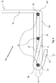
- each vertical wall 3 and the base 2 at the bottom end 3a is ensured by the provision of one hook 5 for each vertical rod 4 of the vertical wall 3, which may take different forms according to the relevant vertical wall.
- connection is provided by a U-shaped hook 5a, known in the art, for joining each vertical rod 4 to the first vertical rod 2a of the base 2.
- Such U-shaped hook system 5a is also used to join the vertical walls 3 together; according to the present embodiment, the U-shaped hook 5a is provided at the ends of the horizontal rods of the long vertical walls 3c, for connecting each horizontal rod to the first vertical rod of each adjacent short vertical wall 3c.
- a J-like conformation is used for the hook 5b for connecting each vertical rod 4 of the long vertical walls 3c.
- the J-shaped hook 5b comprises a first vertical portion 5c, substantially perpendicular to the base surface, and continues with a first loop 5d which encircles the first horizontal rod 2b of the base 2.
- the first horizontal rod 2b is the outermost rod of all the horizontal rods in the base 2 and is followed by a second horizontal rod 2c and a third horizontal rod 2d, in this order.
- the first loop 5d engages the first horizontal rod 2b and defines a curve at a substantially 90° angle.
- the hook 5d Downstream from the first loop 5d, the hook 5d has a first straight portion 5e, substantially parallel to the support surface.
- support surface is intended to designate, for example, the area of the ground upon which the cage is designed to be placed, or the top surface of a cage upon which an additional cage is stacked to form a barrier and/or a retaining wall.
- the portion 5e extends below the base 2, reaching past the second horizontal rod 2c.
- This first straight portion 5e is useful to impart proper stability to the cage 1 during unloading and assembly, i.e. when no load of inert material is present. Also, it facilitates stacking of a plurality of cages for creating complex structures.
- a second straight portion 5f is provided, which extends in a direction incident on the support surface, to extend above the third horizontal rod 2d.
- the second straight portion 5f has an imaginary projection on the plane normal to the support surface and to the long vertical wall 3c which, with reference to the trigonometric circumference, has an angular coefficient that lies in the second quadrant.
- the second straight portion 5f is inclined to the support surface at an angle ⁇ ranging from 10° e 70°.
- a second loop 5g and a third straight portion 5h are provided for anchoring the long vertical wall 3c to the base 2.
- the loop 5g encircles the aforementioned third horizontal rod 2d.
- the second loop 5g engages the third horizontal rod 2d and defines a curve at a substantially 180° angle.
- the third straight portion 5h extends in a direction incident on the support surface.
- the third straight portion 5h has an imaginary projection on the plane normal to the support surface and to the long vertical wall 3c which, with reference to the trigonometric circumference, has an angular coefficient that lies in the second quadrant.
- the third straight portion 5h is inclined to the support surface by an angle ⁇ which, according to a preferred embodiment, is equal to the aforementioned angle ⁇ , such that the second straight portion 5f and the third straight portion 5h are preferably parallel.
- the angle ⁇ may generally assume values that can be also other (greater or smaller) than those mentioned above for the angle ⁇ .
- the second loop 5g and the third straight portion 5h are designed to ensure safety of the hook 5b and impart optimized structural stability to the cage 1 during loading and transport.
- the cage 1 comprises at least two comb-like hooks 7 comprising a substantially flat quadrangular body 7a extending in a longitudinal direction, and having a top edge 7b and a bottom edge 7c.
- the comb-like hook 7 comprises a plurality of comb teeth 7d, substantially extending the body 7a and bent at least partially into a U shape.
- Each comb-like hook 7 also comprises a plurality of holes 7e formed in the body 7a and longitudinally arranged along such body 7a.
- Each of the two long vertical walls 3c of the cage 1 comprises, as described above, a plurality of horizontal rods 6, including a top horizontal rod 6a characterized by being the farthest rod from the base 2.
- each comb-like hook 7 partially engages the top horizontal rod 6a by the aforementioned U-shaped comb teeth 7d, while the comb-like hook 7 is left free of rotating about the top horizontal bar 6a.
- the cage 1 is lifted by hoist means, not shown, which engage the cage 1 at the holes 7e of the two comb-like hooks 7, the latter assuming thus a position transverse to the support surface.
- the cage 1 Once the cage 1 has been positioned, it is released from the hoist means and the comb-like hooks 7 are rotated to such a position that the body 7a, substantially parallel to the support surface, will rest on the inert material itself or on a closing surface 8, if any.
- these comb-like hooks afford simple and practical transport, and can assume a position that ensures the lack of bulk transverse to the support surface once transport has been completed, thereby allowing a plurality of cages to be stacked one above the other to form complex structures such as barriers and/or retaining walls.
Landscapes
- Engineering & Computer Science (AREA)
- Environmental & Geological Engineering (AREA)
- Life Sciences & Earth Sciences (AREA)
- General Life Sciences & Earth Sciences (AREA)
- Mining & Mineral Resources (AREA)
- Paleontology (AREA)
- Civil Engineering (AREA)
- General Engineering & Computer Science (AREA)
- Structural Engineering (AREA)
- Pit Excavations, Shoring, Fill Or Stabilisation Of Slopes (AREA)
Claims (9)
- Cage (1) pour contenir du matériel inerte, qui comprend une pluralité de surfaces de treillis métallique composées de tiges horizontales et verticales en motif entrecroisé, ladite pluralité de surfaces comprenant une base (2) et des parois verticales (3), chacune desdites parois verticales (3) étant reliée à son extrémité inférieure (3a) à ladite base (2) et aux parois verticales adjacentes à ses extrémités latérales respectives (3b) pour définir ainsi un espace à l'intérieur de ladite cage (1) pour contenir le matériel inerte, où chaque tige verticale (4) d'au moins une paroi verticale (3) comporte un crochet (5b) à ladite extrémité inférieure (3a), lequel crochet comprend :- une partie verticale (5c) sensiblement perpendiculaire à la surface de support ;- une première boucle (5d) qui prolonge ladite partie verticale (5c) pour envelopper une première tige horizontale (2b) de ladite base (2), qui est la tige la plus extérieure d'une pluralité de tiges horizontales (2o) de ladite base (2), près d'un bord de ladite base (2) ;- une première partie droite (5e), qui prolonge ladite première boucle (5d), parallèlement à une surface de support et en dessous de ladite base (2) en dépassant une seconde tige horizontale (2c) adjacente à ladite première tige horizontale (2b), lequel crochet étant en outre caractérisé par:- une seconde partie droite (5f), qui prolonge ladite première partie droite (5e) dans une direction incidente sur la surface de support, pour s'étendre au-dessus d'une troisième tige horizontale (2d), adjacente à ladite seconde tige horizontale (2c) ;- une seconde boucle (5g), qui prolonge ladite seconde partie droite (5f) pour envelopper ladite troisième tige horizontale (2d).
- Cage (1) selon la revendication 1, dans laquelle ledit crochet (5b) comprend une troisième partie droite (5h), qui prolonge ladite seconde boucle (5g) dans une direction incidente sur la surface de support, ladite troisième partie droite (5h) étant sensiblement parallèle à ladite seconde partie droite (5f).
- Cage (1) selon l'une quelconque des revendications précédentes, dans laquelle ladite deuxième partie droite (50) est inclinée par rapport à la surface de support selon un angle α, ledit angle allant de 10° à 70°.
- Cage (1) selon la revendication 2, dans laquelle ladite troisième section droite (5h) est inclinée par rapport à la surface de support selon un angle β.
- Cage (1) selon la revendication 1, dans laquelle chaque tige verticale (4) d'au moins une paroi verticale (3) présente un crochet (5a) au moins partiellement en forme de U à ladite extrémité inférieure (3a) pour relier ladite tige verticale (4) à une première tige verticale (2a) de ladite base (2), ladite première tige verticale (2a) étant la tige la plus extérieure des tiges verticales (2v) de ladite base (2).
- Cage (1) selon l'une quelconque des revendications précédentes, dans laquelle lesdites parois verticales (3) comprennent des tiges horizontales (6), lesdites tiges horizontales (6) comprenant une tige horizontale supérieure (6a), ladite tige horizontale supérieure (6a) étant la tige la plus éloignée de ladite base (2) parmi toutes lesdites tiges horizontales (6).
- Cage (1) selon l'une quelconque des revendications précédentes, caractérisée en ce qu'elle comprend au moins un crochet en forme de peigne (7).
- Cage (1) selon la revendication 7, dans laquelle ledit au moins un crochet en forme de peigne (7) comprend :- un corps quadrangulaire sensiblement plat s'étendant dans une direction longitudinale, ledit corps (7a) ayant un bord supérieur (7b) et un bord inférieur (7c) ;- une pluralité de dents de peigne (7d) prolongeant ledit corps (7a) au niveau dudit bord inférieur (7c) dudit corps (7a), lesdites dents de peigne (7d) ayant une configuration au moins partiellement en forme de U ;- une pluralité de trous (7e) formés dans ledit corps (7a) et disposés longitudinalement le long dudit corps (7a).
- Cage (1) selon la revendication 8, dans laquelle ladite pluralité de dents de peigne (7d) viennent en prise au moins partiellement avec ladite tige horizontale supérieure (6a).
Applications Claiming Priority (1)
| Application Number | Priority Date | Filing Date | Title |
|---|---|---|---|
| ITMI20150448 | 2015-03-27 |
Publications (2)
| Publication Number | Publication Date |
|---|---|
| EP3073017A1 EP3073017A1 (fr) | 2016-09-28 |
| EP3073017B1 true EP3073017B1 (fr) | 2017-12-13 |
Family
ID=53539778
Family Applications (1)
| Application Number | Title | Priority Date | Filing Date |
|---|---|---|---|
| EP16160909.4A Active EP3073017B1 (fr) | 2015-03-27 | 2016-03-17 | Gabion |
Country Status (2)
| Country | Link |
|---|---|
| EP (1) | EP3073017B1 (fr) |
| MA (1) | MA40429A (fr) |
Families Citing this family (2)
| Publication number | Priority date | Publication date | Assignee | Title |
|---|---|---|---|---|
| FR3083551B1 (fr) * | 2018-07-03 | 2020-12-25 | Terre Armee Int | Systeme de protection contre un impact |
| IT202000029318A1 (it) * | 2020-12-01 | 2022-06-01 | Metallurgica Ledrense Soc Cooperativa | Gabbione di contenimento perfezionato per il contenimento ed il trasporto di materiale inerte |
Family Cites Families (2)
| Publication number | Priority date | Publication date | Assignee | Title |
|---|---|---|---|---|
| DE20015651U1 (de) | 2000-09-08 | 2000-11-30 | Weber, Rainer, 54578 Walsdorf | Steinkorb |
| ITBS20110144A1 (it) * | 2011-10-14 | 2013-04-15 | Novaporfidi S R L | Cesto per materiale inerte |
-
2016
- 2016-03-16 MA MA040429A patent/MA40429A/fr unknown
- 2016-03-17 EP EP16160909.4A patent/EP3073017B1/fr active Active
Non-Patent Citations (1)
| Title |
|---|
| None * |
Also Published As
| Publication number | Publication date |
|---|---|
| EP3073017A1 (fr) | 2016-09-28 |
| MA40429A (fr) | 2017-12-12 |
Similar Documents
| Publication | Publication Date | Title |
|---|---|---|
| CA2798142C (fr) | Systeme de terre stabilise mecaniquement et procede associe | |
| US7837414B2 (en) | Gabions | |
| CN107567526B (zh) | 混凝土部件制造用模块、位移体以及格栅用于制造模块和混凝土部件的用途 | |
| US7001110B2 (en) | Precast concrete retaining wall | |
| KR101519086B1 (ko) | 프리캐스트 t형 거더를 이용한 교량 및 교량 시공방법 | |
| US20090285639A1 (en) | Soil reinforcing retaining wall anchor | |
| JP6241325B2 (ja) | 堤体、堤体構成部材および堤体の施工方法 | |
| JP5023371B2 (ja) | 石詰籠 | |
| EP3073017A1 (fr) | Gabion | |
| CN105064614A (zh) | 具有能提供纵筋横向约束力的箍筋及其制造方法 | |
| EP2581499B1 (fr) | gabion | |
| EP4256137B1 (fr) | Gabion de retenue amélioré destiné à contenir et à transporter un matériau inerte | |
| JP2015036479A (ja) | 構造物構築用セット、構造物を構築する方法 | |
| US8632281B2 (en) | Mechanically stabilized earth system and method | |
| KR101930001B1 (ko) | 개비온 펜스 및 개비온 펜스 시공방법 | |
| JP2000045302A (ja) | 土木構築物用施工石、土木構築物用施工石の製造方法、土木構築物用施工石の使用方法、土木構築物用施工石ユニット及び土木構築物 | |
| JP7366361B2 (ja) | 鉄筋スペーサー及びその製造方法、並びにそれを用いた鉄筋保持工法 | |
| US20150132070A1 (en) | Mechanically stabilized earth system and method | |
| JP3650050B2 (ja) | 土木構築物用施工石 | |
| JP3692461B1 (ja) | せん断補強筋と配筋構造 | |
| JPH06108483A (ja) | 擁壁の段積み方法及び擁壁用コンクリートブロック | |
| EP3414401B1 (fr) | Cage destinée à contenir des matériaux en pierre destinée à la fabrication de structures de murs en pierre sèche | |
| US20190368198A1 (en) | Reinforcing bar positioner and method | |
| KR101392851B1 (ko) | 원형 단면 철근 콘크리트 기둥의 시공공법 | |
| JP2011089384A (ja) | 閉鎖型フープ |
Legal Events
| Date | Code | Title | Description |
|---|---|---|---|
| PUAI | Public reference made under article 153(3) epc to a published international application that has entered the european phase |
Free format text: ORIGINAL CODE: 0009012 |
|
| AK | Designated contracting states |
Kind code of ref document: A1 Designated state(s): AL AT BE BG CH CY CZ DE DK EE ES FI FR GB GR HR HU IE IS IT LI LT LU LV MC MK MT NL NO PL PT RO RS SE SI SK SM TR |
|
| AX | Request for extension of the european patent |
Extension state: BA ME |
|
| STAA | Information on the status of an ep patent application or granted ep patent |
Free format text: STATUS: REQUEST FOR EXAMINATION WAS MADE |
|
| 17P | Request for examination filed |
Effective date: 20170222 |
|
| RAV | Requested validation state of the european patent: fee paid |
Extension state: MA Effective date: 20170222 Extension state: MD Effective date: 20170222 |
|
| RAX | Requested extension states of the european patent have changed |
Extension state: BA Payment date: 20170222 Extension state: ME Payment date: 20170222 |
|
| RBV | Designated contracting states (corrected) |
Designated state(s): AL AT BE BG CH CY CZ DE DK EE ES FI FR GB GR HR HU IE IS IT LI LT LU LV MC MK MT NL NO PL PT RO RS SE SI SK SM TR |
|
| GRAP | Despatch of communication of intention to grant a patent |
Free format text: ORIGINAL CODE: EPIDOSNIGR1 |
|
| STAA | Information on the status of an ep patent application or granted ep patent |
Free format text: STATUS: GRANT OF PATENT IS INTENDED |
|
| INTG | Intention to grant announced |
Effective date: 20170704 |
|
| GRAS | Grant fee paid |
Free format text: ORIGINAL CODE: EPIDOSNIGR3 |
|
| GRAA | (expected) grant |
Free format text: ORIGINAL CODE: 0009210 |
|
| STAA | Information on the status of an ep patent application or granted ep patent |
Free format text: STATUS: THE PATENT HAS BEEN GRANTED |
|
| REG | Reference to a national code |
Ref country code: GB Ref legal event code: FG4D |
|
| REG | Reference to a national code |
Ref country code: AT Ref legal event code: REF Ref document number: 954487 Country of ref document: AT Kind code of ref document: T Effective date: 20171215 Ref country code: CH Ref legal event code: EP |
|
| REG | Reference to a national code |
Ref country code: IE Ref legal event code: FG4D |
|
| REG | Reference to a national code |
Ref country code: DE Ref legal event code: R096 Ref document number: 602016001048 Country of ref document: DE |
|
| REG | Reference to a national code |
Ref country code: FR Ref legal event code: PLFP Year of fee payment: 3 |
|
| REG | Reference to a national code |
Ref country code: NL Ref legal event code: MP Effective date: 20171213 |
|
| REG | Reference to a national code |
Ref country code: LT Ref legal event code: MG4D |
|
| PG25 | Lapsed in a contracting state [announced via postgrant information from national office to epo] |
Ref country code: LT Free format text: LAPSE BECAUSE OF FAILURE TO SUBMIT A TRANSLATION OF THE DESCRIPTION OR TO PAY THE FEE WITHIN THE PRESCRIBED TIME-LIMIT Effective date: 20171213 Ref country code: NO Free format text: LAPSE BECAUSE OF FAILURE TO SUBMIT A TRANSLATION OF THE DESCRIPTION OR TO PAY THE FEE WITHIN THE PRESCRIBED TIME-LIMIT Effective date: 20180313 Ref country code: FI Free format text: LAPSE BECAUSE OF FAILURE TO SUBMIT A TRANSLATION OF THE DESCRIPTION OR TO PAY THE FEE WITHIN THE PRESCRIBED TIME-LIMIT Effective date: 20171213 Ref country code: SE Free format text: LAPSE BECAUSE OF FAILURE TO SUBMIT A TRANSLATION OF THE DESCRIPTION OR TO PAY THE FEE WITHIN THE PRESCRIBED TIME-LIMIT Effective date: 20171213 |
|
| PG25 | Lapsed in a contracting state [announced via postgrant information from national office to epo] |
Ref country code: HR Free format text: LAPSE BECAUSE OF FAILURE TO SUBMIT A TRANSLATION OF THE DESCRIPTION OR TO PAY THE FEE WITHIN THE PRESCRIBED TIME-LIMIT Effective date: 20171213 Ref country code: LV Free format text: LAPSE BECAUSE OF FAILURE TO SUBMIT A TRANSLATION OF THE DESCRIPTION OR TO PAY THE FEE WITHIN THE PRESCRIBED TIME-LIMIT Effective date: 20171213 Ref country code: RS Free format text: LAPSE BECAUSE OF FAILURE TO SUBMIT A TRANSLATION OF THE DESCRIPTION OR TO PAY THE FEE WITHIN THE PRESCRIBED TIME-LIMIT Effective date: 20171213 Ref country code: GR Free format text: LAPSE BECAUSE OF FAILURE TO SUBMIT A TRANSLATION OF THE DESCRIPTION OR TO PAY THE FEE WITHIN THE PRESCRIBED TIME-LIMIT Effective date: 20180314 Ref country code: BG Free format text: LAPSE BECAUSE OF FAILURE TO SUBMIT A TRANSLATION OF THE DESCRIPTION OR TO PAY THE FEE WITHIN THE PRESCRIBED TIME-LIMIT Effective date: 20180313 |
|
| PG25 | Lapsed in a contracting state [announced via postgrant information from national office to epo] |
Ref country code: NL Free format text: LAPSE BECAUSE OF FAILURE TO SUBMIT A TRANSLATION OF THE DESCRIPTION OR TO PAY THE FEE WITHIN THE PRESCRIBED TIME-LIMIT Effective date: 20171213 |
|
| PG25 | Lapsed in a contracting state [announced via postgrant information from national office to epo] |
Ref country code: SK Free format text: LAPSE BECAUSE OF FAILURE TO SUBMIT A TRANSLATION OF THE DESCRIPTION OR TO PAY THE FEE WITHIN THE PRESCRIBED TIME-LIMIT Effective date: 20171213 Ref country code: ES Free format text: LAPSE BECAUSE OF FAILURE TO SUBMIT A TRANSLATION OF THE DESCRIPTION OR TO PAY THE FEE WITHIN THE PRESCRIBED TIME-LIMIT Effective date: 20171213 Ref country code: CY Free format text: LAPSE BECAUSE OF FAILURE TO SUBMIT A TRANSLATION OF THE DESCRIPTION OR TO PAY THE FEE WITHIN THE PRESCRIBED TIME-LIMIT Effective date: 20171213 Ref country code: CZ Free format text: LAPSE BECAUSE OF FAILURE TO SUBMIT A TRANSLATION OF THE DESCRIPTION OR TO PAY THE FEE WITHIN THE PRESCRIBED TIME-LIMIT Effective date: 20171213 Ref country code: EE Free format text: LAPSE BECAUSE OF FAILURE TO SUBMIT A TRANSLATION OF THE DESCRIPTION OR TO PAY THE FEE WITHIN THE PRESCRIBED TIME-LIMIT Effective date: 20171213 |
|
| PG25 | Lapsed in a contracting state [announced via postgrant information from national office to epo] |
Ref country code: RO Free format text: LAPSE BECAUSE OF FAILURE TO SUBMIT A TRANSLATION OF THE DESCRIPTION OR TO PAY THE FEE WITHIN THE PRESCRIBED TIME-LIMIT Effective date: 20171213 Ref country code: IS Free format text: LAPSE BECAUSE OF FAILURE TO SUBMIT A TRANSLATION OF THE DESCRIPTION OR TO PAY THE FEE WITHIN THE PRESCRIBED TIME-LIMIT Effective date: 20180413 Ref country code: SM Free format text: LAPSE BECAUSE OF FAILURE TO SUBMIT A TRANSLATION OF THE DESCRIPTION OR TO PAY THE FEE WITHIN THE PRESCRIBED TIME-LIMIT Effective date: 20171213 Ref country code: PL Free format text: LAPSE BECAUSE OF FAILURE TO SUBMIT A TRANSLATION OF THE DESCRIPTION OR TO PAY THE FEE WITHIN THE PRESCRIBED TIME-LIMIT Effective date: 20171213 |
|
| REG | Reference to a national code |
Ref country code: DE Ref legal event code: R097 Ref document number: 602016001048 Country of ref document: DE |
|
| PLBE | No opposition filed within time limit |
Free format text: ORIGINAL CODE: 0009261 |
|
| STAA | Information on the status of an ep patent application or granted ep patent |
Free format text: STATUS: NO OPPOSITION FILED WITHIN TIME LIMIT |
|
| VS25 | Lapsed in a validation state [announced via postgrant information from nat. office to epo] |
Ref country code: MD Free format text: LAPSE BECAUSE OF FAILURE TO SUBMIT A TRANSLATION OF THE DESCRIPTION OR TO PAY THE FEE WITHIN THE PRESCRIBED TIME-LIMIT Effective date: 20171213 |
|
| 26N | No opposition filed |
Effective date: 20180914 |
|
| PG25 | Lapsed in a contracting state [announced via postgrant information from national office to epo] |
Ref country code: MC Free format text: LAPSE BECAUSE OF FAILURE TO SUBMIT A TRANSLATION OF THE DESCRIPTION OR TO PAY THE FEE WITHIN THE PRESCRIBED TIME-LIMIT Effective date: 20171213 Ref country code: DK Free format text: LAPSE BECAUSE OF FAILURE TO SUBMIT A TRANSLATION OF THE DESCRIPTION OR TO PAY THE FEE WITHIN THE PRESCRIBED TIME-LIMIT Effective date: 20171213 |
|
| REG | Reference to a national code |
Ref country code: BE Ref legal event code: MM Effective date: 20180331 |
|
| REG | Reference to a national code |
Ref country code: IE Ref legal event code: MM4A |
|
| PG25 | Lapsed in a contracting state [announced via postgrant information from national office to epo] |
Ref country code: LU Free format text: LAPSE BECAUSE OF NON-PAYMENT OF DUE FEES Effective date: 20180317 |
|
| PG25 | Lapsed in a contracting state [announced via postgrant information from national office to epo] |
Ref country code: IE Free format text: LAPSE BECAUSE OF NON-PAYMENT OF DUE FEES Effective date: 20180317 |
|
| PG25 | Lapsed in a contracting state [announced via postgrant information from national office to epo] |
Ref country code: BE Free format text: LAPSE BECAUSE OF NON-PAYMENT OF DUE FEES Effective date: 20180331 Ref country code: SI Free format text: LAPSE BECAUSE OF FAILURE TO SUBMIT A TRANSLATION OF THE DESCRIPTION OR TO PAY THE FEE WITHIN THE PRESCRIBED TIME-LIMIT Effective date: 20171213 |
|
| VS25 | Lapsed in a validation state [announced via postgrant information from nat. office to epo] |
Ref country code: MA Free format text: LAPSE BECAUSE OF FAILURE TO SUBMIT A TRANSLATION OF THE DESCRIPTION OR TO PAY THE FEE WITHIN THE PRESCRIBED TIME-LIMIT; INVALID AB INITIO Effective date: 20160317 |
|
| PG25 | Lapsed in a contracting state [announced via postgrant information from national office to epo] |
Ref country code: MT Free format text: LAPSE BECAUSE OF NON-PAYMENT OF DUE FEES Effective date: 20180317 |
|
| PG25 | Lapsed in a contracting state [announced via postgrant information from national office to epo] |
Ref country code: TR Free format text: LAPSE BECAUSE OF FAILURE TO SUBMIT A TRANSLATION OF THE DESCRIPTION OR TO PAY THE FEE WITHIN THE PRESCRIBED TIME-LIMIT Effective date: 20171213 |
|
| REG | Reference to a national code |
Ref country code: AT Ref legal event code: UEP Ref document number: 954487 Country of ref document: AT Kind code of ref document: T Effective date: 20171213 |
|
| PG25 | Lapsed in a contracting state [announced via postgrant information from national office to epo] |
Ref country code: PT Free format text: LAPSE BECAUSE OF FAILURE TO SUBMIT A TRANSLATION OF THE DESCRIPTION OR TO PAY THE FEE WITHIN THE PRESCRIBED TIME-LIMIT Effective date: 20171213 |
|
| PG25 | Lapsed in a contracting state [announced via postgrant information from national office to epo] |
Ref country code: MK Free format text: LAPSE BECAUSE OF NON-PAYMENT OF DUE FEES Effective date: 20171213 Ref country code: HU Free format text: LAPSE BECAUSE OF FAILURE TO SUBMIT A TRANSLATION OF THE DESCRIPTION OR TO PAY THE FEE WITHIN THE PRESCRIBED TIME-LIMIT; INVALID AB INITIO Effective date: 20160317 |
|
| PG25 | Lapsed in a contracting state [announced via postgrant information from national office to epo] |
Ref country code: AL Free format text: LAPSE BECAUSE OF FAILURE TO SUBMIT A TRANSLATION OF THE DESCRIPTION OR TO PAY THE FEE WITHIN THE PRESCRIBED TIME-LIMIT Effective date: 20171213 |
|
| P01 | Opt-out of the competence of the unified patent court (upc) registered |
Effective date: 20230808 |
|
| PGFP | Annual fee paid to national office [announced via postgrant information from national office to epo] |
Ref country code: IT Payment date: 20250327 Year of fee payment: 10 |
|
| PGFP | Annual fee paid to national office [announced via postgrant information from national office to epo] |
Ref country code: CH Payment date: 20250401 Year of fee payment: 10 |
|
| REG | Reference to a national code |
Ref country code: CH Ref legal event code: U11 Free format text: ST27 STATUS EVENT CODE: U-0-0-U10-U11 (AS PROVIDED BY THE NATIONAL OFFICE) Effective date: 20260401 |
|
| PGFP | Annual fee paid to national office [announced via postgrant information from national office to epo] |
Ref country code: GB Payment date: 20260304 Year of fee payment: 11 |
|
| PGFP | Annual fee paid to national office [announced via postgrant information from national office to epo] |
Ref country code: DE Payment date: 20260320 Year of fee payment: 11 |
|
| PGFP | Annual fee paid to national office [announced via postgrant information from national office to epo] |
Ref country code: AT Payment date: 20260318 Year of fee payment: 11 |
|
| PGFP | Annual fee paid to national office [announced via postgrant information from national office to epo] |
Ref country code: FR Payment date: 20260323 Year of fee payment: 11 |