EP3073111A1 - Ensemble piston et élément à glissement pour unité hydraulique - Google Patents
Ensemble piston et élément à glissement pour unité hydraulique Download PDFInfo
- Publication number
- EP3073111A1 EP3073111A1 EP16161698.2A EP16161698A EP3073111A1 EP 3073111 A1 EP3073111 A1 EP 3073111A1 EP 16161698 A EP16161698 A EP 16161698A EP 3073111 A1 EP3073111 A1 EP 3073111A1
- Authority
- EP
- European Patent Office
- Prior art keywords
- piston
- slipper
- ball
- length
- ratio
- Prior art date
- Legal status (The legal status is an assumption and is not a legal conclusion. Google has not performed a legal analysis and makes no representation as to the accuracy of the status listed.)
- Withdrawn
Links
- 230000000712 assembly Effects 0.000 claims description 18
- 238000000429 assembly Methods 0.000 claims description 18
- 238000000034 method Methods 0.000 claims description 10
- 238000006073 displacement reaction Methods 0.000 description 5
- 230000000717 retained effect Effects 0.000 description 4
- 230000033001 locomotion Effects 0.000 description 3
- 239000012530 fluid Substances 0.000 description 2
- 230000004075 alteration Effects 0.000 description 1
- 230000005540 biological transmission Effects 0.000 description 1
- 238000004891 communication Methods 0.000 description 1
- 230000008878 coupling Effects 0.000 description 1
- 238000010168 coupling process Methods 0.000 description 1
- 238000005859 coupling reaction Methods 0.000 description 1
- 230000001419 dependent effect Effects 0.000 description 1
- 238000010586 diagram Methods 0.000 description 1
- 230000006353 environmental stress Effects 0.000 description 1
- 230000002706 hydrostatic effect Effects 0.000 description 1
- 210000003734 kidney Anatomy 0.000 description 1
- 239000000463 material Substances 0.000 description 1
- 230000007246 mechanism Effects 0.000 description 1
- 230000009467 reduction Effects 0.000 description 1
- 230000004044 response Effects 0.000 description 1
- 230000035882 stress Effects 0.000 description 1
- 238000006467 substitution reaction Methods 0.000 description 1
Images
Classifications
-
- F—MECHANICAL ENGINEERING; LIGHTING; HEATING; WEAPONS; BLASTING
- F04—POSITIVE - DISPLACEMENT MACHINES FOR LIQUIDS; PUMPS FOR LIQUIDS OR ELASTIC FLUIDS
- F04B—POSITIVE-DISPLACEMENT MACHINES FOR LIQUIDS; PUMPS
- F04B1/00—Multi-cylinder machines or pumps characterised by number or arrangement of cylinders
- F04B1/12—Multi-cylinder machines or pumps characterised by number or arrangement of cylinders having cylinder axes coaxial with, or parallel or inclined to, main shaft axis
- F04B1/122—Details or component parts, e.g. valves, sealings or lubrication means
- F04B1/124—Pistons
-
- F—MECHANICAL ENGINEERING; LIGHTING; HEATING; WEAPONS; BLASTING
- F01—MACHINES OR ENGINES IN GENERAL; ENGINE PLANTS IN GENERAL; STEAM ENGINES
- F01B—MACHINES OR ENGINES, IN GENERAL OR OF POSITIVE-DISPLACEMENT TYPE, e.g. STEAM ENGINES
- F01B3/00—Reciprocating-piston machines or engines with cylinder axes coaxial with, or parallel or inclined to, main shaft axis
- F01B3/0082—Details
- F01B3/0085—Pistons
-
- F—MECHANICAL ENGINEERING; LIGHTING; HEATING; WEAPONS; BLASTING
- F04—POSITIVE - DISPLACEMENT MACHINES FOR LIQUIDS; PUMPS FOR LIQUIDS OR ELASTIC FLUIDS
- F04B—POSITIVE-DISPLACEMENT MACHINES FOR LIQUIDS; PUMPS
- F04B1/00—Multi-cylinder machines or pumps characterised by number or arrangement of cylinders
- F04B1/12—Multi-cylinder machines or pumps characterised by number or arrangement of cylinders having cylinder axes coaxial with, or parallel or inclined to, main shaft axis
- F04B1/122—Details or component parts, e.g. valves, sealings or lubrication means
- F04B1/124—Pistons
- F04B1/126—Piston shoe retaining means
-
- F—MECHANICAL ENGINEERING; LIGHTING; HEATING; WEAPONS; BLASTING
- F16—ENGINEERING ELEMENTS AND UNITS; GENERAL MEASURES FOR PRODUCING AND MAINTAINING EFFECTIVE FUNCTIONING OF MACHINES OR INSTALLATIONS; THERMAL INSULATION IN GENERAL
- F16H—GEARING
- F16H39/00—Rotary fluid gearing using pumps and motors of the volumetric type, i.e. passing a predetermined volume of fluid per revolution
- F16H39/04—Rotary fluid gearing using pumps and motors of the volumetric type, i.e. passing a predetermined volume of fluid per revolution with liquid motor and pump combined in one unit
- F16H39/06—Rotary fluid gearing using pumps and motors of the volumetric type, i.e. passing a predetermined volume of fluid per revolution with liquid motor and pump combined in one unit pump and motor being of the same type
- F16H39/08—Rotary fluid gearing using pumps and motors of the volumetric type, i.e. passing a predetermined volume of fluid per revolution with liquid motor and pump combined in one unit pump and motor being of the same type each with one main shaft and provided with pistons reciprocating in cylinders
- F16H39/10—Rotary fluid gearing using pumps and motors of the volumetric type, i.e. passing a predetermined volume of fluid per revolution with liquid motor and pump combined in one unit pump and motor being of the same type each with one main shaft and provided with pistons reciprocating in cylinders with cylinders arranged around, and parallel or approximately parallel to the main axis of the gearing
Definitions
- Embodiments of this invention generally relate to an integrated drive generator, and more particularly, to a piston and slipper assembly of a hydraulic unit of an integrated drive generator.
- Aircraft currently rely on electrical, pneumatic, and hydraulic systems for secondary power.
- a typical electrical system utilizes an integrated drive generator coupled to each engine of an aircraft to provide fixed frequency power to a power distribution system and associated loads.
- One type of integrated drive generator includes a generator, a hydraulic unit, and a differential assembly arranged in a common housing.
- the differential assembly is operably coupled to an aircraft engine, such as a gas turbine engine, via an input shaft. The rotational speed of the input shaft varies during operation of the engine.
- the hydraulic unit cooperates with the differential assembly to provide a constant speed to the generator throughout engine operation.
- a piston and slipper assembly of a hydraulic unit includes a slipper and a piston.
- the slipper includes a swashplate interface having a balance land and a piston ball socket extending to a ball engagement end, where a slipper length is defined between the balance land and the ball engagement end.
- the piston includes a piston ball member having a ball and a piston body. The ball engages with the piston ball socket.
- the piston body is coaxially fixed within a piston sleeve.
- the piston sleeve defines a piston diameter, and a piston length is defined between a centroid of the ball and a piston end face.
- a ratio of the piston diameter to the slipper length is between 1.35 and 1.42, and a ratio of the piston length to the piston diameter is between 2.51 and 2.55.
- a method of assembling a hydraulic unit includes inserting a plurality of pistons of a plurality of piston and slipper assemblies into a cylinder block assembly.
- Each of the piston and slipper assemblies has a slipper including a swashplate interface having a balance land and a piston ball socket extending to a ball engagement end.
- Each of the piston and slipper assemblies also has a piston including a piston ball member having a ball and a piston body. The ball engages with the piston ball socket.
- the piston body is coaxially fixed within a piston sleeve.
- the piston sleeve defines a piston diameter, a piston length is defined between a centroid of the ball and a piston end face, and a slipper length is defined between the balance land and the ball engagement end.
- a ratio of the piston diameter to the slipper length is between 1.35 and 1.42, and a ratio of the piston length to the piston diameter is between 2.51 and 2.55.
- the balance land of each of the piston and slipper assemblies is placed in contact with a swashplate. The slipper of each of the piston and slipper assemblies is retained to maintain contact with the swashplate.
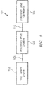
- the generator system 100 includes a gas turbine engine 102 that is configured to rotationally drive an integrated drive generator 106 through an accessory drive gearbox 104 mounted on the gas turbine engine 102.
- the accessory drive gearbox 104 is coupled to a spool 108 of the gas turbine engine 102, and the speed of the spool 108 varies throughout the entire operation of the gas turbine engine 102, depending on operational characteristics, such as high altitude cruising flight or take-off of an aircraft in which the generator system 100 is installed.
- An input shaft 110 is configured to transfer rotational energy to the integrated drive generator 106 from the accessory drive gearbox 104.
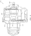
- FIG. 2 An example of an integrated drive generator 200 including a housing 202 is shown in FIG. 2 .
- the integrated drive generator 200 includes an input shaft 204 configured to receive rotational drive from an accessory drive gearbox (see FIG. 1 ).
- the rotational speed of the input shaft 204 varies depending upon the operation of the engine (see FIG. 1 ).
- a hydraulic unit 206 cooperates with a differential assembly 208 to convert the variable rotational speed from the input shaft 204 to a fixed rotational output speed that is transferred to a generator 210.
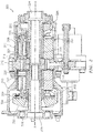
- the hydraulic unit 300 includes a variable displacement hydraulic pump 302 and a fixed displacement hydraulic motor 304.
- the variable displacement hydraulic pump 302 and the fixed displacement hydraulic motor 304 have respective cylinder block assemblies 306 and 308 which are arranged for rotation about a common axis A within housings 310, 311 on opposite sides of a stationary port plate 312 of the hydraulic unit 300.
- the port plate 312 is formed with one or more kidneys or apertures 314 through which hydraulic fluid communication between the pump 302 and the motor 304 is established during normal operation of the hydraulic unit 300.
- a biasing mechanism 316 resiliently biases the cylinder block assemblies 306, 308 in the direction of the port plate 312.
- the operation of the hydraulic unit 300 in an integrated drive generator involves transmission of torque from an engine of the aircraft to an input, which rotates an input shaft 318 of the hydraulic unit 300 about axis A.
- the cylinder block assembly 306 of the pump 302 is connected to the input shaft 318 for rotation therewith.
- Pistons 320 within the cylinder block assembly 306 of the pump 302 are displaced during rotation an amount which is a function of the setting of a variable swashplate or wobbler 322 of the pump 302.
- Pistons 321 within the cylinder block assembly 308 of the motor 304 are displaced during rotation with respect to a fixed swash plate or wobbler 326 of the motor 304.
- the system may include nine pistons 320, 321 in each of the motor 304 and the pump 302, and nine apertures 314 may pass through the port plate 312.
- the number of apertures 314 is not dependent on the number of pistons 320, 321, and in some embodiments there may be five apertures 314 when nine pistons 320, 321 are employed.
- the number of pistons 320, 321 and the number apertures 314 may be varied without departing from the scope of the invention.
- Hydraulic fluid under pressure from the hydraulic pump 302 is delivered to the hydraulic motor 304 through the apertures 314 of port plate 312 for rotating the cylinder block assembly 308 and an output shaft 324 to which the cylinder block assembly 308 is fixedly connected.
- the swashplate or wobbler 326 of the motor 304 is fixedly configured so that an operating speed of the motor 304 is a function of a displacement of the pump 302.
- the rotary output from output shaft 324 is added to or subtracted from the rotary motion from the engine through a conventional differential gearing of an integrated drive generator for operating an electrical generator at a substantially constant rotational speed.
- the position of the variable wobbler 322 is adjusted in response to these detected speed variations for providing the necessary reduction or increase in the rotational speed for obtaining a desired constant output speed to the generator.
- the hydraulic unit 300 illustrated and described herein refers to the variable unit as a pump 302 and the fixed unit as a motor 304, hydraulic units having other configurations, such as where the variable unit functions as a motor and the hydraulic unit operates as a pump for example, are within the scope of the invention.
- the wobbler 322 is permitted to turn, rotate, tumble, and/or wobble about a retainer ball 328.
- the wobbler 322 is configured to wobble, etc., in part, as a result of the movement of the pistons 320, 321, respectively.
- a retainer ball 330 is configured to turn or rotate with respect to the wobbler 326.
- Each piston 320, 321 has a ball 332 (ball of piston 320 not labeled for clarity) on one end.
- the ball 332 of the pistons 320, 321 is retained within a slipper 334.
- the slipper 334 is retained by a slipper retainer 336.
- the slipper retainer 336 enables the slipper 334 to be held in contact with the wobbler 322, 326, thus enabling operational coupling and/or contact between the wobblers 322, 326 and the pistons 320, 321, respectively, of the pump 302 and the motor 304.
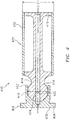
- FIG. 4 a cross-sectional schematic view of a piston and slipper assembly 400 of a hydraulic unit, such as the hydraulic unit 300 of FIG. 3 , is depicted in accordance with an embodiment of the invention.
- the piston and slipper assembly 400 includes a piston 402 and a slipper 404, such a piston 320, 321 and slipper 334 of FIG. 3 .
- the slipper 404 includes a swashplate interface 406 having a balance land 408 and a piston ball socket 410 extending to a ball engagement end 412.
- the balance land 408 provides force balancing with respect to a swashplate or wobbler, such as wobbler 326, 322 of FIG. 3 .
- the piston 402 includes a piston ball member 414 having a ball 416 and a piston body 418.
- the ball 416 engages with the piston ball socket 410 of the slipper 404.
- the piston body 418 is coaxially fixed within a piston sleeve 420 having a common central axis B.
- the central axis B is substantially parallel to the axis A of the hydraulic unit 300 of FIG. 3 when the piston 402 is installed therein.
- the piston sleeve 420 defines a piston diameter D1.
- the piston diameter D1 is sized to fit within a piston bore of a cylinder block assembly, such as the cylinder block assembly 306, 308 of FIG. 3 . In an embodiment, the piston diameter D1 is about 0.459 inches (1.166 cm).
- the piston 402 translates along axis B when in motion, and the slipper 404 pivots about the ball 416, where a centroid 422 of the ball 416 remains substantially aligned with a centroid 424 of the
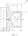
- FIG. 5 is a cross-sectional schematic view of the slipper 404 of the piston and slipper assembly 400 of FIG. 4 .
- a slipper length L1 is defined between the balance land 408 and the ball engagement end 412.
- a piston ball socket centroid offset L2 is defined between the balance land 408 and the centroid 424 of the piston ball socket 410.
- a balance land outer diameter D2 and a balance land inner diameter D3 are defined on the balance land 408 forming an annular region 426 between the balance land outer diameter D2 and the balance land inner diameter D3.
- a socket diameter D4 is defined within the piston ball socket 410 through the centroid 424.
- the slipper length L1 is about 0.331 inches (0.841 cm), and the piston ball socket centroid offset L2 is about 0.24 inches (0.610 cm).
- the balance land outer diameter D2 is about 0.519 inches (1.318 cm), and the balance land inner diameter D3 is about 0.39 inches (0.991 cm).
- the socket diameter D4 is about 0.294 inches (0.747 cm).
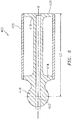
- FIG. 6 is a cross-sectional schematic view of the piston 402 of the piston and slipper assembly 400 of FIG. 4 .
- a piston length L3 is defined between the centroid 422 of the ball 416 and a piston end face 428.
- the piston length L3 is about 1.161 inches (2.949 cm).
- the piston end face 428 aligns an outer face of the piston body 418 of the piston ball member 414 with an edge of the piston sleeve 420.
- a number of ratios are defined between multiple features of the piston and slipper assembly 400 of FIGS. 4-6 .
- a ratio of the piston diameter D1 to the slipper length L1 is between 1.35 and 1.42, and a ratio of the piston length L3 to the piston diameter D1 is between 2.51 and 2.55.
- a ratio of the slipper length L1 to the piston ball socket centroid offset L2 is between 1.33 and 1.43.
- a ratio of the piston length L3 to the slipper length L1 is between 3.43 and 3.59.
- a ratio of the balance land outer diameter D2 to the piston diameter D1 is between 1.12 and 1.38.
- a ratio of the balance land outer diameter D2 to the slipper length L1 is between 1.53 and 1.61.
- a ratio of the balance land outer diameter D2 to the balance land inner diameter D3 is between 1.31 and 1.35.
- a ratio of the balance land inner diameter D3 to the slipper length L1 is between 1.15 and 1.21.
- a ratio of the piston diameter D1 to the balance land inner diameter D3 is between 1.16 and 1.19.
- a ratio of the piston length L3 to the balance land outer diameter D2 is between 2.21 and 2.26.
- a ratio of the piston length L3 to the balance land inner diameter D3 is between 2.94 and 3.01.
- a method of assembling a hydraulic unit includes inserting a plurality of pistons 402 of a plurality of piston and slipper assemblies 400 of FIG. 4 into a cylinder block assembly, such as cylinder block assembly 306, 348 of FIG. 3 .
- each of the piston and slipper assemblies 400 has a slipper 404 including a swashplate interface 406 having a balance land 408 and a piston ball socket 410 extending to a ball engagement end 412.
- Each of the piston and slipper assemblies 400 also has a piston 402 including a piston ball member 414 having a ball 416 and a piston body 418.
- the piston body 418 is coaxially fixed within a piston sleeve 420.
- the ball 416 engages with the piston ball socket 410.
- the balance land 408 of each of the piston and slipper assemblies 400 is placed in contact with a swashplate, such as wobbler 322, 326.
- the slipper 404 of each of the piston and slipper assemblies 400 is retained to maintain contact with the swashplate using, for example, slipper retainer 336 of FIG. 3 . It will be appreciated that the steps of the method can be done in an alternate order, such as retaining the slipper 404 of each of the piston and slipper assemblies 400 in contact with a swashplate prior to inserting the pistons 402 into the cylinder block assembly.
- the method can be repeated for each cylinder block assembly 306, 308.
Landscapes
- Engineering & Computer Science (AREA)
- General Engineering & Computer Science (AREA)
- Mechanical Engineering (AREA)
- Reciprocating Pumps (AREA)
Applications Claiming Priority (1)
| Application Number | Priority Date | Filing Date | Title |
|---|---|---|---|
| US14/667,726 US20160281691A1 (en) | 2015-03-25 | 2015-03-25 | Piston and slipper assembly for hydraulic unit |
Publications (1)
| Publication Number | Publication Date |
|---|---|
| EP3073111A1 true EP3073111A1 (fr) | 2016-09-28 |
Family
ID=55699384
Family Applications (1)
| Application Number | Title | Priority Date | Filing Date |
|---|---|---|---|
| EP16161698.2A Withdrawn EP3073111A1 (fr) | 2015-03-25 | 2016-03-22 | Ensemble piston et élément à glissement pour unité hydraulique |
Country Status (2)
| Country | Link |
|---|---|
| US (1) | US20160281691A1 (fr) |
| EP (1) | EP3073111A1 (fr) |
Citations (2)
| Publication number | Priority date | Publication date | Assignee | Title |
|---|---|---|---|---|
| US4478130A (en) * | 1981-03-19 | 1984-10-23 | Sundstrand Corporation | Arrangement for slipper cavitation erosion control and impact reduction |
| DE10314654A1 (de) * | 2003-04-01 | 2004-10-14 | Linde Ag | Hydrostatisches entlastetes Gleitlager |
Family Cites Families (3)
| Publication number | Priority date | Publication date | Assignee | Title |
|---|---|---|---|---|
| US3191543A (en) * | 1962-07-27 | 1965-06-29 | Sundstrand Corp | Pump or motor device |
| US3319575A (en) * | 1965-06-14 | 1967-05-16 | Sundstrand Corp | Piston |
| US5247794A (en) * | 1990-09-11 | 1993-09-28 | Sundstrand Corporation | Cylinder block positive hold-down for cold start-up |
-
2015
- 2015-03-25 US US14/667,726 patent/US20160281691A1/en not_active Abandoned
-
2016
- 2016-03-22 EP EP16161698.2A patent/EP3073111A1/fr not_active Withdrawn
Patent Citations (2)
| Publication number | Priority date | Publication date | Assignee | Title |
|---|---|---|---|---|
| US4478130A (en) * | 1981-03-19 | 1984-10-23 | Sundstrand Corporation | Arrangement for slipper cavitation erosion control and impact reduction |
| DE10314654A1 (de) * | 2003-04-01 | 2004-10-14 | Linde Ag | Hydrostatisches entlastetes Gleitlager |
Also Published As
| Publication number | Publication date |
|---|---|
| US20160281691A1 (en) | 2016-09-29 |
Similar Documents
| Publication | Publication Date | Title |
|---|---|---|
| US6796120B2 (en) | Electrohydraulic actuator | |
| US20110314963A1 (en) | Controllable constant speed gearbox | |
| EP3070330A1 (fr) | Ensemble bloc de cylindre pour unité hydraulique | |
| EP3045721A1 (fr) | Disque oblique variable pour unité hydraulique | |
| US9714702B2 (en) | Variable coaxial shaft for hydraulic unit | |
| US2872875A (en) | Hydraulic power units | |
| US9863408B2 (en) | Slipper retainer for hydraulic unit | |
| US9435378B1 (en) | Roller bearing outer race for hydraulic unit | |
| US12246820B2 (en) | System and method for controlling the modification of the pitch of the blades of a turbine engine | |
| EP3073111A1 (fr) | Ensemble piston et élément à glissement pour unité hydraulique | |
| US9845679B2 (en) | Port plate assembly for hydraulic unit | |
| EP3514351B1 (fr) | Plaque de port pour générateur à entraînement intégré | |
| EP3061965B1 (fr) | Bague externe de palier à roulement d'une unité hydraulique | |
| US9719499B2 (en) | Slipper retainer ball for hydraulic unit | |
| US2554611A (en) | Hydraulically operated variable pitch propeller | |
| US10436251B2 (en) | Fixed block shaft inner bearing race for integrated drive generator | |
| US2135190A (en) | Aeronautical propeller | |
| US10707792B2 (en) | Variable wobbler plate for integrated drive generator | |
| EP3511595B1 (fr) | Arbre de bloc variable pour générateur à entraînement intégré | |
| US10422324B2 (en) | Wear ring for integrated drive generator | |
| EP3045722B1 (fr) | Rouleau fixe pour unité hydraulique | |
| US3181377A (en) | Pulsating torque converter |
Legal Events
| Date | Code | Title | Description |
|---|---|---|---|
| PUAI | Public reference made under article 153(3) epc to a published international application that has entered the european phase |
Free format text: ORIGINAL CODE: 0009012 |
|
| AK | Designated contracting states |
Kind code of ref document: A1 Designated state(s): AL AT BE BG CH CY CZ DE DK EE ES FI FR GB GR HR HU IE IS IT LI LT LU LV MC MK MT NL NO PL PT RO RS SE SI SK SM TR |
|
| AX | Request for extension of the european patent |
Extension state: BA ME |
|
| STAA | Information on the status of an ep patent application or granted ep patent |
Free format text: STATUS: REQUEST FOR EXAMINATION WAS MADE |
|
| 17P | Request for examination filed |
Effective date: 20170328 |
|
| RBV | Designated contracting states (corrected) |
Designated state(s): AL AT BE BG CH CY CZ DE DK EE ES FI FR GB GR HR HU IE IS IT LI LT LU LV MC MK MT NL NO PL PT RO RS SE SI SK SM TR |
|
| STAA | Information on the status of an ep patent application or granted ep patent |
Free format text: STATUS: EXAMINATION IS IN PROGRESS |
|
| 17Q | First examination report despatched |
Effective date: 20180118 |
|
| STAA | Information on the status of an ep patent application or granted ep patent |
Free format text: STATUS: THE APPLICATION HAS BEEN WITHDRAWN |
|
| 18W | Application withdrawn |
Effective date: 20180727 |