EP3073117A1 - Compresseur à volutes - Google Patents
Compresseur à volutes Download PDFInfo
- Publication number
- EP3073117A1 EP3073117A1 EP14867598.6A EP14867598A EP3073117A1 EP 3073117 A1 EP3073117 A1 EP 3073117A1 EP 14867598 A EP14867598 A EP 14867598A EP 3073117 A1 EP3073117 A1 EP 3073117A1
- Authority
- EP
- European Patent Office
- Prior art keywords
- pressure
- chamber
- pressure chamber
- scroll
- period
- Prior art date
- Legal status (The legal status is an assumption and is not a legal conclusion. Google has not performed a legal analysis and makes no representation as to the accuracy of the status listed.)
- Granted
Links
Images


Classifications
-
- F—MECHANICAL ENGINEERING; LIGHTING; HEATING; WEAPONS; BLASTING
- F04—POSITIVE - DISPLACEMENT MACHINES FOR LIQUIDS; PUMPS FOR LIQUIDS OR ELASTIC FLUIDS
- F04C—ROTARY-PISTON, OR OSCILLATING-PISTON, POSITIVE-DISPLACEMENT MACHINES FOR LIQUIDS; ROTARY-PISTON, OR OSCILLATING-PISTON, POSITIVE-DISPLACEMENT PUMPS
- F04C18/00—Rotary-piston pumps specially adapted for elastic fluids
- F04C18/02—Rotary-piston pumps specially adapted for elastic fluids of arcuate-engagement type, i.e. with circular translatory movement of co-operating members, each member having the same number of teeth or tooth-equivalents
- F04C18/0207—Rotary-piston pumps specially adapted for elastic fluids of arcuate-engagement type, i.e. with circular translatory movement of co-operating members, each member having the same number of teeth or tooth-equivalents both members having co-operating elements in spiral form
- F04C18/0215—Rotary-piston pumps specially adapted for elastic fluids of arcuate-engagement type, i.e. with circular translatory movement of co-operating members, each member having the same number of teeth or tooth-equivalents both members having co-operating elements in spiral form where only one member is moving
-
- F—MECHANICAL ENGINEERING; LIGHTING; HEATING; WEAPONS; BLASTING
- F04—POSITIVE - DISPLACEMENT MACHINES FOR LIQUIDS; PUMPS FOR LIQUIDS OR ELASTIC FLUIDS
- F04C—ROTARY-PISTON, OR OSCILLATING-PISTON, POSITIVE-DISPLACEMENT MACHINES FOR LIQUIDS; ROTARY-PISTON, OR OSCILLATING-PISTON, POSITIVE-DISPLACEMENT PUMPS
- F04C18/00—Rotary-piston pumps specially adapted for elastic fluids
- F04C18/02—Rotary-piston pumps specially adapted for elastic fluids of arcuate-engagement type, i.e. with circular translatory movement of co-operating members, each member having the same number of teeth or tooth-equivalents
- F04C18/0207—Rotary-piston pumps specially adapted for elastic fluids of arcuate-engagement type, i.e. with circular translatory movement of co-operating members, each member having the same number of teeth or tooth-equivalents both members having co-operating elements in spiral form
- F04C18/0246—Details concerning the involute wraps or their base, e.g. geometry
- F04C18/0253—Details concerning the base
-
- F—MECHANICAL ENGINEERING; LIGHTING; HEATING; WEAPONS; BLASTING
- F04—POSITIVE - DISPLACEMENT MACHINES FOR LIQUIDS; PUMPS FOR LIQUIDS OR ELASTIC FLUIDS
- F04C—ROTARY-PISTON, OR OSCILLATING-PISTON, POSITIVE-DISPLACEMENT MACHINES FOR LIQUIDS; ROTARY-PISTON, OR OSCILLATING-PISTON, POSITIVE-DISPLACEMENT PUMPS
- F04C27/00—Sealing arrangements in rotary-piston pumps specially adapted for elastic fluids
- F04C27/005—Axial sealings for working fluid
Definitions
- the present invention relates to a scroll compressor and, more particularly, to a counter measure to a tilt of an orbiting scroll.
- Scroll compressors known in the arts include a compression mechanism having a fixed scroll, an orbiting scroll, and a compression chamber defined between the fixed and orbiting scrolls.
- Patent Document 1 discloses one of such scroll compressors.
- This scroll compressor includes a compression mechanism having an introduction passage defined to supply a fluid, in the middle of compression in a compression chamber, to a back-pressure chamber provided in back of an orbiting scroll.
- This introduction passage intermittently supplies a refrigerant under an intermediate pressure toward the back-pressure chamber. The supply of the refrigerant creates pressing force to be applied to the orbiting scroll in a direction opposite to a thrust direction of the load of gas in the compression chamber, thereby reducing the tilt of the orbiting scroll.
- PATENT DOCUMENT 1 Japanese Unexamined Patent Publication No. 2011-244123
- a first aspect of the present disclosure is directed to a scroll compressor comprising a compression mechanism (30) including a fixed scroll (40), an orbiting scroll (35), and a compression chamber (31) defined between the fixed scroll (40) and the orbiting scroll (35), wherein the compression mechanism (30) includes (i) an introduction mechanism (70) having an introduction passage (71, 72) which provides communication between the compression chamber (31) and a back-pressure chamber (56), the introduction mechanism (70) being configured to supply, throughout a first period, a fluid of the compression chamber (31) to a back-pressure chamber (56) in back of the orbiting scroll (35), and (ii) an auxiliary introduction mechanism (80) having: an auxiliary introduction passage (81) which provides communication between the compression chamber (31) and the back-pressure chamber (56); and a check valve (82) which allows the fluid to flow from the compression chamber (31) to the back-pressure chamber (56), and blocks the fluid from flowing from the back-pressure chamber (56) toward the compression chamber (31), the auxiliary introduction mechanism (80) being configured to supply, throughout
- the compression mechanism (30) includes the introduction mechanism (70) and the auxiliary introduction mechanism (80).
- the fluid of the compression chamber (31) is supplied through the introduction passage (71, 72) to the back-pressure chamber (56).
- the pressure of the back-pressure chamber (56) rises.
- the check valve (82) blocks the fluid of the back-pressure chamber (56) from back-flowing through an auxiliary introduction passage (81) to the compression chamber (31).
- the auxiliary introduction mechanism (80) supplies the fluid to the back-pressure chamber (56) before the introduction mechanism (70) does, which encourages the pressure of the back-pressure chamber (56) to rise. Specifically, since the auxiliary introduction mechanism (80) and the introduction mechanism (70) continuously supply the fluid to the back-pressure chamber (56), the pressure of the back-pressure chamber (56) quickly rises. As a result, the orbiting scroll (35) may receive sufficient pressing force, which makes it easy to remove the tilt of the orbiting scroll (35).
- supplying the fluid of the compression chamber (31) to the back-pressure chamber (56) as described above may reduce the rise in the pressure of the compression chamber (31). This contributes to reducing force to separate the orbiting scroll (35), and easily removing the tilt of the orbiting scroll (35).
- the auxiliary introduction mechanism (80) is configured to overlap a part of the second period with a part of the first period.
- the auxiliary introduction mechanism (80) first supplies the fluid to the back-pressure chamber (56) throughout the second period.
- a part of the second period overlaps with a part of the first period.
- the introduction mechanism (70) supplies the fluid to the back-pressure chamber (56).
- This overlap allows the auxiliary introduction mechanism (80) to supply a fluid under a relatively high pressure to the back-pressure chamber (56) throughout a relatively long period.
- the pressure of the back-pressure chamber (56) may quickly rise, which contributes to immediately removing the tilt of the orbiting scroll (35).
- an inflow end of the auxiliary introduction passage (81) is opened closer to a low-pressure side of the compression chamber (31) than an inflow end of the introduction passage (72) is.
- the introduction passage includes a movable vertical hole (71) penetrating a movable end plate part (36) of the orbiting scroll (35) and communicating with the back-pressure chamber (56), and a fixed communication groove (72) defined on a rim (43) of the fixed scroll (40) and communicating with the compression chamber (31), the fixed communication groove (72) and the movable vertical hole (71) intermittently communicating with each other with rotation of the orbiting scroll (35), and the auxiliary introduction mechanism (80) is configured to finish the second period before an opening area of the movable vertical hole (71) with respect to the fixed communication groove (72) increases to a maximum.
- the auxiliary introduction mechanism (80) supplies the fluid of the compression chamber (31) to the back-pressure chamber (56) before the introduction mechanism (70) does.
- Such a feature allows the pressure of the back-pressure chamber (56) to quickly rise.
- the tilt of the orbiting scroll (35) may be quickly removed, and the compressor (10) may return to a normal operation.
- a part of the second period overlaps with a part of the first period.
- the auxiliary introduction mechanism (80) supplies the fluid to the middle-pressure back-pressure chamber (56)
- the introduction mechanism (70) supplies the fluid to the middle-pressure back-pressure chamber (56).
- Such an overlap allows for supplying a fluid under a relatively high pressure to the back-pressure chamber (56).
- the tilt of the orbiting scroll (35) may be remove more quickly.
- a compressor (10) is a scroll compressor, and connected to a refrigerant circuit of, for example, a refrigerating apparatus.
- This refrigerant circuit allows a refrigerant, compressed by the compressor (10), to circulate therein so that a vapor-compression refrigeration cycle is conducted.
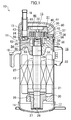
- the compressor (10) includes a casing (11), a motor (20), and a compression mechanism (30).
- the casing (11) contains the motor (20) and the compression mechanism (30).
- the casing (11) is a closed container shaped in a form of an oblong cylinder.
- the casing (11) includes: a body (12) cylindrically shaped and having both axial ends opened; an upper end plate (13) closing an upper end portion of the body (12); and a lower end plate (14) closing a lower end portion of the body (12).
- An interior space of the casing (11) is vertically compartmentalized by a housing (50).
- a space above the housing (50) defines an upper space (15), and a space below the housing (50) defines a lower space (16).
- an oil storage (17) is formed on the bottom of the casing (11).
- the oil storage (17) stores lubricant for lubricating the compression mechanism (30) and the sliding parts of a bearing.
- a suction pipe (18) and a discharge pipe (19) are attached to the casing (11).
- the suction pipe (18) penetrates an upper portion of the upper end plate (13).
- An outflow end of the suction pipe (18) is connected to a suction pipe coupling (65) of the compression mechanism (30).
- the suction pipe (19) penetrates the body (12).
- An inflow end portion of the suction pipe (19) is opened to the lower space (16).
- the suction pipe (20) is housed in the lower space (16).
- the motor (20) includes a stator (21) and a rotor (22).
- the stator (21) is cylindrically shaped, and an outer periphery of the stator (21) is secured to the body (12) of the casing (11).
- the rotor (22) is cylindrically shaped, and inserted into the stator (21).
- Secured in the rotor (22) is a drive shaft (23) which penetrates this rotor (22).
- the drive shaft (23) connects the motor (20) and the compression mechanism (30).
- the drive shaft (23) includes a main shaft (24), and an eccentric portion (25) integrally formed above the main shaft (24).
- the eccentric portion (25) is smaller in diameter than the main shaft (24), and is offset at a predetermined eccentricity with respect to a shaft center of the main shaft (24).
- the main shaft (24) is rotatably supported by a lower bearing (28) and an upper bearing (53).
- a lower end portion of the drive shaft (23) is provided with an oil-feed pump (26).
- a suction port of the oil-feed pump (26) is opened to the oil storage (17).
- the lubricant pumped by the oil-feed pump (26) is supplied through an oil-feed passage (27) in the drive shaft (23) to the compression mechanism (30) and sliding parts of the bearings (28, 53).
- the housing (50) is secured to the upper end portion of the body (12) of the casing (11).
- the housing (50) is shaped generally cylindrically, and has the main shaft (24) penetrate an interior of the housing (50).
- the housing (50) includes a small diameter part (51) formed around the upper bearing (53), and a large diameter part (52) formed around the eccentric portion (25).
- An outer periphery of the large diameter part (52) is secured to the casing (11).
- Defined in the large diameter part (52) is a high-pressure back-pressure chamber (54) shaped generally cylindrically. This high-pressure back-pressure chamber (54) is supplied with high-pressure lubricant flowing from the oil-feed passage (27).
- the high-pressure back-pressure chamber (54) is the same in ambient pressure as a refrigerant discharged from the compression mechanism (30). Furthermore, the large diameter part (52) of the housing (50) is provided with a seal ring (55) annularly shaped and placed on a top end of an inner peripheral portion of the large diameter part (52). The seal ring (55) provides an airtight separation between the high-pressure back-pressure chamber (54) and a middle-pressure back-pressure chamber (56).
- the high-pressure back-pressure chamber (54) is defined in the inner periphery of the seal ring (55), and the middle-pressure back-pressure chamber (56) is located to the outer periphery of the seal ring (55).
- the compression mechanism (30) is placed above the housing (50).
- the compression mechanism (30) is a scroll-type rotating compression mechanism including a fixed scroll (40) and an orbiting scroll (35).
- the fixed scroll (40) and the orbiting scroll (35) has a compression chamber (31) defined therebetween.
- the fixed scroll (40) is bolted on the housing (50), and the orbiting scroll (35) is rotatably housed between the fixed scroll (40) and the housing (50).
- the fixed scroll (40) includes a fixed end plate part (41) shaped into a generally circular disk, a fixed wrap (42) supported by a lower surface of the fixed end plate part (41), and a rim (43) formed radially outside the fixed wrap (42).
- a discharge port (32) is formed on a center of the fixed end plate part (41).
- the discharge port (32) vertically penetrates the fixed end plate part (41).
- a discharge chamber (46) is located above the discharge port (32).
- the discharge chamber (46) is in communication with the lower space (16) through a not-shown discharge flow passage.
- the lower space (16) is the same in ambient pressure as a refrigerant discharged from the compression mechanism (30).
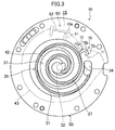
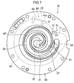
- the fixed wrap (42) is formed by spirally extending from the discharge port (32) toward the rip portion (43) (see FIG. 3 ).
- a suction port (34) is formed on the rim (43) of the fixed scroll (40).
- the suction pipe (34) connects to an outflow portion of the suction pipe (18).
- the orbiting scroll (35) includes a movable end plate part (36) shaped into a generally circular disk, a movable wrap (37) supported by an upper surface of the movable end plate part (36), and a boss (38) supported by the lower surface of the movable end plate part (36).
- the movable end plate part (36) is supported by the housing (50) through an Oldham's coupling (58).
- the movable wrap (37) is formed by spirally extending near a center of the movable end plate part (36) toward the rim (43) of the fixed scroll (40).
- the boss (38) is shaped into a cylinder of which bottom is open, and has the eccentric portion (25) inserted thereinto.
- a generally annular recess is defined on a top end face of the large diameter part (52) of the housing (50).
- the middle-pressure back-pressure chamber (56) is defined in this recess.
- This middle-pressure back-pressure chamber (56) is supplied with the refrigerant, of the compression chamber (31), under intermediate pressure.
- the middle-pressure back-pressure chamber (56) is in communication with the upper space (15) through a not-shown communication passage.
- the middle-pressure back-pressure chamber (56) is substantially the same in ambient pressure as the upper space (15).
- the compression mechanism (30) is provided with an introduction mechanism (70) and an auxiliary introduction mechanism (80) both of which supply the refrigerant of the compression chamber (31) to the middle-pressure back-pressure chamber (56).
- the introduction mechanism (70) and the auxiliary introduction mechanism (80) will be described in detail with reference to FIGS. 2 and 3 .
- the introduction mechanism (70) includes a movable vertical hole (71) and a fixed communication groove (72).
- the movable vertical hole (71) is a through hole axially penetrating the movable end plate part (36) of the orbiting scroll (35).
- the movable vertical hole (71) is defined in a form of an elongated cylinder.
- the orbiting scroll (35) rotates, the movable vertical hole (71) is displaced in a turning radius substantially equal to that of the orbiting scroll (35).
- An orbit of the movable vertical hole (71) axially overlaps with the middle-pressure back-pressure chamber (56). In other words, the movable vertical hole (71) is always in communication with the middle-pressure back-pressure chamber (56) no matter where the movable vertical hole (71) is positioned during the rotation.
- the fixed communication groove (72) is defined on the lower surface (i.e., a thrust surface) of the rim (43) of the fixed scroll (40). An inflow end of the fixed communication groove (72) is opened to an inner peripheral surface of the rim (43).
- the fixed communication groove (72) has an outflow end defined at a position at which the communication between the outflow end and the movable vertical hole (71) is opened and closed. More specifically, the fixed communication groove (72) includes an inflow groove portion (72a), an intermediate groove portion (72b), and an outflow groove portion (72c) continuously and integrally formed with one another.
- the inflow groove portion (72a) extends radially outwardly from the inner peripheral surface of the rim (43).
- the intermediate groove portion (72b) bends at radially outward end portion of the inflow groove portion (72a) and circumferentially extends.
- the outflow groove portion (72c) bends radially inwardly at an outflow of the intermediate groove portion (72b), and the outflow end of the outflow groove portion (72c) overlaps with the orbit of the movable vertical hole (71).
- the fixed communication groove (72) and the movable vertical hole (71) intermittently communicate with each other, with the rotation of the orbiting scroll (35).
- the communication between the fixed communication groove (72) and the movable vertical hole (71) in the introduction mechanism (70) defines an introduction passage which provides communication between an outermost compression chamber (31) and the middle-pressure back-pressure chamber (56).
- the introduction mechanism (70) supplies, via the introduction passages (71, 72), the middle-pressure back-pressure chamber (56) with the refrigerant, in the compression chamber (31), under intermediate pressure in the middle of compression.
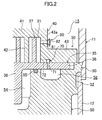
- the auxiliary introduction mechanism (80) includes a fixed communication hole (81) acting as an auxiliary introduction passage, and an opening and closing mechanism (a check valve (82)) to open and close the fixed communication hole (81).
- the fixed communication hole (81) is defined on a peripheral wall portion (43a). As illustrated in FIG. 2 , the peripheral wall portion (43a) is included in the rim (43) of the fixed scroll (40), and formed near the fixed end plate part (41). The fixed communication hole (81) radially penetrates the peripheral wall portion (43a), and provides communication between the outermost compression chamber (31) and the upper space (15). On an interior wall surface of the rim (43) of the fixed scroll (40), the inflow end of the fixed communication hole (81) is located closer to the suction port (34) than that of the fixed communication groove (72) is. Specifically, the fixed communication hole (81) defines an introduction passage closer to the low-pressure side (the suction side) than the fixed communication groove (72) is.
- the check valve (82) is provided to the outflow portion of the fixed communication hole (81). While allowing the refrigerant to flow from the compression chamber (31) to the upper space (15), the check valve (82) blocks the refrigerant from flowing from the upper space (15) to the compression chamber (31). Moreover, the check valve (82) is a reed valve to be opened, depending on a differential pressure between the compression chamber (31) and the upper space (15).
- the middle-pressure back-pressure chamber (56) and, eventually, the upper space (15) experience a pressure drop.
- the check valve (82) is opened.
- the refrigerant of the compression chamber (31) is introduced through the fixed communication hole (81) and the upper space (15) into the middle-pressure back-pressure chamber (56).
- the auxiliary introduction mechanism (80) supplies the refrigerant of the compression chamber (31) to the middle-pressure back-pressure chamber (56) (details will be described later).
- the orbiting scroll (35) rotates, the refrigerant is gradually sucked from the suction port (34) to an outermost fluid chamber. After that, this fluid chamber is completely closed so that the compression chamber (31) is defined (see FIG. 3 ). Furthermore, when the drive shaft (23) rotates, the volume of the outermost compression chamber (31) decreases, and the compression chamber (31) gradually moves closer to the discharge port (32).
- the movable vertical hole (71) and fixed communication groove (72) communicate with each other.
- This communication allows the refrigerant, of the compression chamber (31), in the middle of compression to pass through the fixed communication hole (72) and the upper space (71) in the stated order, and to be introduced into the middle-pressure back-pressure chamber (56).
- an opening area of the movable vertical hole (71) with respect to the fixed communication groove (72) increases to a maximum in the introduction mechanism (70) (see FIG. 6 ).
- the middle-pressure back-pressure chamber (56) is maintained under a target pressure (hereinafter referred to as a target back pressure).
- Such a normal driving operation of the compressor (10) does not involve the activation of the auxiliary introduction mechanism (80). This is because the check valve (82) of the fixed communication hole (81) is left closed when the middle-pressure back-pressure chamber (56) is maintained under the target pressure as described above. Accordingly, in such a normal operation, the refrigerant of the compression chamber (31) is not supplied through the auxiliary introduction passage (the fixed communication hole (81)) to the upper space (15).
- the tilt of the orbiting scroll (35) can create a relatively wide gap of the thrust surface between the movable end plate part (36) of the orbiting scroll (35) and the rim (43) of the fixed scroll (40). Then, the refrigerant, of the middle-pressure back-pressure chamber (56), under the intermediate pressure can leak through this gap into the suction side (the low-pressure side) of the compression chamber (31). As a result, as illustrated in FIG. 4 , a pressure Pu of the middle-pressure back-pressure chamber (56) falls significantly below an original target pressure Po, so that desired pressing force could not be applied to the orbiting scroll (35).
- the tilt of the orbiting scroll (35) can create a relatively wide gap between a tip of the fixed wrap (42) and the movable end plate part (36), and between a tip of the movable wrap (37) and the fixed end plate part (41).
- the refrigerant under a relatively high pressure toward the discharge port (32) can leak through this gap into the compression chamber (31) toward the suction port.
- This refrigerant can be compressed again to have an excessive pressure.
- the internal pressure of the compression chamber rises higher in total than that in the normal operation. Such a pressure rise can increase the load of gas, and cause the increased load to create greater force to separate the orbiting scroll (35) from the fixed scroll (40).
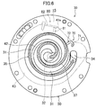
- the fixed communication hole (81) is defined and positioned to be left open to the outermost fluid chamber throughout the second period illustrated in FIG. 4 .
- an inflow port of the fixed communication hole (81) is provided to open to a fluid chamber in the compression mechanism (30) when the angle of rotation of the orbiting scroll (35) ranges from ⁇ 1 to ⁇ 3.
- the angle of rotation ⁇ 1 is slightly smaller than an angle of rotation corresponding to a time point when a compression phase of the outermost compression chamber (31) starts.
- the angle of rotation ⁇ 3 is subsequent to a time point (the angle of rotation ⁇ 2) when the introduction mechanism (70) starts the communication between the compression chamber (31) and the middle-pressure back-pressure chamber (56).
- the angle of rotation ⁇ 3 is slightly prior to a time point (the angle of rotation ⁇ 4) when the opening area of the movable vertical hole (71) with respect to the fixed communication groove (72) increases to the maximum.
- the auxiliary introduction mechanism (80) then introduces the refrigerant of the compression chamber (31) into the middle-pressure back-pressure chamber (56).
- the internal pressure of the compression chamber (31) is rising; whereas, the internal pressure of the middle-pressure back-pressure chamber (56) is having a difficult time rising.
- the pressure of the compression chamber (31) rises by a predetermined pressure than the pressure of the upper space (15), and the check valve (82) is opened.
- the refrigerant, of the compression chamber (31), in the middle of compression is supplied through the fixed communication hole (81) and the upper space (15) to the middle-pressure back-pressure chamber (56).
- the pressure of the middle-pressure back-pressure chamber (56) quickly rises.
- the introduction mechanism (70) supplies the refrigerant, of the compression chamber (31), in the middle of compression to the middle-pressure back-pressure chamber (56).
- the refrigerant of the compression chamber (31) is supplied to the middle-pressure back-pressure chamber (56) throughout the second period as well as the first period.
- FIG. 4 shows that a part of the second period overlaps with a part of the first period, and the second period ends at a time point almost immediately before the angle of rotation ⁇ 4.
- the auxiliary introduction mechanism (80) supplies the fluid of the compression chamber (31) to the middle-pressure back-pressure chamber (56) before the introduction mechanism (70) does.
- Such a feature contributes to a quick rise in the pressure of the middle-pressure back-pressure chamber (56).
- the tilt of the orbiting scroll (35) may be removed quickly, and the compressor (10) may return to the normal operation.
- a part of the second period overlaps with a part of the first period.
- the introduction mechanism (70) supplies the fluid to the middle-pressure back-pressure chamber (56)
- the auxiliary introduction mechanism (80) supplies the fluid to the middle-pressure back-pressure chamber (56).
- the inflow end of the auxiliary introduction passage (81) of the auxiliary introduction mechanism (80) is located slightly closer to the low-pressure side (the suction side) than the inflow end of the introduction passages (71, 72) of the introduction mechanism (70) is.
- such a feature may reliably reduce a risk that the pressure of the middle-pressure back-pressure chamber (56) exceeds the target pressure obtained by the introduction mechanism (70).
- a part of the second period overlaps with a part of the first period.
- the auxiliary introduction mechanism (80) supplies the refrigerant to the middle-pressure back-pressure chamber (56)
- the introduction mechanism (70) supplies the refrigerant to the middle-pressure back-pressure chamber (56).
- both of the periods do not necessarily have to overlap with each other.
- the first period may be set after the end of the second period.
- the auxiliary introduction passage (81) is defined on the peripheral wall portion (43a) of the rim (43) of the fixed scroll (40).
- a through hole may be formed on the fixed end plate part (41) of the fixed scroll (40) to act as the auxiliary introduction passage (81).
- the check valve (82) is attached to an upper portion of the fixed end plate part (41) to open and close the upper end portion of the auxiliary introduction passage (81).
- the present invention is useful for a scroll compressor and, in particular, as a counter measure to a tilt of an orbiting scroll.
Landscapes
- Engineering & Computer Science (AREA)
- Mechanical Engineering (AREA)
- General Engineering & Computer Science (AREA)
- Rotary Pumps (AREA)
- Applications Or Details Of Rotary Compressors (AREA)
Applications Claiming Priority (2)
| Application Number | Priority Date | Filing Date | Title |
|---|---|---|---|
| JP2013249363A JP5812083B2 (ja) | 2013-12-02 | 2013-12-02 | スクロール型圧縮機 |
| PCT/JP2014/006007 WO2015083369A1 (fr) | 2013-12-02 | 2014-12-02 | Compresseur à volutes |
Publications (3)
| Publication Number | Publication Date |
|---|---|
| EP3073117A1 true EP3073117A1 (fr) | 2016-09-28 |
| EP3073117A4 EP3073117A4 (fr) | 2017-09-20 |
| EP3073117B1 EP3073117B1 (fr) | 2021-01-20 |
Family
ID=53273153
Family Applications (1)
| Application Number | Title | Priority Date | Filing Date |
|---|---|---|---|
| EP14867598.6A Active EP3073117B1 (fr) | 2013-12-02 | 2014-12-02 | Compresseur à volutes |
Country Status (5)
| Country | Link |
|---|---|
| US (1) | US10100833B2 (fr) |
| EP (1) | EP3073117B1 (fr) |
| JP (1) | JP5812083B2 (fr) |
| CN (1) | CN105765226B (fr) |
| WO (1) | WO2015083369A1 (fr) |
Families Citing this family (6)
| Publication number | Priority date | Publication date | Assignee | Title |
|---|---|---|---|---|
| SG10201906756RA (en) | 2015-02-17 | 2019-08-27 | Evoqua Water Tech Llc | Reduced volume electrochlorination cells and methods of manufacturing same |
| JP6737308B2 (ja) | 2018-07-05 | 2020-08-05 | ダイキン工業株式会社 | スクロール圧縮機 |
| TWI702492B (zh) * | 2019-11-15 | 2020-08-21 | 致伸科技股份有限公司 | 滾輪滑鼠 |
| JP6987295B1 (ja) * | 2021-09-03 | 2021-12-22 | 日立ジョンソンコントロールズ空調株式会社 | スクロール圧縮機及び冷凍サイクル装置 |
| JP7481640B2 (ja) | 2022-08-01 | 2024-05-13 | ダイキン工業株式会社 | スクロール圧縮機及び冷凍装置 |
| CN116877428B (zh) * | 2023-08-25 | 2026-01-30 | 珠海凌达压缩机有限公司 | 压缩机 |
Family Cites Families (11)
| Publication number | Priority date | Publication date | Assignee | Title |
|---|---|---|---|---|
| JPS6153486A (ja) * | 1984-08-22 | 1986-03-17 | Hitachi Ltd | スクロ−ル圧縮機 |
| JPS6444385U (fr) * | 1987-09-11 | 1989-03-16 | ||
| JP2557533B2 (ja) * | 1989-10-18 | 1996-11-27 | 株式会社日立製作所 | 密閉型可変速スクロール圧縮機 |
| JPH051677A (ja) * | 1991-06-27 | 1993-01-08 | Hitachi Ltd | スクロール圧縮機 |
| JP2002021753A (ja) * | 2000-07-11 | 2002-01-23 | Fujitsu General Ltd | スクロール圧縮機 |
| JP2006183499A (ja) * | 2004-12-27 | 2006-07-13 | Hitachi Ltd | 容積形圧縮機 |
| CN102016319B (zh) * | 2008-04-22 | 2013-11-06 | 松下电器产业株式会社 | 涡旋压缩机 |
| US8979516B2 (en) | 2008-07-15 | 2015-03-17 | Daikin Industries, Ltd. | Back pressure space of a scroll compressor |
| JP4614009B1 (ja) | 2009-09-02 | 2011-01-19 | ダイキン工業株式会社 | スクロール圧縮機 |
| JP5599226B2 (ja) | 2010-05-17 | 2014-10-01 | 三菱製鋼株式会社 | 開閉装置 |
| CN103189651B (zh) | 2010-11-08 | 2014-07-30 | 大金工业株式会社 | 涡旋压缩机 |
-
2013
- 2013-12-02 JP JP2013249363A patent/JP5812083B2/ja active Active
-
2014
- 2014-12-02 EP EP14867598.6A patent/EP3073117B1/fr active Active
- 2014-12-02 WO PCT/JP2014/006007 patent/WO2015083369A1/fr not_active Ceased
- 2014-12-02 CN CN201480064363.XA patent/CN105765226B/zh active Active
- 2014-12-02 US US15/100,911 patent/US10100833B2/en active Active
Also Published As
| Publication number | Publication date |
|---|---|
| JP5812083B2 (ja) | 2015-11-11 |
| JP2015105642A (ja) | 2015-06-08 |
| US10100833B2 (en) | 2018-10-16 |
| CN105765226B (zh) | 2017-07-07 |
| WO2015083369A1 (fr) | 2015-06-11 |
| EP3073117A4 (fr) | 2017-09-20 |
| US20160298626A1 (en) | 2016-10-13 |
| CN105765226A (zh) | 2016-07-13 |
| EP3073117B1 (fr) | 2021-01-20 |
Similar Documents
| Publication | Publication Date | Title |
|---|---|---|
| EP3073117B1 (fr) | Compresseur à volutes | |
| KR101529415B1 (ko) | 스크롤형 압축기 | |
| US9638191B2 (en) | Capacity modulated scroll compressor | |
| KR101076564B1 (ko) | 스크롤 압축기 | |
| US9903370B2 (en) | Scroll compressor with reduced upsetting moment | |
| EP2863059B1 (fr) | Dispositif de compression à volute | |
| EP2639457B1 (fr) | Compresseur à volute | |
| US10138887B2 (en) | Scroll compressor | |
| EP2369182A1 (fr) | Compresseur à volutes | |
| CN106062369B (zh) | 涡旋式压缩机 | |
| WO2016136185A1 (fr) | Compresseur de type à spirale | |
| EP2913531A1 (fr) | Compresseur à spirales avec masse d'équilibrage | |
| EP3575605B1 (fr) | Compresseur hermétique | |
| EP2947320B1 (fr) | Compresseur à spirale | |
| CN112204259B (zh) | 涡旋式压缩机 | |
| EP4102074B1 (fr) | Compresseur à spirale | |
| CN119585527A (zh) | 涡旋压缩机及制冷装置 | |
| JP4879078B2 (ja) | 圧縮機 | |
| EP3726058A1 (fr) | Compresseur motorisé | |
| JP2013245557A (ja) | 電動圧縮機 |
Legal Events
| Date | Code | Title | Description |
|---|---|---|---|
| PUAI | Public reference made under article 153(3) epc to a published international application that has entered the european phase |
Free format text: ORIGINAL CODE: 0009012 |
|
| 17P | Request for examination filed |
Effective date: 20160523 |
|
| AK | Designated contracting states |
Kind code of ref document: A1 Designated state(s): AL AT BE BG CH CY CZ DE DK EE ES FI FR GB GR HR HU IE IS IT LI LT LU LV MC MK MT NL NO PL PT RO RS SE SI SK SM TR |
|
| AX | Request for extension of the european patent |
Extension state: BA ME |
|
| DAX | Request for extension of the european patent (deleted) | ||
| A4 | Supplementary search report drawn up and despatched |
Effective date: 20170823 |
|
| RIC1 | Information provided on ipc code assigned before grant |
Ipc: F04C 27/00 20060101ALI20170817BHEP Ipc: F04C 18/02 20060101AFI20170817BHEP |
|
| STAA | Information on the status of an ep patent application or granted ep patent |
Free format text: STATUS: EXAMINATION IS IN PROGRESS |
|
| 17Q | First examination report despatched |
Effective date: 20200212 |
|
| GRAP | Despatch of communication of intention to grant a patent |
Free format text: ORIGINAL CODE: EPIDOSNIGR1 |
|
| STAA | Information on the status of an ep patent application or granted ep patent |
Free format text: STATUS: GRANT OF PATENT IS INTENDED |
|
| INTG | Intention to grant announced |
Effective date: 20200923 |
|
| GRAS | Grant fee paid |
Free format text: ORIGINAL CODE: EPIDOSNIGR3 |
|
| GRAA | (expected) grant |
Free format text: ORIGINAL CODE: 0009210 |
|
| STAA | Information on the status of an ep patent application or granted ep patent |
Free format text: STATUS: THE PATENT HAS BEEN GRANTED |
|
| AK | Designated contracting states |
Kind code of ref document: B1 Designated state(s): AL AT BE BG CH CY CZ DE DK EE ES FI FR GB GR HR HU IE IS IT LI LT LU LV MC MK MT NL NO PL PT RO RS SE SI SK SM TR |
|
| REG | Reference to a national code |
Ref country code: GB Ref legal event code: FG4D |
|
| REG | Reference to a national code |
Ref country code: CH Ref legal event code: EP |
|
| REG | Reference to a national code |
Ref country code: DE Ref legal event code: R096 Ref document number: 602014074461 Country of ref document: DE |
|
| REG | Reference to a national code |
Ref country code: AT Ref legal event code: REF Ref document number: 1356622 Country of ref document: AT Kind code of ref document: T Effective date: 20210215 |
|
| REG | Reference to a national code |
Ref country code: IE Ref legal event code: FG4D |
|
| REG | Reference to a national code |
Ref country code: NL Ref legal event code: MP Effective date: 20210120 |
|
| REG | Reference to a national code |
Ref country code: LT Ref legal event code: MG9D |
|
| REG | Reference to a national code |
Ref country code: AT Ref legal event code: MK05 Ref document number: 1356622 Country of ref document: AT Kind code of ref document: T Effective date: 20210120 |
|
| PG25 | Lapsed in a contracting state [announced via postgrant information from national office to epo] |
Ref country code: LT Free format text: LAPSE BECAUSE OF FAILURE TO SUBMIT A TRANSLATION OF THE DESCRIPTION OR TO PAY THE FEE WITHIN THE PRESCRIBED TIME-LIMIT Effective date: 20210120 Ref country code: PT Free format text: LAPSE BECAUSE OF FAILURE TO SUBMIT A TRANSLATION OF THE DESCRIPTION OR TO PAY THE FEE WITHIN THE PRESCRIBED TIME-LIMIT Effective date: 20210520 Ref country code: FI Free format text: LAPSE BECAUSE OF FAILURE TO SUBMIT A TRANSLATION OF THE DESCRIPTION OR TO PAY THE FEE WITHIN THE PRESCRIBED TIME-LIMIT Effective date: 20210120 Ref country code: HR Free format text: LAPSE BECAUSE OF FAILURE TO SUBMIT A TRANSLATION OF THE DESCRIPTION OR TO PAY THE FEE WITHIN THE PRESCRIBED TIME-LIMIT Effective date: 20210120 Ref country code: GR Free format text: LAPSE BECAUSE OF FAILURE TO SUBMIT A TRANSLATION OF THE DESCRIPTION OR TO PAY THE FEE WITHIN THE PRESCRIBED TIME-LIMIT Effective date: 20210421 Ref country code: BG Free format text: LAPSE BECAUSE OF FAILURE TO SUBMIT A TRANSLATION OF THE DESCRIPTION OR TO PAY THE FEE WITHIN THE PRESCRIBED TIME-LIMIT Effective date: 20210420 Ref country code: NL Free format text: LAPSE BECAUSE OF FAILURE TO SUBMIT A TRANSLATION OF THE DESCRIPTION OR TO PAY THE FEE WITHIN THE PRESCRIBED TIME-LIMIT Effective date: 20210120 Ref country code: NO Free format text: LAPSE BECAUSE OF FAILURE TO SUBMIT A TRANSLATION OF THE DESCRIPTION OR TO PAY THE FEE WITHIN THE PRESCRIBED TIME-LIMIT Effective date: 20210420 |
|
| PG25 | Lapsed in a contracting state [announced via postgrant information from national office to epo] |
Ref country code: SE Free format text: LAPSE BECAUSE OF FAILURE TO SUBMIT A TRANSLATION OF THE DESCRIPTION OR TO PAY THE FEE WITHIN THE PRESCRIBED TIME-LIMIT Effective date: 20210120 Ref country code: AT Free format text: LAPSE BECAUSE OF FAILURE TO SUBMIT A TRANSLATION OF THE DESCRIPTION OR TO PAY THE FEE WITHIN THE PRESCRIBED TIME-LIMIT Effective date: 20210120 Ref country code: LV Free format text: LAPSE BECAUSE OF FAILURE TO SUBMIT A TRANSLATION OF THE DESCRIPTION OR TO PAY THE FEE WITHIN THE PRESCRIBED TIME-LIMIT Effective date: 20210120 Ref country code: RS Free format text: LAPSE BECAUSE OF FAILURE TO SUBMIT A TRANSLATION OF THE DESCRIPTION OR TO PAY THE FEE WITHIN THE PRESCRIBED TIME-LIMIT Effective date: 20210120 Ref country code: PL Free format text: LAPSE BECAUSE OF FAILURE TO SUBMIT A TRANSLATION OF THE DESCRIPTION OR TO PAY THE FEE WITHIN THE PRESCRIBED TIME-LIMIT Effective date: 20210120 |
|
| PG25 | Lapsed in a contracting state [announced via postgrant information from national office to epo] |
Ref country code: IS Free format text: LAPSE BECAUSE OF FAILURE TO SUBMIT A TRANSLATION OF THE DESCRIPTION OR TO PAY THE FEE WITHIN THE PRESCRIBED TIME-LIMIT Effective date: 20210520 |
|
| REG | Reference to a national code |
Ref country code: DE Ref legal event code: R097 Ref document number: 602014074461 Country of ref document: DE |
|
| PG25 | Lapsed in a contracting state [announced via postgrant information from national office to epo] |
Ref country code: SM Free format text: LAPSE BECAUSE OF FAILURE TO SUBMIT A TRANSLATION OF THE DESCRIPTION OR TO PAY THE FEE WITHIN THE PRESCRIBED TIME-LIMIT Effective date: 20210120 Ref country code: CZ Free format text: LAPSE BECAUSE OF FAILURE TO SUBMIT A TRANSLATION OF THE DESCRIPTION OR TO PAY THE FEE WITHIN THE PRESCRIBED TIME-LIMIT Effective date: 20210120 Ref country code: EE Free format text: LAPSE BECAUSE OF FAILURE TO SUBMIT A TRANSLATION OF THE DESCRIPTION OR TO PAY THE FEE WITHIN THE PRESCRIBED TIME-LIMIT Effective date: 20210120 |
|
| PLBE | No opposition filed within time limit |
Free format text: ORIGINAL CODE: 0009261 |
|
| STAA | Information on the status of an ep patent application or granted ep patent |
Free format text: STATUS: NO OPPOSITION FILED WITHIN TIME LIMIT |
|
| PG25 | Lapsed in a contracting state [announced via postgrant information from national office to epo] |
Ref country code: DK Free format text: LAPSE BECAUSE OF FAILURE TO SUBMIT A TRANSLATION OF THE DESCRIPTION OR TO PAY THE FEE WITHIN THE PRESCRIBED TIME-LIMIT Effective date: 20210120 Ref country code: ES Free format text: LAPSE BECAUSE OF FAILURE TO SUBMIT A TRANSLATION OF THE DESCRIPTION OR TO PAY THE FEE WITHIN THE PRESCRIBED TIME-LIMIT Effective date: 20210120 Ref country code: SK Free format text: LAPSE BECAUSE OF FAILURE TO SUBMIT A TRANSLATION OF THE DESCRIPTION OR TO PAY THE FEE WITHIN THE PRESCRIBED TIME-LIMIT Effective date: 20210120 Ref country code: RO Free format text: LAPSE BECAUSE OF FAILURE TO SUBMIT A TRANSLATION OF THE DESCRIPTION OR TO PAY THE FEE WITHIN THE PRESCRIBED TIME-LIMIT Effective date: 20210120 |
|
| 26N | No opposition filed |
Effective date: 20211021 |
|
| PG25 | Lapsed in a contracting state [announced via postgrant information from national office to epo] |
Ref country code: AL Free format text: LAPSE BECAUSE OF FAILURE TO SUBMIT A TRANSLATION OF THE DESCRIPTION OR TO PAY THE FEE WITHIN THE PRESCRIBED TIME-LIMIT Effective date: 20210120 |
|
| PG25 | Lapsed in a contracting state [announced via postgrant information from national office to epo] |
Ref country code: SI Free format text: LAPSE BECAUSE OF FAILURE TO SUBMIT A TRANSLATION OF THE DESCRIPTION OR TO PAY THE FEE WITHIN THE PRESCRIBED TIME-LIMIT Effective date: 20210120 |
|
| PG25 | Lapsed in a contracting state [announced via postgrant information from national office to epo] |
Ref country code: IS Free format text: LAPSE BECAUSE OF FAILURE TO SUBMIT A TRANSLATION OF THE DESCRIPTION OR TO PAY THE FEE WITHIN THE PRESCRIBED TIME-LIMIT Effective date: 20210520 |
|
| PG25 | Lapsed in a contracting state [announced via postgrant information from national office to epo] |
Ref country code: MC Free format text: LAPSE BECAUSE OF FAILURE TO SUBMIT A TRANSLATION OF THE DESCRIPTION OR TO PAY THE FEE WITHIN THE PRESCRIBED TIME-LIMIT Effective date: 20210120 |
|
| REG | Reference to a national code |
Ref country code: CH Ref legal event code: PL |
|
| GBPC | Gb: european patent ceased through non-payment of renewal fee |
Effective date: 20211202 |
|
| REG | Reference to a national code |
Ref country code: BE Ref legal event code: MM Effective date: 20211231 |
|
| PG25 | Lapsed in a contracting state [announced via postgrant information from national office to epo] |
Ref country code: LU Free format text: LAPSE BECAUSE OF NON-PAYMENT OF DUE FEES Effective date: 20211202 Ref country code: IE Free format text: LAPSE BECAUSE OF NON-PAYMENT OF DUE FEES Effective date: 20211202 Ref country code: GB Free format text: LAPSE BECAUSE OF NON-PAYMENT OF DUE FEES Effective date: 20211202 |
|
| PG25 | Lapsed in a contracting state [announced via postgrant information from national office to epo] |
Ref country code: BE Free format text: LAPSE BECAUSE OF NON-PAYMENT OF DUE FEES Effective date: 20211231 |
|
| PG25 | Lapsed in a contracting state [announced via postgrant information from national office to epo] |
Ref country code: LI Free format text: LAPSE BECAUSE OF NON-PAYMENT OF DUE FEES Effective date: 20211231 Ref country code: CH Free format text: LAPSE BECAUSE OF NON-PAYMENT OF DUE FEES Effective date: 20211231 |
|
| PG25 | Lapsed in a contracting state [announced via postgrant information from national office to epo] |
Ref country code: HU Free format text: LAPSE BECAUSE OF FAILURE TO SUBMIT A TRANSLATION OF THE DESCRIPTION OR TO PAY THE FEE WITHIN THE PRESCRIBED TIME-LIMIT; INVALID AB INITIO Effective date: 20141202 |
|
| PG25 | Lapsed in a contracting state [announced via postgrant information from national office to epo] |
Ref country code: CY Free format text: LAPSE BECAUSE OF FAILURE TO SUBMIT A TRANSLATION OF THE DESCRIPTION OR TO PAY THE FEE WITHIN THE PRESCRIBED TIME-LIMIT Effective date: 20210120 |
|
| P01 | Opt-out of the competence of the unified patent court (upc) registered |
Effective date: 20230525 |
|
| PG25 | Lapsed in a contracting state [announced via postgrant information from national office to epo] |
Ref country code: MK Free format text: LAPSE BECAUSE OF FAILURE TO SUBMIT A TRANSLATION OF THE DESCRIPTION OR TO PAY THE FEE WITHIN THE PRESCRIBED TIME-LIMIT Effective date: 20210120 |
|
| PG25 | Lapsed in a contracting state [announced via postgrant information from national office to epo] |
Ref country code: MT Free format text: LAPSE BECAUSE OF FAILURE TO SUBMIT A TRANSLATION OF THE DESCRIPTION OR TO PAY THE FEE WITHIN THE PRESCRIBED TIME-LIMIT Effective date: 20210120 |
|
| PG25 | Lapsed in a contracting state [announced via postgrant information from national office to epo] |
Ref country code: TR Free format text: LAPSE BECAUSE OF FAILURE TO SUBMIT A TRANSLATION OF THE DESCRIPTION OR TO PAY THE FEE WITHIN THE PRESCRIBED TIME-LIMIT Effective date: 20210120 |
|
| PGFP | Annual fee paid to national office [announced via postgrant information from national office to epo] |
Ref country code: DE Payment date: 20251028 Year of fee payment: 12 |
|
| PGFP | Annual fee paid to national office [announced via postgrant information from national office to epo] |
Ref country code: IT Payment date: 20251121 Year of fee payment: 12 |
|
| PGFP | Annual fee paid to national office [announced via postgrant information from national office to epo] |
Ref country code: FR Payment date: 20251117 Year of fee payment: 12 |